EP2833032A1 - EGR seal with a sieve insert and manufacturing method - Google Patents
EGR seal with a sieve insert and manufacturing method Download PDFInfo
- Publication number
- EP2833032A1 EP2833032A1 EP13178968.7A EP13178968A EP2833032A1 EP 2833032 A1 EP2833032 A1 EP 2833032A1 EP 13178968 A EP13178968 A EP 13178968A EP 2833032 A1 EP2833032 A1 EP 2833032A1
- Authority
- EP
- European Patent Office
- Prior art keywords
- seal
- sieve
- sieve element
- collar
- edge
- Prior art date
- Legal status (The legal status is an assumption and is not a legal conclusion. Google has not performed a legal analysis and makes no representation as to the accuracy of the status listed.)
- Withdrawn
Links
Images


Classifications
-
- F—MECHANICAL ENGINEERING; LIGHTING; HEATING; WEAPONS; BLASTING
- F16—ENGINEERING ELEMENTS AND UNITS; GENERAL MEASURES FOR PRODUCING AND MAINTAINING EFFECTIVE FUNCTIONING OF MACHINES OR INSTALLATIONS; THERMAL INSULATION IN GENERAL
- F16J—PISTONS; CYLINDERS; SEALINGS
- F16J15/00—Sealings
- F16J15/02—Sealings between relatively-stationary surfaces
- F16J15/06—Sealings between relatively-stationary surfaces with solid packing compressed between sealing surfaces
- F16J15/08—Sealings between relatively-stationary surfaces with solid packing compressed between sealing surfaces with exclusively metal packing
- F16J15/0818—Flat gaskets
-
- F—MECHANICAL ENGINEERING; LIGHTING; HEATING; WEAPONS; BLASTING
- F01—MACHINES OR ENGINES IN GENERAL; ENGINE PLANTS IN GENERAL; STEAM ENGINES
- F01N—GAS-FLOW SILENCERS OR EXHAUST APPARATUS FOR MACHINES OR ENGINES IN GENERAL; GAS-FLOW SILENCERS OR EXHAUST APPARATUS FOR INTERNAL-COMBUSTION ENGINES
- F01N13/00—Exhaust or silencing apparatus characterised by constructional features
- F01N13/18—Construction facilitating manufacture, assembly, or disassembly
- F01N13/1805—Fixing exhaust manifolds, exhaust pipes or pipe sections to each other, to engine or to vehicle body
- F01N13/1827—Sealings specially adapted for exhaust systems
-
- F—MECHANICAL ENGINEERING; LIGHTING; HEATING; WEAPONS; BLASTING
- F16—ENGINEERING ELEMENTS AND UNITS; GENERAL MEASURES FOR PRODUCING AND MAINTAINING EFFECTIVE FUNCTIONING OF MACHINES OR INSTALLATIONS; THERMAL INSULATION IN GENERAL
- F16J—PISTONS; CYLINDERS; SEALINGS
- F16J15/00—Sealings
- F16J15/02—Sealings between relatively-stationary surfaces
- F16J15/06—Sealings between relatively-stationary surfaces with solid packing compressed between sealing surfaces
- F16J15/064—Sealings between relatively-stationary surfaces with solid packing compressed between sealing surfaces the packing combining the sealing function with other functions
-
- F—MECHANICAL ENGINEERING; LIGHTING; HEATING; WEAPONS; BLASTING
- F16—ENGINEERING ELEMENTS AND UNITS; GENERAL MEASURES FOR PRODUCING AND MAINTAINING EFFECTIVE FUNCTIONING OF MACHINES OR INSTALLATIONS; THERMAL INSULATION IN GENERAL
- F16J—PISTONS; CYLINDERS; SEALINGS
- F16J15/00—Sealings
- F16J15/02—Sealings between relatively-stationary surfaces
- F16J15/06—Sealings between relatively-stationary surfaces with solid packing compressed between sealing surfaces
- F16J15/08—Sealings between relatively-stationary surfaces with solid packing compressed between sealing surfaces with exclusively metal packing
- F16J15/0818—Flat gaskets
- F16J2015/0856—Flat gaskets with a non-metallic coating or strip
Definitions
- the present invention relates to a seal with a sieve insert for an exhaust gas recirculation in the exhaust line of a motor vehicle that is driven by an internal combustion engine.
- the invention also relates to a production method for such an EGR seal with a sieve insert.
- Sieves that have been used up to now for this purpose in the exhaust gas recirculation are characterized by means of a significant pressure loss.
- the object of the present invention is to provide a remedy for this situation in the form of an improved sieve seal with reduced pressure loss and a corresponding production method.
- the sieve seal has a sieve part in the form of a sieve element with a three-dimensional design in the form of an approximately cup-shaped curvature, which is affixed in the region of the sealing function.
- the invention is thus based on the knowledge that the significant pressure loss of known sieve seals is largely caused by a comparatively low effective cross-sectional area.
- the integration of a sieve into a seal requires a cross-sectional leak-tightness relative to the outside and requires the assurance of the filter function in the region of the connection.
- the mechanical connection of the functional position and the sieve cloth ensures both functions.
- a three-dimensional design of the sieve increases the open cross-sectional area in comparison to known flat sieve elements and thus minimizes the pressure loss.
- the term "sieve cloth” is understood below to also mean knits or random layered structures such as fleeces, which all feature an outstanding heat resistance.
- a corresponding production method is based on the fact that an element composed of sieve cloth with an edge that is carded in a radially outward direction is deformed and inserted into a sealing element provided with a closed collar, with the edge of the element composed of mesh cloth encompasses the collar of the sealing element in such a way that at least a part of the edge embraces the collar from behind.
- a part of the edge and the collar are permanently connected to each other by folding or cramping so that a fluid can pass this arrangement only by traveling through the sieve element.
- a sieve element having said characteristics in operation is produced by deep drawing a region that is perforated by means of lasing, etching, or punching and is connected to the seal.
- the sieve element is connected to a seal by means of a bead that is closed in the form of a ring or the connection of the seal to the sieve element is embodied by means of a transition of the seal into the sieve element, with the sieve element embodied in the form of a perforated or micro-perforated deep drawn component.
- the cup-shaped sieve element can be conically or cylindrically shaped.
- the sieve element can be embodied as a cylindrical section that is closed at one free end, in particular by means of a circular piece of sieve cloth or by means of a compression and/or final closing of the sieve cloth by means of folding.
- the permanent connection between the part of the edge of the seal and the collar of the sieve element is produced by means of crimping and/or bending.
- the sieve element is produced by deep drawing a region that is perforated by means of lasing, etching, or punching and is connected to the seal. This region that has been perforated in the preparatory steps can thus be composed of the material of the seal, which has not been cut out or punched out in a region through which subsequent flow will pass and therefore remains integrally and tightly joined to the seal.
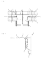
- Fig. 1 shows a detail of an exhaust gas recirculation, not shown in detail, in the exhaust line of a motor vehicle.
- a sieve seal 1 is provided in a plane D for the performance of a sealing function between a first flange 2 and a second flange 3.
- the sieve seal 1 has a sieve element 4, which is only indicated here, with a three-dimensional design that will be explained in greater detail below.
- the sieve element in the region of the sealing function is affixed to a seal 5 so that gases can travel via a full free cross-sectional area A of a pipe 6 adjoining the flange 3, through the sieve 4.
- a radial recess 8 is provided on the first flange 2. This recess 8 is dimensioned in order to accommodate the bead 7 so that when fixing the flanges 2, 3 by means of recesses 9, the seal 5 undergoes a full compression by means of them.
- Fig. 2 shows another embodiment of a sieve element 4 in a sectional side view.
- the sieve element 4 extends from the bead 7, tapering essentially in the shape of a truncated cone, into an end region 11, which in this instance is circular and is composed of the same sieve material as the casing of the truncated cone-shaped remaining part of the sieve element 4.
- the sieve seal 1 is a basically rotationally symmetrical component, which in the present embodiment, has external projections 10 of the seal 5 that deviate from this rotational symmetry.
- the seal 5 also has a circular, closed plate 12 extending concentrically around the bead 7.
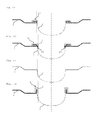
- a method for producing a connection between the sieve element 4 and the seal 5 will be depicted in conjunction with the sequence of Figs 3a - 3e by means of details of a sectional side view of another embodiment of a sieve seal 1.
- a crimped-over edge 14 that extends radially outward is preformed onto the sieve element 4 at a free end region 13.
- this edge 14 is being drawn so that it is further oriented inward.
- the sieve element 4 is then inserted into the associated seal 5; the seal 5, which was essentially flat before with a circumferential swage 15 has been provided with a closed collar 16.
- the closed collar 16 of the seal 5 and the crimped-over edge 14 of the sieve element 4 are matched to each other so that the crimped-over edge partially embraces the collar 16 from behind.
- the seal element is inserted so that the edge 14 of the element 4 composed of sieve cloth encompasses the collar 16 of the seal in such a way that at least part of the edge 14 embraces the collar 16 from behind and engages to a significant depth with the swage 15.
- Figs. 4a and 4b show details of a sectional side view to illustrate a production of a connection between the sieve element 4 and the seal 5 of another embodiment of a sieve seal 1 analogous to the sequence of Figs. 3a - 3e .
- the collar 16 adjoining the swage 15 of the seal 5 protrudes at approximately right angles, see Fig. 4a .
- the free end region 13 of the sieve element 4 comes to an end in a region extending approximately parallel to the collar 16 and ends at a crimped-over edge 14 extending radially outward, which embraces the collar 16 from above and behind. In a first step, this edge 14 is placed against the collar 16. This arrangement is then folded over by almost 90° and is placed flat into the swage 15, see Fig. 4b .
- An angle ⁇ indicates a slope of a flank at the transition from the seal 5 to the bead 7 that is formed in this way.
- FIGs. 5a through 5d shows views of another embodiment of a sieve seal 1.
- This sieve seal 1 is axially symmetrical having two projections 10 situated on opposite sides, see Fig. 5a .
- the projections 10 follow the seal 5 with a circularly enclosed plate 12 and the bead 7 as a connection between the seal 5 and the sieve element 4.
- the sieve element 4 tapers toward the end region 11 like a truncated cone, but in the end region 11, is compressed and closed in linear fashion, e.g. through folding, gluing, or welding.
- Figs. 6a - 6d show sectional side views of other embodiments of sieve seals 1. These embodiments differ with regard to the respective embodiment of the connecting region between the seal 5 and the sieve element 4; the exemplary embodiments described above essentially correspond to the sketch shown in Fig. 6a . For this reason, it is not addressed in further detail here.
- an important problem in sieve elements 4 composed of woven or braided fibers is to eliminate their lack of cross-sectional leak-tightness. In order to prevent leaks through the material of the sieve element 4 in the cross-sectional direction, the sieve element 4 together with a connection to the seal 5 must lie outside the region with the sealing function or must be enclosed by it in a sealed fashion.
- the embodiment shown in Fig. 6b includes a clamping ring 17 that becomes part within the connection of the sieve element 4 to the seal 5.
- the clamping ring 17 is connected to the collar 16 of the seal 5 by means of folding and on the other hand, it is affixed to the edge 14 of the sieve element 4 so that it is welded to part of the collar 16. Consequently, a welding edge 18 constitutes a transition from the sieve element 4 to a region of high cross-sectional leak-tightness so that a flow through the sieve seal 1 is only possible through the sieve element 4 on the other side of the welding edge 18.
- the embodiment according to Fig. 6d also includes the use of a clamping ring 17 with the design of the bead 7.
- Fig. 6c discloses a solution in which a closed collar 16 on the seal 5 is omitted.
- the sieve element 4 is produced by deep drawing a region that is connected to the seal 5 or it is made from the inner part of the seal 5 that usually is cut away. This region is perforated by means of lasing, etching, or punching especially in a separate step.
- the connection of the seal 5 to the end region 13 of the sieve element 4 is embodied by means of a transition of the seal 5 into the sieve element 4, with the sieve element 4 embodied in the form of a perforated or micro-perforated deep drawn component having a very high cross-sectional leak-tightness in comparison to every sieve cloth.
Landscapes
- Engineering & Computer Science (AREA)
- General Engineering & Computer Science (AREA)
- Mechanical Engineering (AREA)
- Chemical & Material Sciences (AREA)
- Combustion & Propulsion (AREA)
- Filtering Of Dispersed Particles In Gases (AREA)
Abstract
The present invention relates to a seal with a sieve insert for an exhaust gas recirculation (EGR) in the exhaust line of a motor vehicle that is driven by an internal combustion engine. The invention also relates to a production method for an EGR seal of this kind with a sieve insert.
In order to achieve an improved sieve seal with a reduced pressure loss and to produce it by means of a corresponding production method, the invention proposes that the sieve seal (1) have a sieve element (4) with a three-dimensional embodiment in the form of an approximately cup-shaped curvature, which is affixed in the region of the sealing function.
Description
- The present invention relates to a seal with a sieve insert for an exhaust gas recirculation in the exhaust line of a motor vehicle that is driven by an internal combustion engine. The invention also relates to a production method for such an EGR seal with a sieve insert.
- It is known from the prior art, among other things from
DE 100 55 402 A1 , to use sieve seals in transmissions in order to filter out coarse impurities from a hydraulic fluid. In exhaust gas recirculation, increasing use is being made of the low pressure circuit, with the exhaust being drawn from a point downstream of the soot particle filter. In order to prevent possible damage due to the entry, for example, of flaking ceramic particles from the combustion chambers of an internal combustion engine, a sieve seal is provided as a safeguard at a corresponding branch point of the exhaust line. - Sieves that have been used up to now for this purpose in the exhaust gas recirculation are characterized by means of a significant pressure loss. The object of the present invention, therefore, is to provide a remedy for this situation in the form of an improved sieve seal with reduced pressure loss and a corresponding production method.
- This object is attained according to the invention by the features of
claim 1 in that the sieve seal has a sieve part in the form of a sieve element with a three-dimensional design in the form of an approximately cup-shaped curvature, which is affixed in the region of the sealing function. The invention is thus based on the knowledge that the significant pressure loss of known sieve seals is largely caused by a comparatively low effective cross-sectional area. The integration of a sieve into a seal requires a cross-sectional leak-tightness relative to the outside and requires the assurance of the filter function in the region of the connection. The mechanical connection of the functional position and the sieve cloth ensures both functions. A three-dimensional design of the sieve increases the open cross-sectional area in comparison to known flat sieve elements and thus minimizes the pressure loss. The term "sieve cloth" is understood below to also mean knits or random layered structures such as fleeces, which all feature an outstanding heat resistance. - A corresponding production method is based on the fact that an element composed of sieve cloth with an edge that is carded in a radially outward direction is deformed and inserted into a sealing element provided with a closed collar, with the edge of the element composed of mesh cloth encompasses the collar of the sealing element in such a way that at least a part of the edge embraces the collar from behind. During a pressing procedure, a part of the edge and the collar are permanently connected to each other by folding or cramping so that a fluid can pass this arrangement only by traveling through the sieve element. Alternatively, a sieve element having said characteristics in operation is produced by deep drawing a region that is perforated by means of lasing, etching, or punching and is connected to the seal.
- Advantageous modifications are the subject of the respective dependent claims. According to these, the sieve element is connected to a seal by means of a bead that is closed in the form of a ring or the connection of the seal to the sieve element is embodied by means of a transition of the seal into the sieve element, with the sieve element embodied in the form of a perforated or micro-perforated deep drawn component.
- In a further embodiment, the cup-shaped sieve element can be conically or cylindrically shaped. Alternatively, the sieve element can be embodied as a cylindrical section that is closed at one free end, in particular by means of a circular piece of sieve cloth or by means of a compression and/or final closing of the sieve cloth by means of folding.
- In a preferred embodiment of the invention, the permanent connection between the part of the edge of the seal and the collar of the sieve element is produced by means of crimping and/or bending. Alternatively, the sieve element is produced by deep drawing a region that is perforated by means of lasing, etching, or punching and is connected to the seal. This region that has been perforated in the preparatory steps can thus be composed of the material of the seal, which has not been cut out or punched out in a region through which subsequent flow will pass and therefore remains integrally and tightly joined to the seal.
- Due to a cross-sectional leak-tightness that is significantly better by nature, instead of using a sieve cloth to produce a sieve element with a three-dimensional form, it is also possible to use a finely perforated sheet composed of metal or a heat resistant foil.
- In the following, other features and advantages of embodiments according to the invention will be explained in greater detail with reference to exemplary embodiments shown in the drawings.
- In the schematic depictions of the drawings:
- Fig. 1:
- shows a detail of an exhaust gas recirculation, not shown in detail, in the exhaust line of a motor vehicle, in a sectional side view;
- Fig. 2:
- is a sectional side view of another embodiment of a sieve seal;
- Figs. 3a - 3e:
- show details of a sectional side view to illustrate a production of a connection between the sieve element and seal of another embodiment of a sieve seal;
- Figs. 4a und 4b:
- show a depiction of a production method for a connection between the sieve element and seal of another embodiment of a sieve seal analogous to the sequence of
Figs. 3a - 3e ; - Figs. 5a - 5d:
- show various views of another embodiment of a sieve seal; and
- Figs. 6a - 6d:
- show sectional side views of other embodiments of sieve seals with variation of a connecting region between the sieve element and the seal.
- Throughout the various drawings and exemplary embodiments, the same reference numerals are always used for the same elements.
- The sketch from
Fig. 1 shows a detail of an exhaust gas recirculation, not shown in detail, in the exhaust line of a motor vehicle. In order to prevent a penetration of particles from the exhaust line via the exhaust gas recirculation e.g. into an internal combustion engine, asieve seal 1 is provided in a plane D for the performance of a sealing function between afirst flange 2 and asecond flange 3. Thesieve seal 1 has asieve element 4, which is only indicated here, with a three-dimensional design that will be explained in greater detail below. The sieve element in the region of the sealing function is affixed to aseal 5 so that gases can travel via a full free cross-sectional area A of apipe 6 adjoining theflange 3, through thesieve 4. The attachment of thesieve element 4 to theseal 5 is carried out, for example, by means of a folding that will be described in greater detail below, which forms abead 7 that is closed into a ring shape. In order not to impair the sealing function, in this exemplary embodiment, aradial recess 8 is provided on thefirst flange 2. Thisrecess 8 is dimensioned in order to accommodate thebead 7 so that when fixing theflanges recesses 9, theseal 5 undergoes a full compression by means of them. -
Fig. 2 shows another embodiment of asieve element 4 in a sectional side view. Thesieve element 4 extends from thebead 7, tapering essentially in the shape of a truncated cone, into anend region 11, which in this instance is circular and is composed of the same sieve material as the casing of the truncated cone-shaped remaining part of thesieve element 4. - The
sieve seal 1 is a basically rotationally symmetrical component, which in the present embodiment, hasexternal projections 10 of theseal 5 that deviate from this rotational symmetry. Theseal 5 also has a circular, closedplate 12 extending concentrically around thebead 7. - A method for producing a connection between the
sieve element 4 and theseal 5 will be depicted in conjunction with the sequence ofFigs 3a - 3e by means of details of a sectional side view of another embodiment of asieve seal 1. In a first method step, a crimped-overedge 14 that extends radially outward is preformed onto thesieve element 4 at afree end region 13. TowardFig. 3b , thisedge 14 is being drawn so that it is further oriented inward. According to the sketch shown inFig. 3c , thesieve element 4 is then inserted into the associatedseal 5; theseal 5, which was essentially flat before with acircumferential swage 15 has been provided with a closedcollar 16. The closedcollar 16 of theseal 5 and the crimped-overedge 14 of thesieve element 4 are matched to each other so that the crimped-over edge partially embraces thecollar 16 from behind. According to the depiction inFig. 3c , the seal element is inserted so that theedge 14 of theelement 4 composed of sieve cloth encompasses thecollar 16 of the seal in such a way that at least part of theedge 14 embraces thecollar 16 from behind and engages to a significant depth with theswage 15. - In
Fig. 3d , thesieve element 4 is inserted into theseal 5 so completely that no further movement in the direction of the arrow inFig. 3c is possible. As shown by the arrows facing in opposite directions in the depiction inFig. 3d , a compression step now occurs. At the end of this step, the arrangement looks like the depiction shown inFig. 3e : theseal 5 comes to an end in a remaining part of theswage 15 in which thebead 7 lies. Thanks to the sequence of parts of theseal 5 andsieve element 4 firmly joined to one another by folding, a fluid traveling through thesieve element 4 can flow through the arrangement on the other side of the dashed line. In the course of the final pressing procedure, therefore, a part of theedge 14 and of thecollar 16 are permanently connected to each other by means of folding or cramping so that a fluid can pass through this arrangement only through the unoccupied part of thesieve element 4. -
Figs. 4a and 4b show details of a sectional side view to illustrate a production of a connection between thesieve element 4 and theseal 5 of another embodiment of asieve seal 1 analogous to the sequence ofFigs. 3a - 3e . By contrast with the embodiment described above, thecollar 16 adjoining theswage 15 of theseal 5 protrudes at approximately right angles, seeFig. 4a . Thefree end region 13 of thesieve element 4 comes to an end in a region extending approximately parallel to thecollar 16 and ends at a crimped-overedge 14 extending radially outward, which embraces thecollar 16 from above and behind. In a first step, thisedge 14 is placed against thecollar 16. This arrangement is then folded over by almost 90° and is placed flat into theswage 15, seeFig. 4b . An angle α indicates a slope of a flank at the transition from theseal 5 to thebead 7 that is formed in this way. - The sequence of
Figs. 5a through 5d shows views of another embodiment of asieve seal 1. Thissieve seal 1 is axially symmetrical having twoprojections 10 situated on opposite sides, seeFig. 5a . Toward thesieve element 4, theprojections 10 follow theseal 5 with a circularlyenclosed plate 12 and thebead 7 as a connection between theseal 5 and thesieve element 4. Thesieve element 4 tapers toward theend region 11 like a truncated cone, but in theend region 11, is compressed and closed in linear fashion, e.g. through folding, gluing, or welding. -
Figs. 6a - 6d show sectional side views of other embodiments of sieve seals 1. These embodiments differ with regard to the respective embodiment of the connecting region between theseal 5 and thesieve element 4; the exemplary embodiments described above essentially correspond to the sketch shown inFig. 6a . For this reason, it is not addressed in further detail here. However, an important problem insieve elements 4 composed of woven or braided fibers is to eliminate their lack of cross-sectional leak-tightness. In order to prevent leaks through the material of thesieve element 4 in the cross-sectional direction, thesieve element 4 together with a connection to theseal 5 must lie outside the region with the sealing function or must be enclosed by it in a sealed fashion. - In an alternative approach, the embodiment shown in
Fig. 6b includes a clampingring 17 that becomes part within the connection of thesieve element 4 to theseal 5. On the one hand, the clampingring 17 is connected to thecollar 16 of theseal 5 by means of folding and on the other hand, it is affixed to theedge 14 of thesieve element 4 so that it is welded to part of thecollar 16. Consequently, awelding edge 18 constitutes a transition from thesieve element 4 to a region of high cross-sectional leak-tightness so that a flow through thesieve seal 1 is only possible through thesieve element 4 on the other side of thewelding edge 18. - The embodiment according to
Fig. 6d also includes the use of aclamping ring 17 with the design of thebead 7. The clampingring 17, however, overlaps the approximately perpendicularly protrudingclosed collar 16 of theseal 5 against which is pressed theedge 14 of thesieve element 4, which is crimped-over in a radially outward direction, thus fixing the latter. - The embodiment of
Fig. 6c , however, discloses a solution in which aclosed collar 16 on theseal 5 is omitted. Thesieve element 4 is produced by deep drawing a region that is connected to theseal 5 or it is made from the inner part of theseal 5 that usually is cut away. This region is perforated by means of lasing, etching, or punching especially in a separate step. Thus, the connection of theseal 5 to theend region 13 of thesieve element 4 is embodied by means of a transition of theseal 5 into thesieve element 4, with thesieve element 4 embodied in the form of a perforated or micro-perforated deep drawn component having a very high cross-sectional leak-tightness in comparison to every sieve cloth. -
- 1
- sieve seal
- 2
- first flange
- 3
- second flange
- 4
- sieve element
- 5
- seal
- 6
- pipe
- 7
- bead
- 8
- recess in
first flange 2 - 9
- recess
- 10
- projection
- 11
- end region of the
sieve element 4 - 12
- circular closed plate
- 13
- free end region of the
sieve element 4 - 14
- edge of the
sieve element 4, crimped-over in a radially outward direction - 15
- swage in the
seal 5 - 16
- closed collar on the
seal 5 - 17
- clamping ring
- 18
- welding edge
- 19 A
- free cross-sectional area
- D
- plane of the sealing function
- α
- flank angle of the
radially extending swage 15
Claims (10)
- A seal with a sieve insert for an exhaust gas recirculation in the exhaust line of a motor vehicle that is driven by an internal combustion engine,
characterized in that
the sieve seal (1) has a sieve element (4) with a three-dimensional design in the form of an approximately cup-shaped curvature, which is fixed in the region of the sealing function. - The device according to the preceding claim, characterized in that
the sieve element (4) is connected to a seal (5) by means of a bead (7) that is closed in the form of a ring
or
the connection of a seal (5) to the sieve element (4) is embodied by means of a transition of the seal (5) into the sieve element (4), with the sieve element (4) embodied in the form of a perforated or micro-perforated deep drawn component. - The device according to the one of the preceding claims, characterized in that the seal (5) has at least one circularly closed plate (12) extending concentrically around the bead (7).
- The device according to the preceding claim, characterized in that in the transition from the seal (5) to the bead (7), a flank extends at a slope angle (α).
- The device according to the one of the preceding claims, characterized in that the sieve element (4) is symmetrically embodied and in particular, is conically or cylindrically embodied.
- The device according to the one of the preceding claims, characterized in that the sieve element (4) is embodied as a cylindrical section that has an end region (11) adjoining a free end.
- The device according to the preceding claim, characterized in that the sieve element (4) is closed by means of a circular piece of sieve cloth or through compression and/or folding of the sieve cloth.
- The device according to the one of the preceding claims, characterized in that the seal (5) has external projections (10).
- A method for producing a seal with a sieve insert for an exhaust gas recirculation in the exhaust line of a motor vehicle, characterized in that an element composed of sieve cloth with a three-dimensional design and an edge (14) that is crimped-over in a radially outward direction is preformed and
is inserted into a seal (5) provided with a closed collar (16);
the edge (14) of the sieve element (4) is inserted so that it overlaps the collar (16) of the seal element in such a way that at least part of the edge (14) embraces the collar (16) from behind and then, by means of a pressing procedure, a part of the edge (14) and of the collar (16) are permanently joined to each other by folding so that a fluid can pass through this sieve seal (1) only by passing through the sieve element (4)
or
the sieve element (4) is produced by means of deep drawing of a region that is connected to the seal (5) and is perforated by means of lasing, etching, or punching. - The method according to the preceding claim, characterized in that the permanent connection between the part of the edge (16) of the seal (5) and the collar (14) of the sieve element (4) is produced by means of pressing, crimping, and/or bending.
Priority Applications (6)
| Application Number | Priority Date | Filing Date | Title |
|---|---|---|---|
| EP13178968.7A EP2833032A1 (en) | 2013-08-01 | 2013-08-01 | EGR seal with a sieve insert and manufacturing method |
| PCT/EP2014/066613 WO2015014992A1 (en) | 2013-08-01 | 2014-08-01 | Egr seal with a sieve insert and manufacturing method |
| EP14766667.1A EP3027938B1 (en) | 2013-08-01 | 2014-08-01 | Egr seal with a sieve insert and manufacturing method |
| JP2016530546A JP2016531252A (en) | 2013-08-01 | 2014-08-01 | EGR seal having sieve insert and method for manufacturing the same |
| CN201480043635.8A CN105473909A (en) | 2013-08-01 | 2014-08-01 | EGR seal with a sieve insert and manufacturing method |
| KR1020167003853A KR102031285B1 (en) | 2013-08-01 | 2014-08-01 | Egr seal with a sieve insert and manufacturing method |
Applications Claiming Priority (1)
| Application Number | Priority Date | Filing Date | Title |
|---|---|---|---|
| EP13178968.7A EP2833032A1 (en) | 2013-08-01 | 2013-08-01 | EGR seal with a sieve insert and manufacturing method |
Publications (1)
| Publication Number | Publication Date |
|---|---|
| EP2833032A1 true EP2833032A1 (en) | 2015-02-04 |
Family
ID=48915892
Family Applications (1)
| Application Number | Title | Priority Date | Filing Date |
|---|---|---|---|
| EP13178968.7A Withdrawn EP2833032A1 (en) | 2013-08-01 | 2013-08-01 | EGR seal with a sieve insert and manufacturing method |
Country Status (1)
| Country | Link |
|---|---|
| EP (1) | EP2833032A1 (en) |
Cited By (1)
| Publication number | Priority date | Publication date | Assignee | Title |
|---|---|---|---|---|
| DE102015110977A1 (en) | 2015-07-07 | 2017-01-12 | Elringklinger Ag | sensor device |
Citations (2)
| Publication number | Priority date | Publication date | Assignee | Title |
|---|---|---|---|---|
| DE10212236A1 (en) * | 2001-03-20 | 2003-02-06 | Hans A Haerle | Automotive engine exhaust manifold with internal catalytic converter |
| DE202006004489U1 (en) * | 2005-05-21 | 2006-06-01 | Elringklinger Ag | Seal for combustion engine has catalysis element or particulate filter element connected to the seal with sealing plate whereby sealing plate has exhaust gas passage through which exhaust gas of combustion engine flows |
-
2013
- 2013-08-01 EP EP13178968.7A patent/EP2833032A1/en not_active Withdrawn
Patent Citations (2)
| Publication number | Priority date | Publication date | Assignee | Title |
|---|---|---|---|---|
| DE10212236A1 (en) * | 2001-03-20 | 2003-02-06 | Hans A Haerle | Automotive engine exhaust manifold with internal catalytic converter |
| DE202006004489U1 (en) * | 2005-05-21 | 2006-06-01 | Elringklinger Ag | Seal for combustion engine has catalysis element or particulate filter element connected to the seal with sealing plate whereby sealing plate has exhaust gas passage through which exhaust gas of combustion engine flows |
Cited By (1)
| Publication number | Priority date | Publication date | Assignee | Title |
|---|---|---|---|---|
| DE102015110977A1 (en) | 2015-07-07 | 2017-01-12 | Elringklinger Ag | sensor device |
Similar Documents
| Publication | Publication Date | Title |
|---|---|---|
| EP3027938B1 (en) | Egr seal with a sieve insert and manufacturing method | |
| JP5607563B2 (en) | Automotive exhaust pipes and exhaust systems | |
| JP2016531252A5 (en) | ||
| JP6506315B2 (en) | Silencer | |
| WO2013169507A1 (en) | Regulating flap arrangement of an exhaust-gas turbocharger | |
| JP2017523358A (en) | Rotating, axially fixed, pressure-resistant conduit connection | |
| EP2833032A1 (en) | EGR seal with a sieve insert and manufacturing method | |
| KR20170021250A (en) | Cylinder head gasket with compression limiter and full bead loading | |
| CN101010496A (en) | Device for purifying exhaust gases of a motor vehicle and method for the production thereof | |
| WO2018215314A1 (en) | Silencer for the reduction of gas noise in an intake system of a combustion engine and a method for the production of such a silencer | |
| US10808843B2 (en) | Metallic flat gasket | |
| KR19990066831A (en) | Integrated flange-mesh ring assembly for damper | |
| US9938877B2 (en) | Funnel-pipe arrangement | |
| US10626782B2 (en) | Housing, especially for an exhaust system of an internal combustion engine of a vehicle | |
| US11359754B2 (en) | Flexible pipe element and method for inserting a seal in a flexible pipe element | |
| JP5791635B2 (en) | Housing pot for storing filter element in filter device | |
| CN105888887B (en) | Air valve with improved sealing properties | |
| US10753516B2 (en) | Flared exhaust gas pressure tube having keyed washer | |
| JP6945631B2 (en) | valve | |
| CN112823241B (en) | Fuel filter device | |
| US20060266580A1 (en) | Muffler for an exhaust system and manufacturing method for same | |
| JP2021169816A (en) | Filter construct | |
| US11168604B2 (en) | Housing, especially for an exhaust system of an internal combustion engine of a vehicle | |
| JP2008082682A (en) | Filter for refrigerant piping | |
| KR101036540B1 (en) | An assembly comprising a plurality of air gap insulated exhaust tubes and one connecting tube, and a method of manufacturing the connecting ends of the air gap insulated exhaust tubes |
Legal Events
| Date | Code | Title | Description |
|---|---|---|---|
| 17P | Request for examination filed |
Effective date: 20130801 |
|
| AK | Designated contracting states |
Kind code of ref document: A1 Designated state(s): AL AT BE BG CH CY CZ DE DK EE ES FI FR GB GR HR HU IE IS IT LI LT LU LV MC MK MT NL NO PL PT RO RS SE SI SK SM TR |
|
| AX | Request for extension of the european patent |
Extension state: BA ME |
|
| PUAI | Public reference made under article 153(3) epc to a published international application that has entered the european phase |
Free format text: ORIGINAL CODE: 0009012 |
|
| STAA | Information on the status of an ep patent application or granted ep patent |
Free format text: STATUS: THE APPLICATION IS DEEMED TO BE WITHDRAWN |
|
| 18D | Application deemed to be withdrawn |
Effective date: 20150805 |