EP2832997B1 - Swash plate - Google Patents
Swash plate Download PDFInfo
- Publication number
- EP2832997B1 EP2832997B1 EP13769325.5A EP13769325A EP2832997B1 EP 2832997 B1 EP2832997 B1 EP 2832997B1 EP 13769325 A EP13769325 A EP 13769325A EP 2832997 B1 EP2832997 B1 EP 2832997B1
- Authority
- EP
- European Patent Office
- Prior art keywords
- swash plate
- substrate
- face
- coating layer
- inner peripheral
- Prior art date
- Legal status (The legal status is an assumption and is not a legal conclusion. Google has not performed a legal analysis and makes no representation as to the accuracy of the status listed.)
- Active
Links
Images


Classifications
-
- F—MECHANICAL ENGINEERING; LIGHTING; HEATING; WEAPONS; BLASTING
- F16—ENGINEERING ELEMENTS AND UNITS; GENERAL MEASURES FOR PRODUCING AND MAINTAINING EFFECTIVE FUNCTIONING OF MACHINES OR INSTALLATIONS; THERMAL INSULATION IN GENERAL
- F16H—GEARING
- F16H23/00—Wobble-plate gearings; Oblique-crank gearings
-
- F—MECHANICAL ENGINEERING; LIGHTING; HEATING; WEAPONS; BLASTING
- F04—POSITIVE - DISPLACEMENT MACHINES FOR LIQUIDS; PUMPS FOR LIQUIDS OR ELASTIC FLUIDS
- F04B—POSITIVE-DISPLACEMENT MACHINES FOR LIQUIDS; PUMPS
- F04B27/00—Multi-cylinder pumps specially adapted for elastic fluids and characterised by number or arrangement of cylinders
- F04B27/08—Multi-cylinder pumps specially adapted for elastic fluids and characterised by number or arrangement of cylinders having cylinders coaxial with, or parallel or inclined to, main shaft axis
- F04B27/0804—Multi-cylinder pumps specially adapted for elastic fluids and characterised by number or arrangement of cylinders having cylinders coaxial with, or parallel or inclined to, main shaft axis having rotary cylinder block
- F04B27/0821—Multi-cylinder pumps specially adapted for elastic fluids and characterised by number or arrangement of cylinders having cylinders coaxial with, or parallel or inclined to, main shaft axis having rotary cylinder block component parts, details, e.g. valves, sealings, lubrication
- F04B27/086—Multi-cylinder pumps specially adapted for elastic fluids and characterised by number or arrangement of cylinders having cylinders coaxial with, or parallel or inclined to, main shaft axis having rotary cylinder block component parts, details, e.g. valves, sealings, lubrication swash plate
-
- F—MECHANICAL ENGINEERING; LIGHTING; HEATING; WEAPONS; BLASTING
- F04—POSITIVE - DISPLACEMENT MACHINES FOR LIQUIDS; PUMPS FOR LIQUIDS OR ELASTIC FLUIDS
- F04B—POSITIVE-DISPLACEMENT MACHINES FOR LIQUIDS; PUMPS
- F04B27/00—Multi-cylinder pumps specially adapted for elastic fluids and characterised by number or arrangement of cylinders
- F04B27/08—Multi-cylinder pumps specially adapted for elastic fluids and characterised by number or arrangement of cylinders having cylinders coaxial with, or parallel or inclined to, main shaft axis
- F04B27/10—Multi-cylinder pumps specially adapted for elastic fluids and characterised by number or arrangement of cylinders having cylinders coaxial with, or parallel or inclined to, main shaft axis having stationary cylinders
- F04B27/1036—Component parts, details, e.g. sealings, lubrication
- F04B27/1054—Actuating elements
-
- F—MECHANICAL ENGINEERING; LIGHTING; HEATING; WEAPONS; BLASTING
- F04—POSITIVE - DISPLACEMENT MACHINES FOR LIQUIDS; PUMPS FOR LIQUIDS OR ELASTIC FLUIDS
- F04B—POSITIVE-DISPLACEMENT MACHINES FOR LIQUIDS; PUMPS
- F04B27/00—Multi-cylinder pumps specially adapted for elastic fluids and characterised by number or arrangement of cylinders
- F04B27/08—Multi-cylinder pumps specially adapted for elastic fluids and characterised by number or arrangement of cylinders having cylinders coaxial with, or parallel or inclined to, main shaft axis
- F04B27/10—Multi-cylinder pumps specially adapted for elastic fluids and characterised by number or arrangement of cylinders having cylinders coaxial with, or parallel or inclined to, main shaft axis having stationary cylinders
- F04B27/1036—Component parts, details, e.g. sealings, lubrication
- F04B27/109—Lubrication
-
- F—MECHANICAL ENGINEERING; LIGHTING; HEATING; WEAPONS; BLASTING
- F04—POSITIVE - DISPLACEMENT MACHINES FOR LIQUIDS; PUMPS FOR LIQUIDS OR ELASTIC FLUIDS
- F04B—POSITIVE-DISPLACEMENT MACHINES FOR LIQUIDS; PUMPS
- F04B39/00—Component parts, details, or accessories, of pumps or pumping systems specially adapted for elastic fluids, not otherwise provided for in, or of interest apart from, groups F04B25/00 - F04B37/00
- F04B39/02—Lubrication
- F04B39/0215—Lubrication characterised by the use of a special lubricant
-
- F—MECHANICAL ENGINEERING; LIGHTING; HEATING; WEAPONS; BLASTING
- F16—ENGINEERING ELEMENTS AND UNITS; GENERAL MEASURES FOR PRODUCING AND MAINTAINING EFFECTIVE FUNCTIONING OF MACHINES OR INSTALLATIONS; THERMAL INSULATION IN GENERAL
- F16C—SHAFTS; FLEXIBLE SHAFTS; ELEMENTS OR CRANKSHAFT MECHANISMS; ROTARY BODIES OTHER THAN GEARING ELEMENTS; BEARINGS
- F16C17/00—Sliding-contact bearings for exclusively rotary movement
- F16C17/04—Sliding-contact bearings for exclusively rotary movement for axial load only
-
- F—MECHANICAL ENGINEERING; LIGHTING; HEATING; WEAPONS; BLASTING
- F16—ENGINEERING ELEMENTS AND UNITS; GENERAL MEASURES FOR PRODUCING AND MAINTAINING EFFECTIVE FUNCTIONING OF MACHINES OR INSTALLATIONS; THERMAL INSULATION IN GENERAL
- F16C—SHAFTS; FLEXIBLE SHAFTS; ELEMENTS OR CRANKSHAFT MECHANISMS; ROTARY BODIES OTHER THAN GEARING ELEMENTS; BEARINGS
- F16C33/00—Parts of bearings; Special methods for making bearings or parts thereof
- F16C33/02—Parts of sliding-contact bearings
- F16C33/04—Brasses; Bushes; Linings
- F16C33/06—Sliding surface mainly made of metal
- F16C33/10—Construction relative to lubrication
- F16C33/1025—Construction relative to lubrication with liquid, e.g. oil, as lubricant
- F16C33/106—Details of distribution or circulation inside the bearings, e.g. details of the bearing surfaces to affect flow or pressure of the liquid
-
- F—MECHANICAL ENGINEERING; LIGHTING; HEATING; WEAPONS; BLASTING
- F16—ENGINEERING ELEMENTS AND UNITS; GENERAL MEASURES FOR PRODUCING AND MAINTAINING EFFECTIVE FUNCTIONING OF MACHINES OR INSTALLATIONS; THERMAL INSULATION IN GENERAL
- F16C—SHAFTS; FLEXIBLE SHAFTS; ELEMENTS OR CRANKSHAFT MECHANISMS; ROTARY BODIES OTHER THAN GEARING ELEMENTS; BEARINGS
- F16C33/00—Parts of bearings; Special methods for making bearings or parts thereof
- F16C33/02—Parts of sliding-contact bearings
- F16C33/04—Brasses; Bushes; Linings
- F16C33/20—Sliding surface consisting mainly of plastics
-
- F—MECHANICAL ENGINEERING; LIGHTING; HEATING; WEAPONS; BLASTING
- F16—ENGINEERING ELEMENTS AND UNITS; GENERAL MEASURES FOR PRODUCING AND MAINTAINING EFFECTIVE FUNCTIONING OF MACHINES OR INSTALLATIONS; THERMAL INSULATION IN GENERAL
- F16C—SHAFTS; FLEXIBLE SHAFTS; ELEMENTS OR CRANKSHAFT MECHANISMS; ROTARY BODIES OTHER THAN GEARING ELEMENTS; BEARINGS
- F16C33/00—Parts of bearings; Special methods for making bearings or parts thereof
- F16C33/30—Parts of ball or roller bearings
- F16C33/66—Special parts or details in view of lubrication
- F16C33/6696—Special parts or details in view of lubrication with solids as lubricant, e.g. dry coatings, powder
-
- F—MECHANICAL ENGINEERING; LIGHTING; HEATING; WEAPONS; BLASTING
- F05—INDEXING SCHEMES RELATING TO ENGINES OR PUMPS IN VARIOUS SUBCLASSES OF CLASSES F01-F04
- F05C—INDEXING SCHEME RELATING TO MATERIALS, MATERIAL PROPERTIES OR MATERIAL CHARACTERISTICS FOR MACHINES, ENGINES OR PUMPS OTHER THAN NON-POSITIVE-DISPLACEMENT MACHINES OR ENGINES
- F05C2253/00—Other material characteristics; Treatment of material
- F05C2253/12—Coating
-
- F—MECHANICAL ENGINEERING; LIGHTING; HEATING; WEAPONS; BLASTING
- F05—INDEXING SCHEMES RELATING TO ENGINES OR PUMPS IN VARIOUS SUBCLASSES OF CLASSES F01-F04
- F05C—INDEXING SCHEME RELATING TO MATERIALS, MATERIAL PROPERTIES OR MATERIAL CHARACTERISTICS FOR MACHINES, ENGINES OR PUMPS OTHER THAN NON-POSITIVE-DISPLACEMENT MACHINES OR ENGINES
- F05C2253/00—Other material characteristics; Treatment of material
- F05C2253/20—Resin
-
- F—MECHANICAL ENGINEERING; LIGHTING; HEATING; WEAPONS; BLASTING
- F16—ENGINEERING ELEMENTS AND UNITS; GENERAL MEASURES FOR PRODUCING AND MAINTAINING EFFECTIVE FUNCTIONING OF MACHINES OR INSTALLATIONS; THERMAL INSULATION IN GENERAL
- F16C—SHAFTS; FLEXIBLE SHAFTS; ELEMENTS OR CRANKSHAFT MECHANISMS; ROTARY BODIES OTHER THAN GEARING ELEMENTS; BEARINGS
- F16C2240/00—Specified values or numerical ranges of parameters; Relations between them
- F16C2240/30—Angles, e.g. inclinations
-
- F—MECHANICAL ENGINEERING; LIGHTING; HEATING; WEAPONS; BLASTING
- F16—ENGINEERING ELEMENTS AND UNITS; GENERAL MEASURES FOR PRODUCING AND MAINTAINING EFFECTIVE FUNCTIONING OF MACHINES OR INSTALLATIONS; THERMAL INSULATION IN GENERAL
- F16C—SHAFTS; FLEXIBLE SHAFTS; ELEMENTS OR CRANKSHAFT MECHANISMS; ROTARY BODIES OTHER THAN GEARING ELEMENTS; BEARINGS
- F16C2360/00—Engines or pumps
-
- Y—GENERAL TAGGING OF NEW TECHNOLOGICAL DEVELOPMENTS; GENERAL TAGGING OF CROSS-SECTIONAL TECHNOLOGIES SPANNING OVER SEVERAL SECTIONS OF THE IPC; TECHNICAL SUBJECTS COVERED BY FORMER USPC CROSS-REFERENCE ART COLLECTIONS [XRACs] AND DIGESTS
- Y10—TECHNICAL SUBJECTS COVERED BY FORMER USPC
- Y10T—TECHNICAL SUBJECTS COVERED BY FORMER US CLASSIFICATION
- Y10T74/00—Machine element or mechanism
- Y10T74/18—Mechanical movements
- Y10T74/18056—Rotary to or from reciprocating or oscillating
- Y10T74/18296—Cam and slide
- Y10T74/18336—Wabbler type
Definitions
- the present invention relates to a swash plate, more particularly, to a swash plate of a swash plate-type compressor, having a coating layer that serves as a sliding layer for the surface of the substrate.
- a swash plate with a resin film layer (coating layer) formed on the surface of a substrate, whereby the resin film layer serves as a sliding layer has been proposed as a swash plate of a swash plate-type compressor (for example Patent Literature 1 to Patent Literature 3).
- a swash plate that is rotated by a rotary shaft slides with a shoe that serves as a mating member when the swash plate rotates, then lubricating oil is supplied from the inner peripheral side of the swash plate, and the sliding parts of both members are lubricated.
- a compressor swash plate (8) which is lead-free and is able to demonstrate a superior durability, includes a base member (81) and a sliding layer (82) being formed on the surface of the base member (81) and constituting at least a sliding surface (8a) for allowing a shoe (21) to slide thereon.
- the sliding layer (82) is formed by thermal spraying Cu-based-MnS by HVOF (High Velocity Oxygen Fuel) thermal spraying method. A method of manufacturing the said compressor swash plate.
- a single-headed piston type swash-plate-operated refrigerant compressor is provided with a swash plate mounted on a rotatable drive shaft and having front and rear opposite surfaces, single headed pistons arranged on the rear side of the swash plate to reciprocate in respective cylinder bores, and front and rear shoes to be held in slide-contact with the peripheral parts of the front and rear surfaces of the swash plate to engage a tail end part of each of the single headed pistons with the swash plate in which the front and rear surfaces of the swash plate are provided with respective uppermost layers having physical surface properties different from one another.;
- a front uppermost and a rear uppermost layer of the swash plate are formed of a sprayed coating of, for example, a copper-base material and the rear uppermost layer is coated by a solid lubricant layer containing a solid lubricant, such as molybdenum disulfide, at least in a part of the solid lubricant.
- a resin film layer is formed on the surface of the substrate, whereby the substrate is exposed more on an inner side than on an inner peripheral part of the resin film layer.
- the cross section in the radial direction of the inner peripheral part of the resin film layer has a step which rises by more than 40° with respect to the end face of the substrate.
- an imaginary straight line L1 connecting an inner edge which is adjacent to the end face of the substrate in the inner peripheral part, and an outer edge which is adjacent to the surface of the sliding layer in the inner peripheral part, and an angle ⁇ 1 between the imaginary straight line L1 and the end face of the substrate is 40° or more. Furthermore, an angle ⁇ 2 between a rising part which is an adjacent section of the inner edge of the inner peripheral part and the end face of the substrate is an angle of approximately 90°.
- the prior-art swash plate when the lubricating oil is supplied from the inner peripheral side and moves to the surface of the sliding layer in a circumferential direction outward along the end face of the substrate on which the lubricating oil is exposed, the oil tends to be deflected back from the step of the inner peripheral part of the resin film layer (see Fig. 5 ).
- a problem arises when the lubricating oil travels over the inner peripheral part of the resin film layer and is not properly supplied to the surface of the sliding layer in the radially outward direction. Therefore, the prior-art swash plate has been found to have a drawback, namely, that it tends to seize up due to insufficient lubrication.
- the present invention provides a swash plate comprising a disc-shaped substrate, and a coating layer applied to a surface of the substrate, said coating layer serving as a sliding layer for the surface that slides along a shoe and has an inner peripheral part that serves as a slanted surface whose outer edge faces in a radially outwards direction, and the outer edge serves as a part on the inner peripheral part of the sliding layer with respect to an inner edge which is adjacent to an end face of the substrate, as a result of which the slanted surface is formed in such a way that an angle ⁇ 1 exists which is formed between an imaginary straight line connecting the inner edge and the outer edge of the sliding layer and the end face of the substrate which is set to 10° or less, and another angle ⁇ 2 exits which is formed between a tangent of the rising part adjacent to the inner edge and the end face and that is set to 20° or less, and another angle exits that is formed between the end face of the substrate and any given section of the slanted surface and that is less than
- the inner peripheral part of the coating layer serves as the slanted surface as described above.
- Fig. 1 shows the main parts of a swash plate-type compressor.
- the swash plate-type compressor has a disc-shaped swash plate 2 that is attached in such a way as to be slanted towards an outer peripheral part of a rotary shaft 1, a plurality of pistons 3 is arranged along the rotary shaft 1, and the outer peripheral part of the swash plate 2 is surrounded by a cutout 3A at one end, and a plurality of hemispherical shoes 4 is arranged between a front surface 2A and rear surface 2B of the swash plate 2 and a pair of hemispherical recesses 3B, where 3B is formed within the cutout 3A of each piston 3.
- the shoe 4 is arranged with a hemispherical surface 4A which engages with the recess 3B of the piston 3, and a flat endface 4B which slides along the front surface 2A or the rear surface 2B, which are sliding layers of the swash plate 2.
- the shoe 4 is made of SUJ2, welded to the hemispherical surface 4A and end face 4B and it subsequently undergoes a finishing process.
- the swash plate 2 of the present embodiment comprises a disc-shaped substrate 11 with a through-hole 11A drilled in the center through which the rotary shaft 1 passes, and a resin film layer 12 as a coating layer on each end face 11 B of the substrate 11.
- Fig. 2 and Fig. 3 only show the end face 11 B which serves as the front surface 2A, and the resin film layer 12 which is applied thereto, whereby the rear surface 2B is not shown here.
- the substrate 11 is made of an iron-based material and is dimensioned with the same thickness throughout.
- the through-hole 11A in the substrate 11 serves as an inner peripheral part of the swash plate 2.
- the resin film layer 12, as a coating layer, is configured to cover an area that extends further in an outer direction than the through hole 11A from the outer peripheral part (outer peripheral part 2C of the swash plate 2) of the end face 11 B. Therefore, the end face 11 B which serves as an adjacent outer part of the through hole 11A is exposed in a circumferential direction over the entire area.
- the inner peripheral part 12A of the resin film layer 12 is a slanted surface which the lubricating oil readily travels over and consequently, the lubricating oil can easily be supplied to the front surface 2A and the rear surface 2B, which are sliding layers. More specifically, in the resin film layer 12 of the present embodiment, the thickness of sections other than the inner peripheral part 12A and outer peripheral part are dimensioned with the same thickness, more specifically, between 2 ⁇ m and 50 ⁇ m.
- the inner peripheral part 12A serves as a slanted surface, whereby an outer edge 12C, which serves as a part of the inner peripheral edge of the surface 2A (sliding layer), is located in a radially outwards direction with respect to an inner edge 12B which serves as a boundary with the end face 11B exposed on the substrate 11.
- an angle ⁇ 1 which is formed between an imaginary straight line L1 connecting the inner edge 12B and the outer edge 12C of the inner peripheral part 12A and the end face 11 B of the substrate 11 is set to 10° or less.
- an angle ⁇ 2 which is formed between the rising part 12D adjacent to sections of the inner edge 12B and the end face , is set to 20° or less, and an angle formed between the end face of the substrate and any given section of the slanted surface and that is less than 90°.
- the angle ⁇ 1 is set to 5° or less and the angle ⁇ 2 is set to 15° or less.
- a method for covering the end surface 11 B of the substrate 11 with the resin film layer 12 as described above, it is possible to use the following method that is to say, it is possible to employ spray coating, roll coating and stamp coating. Furthermore, it is even more preferable to form the resin film layer 12 by spin coating.
- a resin coating is applied onto both end faces 11 B of the substrate 11 by roll coating; subsequently, the substrate 11 is secured in a rotation machine and rotated at an appropriate rotational speed for a desired period of time.
- the resin coating flows to the outer peripheral side from the inner peripheral side of the end face of the substrate 11 by centrifugal force, and it is possible to form the resin film layer 12, which has the structure described above.
- the swash plate 2 of the present embodiment is structured as described above.
- the inner peripheral part 12A of the resin film layer 12 has a slanted surface which the lubricating oil can easily travel over. Therefore, when the lubricating oil is supplied from the through hole 11A (inner peripheral part of the swash plate 2) of the substrate 11, the lubricating oil travels without any hindrance over the inner peripheral part 12A of the resin film layer 12 which serves as a slightly sloping slanted surface, and is supplied to the front surface 2A as well as the rear surface 2B (sliding layer), which are on the outside.
- Fig. 6 shows the main parts of the swash plate 2 in a second embodiment of the present invention.
- the radial dimensions of the rising part 12D are reduced, and an outline of a cross section in the radial direction of the inner peripheral part 12A is a slanted surface which is approximately arc-shaped.
- the same reference numeral designates each member corresponding to the first embodiment.
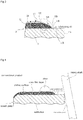
- Fig. 7 shows the main parts of the swash plate 2 in a third embodiment of the present invention.
- the third embodiment is obtained by a three-fold enlargement of the inner peripheral part 12A of the resin film layer 12 as compared to that of the second embodiment shown in Fig. 6 . Therefore, the curvature of the outline of the cross section, which is a slanted surface, has a larger approximately arc shape than the second embodiment does.
- the same reference numeral designates each member corresponding to the first embodiment.
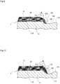
- Fig. 8 shows the main parts of the swash plate 2 in a fourth embodiment of the present invention.
- the inner peripheral part 12A of the resin film layer 12 acquires an approximately arc-shaped slanted surface, wherein its cross section in the radial direction is concave.
- the angle ⁇ 2 of the rising part 12D is smaller than the angle ⁇ 1, which is formed between the imaginary straight line L1 and the end face 11B.
- Fig. 9 shows the main parts of the swash plate 2 in a fifth embodiment of the present invention.
- an annular groove 11C is formed in a circumferential direction in a position adjacent to the inner peripheral part 12A of the resin film layer 12 at the end face 11B of the substrate 11.
- the bottom part of the annular groove 11C is a flat surface, the cross section of both side walls has a circular arc shape.
- the inner peripheral part 12A of the resin film layer 12 is shaped in such a way as to enter the interior of the annular groove 11C beyond one side wall of the annular groove 11C.
- the angles ⁇ 1 and ⁇ 2 become larger than those in the embodiments described above.
- Fig. 10 shows the main parts of the swash plate 2 in a sixth embodiment of the present invention.
- the sixth embodiment is an embodiment similar to the fifth embodiment shown in Fig. 9 wherein the cross sectional shape of the annular groove 11C of the fifth embodiment is formed in such a way so as to be arc-shaped.
- the inner peripheral part 12A of the resin film layer 12 is formed in such a way that it enters the annular groove 11C up to a position approximately in the center.
- Other parts of this arrangement are the same as in the fifth embodiment, and the same reference numeral designates each member corresponding to the fifth embodiment.
- the sixth embodiment it is also possible to obtain the same advantageous effects as the first embodiment.
- the resin film layer 12 is a coating layer
- a product other than a resin film layer may also be used as the coating layer.
- the present invention is a swash plate of a swash plate-type compressor and can be used as a swash plate having a coating layer that serves as a sliding layer
Description
- The present invention relates to a swash plate, more particularly, to a swash plate of a swash plate-type compressor, having a coating layer that serves as a sliding layer for the surface of the substrate.
- In the prior art, a swash plate with a resin film layer (coating layer) formed on the surface of a substrate, whereby the resin film layer serves as a sliding layer, has been proposed as a swash plate of a swash plate-type compressor (for
example Patent Literature 1 to Patent Literature 3). In this type of prior-art swash plate, a swash plate that is rotated by a rotary shaft slides with a shoe that serves as a mating member when the swash plate rotates, then lubricating oil is supplied from the inner peripheral side of the swash plate, and the sliding parts of both members are lubricated. - In
Patent Literature 4, a compressor swash plate (8), which is lead-free and is able to demonstrate a superior durability, includes a base member (81) and a sliding layer (82) being formed on the surface of the base member (81) and constituting at least a sliding surface (8a) for allowing a shoe (21) to slide thereon. The sliding layer (82) is formed by thermal spraying Cu-based-MnS by HVOF (High Velocity Oxygen Fuel) thermal spraying method. A method of manufacturing the said compressor swash plate. - In Patent Literature 5, A single-headed piston type swash-plate-operated refrigerant compressor is provided with a swash plate mounted on a rotatable drive shaft and having front and rear opposite surfaces, single headed pistons arranged on the rear side of the swash plate to reciprocate in respective cylinder bores, and front and rear shoes to be held in slide-contact with the peripheral parts of the front and rear surfaces of the swash plate to engage a tail end part of each of the single headed pistons with the swash plate in which the front and rear surfaces of the swash plate are provided with respective uppermost layers having physical surface properties different from one another.; A front uppermost and a rear uppermost layer of the swash plate are formed of a sprayed coating of, for example, a copper-base material and the rear uppermost layer is coated by a solid lubricant layer containing a solid lubricant, such as molybdenum disulfide, at least in a part of the solid lubricant. The thickness of the solid lubricant layer is measured and controlled by using the surface of the front layer as a reference plane.
-
- PTL 1: Japanese Laid Open Patent Publication No.
2002-317759 - PTL 2: Japanese Laid Open Patent Publication No.
2003-42061 - PTL 3: Japanese Laid Open Patent Publication No.
2003-184743 - PTL 4: European
Patent Application EP 1 985 856 A1 - PTL 5: European Patent Application
EP 0 926 340 A2 - When it comes to a prior-art swash plate having a resin film layer as described above, a problem arises when a lubricating oil is supplied to a surface of a sliding layer from the inner peripheral side of the swash plate, since it is difficult to supply the lubricating oil to the entire area of the surface of the sliding layer As is shown in
Fig. 4 andFig. 5 , in the prior-art swash plate, a resin film layer is formed on the surface of the substrate, whereby the substrate is exposed more on an inner side than on an inner peripheral part of the resin film layer. Moreover, the cross section in the radial direction of the inner peripheral part of the resin film layer has a step which rises by more than 40° with respect to the end face of the substrate. More specifically, there is an imaginary straight line L1 connecting an inner edge which is adjacent to the end face of the substrate in the inner peripheral part, and an outer edge which is adjacent to the surface of the sliding layer in the inner peripheral part, and an angle θ1 between the imaginary straight line L1 and the end face of the substrate is 40° or more. Furthermore, an angle θ2 between a rising part which is an adjacent section of the inner edge of the inner peripheral part and the end face of the substrate is an angle of approximately 90°. As a result, in the prior-art swash plate, when the lubricating oil is supplied from the inner peripheral side and moves to the surface of the sliding layer in a circumferential direction outward along the end face of the substrate on which the lubricating oil is exposed, the oil tends to be deflected back from the step of the inner peripheral part of the resin film layer (seeFig. 5 ). As a result, in the prior-art swash plate, a problem arises when the lubricating oil travels over the inner peripheral part of the resin film layer and is not properly supplied to the surface of the sliding layer in the radially outward direction. Therefore, the prior-art swash plate has been found to have a drawback, namely, that it tends to seize up due to insufficient lubrication. - Before this backdrop, the present invention provides a swash plate comprising a disc-shaped substrate, and a coating layer applied to a surface of the substrate, said coating layer serving as a sliding layer for the surface that slides along a shoe and has an inner peripheral part that serves as a slanted surface whose outer edge faces in a radially outwards direction, and the outer edge serves as a part on the inner peripheral part of the sliding layer with respect to an inner edge which is adjacent to an end face of the substrate, as a result of which the slanted surface is formed in such a way that an angle θ1 exists which is formed between an imaginary straight line connecting the inner edge and the outer edge of the sliding layer and the end face of the substrate which is set to 10° or less, and another angle θ2 exits which is formed between a tangent of the rising part adjacent to the inner edge and the end face and that is set to 20° or less, and another angle exits that is formed between the end face of the substrate and any given section of the slanted surface and that is less than 90°.
- In this arrangement, the inner peripheral part of the coating layer serves as the slanted surface as described above. As a result, when the lubricating oil is supplied from the inner peripheral side (of the substrate) of the swash plate, the oil travels over the inner peripheral part which serves as the slanted surface without being hindered, and is supplied to the outside of the sliding layers. Therefore, it is possible to prevent insufficient lubrication on the surface of the sliding layer, as a result of which the swash plate can be satisfactorily prevented from seizing up.
-
-
Fig. 1 is a front view of the main parts in a first embodiment of the present invention. -
Fig. 2 is a cross-sectional view showing the main parts of the swash plate shown inFig. 1 . -
Fig. 3 is an enlarged view of the main parts inFig. 2 . -
Fig. 4 is a cross-sectional view showing the main parts of a swash plate of a prior-art product. -
Fig. 5 is an enlarged view of the main parts inFig. 4 . -
Fig. 6 is a cross-sectional view of the main parts in a second embodiment of the present invention. -
Fig. 7 is a cross-sectional view of the main parts in a third embodiment of the present invention. -
Fig. 8 is a cross-sectional view of the main parts in a fourth embodiment of the present invention. -
Fig. 9 is a cross-sectional view of the main parts in a fifth embodiment of the present invention. -
Fig. 10 is a cross-sectional view of the main parts in a sixth embodiment of the present invention. - In order to explain the present invention with reference to the illustrated embodiments below,
Fig. 1 shows the main parts of a swash plate-type compressor. The swash plate-type compressor has a disc-shaped swash plate 2 that is attached in such a way as to be slanted towards an outer peripheral part of arotary shaft 1, a plurality ofpistons 3 is arranged along therotary shaft 1, and the outer peripheral part of theswash plate 2 is surrounded by acutout 3A at one end, and a plurality ofhemispherical shoes 4 is arranged between afront surface 2A andrear surface 2B of theswash plate 2 and a pair ofhemispherical recesses 3B, where 3B is formed within thecutout 3A of eachpiston 3. Theshoe 4 is arranged with ahemispherical surface 4A which engages with therecess 3B of thepiston 3, and aflat endface 4B which slides along thefront surface 2A or therear surface 2B, which are sliding layers of theswash plate 2. Theshoe 4 is made of SUJ2, welded to thehemispherical surface 4A andend face 4B and it subsequently undergoes a finishing process. When theswash plate 2 rotates due to the rotation of therotary shaft 1, thehemispherical surface 4A of a pair ofshoes 4 and therecesses piston 3 slide concurrently with the sliding of thefront surface 2A orrear surface 2B, which are sliding layers of theswash plate 2, and theend face 4B of a pair ofshoes 4, so that eachpiston 3 is configured so as to execute a reciprocating motion in the axial direction of therotary shaft 1. In addition, when therotary shaft 1 and theswash plate 2 rotate, lubricating oil is supplied from the inner peripheral part of theswash plate 2 through which therotary shaft 1 passes, and, during the rotation of theswash plate 2, the lubricating oil is supplied to thefront surface 2A andrear surface 2B, which are sliding layers. - As is shown in
Fig. 2 andFig. 3 , theswash plate 2 of the present embodiment comprises a disc-shaped substrate 11 with a through-hole 11A drilled in the center through which therotary shaft 1 passes, and aresin film layer 12 as a coating layer on eachend face 11 B of thesubstrate 11.Fig. 2 andFig. 3 only show theend face 11 B which serves as thefront surface 2A, and theresin film layer 12 which is applied thereto, whereby therear surface 2B is not shown here. Thesubstrate 11 is made of an iron-based material and is dimensioned with the same thickness throughout. The through-hole 11A in thesubstrate 11 serves as an inner peripheral part of theswash plate 2. Theresin film layer 12, as a coating layer, is configured to cover an area that extends further in an outer direction than the throughhole 11A from the outer peripheral part (outer peripheral part 2C of the swash plate 2) of theend face 11 B. Therefore, theend face 11 B which serves as an adjacent outer part of the throughhole 11A is exposed in a circumferential direction over the entire area. - In the present embodiment, whenever the
swash plate 2 comprises the arrangement described above, the innerperipheral part 12A of theresin film layer 12 is a slanted surface which the lubricating oil readily travels over and consequently, the lubricating oil can easily be supplied to thefront surface 2A and therear surface 2B, which are sliding layers. More specifically, in theresin film layer 12 of the present embodiment, the thickness of sections other than the innerperipheral part 12A and outer peripheral part are dimensioned with the same thickness, more specifically, between 2µm and 50µm. The innerperipheral part 12A serves as a slanted surface, whereby anouter edge 12C, which serves as a part of the inner peripheral edge of thesurface 2A (sliding layer), is located in a radially outwards direction with respect to aninner edge 12B which serves as a boundary with theend face 11B exposed on thesubstrate 11. In addition, an angle θ1, which is formed between an imaginary straight line L1 connecting theinner edge 12B and theouter edge 12C of the innerperipheral part 12A and theend face 11 B of thesubstrate 11 is set to 10° or less. In addition, an angle θ2, which is formed between the risingpart 12D adjacent to sections of theinner edge 12B and the end face , is set to 20° or less, and an angle formed between the end face of the substrate and any given section of the slanted surface and that is less than 90°. In order to obtain a more favorable effect, the angle θ1 is set to 5° or less and the angle θ2 is set to 15° or less. In addition, as a method for covering theend surface 11 B of thesubstrate 11 with theresin film layer 12, as described above, it is possible to use the following method that is to say, it is possible to employ spray coating, roll coating and stamp coating. Furthermore, it is even more preferable to form theresin film layer 12 by spin coating. In the case of spin coating, first a resin coating is applied onto both end faces 11 B of thesubstrate 11 by roll coating; subsequently, thesubstrate 11 is secured in a rotation machine and rotated at an appropriate rotational speed for a desired period of time. In this way, the resin coating flows to the outer peripheral side from the inner peripheral side of the end face of thesubstrate 11 by centrifugal force, and it is possible to form theresin film layer 12, which has the structure described above. - The
swash plate 2 of the present embodiment is structured as described above. In theswash plate 2 in the present embodiment as described above, the innerperipheral part 12A of theresin film layer 12 has a slanted surface which the lubricating oil can easily travel over. Therefore, when the lubricating oil is supplied from the throughhole 11A (inner peripheral part of the swash plate 2) of thesubstrate 11, the lubricating oil travels without any hindrance over the innerperipheral part 12A of theresin film layer 12 which serves as a slightly sloping slanted surface, and is supplied to thefront surface 2A as well as therear surface 2B (sliding layer), which are on the outside. Therefore, it is possible to prevent thefront surface 2A and therear surface 2B, which are sliding layers, from being insufficiently lubricated. As a result, it is possible to satisfactorily prevent theswash plate 2 from seizing up due to insufficient lubrication. -
Fig. 6 shows the main parts of theswash plate 2 in a second embodiment of the present invention. In the second embodiment, as compared to the first embodiment, the radial dimensions of the risingpart 12D are reduced, and an outline of a cross section in the radial direction of the innerperipheral part 12A is a slanted surface which is approximately arc-shaped. There is no change in other parts of this arrangement vis-à-vis the first embodiment shown inFig. 3 , and the same reference numeral designates each member corresponding to the first embodiment. In theswash plate 2 of the second embodiment as described above, it is also possible to obtain the same advantageous effects as the first embodiment. -
Fig. 7 shows the main parts of theswash plate 2 in a third embodiment of the present invention. The third embodiment is obtained by a three-fold enlargement of the innerperipheral part 12A of theresin film layer 12 as compared to that of the second embodiment shown inFig. 6 . Therefore, the curvature of the outline of the cross section, which is a slanted surface, has a larger approximately arc shape than the second embodiment does. There is no change in other parts of this arrangement vis-à-vis the first embodiment, and the same reference numeral designates each member corresponding to the first embodiment. In the third embodiment, it is also possible to obtain the same advantageous effects as the first embodiment. -
Fig. 8 shows the main parts of theswash plate 2 in a fourth embodiment of the present invention. In the fourth embodiment, the innerperipheral part 12A of theresin film layer 12 acquires an approximately arc-shaped slanted surface, wherein its cross section in the radial direction is concave. As a result, in the fourth embodiment, the angle θ2 of the risingpart 12D is smaller than the angle θ1, which is formed between the imaginary straight line L1 and theend face 11B. There is no change in other parts of this arrangement vis-à-vis the first embodiment shown inFig. 3 described above, and the same reference numeral designates each member corresponding to the first embodiment. In the fourth embodiment, it is also possible to obtain the same advantageous effects as the first embodiment. -
Fig. 9 shows the main parts of theswash plate 2 in a fifth embodiment of the present invention. In the fifth embodiment, an annular groove 11C is formed in a circumferential direction in a position adjacent to the innerperipheral part 12A of theresin film layer 12 at theend face 11B of thesubstrate 11. Although the bottom part of the annular groove 11C is a flat surface, the cross section of both side walls has a circular arc shape. In addition, the innerperipheral part 12A of theresin film layer 12 is shaped in such a way as to enter the interior of the annular groove 11C beyond one side wall of the annular groove 11C. In the fifth embodiment, in view of the shape of the annular groove 11C, the angles θ1 and θ2 become larger than those in the embodiments described above. There is no change in other parts of this arrangement vis-à-vis the first embodiment shown inFig. 3 described above, and the same reference numeral designates each member corresponding to the first embodiment. In the fifth embodiment, it is also possible to obtain the same advantageous effects as the first embodiment. -
Fig. 10 shows the main parts of theswash plate 2 in a sixth embodiment of the present invention. The sixth embodiment is an embodiment similar to the fifth embodiment shown inFig. 9 wherein the cross sectional shape of the annular groove 11C of the fifth embodiment is formed in such a way so as to be arc-shaped. In addition, the innerperipheral part 12A of theresin film layer 12 is formed in such a way that it enters the annular groove 11C up to a position approximately in the center. Other parts of this arrangement are the same as in the fifth embodiment, and the same reference numeral designates each member corresponding to the fifth embodiment. In the sixth embodiment, it is also possible to obtain the same advantageous effects as the first embodiment. Furthermore, in each embodiment described above, although it is assumed that theresin film layer 12 is a coating layer, a product other than a resin film layer may also be used as the coating layer. -
- 2
- swash plate
- 2A
- front surface (sliding layer)
- 2B
- rear surface (sliding layer)
- 12
- resin film layer (coating layer)
- 12A
- inner peripheral part
- 12B
- inner edge
- 12C
- outer edge
- 12D
- rising part
- The present invention is a swash plate of a swash plate-type compressor and can be used as a swash plate having a coating layer that serves as a sliding layer
Claims (5)
- A swash plate comprising: a disc-shaped substrate (11) and
a coating layer applied to a surface of the substrate, said coating layer serving as a sliding layer that slides along a shoe;
characterized in that
an inner peripheral part (12A) of the coating layer serves as a slanted surface whose outer edge faces in a radially outwards direction, and the outer edge serves as a part on the inner peripheral part of the sliding layer with respect to an inner edge which is adjacent to an end face of the substrate (11), as a result of which the slanted surface is formed in such a way that an angle θ1 exists which is formed between an imaginary straight line (L1) connecting the inner edge (12B) and the outer edge (12C) of the sliding layer (12), and the end face (11B) of the substrate (11), that is set to 10° or less, and another angle θ2 exists which is formed between a rising part (12D) adjacent to the inner edge (12B) and the end face (11B) of the substrate that is set to 20° or less, and another angle exists that is formed between the end face (11B) of the substrate (11) and any given section of the slanted surface and that is less than 90°. - The swash plate according to claim 1,
characterized in that the coating layer comprises a resin film layer (12) and the angle θ1 is set to 5° or less and the angle θ2 is set to 15° or less. - The swash plate according to claim 1 or claim 2,
characterized in that the slanted surface has a cross section that widens in the radial direction upwards so as to be approximately arc-shaped, or has an arc-shaped cross section that is concave in the radial direction. - The swash plate according to claim 1;
characterized in that an annular shaped groove (11c) in the circumferential direction is formed on an end face that serves as an adjacent inner part of the coating layer, and the inner peripheral part (12A) of the coating layer is formed to enter the annular shaped groove. - The swash plate according to one of claims 1 to 4,
characterized in that a thickness of the coating layer is set from 2µm to 50µm.
Applications Claiming Priority (2)
| Application Number | Priority Date | Filing Date | Title |
|---|---|---|---|
| JP2012077531A JP5810020B2 (en) | 2012-03-29 | 2012-03-29 | Swash plate |
| PCT/JP2013/058583 WO2013146682A1 (en) | 2012-03-29 | 2013-03-25 | Swash plate |
Publications (3)
| Publication Number | Publication Date |
|---|---|
| EP2832997A1 EP2832997A1 (en) | 2015-02-04 |
| EP2832997A4 EP2832997A4 (en) | 2016-03-30 |
| EP2832997B1 true EP2832997B1 (en) | 2017-05-10 |
Family
ID=49259933
Family Applications (1)
| Application Number | Title | Priority Date | Filing Date |
|---|---|---|---|
| EP13769325.5A Active EP2832997B1 (en) | 2012-03-29 | 2013-03-25 | Swash plate |
Country Status (7)
| Country | Link |
|---|---|
| US (1) | US9206890B2 (en) |
| EP (1) | EP2832997B1 (en) |
| JP (1) | JP5810020B2 (en) |
| KR (1) | KR20140132012A (en) |
| CN (1) | CN104246225B (en) |
| HU (1) | HUE035394T2 (en) |
| WO (1) | WO2013146682A1 (en) |
Families Citing this family (5)
| Publication number | Priority date | Publication date | Assignee | Title |
|---|---|---|---|---|
| CN106536928B (en) * | 2014-07-23 | 2020-07-14 | Ntn株式会社 | Semi-spherical sliding shoe of swash plate type compressor and swash plate type compressor |
| JP6178354B2 (en) * | 2015-02-27 | 2017-08-09 | 大豊工業株式会社 | Plain bearing |
| US10466061B2 (en) * | 2016-12-30 | 2019-11-05 | Nio Usa, Inc. | Autonomous override safety |
| US10440536B2 (en) * | 2017-05-19 | 2019-10-08 | Waymo Llc | Early boarding of passengers in autonomous vehicles |
| JP2022149496A (en) * | 2021-03-25 | 2022-10-07 | 大同メタル工業株式会社 | Slide member |
Family Cites Families (11)
| Publication number | Priority date | Publication date | Assignee | Title |
|---|---|---|---|---|
| JPH11193780A (en) * | 1997-12-26 | 1999-07-21 | Toyota Autom Loom Works Ltd | Single-headed piston swash plate type compression machine and method for manufacturing swash plate |
| JP2002021719A (en) * | 2000-07-12 | 2002-01-23 | Toyota Industries Corp | Wash plate for compressor |
| JP2002257042A (en) * | 2001-02-28 | 2002-09-11 | Toyota Industries Corp | Object component for forming lubricating surface in compressor |
| JP2002317759A (en) | 2001-04-25 | 2002-10-31 | Toyota Industries Corp | Shoe for swash plate-type compressor and swash plate- type compressor having the same |
| JP3948259B2 (en) | 2001-05-21 | 2007-07-25 | 株式会社豊田自動織機 | Shoe for a swash plate compressor and manufacturing method thereof |
| JP2003042061A (en) | 2001-05-21 | 2003-02-13 | Toyota Industries Corp | Swash plate compressor |
| JP2003120520A (en) * | 2001-10-05 | 2003-04-23 | Sanden Corp | Swash plate type compressor |
| JP2003184743A (en) | 2001-12-12 | 2003-07-03 | Toyota Industries Corp | Shoe for swash plate type compressor and swash type compressor provided therewith |
| WO2007091564A1 (en) * | 2006-02-06 | 2007-08-16 | Ntn Corporation | Swash plate for swash plate-type compressor and swash plate-type compressor |
| JP2008274762A (en) * | 2007-04-25 | 2008-11-13 | Toyota Industries Corp | Compressor swash plate, and method of manufacturing the same |
| JP5841471B2 (en) * | 2012-03-26 | 2016-01-13 | 大豊工業株式会社 | Swash plate |
-
2012
- 2012-03-29 JP JP2012077531A patent/JP5810020B2/en active Active
-
2013
- 2013-03-25 US US14/387,869 patent/US9206890B2/en active Active
- 2013-03-25 WO PCT/JP2013/058583 patent/WO2013146682A1/en active Application Filing
- 2013-03-25 EP EP13769325.5A patent/EP2832997B1/en active Active
- 2013-03-25 KR KR1020147030196A patent/KR20140132012A/en not_active Application Discontinuation
- 2013-03-25 CN CN201380017610.6A patent/CN104246225B/en active Active
- 2013-03-25 HU HUE13769325A patent/HUE035394T2/en unknown
Also Published As
| Publication number | Publication date |
|---|---|
| US9206890B2 (en) | 2015-12-08 |
| EP2832997A4 (en) | 2016-03-30 |
| JP2013204574A (en) | 2013-10-07 |
| CN104246225B (en) | 2016-06-29 |
| EP2832997A1 (en) | 2015-02-04 |
| KR20140132012A (en) | 2014-11-14 |
| US20150033884A1 (en) | 2015-02-05 |
| JP5810020B2 (en) | 2015-11-11 |
| WO2013146682A1 (en) | 2013-10-03 |
| CN104246225A (en) | 2014-12-24 |
| HUE035394T2 (en) | 2018-05-02 |
Similar Documents
| Publication | Publication Date | Title |
|---|---|---|
| EP2832997B1 (en) | Swash plate | |
| EP2963304B1 (en) | Spherical plain bearing with inner sleeve | |
| KR102156455B1 (en) | Thrust washer | |
| JP6231781B2 (en) | Different thickness coatings for cylinder liners | |
| US9909615B2 (en) | Thrust bearing and bearing device for crankshaft of internal combustion engine | |
| JP5465297B2 (en) | Ball bearing cage | |
| CN104126076A (en) | Thermal spray coating for connecting rod small end | |
| US20210207590A1 (en) | Pump body assembly, fluid machinery, and heat exchange device | |
| JP6263545B2 (en) | Sliding bearing provided with bearing substrate and polymer embedded body, and engine provided with the same | |
| US20170058942A1 (en) | Bearing device for crankshaft of internal combustion engine | |
| KR20110007587A (en) | Bearing for a connecting rod | |
| EP2832995B1 (en) | Swash plate | |
| EP3159563A1 (en) | Plain bearing | |
| CN105781869B (en) | Piston unit and hydrostatic radial piston machine | |
| EP2290239B1 (en) | Shoe | |
| JP6653115B2 (en) | Thrust roller bearing with race | |
| JP6466754B2 (en) | Swash plate compressor hemispherical shoe and swash plate compressor | |
| JP2022186410A (en) | Swash plate for compressor and swash plate type compressor | |
| JP2009257202A (en) | Shoe | |
| JP2010071115A (en) | Shoe | |
| JP2019124233A (en) | Connecting rod bearing for crank shaft of internal combustion engine | |
| JP2010048157A (en) | Shoe | |
| JP2006022846A (en) | Retainer for thrust roller bearing and thrust roller bearing | |
| JP2010048156A (en) | Shoe |
Legal Events
| Date | Code | Title | Description |
|---|---|---|---|
| PUAI | Public reference made under article 153(3) epc to a published international application that has entered the european phase |
Free format text: ORIGINAL CODE: 0009012 |
|
| 17P | Request for examination filed |
Effective date: 20141029 |
|
| AK | Designated contracting states |
Kind code of ref document: A1 Designated state(s): AL AT BE BG CH CY CZ DE DK EE ES FI FR GB GR HR HU IE IS IT LI LT LU LV MC MK MT NL NO PL PT RO RS SE SI SK SM TR |
|
| AX | Request for extension of the european patent |
Extension state: BA ME |
|
| DAX | Request for extension of the european patent (deleted) | ||
| REG | Reference to a national code |
Ref country code: DE Ref legal event code: R079 Ref document number: 602013021002 Country of ref document: DE Free format text: PREVIOUS MAIN CLASS: F04B0039020000 Ipc: F04B0027080000 |
|
| RA4 | Supplementary search report drawn up and despatched (corrected) |
Effective date: 20160225 |
|
| RIC1 | Information provided on ipc code assigned before grant |
Ipc: F04B 39/02 20060101ALI20160219BHEP Ipc: F04B 27/10 20060101ALI20160219BHEP Ipc: F16C 33/20 20060101ALI20160219BHEP Ipc: F16C 33/66 20060101ALI20160219BHEP Ipc: F16H 23/00 20060101ALI20160219BHEP Ipc: F16C 17/04 20060101ALI20160219BHEP Ipc: F16C 33/10 20060101ALI20160219BHEP Ipc: F04B 27/08 20060101AFI20160219BHEP |
|
| GRAP | Despatch of communication of intention to grant a patent |
Free format text: ORIGINAL CODE: EPIDOSNIGR1 |
|
| STAA | Information on the status of an ep patent application or granted ep patent |
Free format text: STATUS: GRANT OF PATENT IS INTENDED |
|
| INTG | Intention to grant announced |
Effective date: 20161202 |
|
| GRAS | Grant fee paid |
Free format text: ORIGINAL CODE: EPIDOSNIGR3 |
|
| GRAA | (expected) grant |
Free format text: ORIGINAL CODE: 0009210 |
|
| STAA | Information on the status of an ep patent application or granted ep patent |
Free format text: STATUS: THE PATENT HAS BEEN GRANTED |
|
| RAP1 | Party data changed (applicant data changed or rights of an application transferred) |
Owner name: TAIHO KOGYO CO., LTD. |
|
| AK | Designated contracting states |
Kind code of ref document: B1 Designated state(s): AL AT BE BG CH CY CZ DE DK EE ES FI FR GB GR HR HU IE IS IT LI LT LU LV MC MK MT NL NO PL PT RO RS SE SI SK SM TR |
|
| REG | Reference to a national code |
Ref country code: GB Ref legal event code: FG4D |
|
| REG | Reference to a national code |
Ref country code: AT Ref legal event code: REF Ref document number: 892644 Country of ref document: AT Kind code of ref document: T Effective date: 20170515 Ref country code: CH Ref legal event code: EP |
|
| REG | Reference to a national code |
Ref country code: IE Ref legal event code: FG4D |
|
| REG | Reference to a national code |
Ref country code: DE Ref legal event code: R096 Ref document number: 602013021002 Country of ref document: DE |
|
| REG | Reference to a national code |
Ref country code: NL Ref legal event code: MP Effective date: 20170510 |
|
| REG | Reference to a national code |
Ref country code: LT Ref legal event code: MG4D |
|
| REG | Reference to a national code |
Ref country code: AT Ref legal event code: MK05 Ref document number: 892644 Country of ref document: AT Kind code of ref document: T Effective date: 20170510 |
|
| PG25 | Lapsed in a contracting state [announced via postgrant information from national office to epo] |
Ref country code: GR Free format text: LAPSE BECAUSE OF FAILURE TO SUBMIT A TRANSLATION OF THE DESCRIPTION OR TO PAY THE FEE WITHIN THE PRESCRIBED TIME-LIMIT Effective date: 20170811 Ref country code: FI Free format text: LAPSE BECAUSE OF FAILURE TO SUBMIT A TRANSLATION OF THE DESCRIPTION OR TO PAY THE FEE WITHIN THE PRESCRIBED TIME-LIMIT Effective date: 20170510 Ref country code: NO Free format text: LAPSE BECAUSE OF FAILURE TO SUBMIT A TRANSLATION OF THE DESCRIPTION OR TO PAY THE FEE WITHIN THE PRESCRIBED TIME-LIMIT Effective date: 20170810 Ref country code: HR Free format text: LAPSE BECAUSE OF FAILURE TO SUBMIT A TRANSLATION OF THE DESCRIPTION OR TO PAY THE FEE WITHIN THE PRESCRIBED TIME-LIMIT Effective date: 20170510 Ref country code: ES Free format text: LAPSE BECAUSE OF FAILURE TO SUBMIT A TRANSLATION OF THE DESCRIPTION OR TO PAY THE FEE WITHIN THE PRESCRIBED TIME-LIMIT Effective date: 20170510 Ref country code: AT Free format text: LAPSE BECAUSE OF FAILURE TO SUBMIT A TRANSLATION OF THE DESCRIPTION OR TO PAY THE FEE WITHIN THE PRESCRIBED TIME-LIMIT Effective date: 20170510 Ref country code: LT Free format text: LAPSE BECAUSE OF FAILURE TO SUBMIT A TRANSLATION OF THE DESCRIPTION OR TO PAY THE FEE WITHIN THE PRESCRIBED TIME-LIMIT Effective date: 20170510 |
|
| PG25 | Lapsed in a contracting state [announced via postgrant information from national office to epo] |
Ref country code: SE Free format text: LAPSE BECAUSE OF FAILURE TO SUBMIT A TRANSLATION OF THE DESCRIPTION OR TO PAY THE FEE WITHIN THE PRESCRIBED TIME-LIMIT Effective date: 20170510 Ref country code: IS Free format text: LAPSE BECAUSE OF FAILURE TO SUBMIT A TRANSLATION OF THE DESCRIPTION OR TO PAY THE FEE WITHIN THE PRESCRIBED TIME-LIMIT Effective date: 20170910 Ref country code: BG Free format text: LAPSE BECAUSE OF FAILURE TO SUBMIT A TRANSLATION OF THE DESCRIPTION OR TO PAY THE FEE WITHIN THE PRESCRIBED TIME-LIMIT Effective date: 20170810 Ref country code: NL Free format text: LAPSE BECAUSE OF FAILURE TO SUBMIT A TRANSLATION OF THE DESCRIPTION OR TO PAY THE FEE WITHIN THE PRESCRIBED TIME-LIMIT Effective date: 20170510 Ref country code: PL Free format text: LAPSE BECAUSE OF FAILURE TO SUBMIT A TRANSLATION OF THE DESCRIPTION OR TO PAY THE FEE WITHIN THE PRESCRIBED TIME-LIMIT Effective date: 20170510 Ref country code: LV Free format text: LAPSE BECAUSE OF FAILURE TO SUBMIT A TRANSLATION OF THE DESCRIPTION OR TO PAY THE FEE WITHIN THE PRESCRIBED TIME-LIMIT Effective date: 20170510 Ref country code: RS Free format text: LAPSE BECAUSE OF FAILURE TO SUBMIT A TRANSLATION OF THE DESCRIPTION OR TO PAY THE FEE WITHIN THE PRESCRIBED TIME-LIMIT Effective date: 20170510 |
|
| PG25 | Lapsed in a contracting state [announced via postgrant information from national office to epo] |
Ref country code: CZ Free format text: LAPSE BECAUSE OF FAILURE TO SUBMIT A TRANSLATION OF THE DESCRIPTION OR TO PAY THE FEE WITHIN THE PRESCRIBED TIME-LIMIT Effective date: 20170510 Ref country code: EE Free format text: LAPSE BECAUSE OF FAILURE TO SUBMIT A TRANSLATION OF THE DESCRIPTION OR TO PAY THE FEE WITHIN THE PRESCRIBED TIME-LIMIT Effective date: 20170510 Ref country code: SK Free format text: LAPSE BECAUSE OF FAILURE TO SUBMIT A TRANSLATION OF THE DESCRIPTION OR TO PAY THE FEE WITHIN THE PRESCRIBED TIME-LIMIT Effective date: 20170510 Ref country code: RO Free format text: LAPSE BECAUSE OF FAILURE TO SUBMIT A TRANSLATION OF THE DESCRIPTION OR TO PAY THE FEE WITHIN THE PRESCRIBED TIME-LIMIT Effective date: 20170510 Ref country code: DK Free format text: LAPSE BECAUSE OF FAILURE TO SUBMIT A TRANSLATION OF THE DESCRIPTION OR TO PAY THE FEE WITHIN THE PRESCRIBED TIME-LIMIT Effective date: 20170510 |
|
| REG | Reference to a national code |
Ref country code: DE Ref legal event code: R097 Ref document number: 602013021002 Country of ref document: DE |
|
| PG25 | Lapsed in a contracting state [announced via postgrant information from national office to epo] |
Ref country code: SM Free format text: LAPSE BECAUSE OF FAILURE TO SUBMIT A TRANSLATION OF THE DESCRIPTION OR TO PAY THE FEE WITHIN THE PRESCRIBED TIME-LIMIT Effective date: 20170510 Ref country code: IT Free format text: LAPSE BECAUSE OF FAILURE TO SUBMIT A TRANSLATION OF THE DESCRIPTION OR TO PAY THE FEE WITHIN THE PRESCRIBED TIME-LIMIT Effective date: 20170510 |
|
| PLBE | No opposition filed within time limit |
Free format text: ORIGINAL CODE: 0009261 |
|
| STAA | Information on the status of an ep patent application or granted ep patent |
Free format text: STATUS: NO OPPOSITION FILED WITHIN TIME LIMIT |
|
| 26N | No opposition filed |
Effective date: 20180213 |
|
| REG | Reference to a national code |
Ref country code: HU Ref legal event code: AG4A Ref document number: E035394 Country of ref document: HU |
|
| PG25 | Lapsed in a contracting state [announced via postgrant information from national office to epo] |
Ref country code: SI Free format text: LAPSE BECAUSE OF FAILURE TO SUBMIT A TRANSLATION OF THE DESCRIPTION OR TO PAY THE FEE WITHIN THE PRESCRIBED TIME-LIMIT Effective date: 20170510 |
|
| REG | Reference to a national code |
Ref country code: CH Ref legal event code: PL |
|
| GBPC | Gb: european patent ceased through non-payment of renewal fee |
Effective date: 20180325 |
|
| PG25 | Lapsed in a contracting state [announced via postgrant information from national office to epo] |
Ref country code: MC Free format text: LAPSE BECAUSE OF FAILURE TO SUBMIT A TRANSLATION OF THE DESCRIPTION OR TO PAY THE FEE WITHIN THE PRESCRIBED TIME-LIMIT Effective date: 20170510 |
|
| REG | Reference to a national code |
Ref country code: BE Ref legal event code: MM Effective date: 20180331 |
|
| REG | Reference to a national code |
Ref country code: IE Ref legal event code: MM4A |
|
| PG25 | Lapsed in a contracting state [announced via postgrant information from national office to epo] |
Ref country code: LU Free format text: LAPSE BECAUSE OF NON-PAYMENT OF DUE FEES Effective date: 20180325 |
|
| PG25 | Lapsed in a contracting state [announced via postgrant information from national office to epo] |
Ref country code: IE Free format text: LAPSE BECAUSE OF NON-PAYMENT OF DUE FEES Effective date: 20180325 Ref country code: HU Free format text: LAPSE BECAUSE OF NON-PAYMENT OF DUE FEES Effective date: 20180326 |
|
| PG25 | Lapsed in a contracting state [announced via postgrant information from national office to epo] |
Ref country code: BE Free format text: LAPSE BECAUSE OF NON-PAYMENT OF DUE FEES Effective date: 20180331 Ref country code: GB Free format text: LAPSE BECAUSE OF NON-PAYMENT OF DUE FEES Effective date: 20180325 Ref country code: CH Free format text: LAPSE BECAUSE OF NON-PAYMENT OF DUE FEES Effective date: 20180331 Ref country code: LI Free format text: LAPSE BECAUSE OF NON-PAYMENT OF DUE FEES Effective date: 20180331 |
|
| PG25 | Lapsed in a contracting state [announced via postgrant information from national office to epo] |
Ref country code: FR Free format text: LAPSE BECAUSE OF NON-PAYMENT OF DUE FEES Effective date: 20180331 |
|
| PG25 | Lapsed in a contracting state [announced via postgrant information from national office to epo] |
Ref country code: MT Free format text: LAPSE BECAUSE OF NON-PAYMENT OF DUE FEES Effective date: 20180325 |
|
| PG25 | Lapsed in a contracting state [announced via postgrant information from national office to epo] |
Ref country code: TR Free format text: LAPSE BECAUSE OF FAILURE TO SUBMIT A TRANSLATION OF THE DESCRIPTION OR TO PAY THE FEE WITHIN THE PRESCRIBED TIME-LIMIT Effective date: 20170510 |
|
| PG25 | Lapsed in a contracting state [announced via postgrant information from national office to epo] |
Ref country code: PT Free format text: LAPSE BECAUSE OF FAILURE TO SUBMIT A TRANSLATION OF THE DESCRIPTION OR TO PAY THE FEE WITHIN THE PRESCRIBED TIME-LIMIT Effective date: 20170510 |
|
| PG25 | Lapsed in a contracting state [announced via postgrant information from national office to epo] |
Ref country code: MK Free format text: LAPSE BECAUSE OF NON-PAYMENT OF DUE FEES Effective date: 20170510 Ref country code: CY Free format text: LAPSE BECAUSE OF FAILURE TO SUBMIT A TRANSLATION OF THE DESCRIPTION OR TO PAY THE FEE WITHIN THE PRESCRIBED TIME-LIMIT Effective date: 20170510 |
|
| PG25 | Lapsed in a contracting state [announced via postgrant information from national office to epo] |
Ref country code: AL Free format text: LAPSE BECAUSE OF FAILURE TO SUBMIT A TRANSLATION OF THE DESCRIPTION OR TO PAY THE FEE WITHIN THE PRESCRIBED TIME-LIMIT Effective date: 20170510 |
|
| PGFP | Annual fee paid to national office [announced via postgrant information from national office to epo] |
Ref country code: DE Payment date: 20230131 Year of fee payment: 11 |