EP2832640A1 - Composite flexure for tiltrotor rotor system - Google Patents
Composite flexure for tiltrotor rotor system Download PDFInfo
- Publication number
- EP2832640A1 EP2832640A1 EP20130199603 EP13199603A EP2832640A1 EP 2832640 A1 EP2832640 A1 EP 2832640A1 EP 20130199603 EP20130199603 EP 20130199603 EP 13199603 A EP13199603 A EP 13199603A EP 2832640 A1 EP2832640 A1 EP 2832640A1
- Authority
- EP
- European Patent Office
- Prior art keywords
- composite
- flexure
- composite flexure
- rotor blade
- coupled
- Prior art date
- Legal status (The legal status is an assumption and is not a legal conclusion. Google has not performed a legal analysis and makes no representation as to the accuracy of the status listed.)
- Granted
Links
- 239000002131 composite material Substances 0.000 title claims abstract description 116
- 230000002787 reinforcement Effects 0.000 claims description 24
- 239000000463 material Substances 0.000 claims description 16
- 230000004044 response Effects 0.000 claims description 8
- 238000004891 communication Methods 0.000 claims description 7
- 238000005452 bending Methods 0.000 claims description 6
- 239000011159 matrix material Substances 0.000 claims description 2
- 230000008901 benefit Effects 0.000 description 6
- 230000008878 coupling Effects 0.000 description 6
- 238000010168 coupling process Methods 0.000 description 6
- 238000005859 coupling reaction Methods 0.000 description 6
- 230000033001 locomotion Effects 0.000 description 5
- 239000013536 elastomeric material Substances 0.000 description 3
- RZVHIXYEVGDQDX-UHFFFAOYSA-N 9,10-anthraquinone Chemical compound C1=CC=C2C(=O)C3=CC=CC=C3C(=O)C2=C1 RZVHIXYEVGDQDX-UHFFFAOYSA-N 0.000 description 2
- 230000003534 oscillatory effect Effects 0.000 description 2
- 229920000642 polymer Polymers 0.000 description 2
- 230000009471 action Effects 0.000 description 1
- 238000007792 addition Methods 0.000 description 1
- 230000004075 alteration Effects 0.000 description 1
- 230000000712 assembly Effects 0.000 description 1
- 238000000429 assembly Methods 0.000 description 1
- 230000005540 biological transmission Effects 0.000 description 1
- 230000008859 change Effects 0.000 description 1
- 239000000470 constituent Substances 0.000 description 1
- 230000003247 decreasing effect Effects 0.000 description 1
- 230000000694 effects Effects 0.000 description 1
- 239000003822 epoxy resin Substances 0.000 description 1
- 239000000835 fiber Substances 0.000 description 1
- 239000011152 fibreglass Substances 0.000 description 1
- 238000000034 method Methods 0.000 description 1
- 238000012986 modification Methods 0.000 description 1
- 230000004048 modification Effects 0.000 description 1
- 229920000647 polyepoxide Polymers 0.000 description 1
- 238000009987 spinning Methods 0.000 description 1
- 238000006467 substitution reaction Methods 0.000 description 1
- 229920001187 thermosetting polymer Polymers 0.000 description 1
- 230000007704 transition Effects 0.000 description 1
Images


Classifications
-
- B—PERFORMING OPERATIONS; TRANSPORTING
- B64—AIRCRAFT; AVIATION; COSMONAUTICS
- B64C—AEROPLANES; HELICOPTERS
- B64C27/00—Rotorcraft; Rotors peculiar thereto
- B64C27/32—Rotors
- B64C27/33—Rotors having flexing arms
-
- B—PERFORMING OPERATIONS; TRANSPORTING
- B64—AIRCRAFT; AVIATION; COSMONAUTICS
- B64C—AEROPLANES; HELICOPTERS
- B64C27/00—Rotorcraft; Rotors peculiar thereto
- B64C27/32—Rotors
- B64C27/46—Blades
- B64C27/473—Constructional features
- B64C27/48—Root attachment to rotor head
-
- B—PERFORMING OPERATIONS; TRANSPORTING
- B64—AIRCRAFT; AVIATION; COSMONAUTICS
- B64C—AEROPLANES; HELICOPTERS
- B64C29/00—Aircraft capable of landing or taking-off vertically, e.g. vertical take-off and landing [VTOL] aircraft
- B64C29/0008—Aircraft capable of landing or taking-off vertically, e.g. vertical take-off and landing [VTOL] aircraft having its flight directional axis horizontal when grounded
- B64C29/0016—Aircraft capable of landing or taking-off vertically, e.g. vertical take-off and landing [VTOL] aircraft having its flight directional axis horizontal when grounded the lift during taking-off being created by free or ducted propellers or by blowers
- B64C29/0033—Aircraft capable of landing or taking-off vertically, e.g. vertical take-off and landing [VTOL] aircraft having its flight directional axis horizontal when grounded the lift during taking-off being created by free or ducted propellers or by blowers the propellers being tiltable relative to the fuselage
Definitions
- This invention relates generally to tiltrotor aircraft, and more particularly, to a composite flexure for a tiltrotor rotor system.
- a rotorcraft may include one or more rotor systems.
- a rotorcraft rotor system is a main rotor system.
- a main rotor system may generate aerodynamic lift to support the weight of the rotorcraft in flight and thrust to counteract aerodynamic drag and move the rotorcraft in forward flight.
- Another example of a rotorcraft rotor system is a tail rotor system.
- a tail rotor system may generate thrust in the same direction as the main rotor system's rotation to counter the torque effect created by the main rotor system.
- a technical advantage of one embodiment may include the capability to accommodate various forces imparted on a tiltrotor rotor system without the use of elastomeric bearings.
- a technical advantage of one embodiment may include the capability to reduce the size of tiltrotor blades by eliminating at least some elastomeric bearings located within the blades.
- FIGURE 1 shows a rotorcraft 100 according to one example embodiment.
- Rotorcraft 100 features rotor systems 110a and 110b, blades 120, a fuselage 130, a landing gear 140, and a wing 150.
- Rotor system 110 may rotate blades 120.
- Rotor system 110 may include a control system for selectively controlling the pitch of each blade 120 in order to selectively control direction, thrust, and lift of rotorcraft 100.
- rotorcraft 100 represents a tiltrotor aircraft
- rotor systems 110a and 110b feature rotatable nacelles.
- the position of nacelles 110a and 110b, as well as the pitch of rotor blades 120, can be selectively controlled in order to selectively control direction, thrust, and lift of tiltrotor aircraft 100.
- Fuselage 130 represents the main body of rotorcraft 100 and may be coupled to rotor system 110 (e.g., via wing 150) such that rotor system 110 and blades 120 may move fuselage 130 through the air.
- Landing gear 140 supports rotorcraft 100 when rotorcraft 100 is landing and/or when rotorcraft 100 is at rest on the ground.
- Teachings of certain embodiments relating to rotor systems described herein may apply to rotor system 110 and/or other rotor systems, such as non-tilting rotor and helicopter rotor systems. It should also be appreciated that teachings from rotorcraft 100 may apply to aircraft other than rotorcraft, such as airplanes and unmanned aircraft, to name a few examples.
- tiltrotor aircraft 100 may operate in a helicopter mode by tilting the nacelles upright and in an airplane mode by tilting the nacelles forward. Tiltrotor aircraft 100 may generate greater forward speed in airplane mode than in helicopter mode because, in airplane mode, blades 120 are oriented to generate greater thrust propelling the aircraft forward (somewhat analogous to a propeller).
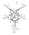
- FIGURE 2 shows a simplified example of a rotor system 110 that may be incorporated in whole or in part in the rotorcraft 100 of FIGURE 1.
- rotor system 110 features a power train 112, a yoke 114, a swashplate 116, and pitch links 118.
- rotor system 110 may include more or fewer components.
- FIGURE 2 does not show components such as a gearbox, drive links, drive levers, tilting devices, and other components that may be incorporated.
- Power train 112 features a power source 112a and a drive shaft 112b.
- Power source 112a, drive shaft 112b, and yoke 114 are mechanical components for transmitting torque and/or rotation.
- Power train 112 may include a variety of components, including an engine, a transmission, and differentials.
- drive shaft 112b receives torque or rotational energy from power source 112a and rotates yoke 114. Rotation of rotor yoke 114 causes blades 120 to rotate about drive shaft 112b.
- power train 112 may include more or fewer components.
- tilting devices may be provided in mechanical communication with power train 112 that allows certain components of rotor system 110 to tilt between helicopter mode and airplane mode.
- Swashplate 116 translates rotorcraft flight control input into motion of blades 120. Because blades 120 are typically spinning when the rotorcraft is in flight, swashplate 116 may transmit flight control input from the non-rotating fuselage to the yoke 114, blades 120, and/or components coupling yoke 114 to blades 120 (e.g., grips and pitch horns). References in this description to coupling between a pitch link and a yoke may also include, but are not limited to, coupling between a pitch link and a blade or components coupling a yoke to a blade.
- swashplate 116 may include a non-rotating swashplate ring 116a and a rotating swashplate ring 116b.
- Non-rotating swashplate ring 116a does not rotate with drive shaft 112b
- rotating swashplate ring 116b does rotate with drive shaft 112b.
- pitch links 118 connect rotating swashplate ring 116b to blades 120.
- translating the non-rotating swashplate ring 116a along the axis of drive shaft 112b causes the pitch links 118 to move up or down. This changes the pitch angle of all blades 120 equally, increasing or decreasing the thrust of the rotor and causing the aircraft to ascend or descend. Tilting the non-rotating swashplate ring 116a causes the rotating swashplate 116b to tilt, moving the pitch links 118 up and down cyclically as they rotate with the drive shaft. This tilts the thrust vector of the rotor, causing rotorcraft 100 to translate horizontally following the direction the swashplate is tilted.
- rotor system 110 may be subject to a variety of forces.
- the weight of blades 120 and the lift of blades 120 may result in transverse forces on yoke 114 and other components.
- Two examples of transverse forces may include forces resulting from flapping and coning of blades 120.
- Flapping may generally refer to the up-and-down movement of a rotor blade positioned at a right angle to the plane of rotation.
- Coning may generally refer to the upward flexing of a rotor blade due to lift forces acting on the rotor blade.
- rotor system 110 may be subject to other forces, such as axial, lead/lag, and feathering forces.
- Axial forces may general refer to forces on rotor system 110 resulting from the centrifugal force on the rotor blades during rotation of the rotor blades.
- Lead and lag forces may generally refer to forces resulting from the horizontal movement of rotor blades about a vertical pin. Lead and lag forces may occur, for example, if blades 120 do not rotate faster or slower than the rotation of yoke 114.
- Feathering forces may generally refer to forces resulting from twisting motions that cause a rotor blade to change pitch.
- an elastomeric material may be provided to reduce rotor fatigue.
- An elastomeric material is a material, such as a polymer, having the property of viscoelasticity (colloquially, "elasticity").
- An example of an elastomeric material is rubber.
- Elastomeric materials generally have a low Young's modulus and a high yield strain when compared to other materials. Elastomeric materials are typically thermosets having long polymer chains that cross-link during curing (i.e., vulcanizing).
- elastomeric bearing assemblies in a rotor system such as rotor system 110, however, may create some design issues. For example, applying forces against an elastomeric bearing may generate a considerable amount of heat. In addition, elastomeric materials may be prone failure during tension and torsion. Accordingly, elastomeric bearings may be sized large enough to dissipate heat appropriately and to withstand the tension and torsion forces that may occur during operation of rotor system 110. Large elastomeric bearing packages, however, may increase the size of various components of rotor system 110 and blades 120. For example, yoke 114 should be large enough to accommodate the elastomeric bearing package.
- the elastomeric bearing package may be located inside an interior portion of a blade 120.
- a larger elastomeric bearing package may require a thicker blade 120, which may reduce the aerodynamic effectiveness of the blade 120.
- teachings of certain embodiments recognize the capability to accommodate various forces imparted on rotor system 110 without the use of elastomeric bearings.
- teachings of certain embodiments recognize the capability of a composite flexure to accommodate various forces imparted on rotor system 110.
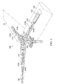
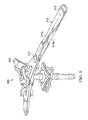
- FIGURES 3-6 show a rotor system 200 according to one example embodiment.
- FIGURE 3 shows a perspective view of rotor system 200 with blades 120 installed (blades 120 are shown as partially transparent for clarity).
- FIGURE 4 shows a top view of rotor system 200 with blades 120 installed (blades 120 are shown as partially transparent for clarity).
- FIGURES 5 and 6 show perspective views of rotor system 200 with blades 120 removed.
- rotor system 200 features a composite flexure 210 and a yoke 220.
- Composite flexure features composite flexure members 210a and 210b.
- each blade 120 is coupled to composite flexure member 210 at an attachment plane 212 at one end of composite flexure member 210
- yoke 220 is coupled to composite flexure member 210 at an attachment plane 214 at the opposite end of composite flexure member 210.
- Composite flexure 210 and/or yoke 220 may be a composite part made of any suitable constituent materials.
- composite flexure 210 and/or yoke 220 may be constructed from reinforcement material, such as fiberglass, suspended in a matrix material, such as an epoxy resin.
- reinforcement material such as fiberglass
- matrix material such as an epoxy resin.
- composite flexure 210 and yoke 220 are constructed as separate parts and then coupled together (e.g., via bolts or other coupling devices).
- FIGURES 3-6 show composite flexure 210 as including two independent composite flexure 210a and 210b that are coupled to blade 120 at attachment plane 212 and to yoke 220 at attachment plane 214.
- composite flexure 210 may be integral with other rotor system components.
- composite flexure 210 and yoke 220 are constructed together as a single, integral composite structure. In these examples, there may not be a clear boundary indicating where composite flexure 210 ends and yoke 220 begins.
- composite flexure 210 and the center coning part of yoke 220 are constructed together as a single, integral composite structure, and an attachment point may be located between the center coning portion of yoke 220 and a center portion of the hub containing the CV joint. In these examples, there may not be a clear boundary indicating where composite flexure 210 ends and yoke 220 begins.
- composite flexure 210 and blade 120 are constructed together as a single, integral composite structure, and an attachment point may be located between the twisting portion of composite flexure 210 and the center coning portion of yoke 220. In these examples, there may not be a clear boundary indicating where composite flexure 210 ends and blade 120 begins. Some embodiment may include combinations of the preceding examples as well as other variations with different integral combinations and different attachment points.
- reinforcement material within composite flexure 210 may be oriented to customize how composite flexure 210 responds to certain loads.
- fiber reinforcement material may be provided at various angles to customize the stiffness of composite flexure 210 in different directions.
- reinforcement material may be arranged within composite flexure 210 such that composite flexure 210 is torsionally soft and axially stiff.
- composite flexure 210 may allow for torsion forces to be applied to composite flexure 210 during feathering of blade 120, but composite flexure 210 may be stiff in the axial direction to provide strength in connecting blade 120 to yoke 220.
- composite flexure 210 includes a number of on-axis load carrying reinforcement layers that are generally aligned with a longitudinal axis of composite flexure 210. These layers may provide axial stiffness to composite flexure 210, allowing composite flexure 210 to withstand axial forces and couple a blade 120 to yoke 220.
- composite flexure 210 may also include a number of off-axis reinforcement layers that provide torsional flexibility to composite flexure 210 such that at least part of composite flexure 210 may twist in response to feathering of blade 120.
- the torsional flexibility of composite flexure 210 may be defined at least in part by the angle between the off-axis reinforcement layers and the on-axis reinforcement layers.
- the reinforcement layers of composite flexure 210 may be configured to respond to flapping and/or coning of blades 120. For example, in some embodiments, gimballing action of yoke 220 may accommodate the majority of forces attributable to flapping. In this example, the reinforcement layers of composite flexure 210 may be configured to provide stiffness in response to flapping, thus transferring flapping forces to yoke 220. In another example, yoke 220 may not be able to accommodate forces attributable to flapping. In this second example, the reinforcement layers may be configured to provide bending flexibility to the composite flexure 210 such that at least part of composite flexure 210 may bend in response to flapping of the rotor blade.
- the reinforcement layers of composite flexure 210 may be configured to provide a unique flexibility profile for a particular rotor system.
- the designed flapping stiffness may drive the in-plane natural frequency of a rotor system, and the in-plane natural frequency may affect aircraft stability. If the in-plane natural frequency is too high (e.g., near or greater than 2/rev for some rotorcraft), for example, the aircraft may become unstable.
- the in-plane natural frequency may increase in some configurations, for example, as the number of rotor blades increase (e.g., a 4 blade hub may have a higher in-plane natural frequency than a 3 blade hub).
- composite flexure 210 may improve aircraft stability in some configurations by providing additional flapping flexibility to a rotor system.
- an aircraft may become unstable if the in-plane natural frequency of a rotor system is too low.
- a tiltrotor aircraft may become unstable in airplane mode if rotor system allows too much chordwise flexibility and the in-plane natural frequency of the rotor system becomes less than 1/rev.
- it may be desirable to achieve an in-plane natural frequency of greater than 1/rev but less than 2/rev.
- Teachings of certain embodiments recognize the capability to achieve a desirable in-plane natural frequency by providing a composite flexure 210 with certain bending flexibility with a hub that provides a certain amount of stiffness.
- a desirable in-plane natural frequency may be achieved by pairing a somewhat stiffer hub (e.g., with 4 or more rotor blades) with a composite flexure 210 that provides bending flexibility.
- the composite flexure 210 may "tune down" the stiffer hub by making the rotor system as a whole softer in-plane as compared with traditional bearings.
- the reinforcement layers of composite flexure 210 may be configured to respond to leading or lagging of blades 120.
- the reinforcement layers may be configured to provide bending flexibility to the composite flexure 210 such that at least part of composite flexure 210 may bend in response to leading or lagging of the rotor blade.
- composite flexure members 210a and 210b each include a twisted body portion.
- composite flexure 210 is configured such that attachment plane 212 is at an angle relative to attachment plane 214 such that composite flexure 210 features a twisted body portion between the first end and the second end when the composite flexure is not subject to torsional loads from blade 120.
- this twisted body portion may correspond to an angle of twist of blade 120.
- composite flexure 210 may include a twisted body portion, in part, because composite flexure 210 attaches to an interior portion of a twisted blade 120, as seen in FIGURES 3 and 4.
- a certain orientation of blade 120 relative to yoke 220 may be desired (e.g., an angle of the chord of the root of blade 120 relative to yoke 220). If blade 120 was attached to yoke 220 at the root of blade 120, then this angle could be easily maintained.
- composite flexure 210 is coupled to blade 120 in an interior portion of blade 120 where the chord is at an angle relative to the chord of the root of blade 120.
- the twist of composite flexure 120 may compensate for the angular difference between the chord of the root of blade 120 and the chord of blade 120 where blade 120 is coupled to composite flexure 210.
- Composite flexure 210 may be coupled to blade 120 at any location on blade 120. Teachings of certain embodiments recognize, however, that stress in blade 120 may be reduced by coupling composite flexure 210 to blade 120 at a location in blade 120 where blade 120 is designed to have the lowest chordwise loads.
- FIGURE 7 shows a chart 300 showing example designed steady chordwise steady loads 310 and designed oscillatory chordwise fatigue loads 320 for an example blade 120.
- stress in flexure 210 may be reduced if composite flexure 210 is coupled to blade 120 at a position proximate to where steady chordwise steady loads are expected to be near zero (i.e., where chordwise steady loads transition from positive to negative in chart 300).
Landscapes
- Engineering & Computer Science (AREA)
- Aviation & Aerospace Engineering (AREA)
- Mechanical Engineering (AREA)
- Laminated Bodies (AREA)
- Chemical & Material Sciences (AREA)
- Combustion & Propulsion (AREA)
Abstract
Description
- This invention relates generally to tiltrotor aircraft, and more particularly, to a composite flexure for a tiltrotor rotor system.
- A rotorcraft may include one or more rotor systems. One example of a rotorcraft rotor system is a main rotor system. A main rotor system may generate aerodynamic lift to support the weight of the rotorcraft in flight and thrust to counteract aerodynamic drag and move the rotorcraft in forward flight. Another example of a rotorcraft rotor system is a tail rotor system. A tail rotor system may generate thrust in the same direction as the main rotor system's rotation to counter the torque effect created by the main rotor system.
- Particular embodiments of the present disclosure may provide one or more technical advantages. A technical advantage of one embodiment may include the capability to accommodate various forces imparted on a tiltrotor rotor system without the use of elastomeric bearings. A technical advantage of one embodiment may include the capability to reduce the size of tiltrotor blades by eliminating at least some elastomeric bearings located within the blades.
- Certain embodiments of the present disclosure may include some, all, or none of the above advantages. One or more other technical advantages may be readily apparent to those skilled in the art from the figures, descriptions, and claims included herein.
- To provide a more complete understanding of the present invention and the features and advantages thereof, reference is made to the following description taken in conjunction with the accompanying drawings, in which:
- FIGURE 1 shows a tiltrotor aircraft according to one example embodiment;
- FIGURE 2 shows a simplified example of a rotor system that may be incorporated in whole or in part in the rotorcraft of FIGURE 1;
- FIGURES 3-6 show a tiltrotor rotor system featuring composite flexures according to one example embodiment; and
- FIGURE 7 shows a chart showing example designed steady chordwise fatigue loads and designed oscillatory chordwise loads for an example tiltrotor rotor blade.
- FIGURE 1 shows a
rotorcraft 100 according to one example embodiment. Rotorcraft 100 featuresrotor systems blades 120, afuselage 130, alanding gear 140, and awing 150. -
Rotor system 110 may rotateblades 120.Rotor system 110 may include a control system for selectively controlling the pitch of eachblade 120 in order to selectively control direction, thrust, and lift ofrotorcraft 100. In the example of FIGURE 1,rotorcraft 100 represents a tiltrotor aircraft, androtor systems nacelles rotor blades 120, can be selectively controlled in order to selectively control direction, thrust, and lift oftiltrotor aircraft 100. -
Fuselage 130 represents the main body ofrotorcraft 100 and may be coupled to rotor system 110 (e.g., via wing 150) such thatrotor system 110 andblades 120 may movefuselage 130 through the air.Landing gear 140 supportsrotorcraft 100 when rotorcraft 100 is landing and/or when rotorcraft 100 is at rest on the ground. - Teachings of certain embodiments relating to rotor systems described herein may apply to
rotor system 110 and/or other rotor systems, such as non-tilting rotor and helicopter rotor systems. It should also be appreciated that teachings fromrotorcraft 100 may apply to aircraft other than rotorcraft, such as airplanes and unmanned aircraft, to name a few examples. - In the example of FIGURE 1,
tiltrotor aircraft 100 may operate in a helicopter mode by tilting the nacelles upright and in an airplane mode by tilting the nacelles forward.Tiltrotor aircraft 100 may generate greater forward speed in airplane mode than in helicopter mode because, in airplane mode,blades 120 are oriented to generate greater thrust propelling the aircraft forward (somewhat analogous to a propeller). - FIGURE 2 shows a simplified example of a
rotor system 110 that may be incorporated in whole or in part in therotorcraft 100 of FIGURE 1. In the example of FIGURE 2,rotor system 110 features a power train 112, ayoke 114, aswashplate 116, andpitch links 118. In some examples,rotor system 110 may include more or fewer components. For example, FIGURE 2 does not show components such as a gearbox, drive links, drive levers, tilting devices, and other components that may be incorporated. - Power train 112 features a
power source 112a and a drive shaft112b. Power source 112a,drive shaft 112b, andyoke 114 are mechanical components for transmitting torque and/or rotation. Power train 112 may include a variety of components, including an engine, a transmission, and differentials. In operation,drive shaft 112b receives torque or rotational energy frompower source 112a and rotatesyoke 114. Rotation ofrotor yoke 114 causesblades 120 to rotate aboutdrive shaft 112b. In some embodiments, power train 112 may include more or fewer components. For example, in some embodiments, tilting devices may be provided in mechanical communication with power train 112 that allows certain components ofrotor system 110 to tilt between helicopter mode and airplane mode. - Swashplate 116 translates rotorcraft flight control input into motion of
blades 120. Becauseblades 120 are typically spinning when the rotorcraft is in flight,swashplate 116 may transmit flight control input from the non-rotating fuselage to theyoke 114,blades 120, and/orcomponents coupling yoke 114 to blades 120 (e.g., grips and pitch horns). References in this description to coupling between a pitch link and a yoke may also include, but are not limited to, coupling between a pitch link and a blade or components coupling a yoke to a blade. - In some examples,
swashplate 116 may include anon-rotating swashplate ring 116a and a rotatingswashplate ring 116b. Non-rotatingswashplate ring 116a does not rotate withdrive shaft 112b, whereas rotatingswashplate ring 116b does rotate withdrive shaft 112b. In the example of FIGURE 2,pitch links 118 connect rotatingswashplate ring 116b toblades 120. - In operation, according to one example embodiment, translating the
non-rotating swashplate ring 116a along the axis ofdrive shaft 112b causes thepitch links 118 to move up or down. This changes the pitch angle of allblades 120 equally, increasing or decreasing the thrust of the rotor and causing the aircraft to ascend or descend. Tilting thenon-rotating swashplate ring 116a causes the rotatingswashplate 116b to tilt, moving thepitch links 118 up and down cyclically as they rotate with the drive shaft. This tilts the thrust vector of the rotor, causingrotorcraft 100 to translate horizontally following the direction the swashplate is tilted. - During operation,
rotor system 110 may be subject to a variety of forces. As one example, the weight ofblades 120 and the lift ofblades 120 may result in transverse forces onyoke 114 and other components. Two examples of transverse forces may include forces resulting from flapping and coning ofblades 120. Flapping may generally refer to the up-and-down movement of a rotor blade positioned at a right angle to the plane of rotation. Coning may generally refer to the upward flexing of a rotor blade due to lift forces acting on the rotor blade. - As another example,
rotor system 110 may be subject to other forces, such as axial, lead/lag, and feathering forces. Axial forces may general refer to forces onrotor system 110 resulting from the centrifugal force on the rotor blades during rotation of the rotor blades. Lead and lag forces may generally refer to forces resulting from the horizontal movement of rotor blades about a vertical pin. Lead and lag forces may occur, for example, ifblades 120 do not rotate faster or slower than the rotation ofyoke 114. Feathering forces may generally refer to forces resulting from twisting motions that cause a rotor blade to change pitch. - Such forces may cause damage to
rotor system 110 during operation if, for example, the magnitude of the forces is too high or the motions causing such forces occur too frequently. In some configurations, an elastomeric material may be provided to reduce rotor fatigue. An elastomeric material is a material, such as a polymer, having the property of viscoelasticity (colloquially, "elasticity"). An example of an elastomeric material is rubber. Elastomeric materials generally have a low Young's modulus and a high yield strain when compared to other materials. Elastomeric materials are typically thermosets having long polymer chains that cross-link during curing (i.e., vulcanizing). - Use of elastomeric bearing assemblies in a rotor system such as
rotor system 110, however, may create some design issues. For example, applying forces against an elastomeric bearing may generate a considerable amount of heat. In addition, elastomeric materials may be prone failure during tension and torsion. Accordingly, elastomeric bearings may be sized large enough to dissipate heat appropriately and to withstand the tension and torsion forces that may occur during operation ofrotor system 110. Large elastomeric bearing packages, however, may increase the size of various components ofrotor system 110 andblades 120. For example,yoke 114 should be large enough to accommodate the elastomeric bearing package. As another example, in some rotor systems (such as in some tiltrotor aircraft), the elastomeric bearing package may be located inside an interior portion of ablade 120. In this example, a larger elastomeric bearing package may require athicker blade 120, which may reduce the aerodynamic effectiveness of theblade 120. - Accordingly, teachings of certain embodiments recognize the capability to accommodate various forces imparted on
rotor system 110 without the use of elastomeric bearings. For example, as will be explained in greater detail below, teachings of certain embodiments recognize the capability of a composite flexure to accommodate various forces imparted onrotor system 110. - FIGURES 3-6 show a
rotor system 200 according to one example embodiment. FIGURE 3 shows a perspective view ofrotor system 200 withblades 120 installed (blades 120 are shown as partially transparent for clarity). FIGURE 4 shows a top view ofrotor system 200 withblades 120 installed (blades 120 are shown as partially transparent for clarity). FIGURES 5 and 6 show perspective views ofrotor system 200 withblades 120 removed. - In the example of FIGURES 3-6,
rotor system 200 features acomposite flexure 210 and ayoke 220. Composite flexure featurescomposite flexure members blade 120 is coupled tocomposite flexure member 210 at anattachment plane 212 at one end ofcomposite flexure member 210, andyoke 220 is coupled tocomposite flexure member 210 at anattachment plane 214 at the opposite end ofcomposite flexure member 210. -
Composite flexure 210 and/oryoke 220 may be a composite part made of any suitable constituent materials. For example, in some embodiments,composite flexure 210 and/oryoke 220 may be constructed from reinforcement material, such as fiberglass, suspended in a matrix material, such as an epoxy resin. In some embodiments,composite flexure 210 andyoke 220 are constructed as separate parts and then coupled together (e.g., via bolts or other coupling devices). For example, FIGURES 3-6 showcomposite flexure 210 as including two independentcomposite flexure blade 120 atattachment plane 212 and toyoke 220 atattachment plane 214. - In some example embodiments,
composite flexure 210 may be integral with other rotor system components. For example, in some embodiments,composite flexure 210 andyoke 220 are constructed together as a single, integral composite structure. In these examples, there may not be a clear boundary indicating wherecomposite flexure 210 ends andyoke 220 begins. In some example embodiments,composite flexure 210 and the center coning part ofyoke 220 are constructed together as a single, integral composite structure, and an attachment point may be located between the center coning portion ofyoke 220 and a center portion of the hub containing the CV joint. In these examples, there may not be a clear boundary indicating wherecomposite flexure 210 ends andyoke 220 begins. In some example embodiments,composite flexure 210 andblade 120 are constructed together as a single, integral composite structure, and an attachment point may be located between the twisting portion ofcomposite flexure 210 and the center coning portion ofyoke 220. In these examples, there may not be a clear boundary indicating wherecomposite flexure 210 ends andblade 120 begins. Some embodiment may include combinations of the preceding examples as well as other variations with different integral combinations and different attachment points. - In some embodiments, reinforcement material within
composite flexure 210 may be oriented to customize howcomposite flexure 210 responds to certain loads. For example, in some embodiments, fiber reinforcement material may be provided at various angles to customize the stiffness ofcomposite flexure 210 in different directions. For example, teachings of certain embodiments recognize that reinforcement material may be arranged withincomposite flexure 210 such thatcomposite flexure 210 is torsionally soft and axially stiff. In this example,composite flexure 210 may allow for torsion forces to be applied tocomposite flexure 210 during feathering ofblade 120, butcomposite flexure 210 may be stiff in the axial direction to provide strength in connectingblade 120 toyoke 220. - In one example embodiment,
composite flexure 210 includes a number of on-axis load carrying reinforcement layers that are generally aligned with a longitudinal axis ofcomposite flexure 210. These layers may provide axial stiffness tocomposite flexure 210, allowingcomposite flexure 210 to withstand axial forces and couple ablade 120 toyoke 220. In this example embodiment,composite flexure 210 may also include a number of off-axis reinforcement layers that provide torsional flexibility tocomposite flexure 210 such that at least part ofcomposite flexure 210 may twist in response to feathering ofblade 120. In some embodiments, the torsional flexibility ofcomposite flexure 210 may be defined at least in part by the angle between the off-axis reinforcement layers and the on-axis reinforcement layers. - In some embodiments, the reinforcement layers of
composite flexure 210 may be configured to respond to flapping and/or coning ofblades 120. For example, in some embodiments, gimballing action ofyoke 220 may accommodate the majority of forces attributable to flapping. In this example, the reinforcement layers ofcomposite flexure 210 may be configured to provide stiffness in response to flapping, thus transferring flapping forces toyoke 220. In another example,yoke 220 may not be able to accommodate forces attributable to flapping. In this second example, the reinforcement layers may be configured to provide bending flexibility to thecomposite flexure 210 such that at least part ofcomposite flexure 210 may bend in response to flapping of the rotor blade. - Teachings of certain embodiments recognize that the reinforcement layers of
composite flexure 210 may be configured to provide a unique flexibility profile for a particular rotor system. For example, in some configurations, the designed flapping stiffness may drive the in-plane natural frequency of a rotor system, and the in-plane natural frequency may affect aircraft stability. If the in-plane natural frequency is too high (e.g., near or greater than 2/rev for some rotorcraft), for example, the aircraft may become unstable. In addition, the in-plane natural frequency may increase in some configurations, for example, as the number of rotor blades increase (e.g., a 4 blade hub may have a higher in-plane natural frequency than a 3 blade hub). Accordingly, teachings of certain embodiments recognize thatcomposite flexure 210 may improve aircraft stability in some configurations by providing additional flapping flexibility to a rotor system. - In some configurations, however, an aircraft may become unstable if the in-plane natural frequency of a rotor system is too low. For example, a tiltrotor aircraft may become unstable in airplane mode if rotor system allows too much chordwise flexibility and the in-plane natural frequency of the rotor system becomes less than 1/rev. In this example, it may be desirable to achieve an in-plane natural frequency of greater than 1/rev but less than 2/rev. Teachings of certain embodiments recognize the capability to achieve a desirable in-plane natural frequency by providing a
composite flexure 210 with certain bending flexibility with a hub that provides a certain amount of stiffness. As one example, a desirable in-plane natural frequency may be achieved by pairing a somewhat stiffer hub (e.g., with 4 or more rotor blades) with acomposite flexure 210 that provides bending flexibility. In this example, thecomposite flexure 210 may "tune down" the stiffer hub by making the rotor system as a whole softer in-plane as compared with traditional bearings. - In some embodiments, the reinforcement layers of
composite flexure 210 may be configured to respond to leading or lagging ofblades 120. For example, in some embodiments, the reinforcement layers may be configured to provide bending flexibility to thecomposite flexure 210 such that at least part ofcomposite flexure 210 may bend in response to leading or lagging of the rotor blade. - In the example of FIGURES 3-6,
composite flexure members composite flexure 210 is configured such thatattachment plane 212 is at an angle relative toattachment plane 214 such thatcomposite flexure 210 features a twisted body portion between the first end and the second end when the composite flexure is not subject to torsional loads fromblade 120. Teachings of certain embodiments recognize that this twisted body portion may correspond to an angle of twist ofblade 120. - In some embodiments,
composite flexure 210 may include a twisted body portion, in part, becausecomposite flexure 210 attaches to an interior portion of atwisted blade 120, as seen in FIGURES 3 and 4. For example, a certain orientation ofblade 120 relative toyoke 220 may be desired (e.g., an angle of the chord of the root ofblade 120 relative to yoke 220). Ifblade 120 was attached toyoke 220 at the root ofblade 120, then this angle could be easily maintained. In the example of FIGURES 3 and 4, however,composite flexure 210 is coupled toblade 120 in an interior portion ofblade 120 where the chord is at an angle relative to the chord of the root ofblade 120. In this example, the twist ofcomposite flexure 120 may compensate for the angular difference between the chord of the root ofblade 120 and the chord ofblade 120 whereblade 120 is coupled tocomposite flexure 210. -
Composite flexure 210 may be coupled toblade 120 at any location onblade 120. Teachings of certain embodiments recognize, however, that stress inblade 120 may be reduced by couplingcomposite flexure 210 toblade 120 at a location inblade 120 whereblade 120 is designed to have the lowest chordwise loads. For example, FIGURE 7 shows achart 300 showing example designed steady chordwisesteady loads 310 and designed oscillatory chordwise fatigue loads 320 for anexample blade 120. In the example of FIGURE 7, stress inflexure 210 may be reduced ifcomposite flexure 210 is coupled toblade 120 at a position proximate to where steady chordwise steady loads are expected to be near zero (i.e., where chordwise steady loads transition from positive to negative in chart 300). - Modifications, additions, or omissions may be made to the systems and apparatuses described herein without departing from the scope of the invention. The components of the systems and apparatuses may be integrated or separated. Moreover, the operations of the systems and apparatuses may be performed by more, fewer, or other components. The methods may include more, fewer, or other steps. Additionally, steps may be performed in any suitable order.
- Although several embodiments have been illustrated and described in detail, it will be recognized that substitutions and alterations are possible without departing from the spirit and scope of the present invention, as defined by the appended claims.
- To aid the Patent Office, and any readers of any patent issued on this application in interpreting the claims appended hereto, applicants wish to note that they do not intend any of the appended claims to invoke paragraph 6 of 35 U.S.C. § 112 as it exists on the date of filing hereof unless the words "means for" or "step for" are explicitly used in the particular claim.
Claims (16)
- A tiltrotor aircraft, comprising:a body;a wing member;a power train coupled to the body and comprising a power source and a drive shaft in mechanical communication with the power source; anda rotor system coupled to the wing member and in mechanical communication with the drive shaft, at least part of the rotor system being tiltable between a helicopter mode position and an airplane mode position, the rotor system comprising:a yoke in mechanical communication with the drive shaft;a rotor blade; anda composite flexure coupled to the yoke at a first end and coupled to the rotor blade at a second end.
- A composite flexure for securing a rotor blade to a yoke in a tiltrotor rotor system, the composite flexure comprising:a composite body;a first end configured to couple the composite member to the yoke; anda second end configured to couple the composite member to the rotor blade.
- The composite flexure of claim 2, wherein the composite body, the first end, and the second end are of the same integral composite structure.
- A tiltrotor aircraft comprising:a body;a wing member;a power train coupled to the body and comprising a power source and a drive shaft in mechanical communication with the power source; anda rotor system coupled to the wing member and in mechanical communication with the drive shaft, at least part of the rotor system being tiltable between a helicopter mode position and an airplane mode position, the rotor system comprising:a yoke in mechanical communication with the drive shaft;a rotor blade;wherein a composite flexure according to claim 2 or claim 3 is provided which is coupled to the yoke at a first end and coupled to the rotor blade at a second end.
- The composite flexure of claim 2 or claim 3, wherein a first attachment plane associated with the first end is angled relative to a second attachment plane associated with the second end such that the composite body is twisted between the first end and the second end when the composite flexure is not subject to torsional loads; or
the tiltrotor aircraft of claim 1 or of claim 4, wherein a first attachment plane associated with the first end is angled relative to a second attachment plane associated with the second end such that the composite flexure features a twisted body portion between the first end and the second end when the composite flexure is not subject to torsional loads. - The tiltrotor aircraft of claim 5, wherein an angle of twist of the body portion corresponds to an angle of twist of a portion of the rotor blade.
- The composite flexure of claim 2 or claim 3 or of claim 5 or the tiltrotor aircraft of claim 1 or of claim 4 or of claim 5 or of claim 6, the composite body comprising a matrix material and a reinforcement material.
- The tiltrotor aircraft of claim 1 or of claim 4 or of claim 5 or of claim 7, or the composite flexure of claim 2 or claim 3 or of any of claims 5 to 7, the composite flexure comprising at least one layer of reinforcement material providing axial stiffness to the composite flexure.
- The tiltrotor aircraft of claim 7 or claim 8, wherein the reinforcement material comprises a plurality of reinforcement layers configured to provide torsional flexibility to the composite flexure such that at least part of the composite flexure may twist in response to feathering of the rotor blade; or
the composite flexure of claim 7 or of claim 8, wherein the reinforcement material comprises a plurality of reinforcement layers configured to provide torsional flexibility to the composite body such that at least part of the composite body may twist in response to feathering of the rotor blade. - The tiltrotor aircraft of claim 7, or of claim 8 or of claim 9, or the composite flexure of any of claims 7 to 9, wherein the reinforcement material comprises a plurality of reinforcement layers configured to provide bending flexibility to the composite flexure such that at least part of the composite flexure may bend in response to coning or flapping of the rotor blade.
- The tiltrotor aircraft or composite flexure of claim 7 or of any of claims 8 to 10, wherein the reinforcement material comprises a plurality of reinforcement layers configured to provide bending flexibility to the composite flexure such that at least part of the composite flexure may bend in response to leading or lagging of the rotor blade.
- The tiltrotor aircraft of claim 1 or any preceding tiltrotor aircraft claim, wherein the composite flexure comprises first and second composite flexure members, each composite flexure member coupled to the yoke at respective first ends and coupled to the rotor blade at respective second ends.
- The tiltrotor aircraft of claim 12, wherein both the first and second composite flexure members feature respective twisted body portions.
- The tiltrotor aircraft of claim 1 or of any preceding tiltrotor aircraft claim, wherein:(i) the yoke and the composite flexure are of the same integral composite structure; and/or(ii) the tiltrotor blade and the composite flexure are of the same integral composite structure.
- The tiltrotor aircraft of claim 1 or of any preceding tiltrotor aircraft claim, wherein the composite flexure is coupled to the rotor blade at a position in an interior portion of the rotor blade, and preferably or optionally wherein the position is proximate to a location in the rotor blade designed to have the lowest chordwise loads.
- The tiltrotor aircraft of claim 1 or of any preceding tiltrotor aircraft claim, wherein the rotor system further comprises:a second rotor blade;a second composite flexure coupled to the yoke at a first end and coupled to the second rotor blade at a second end;a third rotor blade;a third composite flexure coupled to the yoke at a first end and coupled to the third rotor blade at a second end;a fourth rotor blade; anda fourth composite flexure coupled to the yoke at a first end and coupled to the fourth rotor blade at a second end.
Applications Claiming Priority (1)
| Application Number | Priority Date | Filing Date | Title |
|---|---|---|---|
| US13/958,192 US9499262B2 (en) | 2013-08-02 | 2013-08-02 | Composite flexure for tiltrotor rotor system |
Publications (2)
| Publication Number | Publication Date |
|---|---|
| EP2832640A1 true EP2832640A1 (en) | 2015-02-04 |
| EP2832640B1 EP2832640B1 (en) | 2015-08-19 |
Family
ID=49885069
Family Applications (1)
| Application Number | Title | Priority Date | Filing Date |
|---|---|---|---|
| EP13199603.5A Active EP2832640B1 (en) | 2013-08-02 | 2013-12-24 | Composite flexure for tiltrotor rotor system |
Country Status (2)
| Country | Link |
|---|---|
| US (1) | US9499262B2 (en) |
| EP (1) | EP2832640B1 (en) |
Cited By (2)
| Publication number | Priority date | Publication date | Assignee | Title |
|---|---|---|---|---|
| EP3323720A1 (en) * | 2016-11-18 | 2018-05-23 | Bell Helicopter Textron Inc. | Proprotor systems for tiltrotor aircraft |
| EP3470333A1 (en) * | 2017-10-12 | 2019-04-17 | AIRBUS HELICOPTERS DEUTSCHLAND GmbH | Elastic torsion element for connecting a rotor blade to a rotor hub of a rotor |
Families Citing this family (18)
| Publication number | Priority date | Publication date | Assignee | Title |
|---|---|---|---|---|
| EP2772430B1 (en) * | 2013-02-27 | 2016-06-29 | AIRBUS HELICOPTERS DEUTSCHLAND GmbH | Partly cruciform flexbeam and method of manufacturing such a flexbeam |
| US9701403B2 (en) * | 2014-02-18 | 2017-07-11 | Bell Helicopter Textron Inc. | Broad goods composite yoke for rotor system |
| EP2949579B1 (en) * | 2014-05-28 | 2018-05-23 | AIRBUS HELICOPTERS DEUTSCHLAND GmbH | Flexbeam unit with at least one twisted flexbeam element |
| WO2016022667A1 (en) * | 2014-08-08 | 2016-02-11 | Sikorsky Aircraft Corporation | Flex beam for rotor assembly |
| US10604247B2 (en) | 2015-06-11 | 2020-03-31 | Sikorsky Aircraft Corporation | Tension torsion strap |
| US10793254B2 (en) * | 2016-12-12 | 2020-10-06 | Textron Innovations Inc. | Soft-in-plane proprotor systems |
| EP3450307B1 (en) * | 2017-08-28 | 2019-10-09 | AIRBUS HELICOPTERS DEUTSCHLAND GmbH | An elastic flapping hinge for connecting a rotor blade to a rotor hub of a rotary wing aircraft |
| US10703469B2 (en) * | 2017-12-18 | 2020-07-07 | Bell Helicopter Textron Inc. | Compact folding yoke with flexible yoke arms in a folding rotor blade assembly |
| US10577079B2 (en) | 2017-12-18 | 2020-03-03 | Bell Helicopter Textron Inc. | Dual blade fold bolts and inboard centrifugal bearing in a folding rotor blade assembly |
| US10569869B2 (en) | 2017-12-18 | 2020-02-25 | Bell Helicopter Textron Inc. | Compact folding yoke in a folding rotor blade assembly |
| US10703460B2 (en) | 2017-12-18 | 2020-07-07 | Bell Helicopter Textron Inc. | Folding spindle and bearing assembly in a folding rotor blade assembly |
| US10640205B2 (en) | 2017-12-18 | 2020-05-05 | Bell Helicopter Textron Inc. | Outboard centrifugal force bearing with inboard blade fold axis in a folding rotor blade assembly |
| US10703461B2 (en) | 2018-04-26 | 2020-07-07 | Bell Helicopter Textron Inc. | Blade fold method and apparatus for a tilt rotor hub |
| WO2019217532A1 (en) * | 2018-05-08 | 2019-11-14 | Avx Aircraft Company | Rotor hub |
| US10933986B2 (en) | 2018-06-22 | 2021-03-02 | Bell Helicopter Textron Inc. | Blade fold method and apparatus for a tilt rotor hub |
| US10988243B2 (en) | 2019-03-15 | 2021-04-27 | Bell Textron Inc. | Tension-torsion strap |
| US11440651B1 (en) | 2021-03-01 | 2022-09-13 | Textron Innovations Inc. | Spherical bearing centrifugal force retention link |
| US11498669B1 (en) | 2021-04-27 | 2022-11-15 | Lockheed Martin Corporation | Rotor system |
Citations (5)
| Publication number | Priority date | Publication date | Assignee | Title |
|---|---|---|---|---|
| US4650401A (en) * | 1983-04-07 | 1987-03-17 | Mcdonnell Douglas Helicopter Company | Flat strap cruciform flexure for helicopter rotor systems |
| US5263821A (en) * | 1991-01-15 | 1993-11-23 | United Technologies Corporation | Mid-beam jointed reconfigurable bearingless main rotor assembly |
| US5358381A (en) * | 1993-03-19 | 1994-10-25 | Bell Helicopter Textron Inc. | Yoke for helicopter rotor systems |
| WO2010082936A1 (en) * | 2009-01-19 | 2010-07-22 | Bell Helicopter Textron Inc. | Stiff-in-plane rotor configuration |
| US20130004311A1 (en) * | 2011-06-29 | 2013-01-03 | Bell Helicopter Textron Inc. | Rotor Hub for Use with High-Inertia Blades |
Family Cites Families (16)
| Publication number | Priority date | Publication date | Assignee | Title |
|---|---|---|---|---|
| US3695779A (en) * | 1970-05-18 | 1972-10-03 | Lockheed Aircraft Corp | Rotor system including a blade retention member |
| DE3534968C1 (en) * | 1985-10-01 | 1987-02-19 | Messerschmitt Boelkow Blohm | Rotor, especially for rotary wing aircraft |
| US4898515A (en) * | 1986-07-23 | 1990-02-06 | United Technologies Corporation | External wrap of composite flexbeam |
| JP2583259B2 (en) * | 1988-01-08 | 1997-02-19 | 富士重工業株式会社 | Flex beam for helicopter |
| US5096380A (en) * | 1990-05-03 | 1992-03-17 | United Technology Corporation | Composite flexbeam for a bearingless helicopter rotor |
| US5431538A (en) * | 1993-07-01 | 1995-07-11 | United Technologies Corporation | Hybrid composite flexbeam for a helicopter bearingless main rotor assembly |
| US5690474A (en) * | 1996-07-18 | 1997-11-25 | Sikorsky Aircraft Corporation | Optimized composite flexbeam for helicopter tail rotors |
| US5738494A (en) * | 1996-07-18 | 1998-04-14 | Sikorsky Aircraft Corporation | Optimized composite flexbeam for helicopter rotors |
| US6375426B1 (en) | 1999-09-28 | 2002-04-23 | Bell Helicopter Textron Inc. | Protective edge members for composite flexures |
| US6708921B2 (en) * | 2001-04-20 | 2004-03-23 | Bell Helicopter Textron, Inc. | Composite flapping flexure |
| US6659722B2 (en) | 2001-05-07 | 2003-12-09 | Bell Helicopter Textron, Inc. | Composite rotor blade and method of manufacture |
| JP3737962B2 (en) * | 2001-11-08 | 2006-01-25 | 富士重工業株式会社 | Flex beam |
| US7665969B2 (en) * | 2005-01-24 | 2010-02-23 | Bell Helicopter Textron Inc. | Assembly for providing flexure to blade system |
| US8122586B2 (en) | 2008-11-18 | 2012-02-28 | The Boeing Company | Method for connecting a tension-torsion strap |
| EP2653383B1 (en) * | 2012-04-18 | 2016-04-13 | AIRBUS HELICOPTERS DEUTSCHLAND GmbH | An airfoil blade of a bearingless rotor of a helicopter |
| EP2653384B1 (en) * | 2012-04-18 | 2019-10-02 | AIRBUS HELICOPTERS DEUTSCHLAND GmbH | Blade attachment for a bearingless rotor of a helicopter |
-
2013
- 2013-08-02 US US13/958,192 patent/US9499262B2/en active Active
- 2013-12-24 EP EP13199603.5A patent/EP2832640B1/en active Active
Patent Citations (5)
| Publication number | Priority date | Publication date | Assignee | Title |
|---|---|---|---|---|
| US4650401A (en) * | 1983-04-07 | 1987-03-17 | Mcdonnell Douglas Helicopter Company | Flat strap cruciform flexure for helicopter rotor systems |
| US5263821A (en) * | 1991-01-15 | 1993-11-23 | United Technologies Corporation | Mid-beam jointed reconfigurable bearingless main rotor assembly |
| US5358381A (en) * | 1993-03-19 | 1994-10-25 | Bell Helicopter Textron Inc. | Yoke for helicopter rotor systems |
| WO2010082936A1 (en) * | 2009-01-19 | 2010-07-22 | Bell Helicopter Textron Inc. | Stiff-in-plane rotor configuration |
| US20130004311A1 (en) * | 2011-06-29 | 2013-01-03 | Bell Helicopter Textron Inc. | Rotor Hub for Use with High-Inertia Blades |
Cited By (5)
| Publication number | Priority date | Publication date | Assignee | Title |
|---|---|---|---|---|
| EP3323720A1 (en) * | 2016-11-18 | 2018-05-23 | Bell Helicopter Textron Inc. | Proprotor systems for tiltrotor aircraft |
| CN108069030A (en) * | 2016-11-18 | 2018-05-25 | 贝尔直升机德事隆公司 | For the propulsion rotor system of tiltrotor aircraft |
| CN108069030B (en) * | 2016-11-18 | 2021-04-20 | 德事隆创新公司 | Propulsion rotor system for tiltrotor aircraft |
| EP3470333A1 (en) * | 2017-10-12 | 2019-04-17 | AIRBUS HELICOPTERS DEUTSCHLAND GmbH | Elastic torsion element for connecting a rotor blade to a rotor hub of a rotor |
| US10829214B2 (en) | 2017-10-12 | 2020-11-10 | Airbus Helicopters Deutschland GmbH | Elastic torsion element for connecting a rotor blade to a rotor hub of a rotor |
Also Published As
| Publication number | Publication date |
|---|---|
| US9499262B2 (en) | 2016-11-22 |
| US20150034772A1 (en) | 2015-02-05 |
| EP2832640B1 (en) | 2015-08-19 |
Similar Documents
| Publication | Publication Date | Title |
|---|---|---|
| EP2832640B1 (en) | Composite flexure for tiltrotor rotor system | |
| US10392098B2 (en) | High stiffness hub assemblies for rotor systems | |
| US9657816B2 (en) | Drive link for tiltrotor rotor system | |
| CA2983143C (en) | Soft-in-plane proprotor systems | |
| US10723450B2 (en) | Passive pitch angle adjustment apparatus | |
| EP2604513A1 (en) | Blade-pitch control system with feedback lever | |
| EP3421361B1 (en) | Articulated rotor systems with pitch independent damping | |
| US9701403B2 (en) | Broad goods composite yoke for rotor system | |
| US10793254B2 (en) | Soft-in-plane proprotor systems | |
| EP3323720B1 (en) | Proprotor systems for tiltrotor aircraft | |
| US20180162526A1 (en) | Proprotor Systems for Tiltrotor Aircraft | |
| US10654558B2 (en) | Rotor hub with enforced collective coning | |
| US4349317A (en) | Bearingless rotor for single and tandem helicopters | |
| US10457388B2 (en) | Rotor assembly with high lock-number blades | |
| EP3459847A1 (en) | Rotor hub with blade-to-blade dampers and axisymmetric elastomeric spherical bearings | |
| US10597150B2 (en) | Articulated rotor systems with blade-to-blade damping | |
| US10518867B2 (en) | Loop yoke for proprotor systems | |
| WO2004045948A1 (en) | Rotary blade |
Legal Events
| Date | Code | Title | Description |
|---|---|---|---|
| 17P | Request for examination filed |
Effective date: 20131224 |
|
| AK | Designated contracting states |
Kind code of ref document: A1 Designated state(s): AL AT BE BG CH CY CZ DE DK EE ES FI FR GB GR HR HU IE IS IT LI LT LU LV MC MK MT NL NO PL PT RO RS SE SI SK SM TR |
|
| AX | Request for extension of the european patent |
Extension state: BA ME |
|
| PUAI | Public reference made under article 153(3) epc to a published international application that has entered the european phase |
Free format text: ORIGINAL CODE: 0009012 |
|
| GRAP | Despatch of communication of intention to grant a patent |
Free format text: ORIGINAL CODE: EPIDOSNIGR1 |
|
| RIC1 | Information provided on ipc code assigned before grant |
Ipc: B64C 29/00 20060101ALI20150415BHEP Ipc: B64C 27/33 20060101AFI20150415BHEP Ipc: B64C 27/52 20060101ALI20150415BHEP Ipc: B64C 27/28 20060101ALI20150415BHEP |
|
| INTG | Intention to grant announced |
Effective date: 20150519 |
|
| GRAS | Grant fee paid |
Free format text: ORIGINAL CODE: EPIDOSNIGR3 |
|
| GRAA | (expected) grant |
Free format text: ORIGINAL CODE: 0009210 |
|
| AK | Designated contracting states |
Kind code of ref document: B1 Designated state(s): AL AT BE BG CH CY CZ DE DK EE ES FI FR GB GR HR HU IE IS IT LI LT LU LV MC MK MT NL NO PL PT RO RS SE SI SK SM TR |
|
| REG | Reference to a national code |
Ref country code: GB Ref legal event code: FG4D |
|
| REG | Reference to a national code |
Ref country code: CH Ref legal event code: EP |
|
| REG | Reference to a national code |
Ref country code: IE Ref legal event code: FG4D |
|
| REG | Reference to a national code |
Ref country code: AT Ref legal event code: REF Ref document number: 743593 Country of ref document: AT Kind code of ref document: T Effective date: 20150915 |
|
| REG | Reference to a national code |
Ref country code: DE Ref legal event code: R096 Ref document number: 602013002739 Country of ref document: DE |
|
| REG | Reference to a national code |
Ref country code: FR Ref legal event code: PLFP Year of fee payment: 3 |
|
| REG | Reference to a national code |
Ref country code: AT Ref legal event code: MK05 Ref document number: 743593 Country of ref document: AT Kind code of ref document: T Effective date: 20150819 |
|
| REG | Reference to a national code |
Ref country code: LT Ref legal event code: MG4D |
|
| REG | Reference to a national code |
Ref country code: NL Ref legal event code: MP Effective date: 20150819 |
|
| PG25 | Lapsed in a contracting state [announced via postgrant information from national office to epo] |
Ref country code: LV Free format text: LAPSE BECAUSE OF FAILURE TO SUBMIT A TRANSLATION OF THE DESCRIPTION OR TO PAY THE FEE WITHIN THE PRESCRIBED TIME-LIMIT Effective date: 20150819 Ref country code: GR Free format text: LAPSE BECAUSE OF FAILURE TO SUBMIT A TRANSLATION OF THE DESCRIPTION OR TO PAY THE FEE WITHIN THE PRESCRIBED TIME-LIMIT Effective date: 20151120 Ref country code: NO Free format text: LAPSE BECAUSE OF FAILURE TO SUBMIT A TRANSLATION OF THE DESCRIPTION OR TO PAY THE FEE WITHIN THE PRESCRIBED TIME-LIMIT Effective date: 20151119 Ref country code: FI Free format text: LAPSE BECAUSE OF FAILURE TO SUBMIT A TRANSLATION OF THE DESCRIPTION OR TO PAY THE FEE WITHIN THE PRESCRIBED TIME-LIMIT Effective date: 20150819 Ref country code: LT Free format text: LAPSE BECAUSE OF FAILURE TO SUBMIT A TRANSLATION OF THE DESCRIPTION OR TO PAY THE FEE WITHIN THE PRESCRIBED TIME-LIMIT Effective date: 20150819 |
|
| PG25 | Lapsed in a contracting state [announced via postgrant information from national office to epo] |
Ref country code: PT Free format text: LAPSE BECAUSE OF FAILURE TO SUBMIT A TRANSLATION OF THE DESCRIPTION OR TO PAY THE FEE WITHIN THE PRESCRIBED TIME-LIMIT Effective date: 20151221 Ref country code: AT Free format text: LAPSE BECAUSE OF FAILURE TO SUBMIT A TRANSLATION OF THE DESCRIPTION OR TO PAY THE FEE WITHIN THE PRESCRIBED TIME-LIMIT Effective date: 20150819 Ref country code: RS Free format text: LAPSE BECAUSE OF FAILURE TO SUBMIT A TRANSLATION OF THE DESCRIPTION OR TO PAY THE FEE WITHIN THE PRESCRIBED TIME-LIMIT Effective date: 20150819 Ref country code: ES Free format text: LAPSE BECAUSE OF FAILURE TO SUBMIT A TRANSLATION OF THE DESCRIPTION OR TO PAY THE FEE WITHIN THE PRESCRIBED TIME-LIMIT Effective date: 20150819 Ref country code: SE Free format text: LAPSE BECAUSE OF FAILURE TO SUBMIT A TRANSLATION OF THE DESCRIPTION OR TO PAY THE FEE WITHIN THE PRESCRIBED TIME-LIMIT Effective date: 20150819 Ref country code: IS Free format text: LAPSE BECAUSE OF FAILURE TO SUBMIT A TRANSLATION OF THE DESCRIPTION OR TO PAY THE FEE WITHIN THE PRESCRIBED TIME-LIMIT Effective date: 20151219 Ref country code: PL Free format text: LAPSE BECAUSE OF FAILURE TO SUBMIT A TRANSLATION OF THE DESCRIPTION OR TO PAY THE FEE WITHIN THE PRESCRIBED TIME-LIMIT Effective date: 20150819 |
|
| PG25 | Lapsed in a contracting state [announced via postgrant information from national office to epo] |
Ref country code: NL Free format text: LAPSE BECAUSE OF FAILURE TO SUBMIT A TRANSLATION OF THE DESCRIPTION OR TO PAY THE FEE WITHIN THE PRESCRIBED TIME-LIMIT Effective date: 20150819 |
|
| PG25 | Lapsed in a contracting state [announced via postgrant information from national office to epo] |
Ref country code: SK Free format text: LAPSE BECAUSE OF FAILURE TO SUBMIT A TRANSLATION OF THE DESCRIPTION OR TO PAY THE FEE WITHIN THE PRESCRIBED TIME-LIMIT Effective date: 20150819 Ref country code: DK Free format text: LAPSE BECAUSE OF FAILURE TO SUBMIT A TRANSLATION OF THE DESCRIPTION OR TO PAY THE FEE WITHIN THE PRESCRIBED TIME-LIMIT Effective date: 20150819 Ref country code: EE Free format text: LAPSE BECAUSE OF FAILURE TO SUBMIT A TRANSLATION OF THE DESCRIPTION OR TO PAY THE FEE WITHIN THE PRESCRIBED TIME-LIMIT Effective date: 20150819 Ref country code: CZ Free format text: LAPSE BECAUSE OF FAILURE TO SUBMIT A TRANSLATION OF THE DESCRIPTION OR TO PAY THE FEE WITHIN THE PRESCRIBED TIME-LIMIT Effective date: 20150819 |
|
| REG | Reference to a national code |
Ref country code: DE Ref legal event code: R097 Ref document number: 602013002739 Country of ref document: DE |
|
| PG25 | Lapsed in a contracting state [announced via postgrant information from national office to epo] |
Ref country code: RO Free format text: LAPSE BECAUSE OF FAILURE TO SUBMIT A TRANSLATION OF THE DESCRIPTION OR TO PAY THE FEE WITHIN THE PRESCRIBED TIME-LIMIT Effective date: 20150819 Ref country code: BE Free format text: LAPSE BECAUSE OF NON-PAYMENT OF DUE FEES Effective date: 20151231 |
|
| PLBE | No opposition filed within time limit |
Free format text: ORIGINAL CODE: 0009261 |
|
| STAA | Information on the status of an ep patent application or granted ep patent |
Free format text: STATUS: NO OPPOSITION FILED WITHIN TIME LIMIT |
|
| 26N | No opposition filed |
Effective date: 20160520 |
|
| PG25 | Lapsed in a contracting state [announced via postgrant information from national office to epo] |
Ref country code: LU Free format text: LAPSE BECAUSE OF FAILURE TO SUBMIT A TRANSLATION OF THE DESCRIPTION OR TO PAY THE FEE WITHIN THE PRESCRIBED TIME-LIMIT Effective date: 20151224 Ref country code: MC Free format text: LAPSE BECAUSE OF FAILURE TO SUBMIT A TRANSLATION OF THE DESCRIPTION OR TO PAY THE FEE WITHIN THE PRESCRIBED TIME-LIMIT Effective date: 20150819 |
|
| PG25 | Lapsed in a contracting state [announced via postgrant information from national office to epo] |
Ref country code: SI Free format text: LAPSE BECAUSE OF FAILURE TO SUBMIT A TRANSLATION OF THE DESCRIPTION OR TO PAY THE FEE WITHIN THE PRESCRIBED TIME-LIMIT Effective date: 20150819 |
|
| REG | Reference to a national code |
Ref country code: IE Ref legal event code: MM4A |
|
| PG25 | Lapsed in a contracting state [announced via postgrant information from national office to epo] |
Ref country code: IE Free format text: LAPSE BECAUSE OF NON-PAYMENT OF DUE FEES Effective date: 20151224 |
|
| REG | Reference to a national code |
Ref country code: FR Ref legal event code: PLFP Year of fee payment: 4 |
|
| PG25 | Lapsed in a contracting state [announced via postgrant information from national office to epo] |
Ref country code: BE Free format text: LAPSE BECAUSE OF FAILURE TO SUBMIT A TRANSLATION OF THE DESCRIPTION OR TO PAY THE FEE WITHIN THE PRESCRIBED TIME-LIMIT Effective date: 20150819 |
|
| PG25 | Lapsed in a contracting state [announced via postgrant information from national office to epo] |
Ref country code: BG Free format text: LAPSE BECAUSE OF FAILURE TO SUBMIT A TRANSLATION OF THE DESCRIPTION OR TO PAY THE FEE WITHIN THE PRESCRIBED TIME-LIMIT Effective date: 20150819 |
|
| PG25 | Lapsed in a contracting state [announced via postgrant information from national office to epo] |
Ref country code: CY Free format text: LAPSE BECAUSE OF FAILURE TO SUBMIT A TRANSLATION OF THE DESCRIPTION OR TO PAY THE FEE WITHIN THE PRESCRIBED TIME-LIMIT Effective date: 20150819 Ref country code: HU Free format text: LAPSE BECAUSE OF FAILURE TO SUBMIT A TRANSLATION OF THE DESCRIPTION OR TO PAY THE FEE WITHIN THE PRESCRIBED TIME-LIMIT; INVALID AB INITIO Effective date: 20131224 |
|
| PG25 | Lapsed in a contracting state [announced via postgrant information from national office to epo] |
Ref country code: HR Free format text: LAPSE BECAUSE OF FAILURE TO SUBMIT A TRANSLATION OF THE DESCRIPTION OR TO PAY THE FEE WITHIN THE PRESCRIBED TIME-LIMIT Effective date: 20150819 |
|
| REG | Reference to a national code |
Ref country code: CH Ref legal event code: PL |
|
| PG25 | Lapsed in a contracting state [announced via postgrant information from national office to epo] |
Ref country code: MT Free format text: LAPSE BECAUSE OF FAILURE TO SUBMIT A TRANSLATION OF THE DESCRIPTION OR TO PAY THE FEE WITHIN THE PRESCRIBED TIME-LIMIT Effective date: 20150819 |
|
| PG25 | Lapsed in a contracting state [announced via postgrant information from national office to epo] |
Ref country code: CH Free format text: LAPSE BECAUSE OF NON-PAYMENT OF DUE FEES Effective date: 20161231 Ref country code: LI Free format text: LAPSE BECAUSE OF NON-PAYMENT OF DUE FEES Effective date: 20161231 |
|
| REG | Reference to a national code |
Ref country code: FR Ref legal event code: PLFP Year of fee payment: 5 |
|
| PG25 | Lapsed in a contracting state [announced via postgrant information from national office to epo] |
Ref country code: SM Free format text: LAPSE BECAUSE OF FAILURE TO SUBMIT A TRANSLATION OF THE DESCRIPTION OR TO PAY THE FEE WITHIN THE PRESCRIBED TIME-LIMIT Effective date: 20150819 |
|
| PG25 | Lapsed in a contracting state [announced via postgrant information from national office to epo] |
Ref country code: MK Free format text: LAPSE BECAUSE OF FAILURE TO SUBMIT A TRANSLATION OF THE DESCRIPTION OR TO PAY THE FEE WITHIN THE PRESCRIBED TIME-LIMIT Effective date: 20150819 |
|
| PG25 | Lapsed in a contracting state [announced via postgrant information from national office to epo] |
Ref country code: AL Free format text: LAPSE BECAUSE OF FAILURE TO SUBMIT A TRANSLATION OF THE DESCRIPTION OR TO PAY THE FEE WITHIN THE PRESCRIBED TIME-LIMIT Effective date: 20150819 Ref country code: TR Free format text: LAPSE BECAUSE OF FAILURE TO SUBMIT A TRANSLATION OF THE DESCRIPTION OR TO PAY THE FEE WITHIN THE PRESCRIBED TIME-LIMIT Effective date: 20150819 |
|
| PGFP | Annual fee paid to national office [announced via postgrant information from national office to epo] |
Ref country code: DE Payment date: 20221228 Year of fee payment: 10 |
|
| P01 | Opt-out of the competence of the unified patent court (upc) registered |
Effective date: 20230602 |
|
| PGFP | Annual fee paid to national office [announced via postgrant information from national office to epo] |
Ref country code: GB Payment date: 20231227 Year of fee payment: 11 |
|
| PGFP | Annual fee paid to national office [announced via postgrant information from national office to epo] |
Ref country code: IT Payment date: 20231220 Year of fee payment: 11 Ref country code: FR Payment date: 20231227 Year of fee payment: 11 |