EP2832447A1 - Ceramic filter - Google Patents
Ceramic filter Download PDFInfo
- Publication number
- EP2832447A1 EP2832447A1 EP20130768112 EP13768112A EP2832447A1 EP 2832447 A1 EP2832447 A1 EP 2832447A1 EP 20130768112 EP20130768112 EP 20130768112 EP 13768112 A EP13768112 A EP 13768112A EP 2832447 A1 EP2832447 A1 EP 2832447A1
- Authority
- EP
- European Patent Office
- Prior art keywords
- coating portion
- pores
- ceramic
- equal
- porous ceramic
- Prior art date
- Legal status (The legal status is an assumption and is not a legal conclusion. Google has not performed a legal analysis and makes no representation as to the accuracy of the status listed.)
- Withdrawn
Links
Images



Classifications
-
- B—PERFORMING OPERATIONS; TRANSPORTING
- B01—PHYSICAL OR CHEMICAL PROCESSES OR APPARATUS IN GENERAL
- B01D—SEPARATION
- B01D46/00—Filters or filtering processes specially modified for separating dispersed particles from gases or vapours
- B01D46/24—Particle separators, e.g. dust precipitators, using rigid hollow filter bodies
- B01D46/2403—Particle separators, e.g. dust precipitators, using rigid hollow filter bodies characterised by the physical shape or structure of the filtering element
- B01D46/2418—Honeycomb filters
- B01D46/2425—Honeycomb filters characterized by parameters related to the physical properties of the honeycomb structure material
- B01D46/24491—Porosity
-
- F—MECHANICAL ENGINEERING; LIGHTING; HEATING; WEAPONS; BLASTING
- F01—MACHINES OR ENGINES IN GENERAL; ENGINE PLANTS IN GENERAL; STEAM ENGINES
- F01N—GAS-FLOW SILENCERS OR EXHAUST APPARATUS FOR MACHINES OR ENGINES IN GENERAL; GAS-FLOW SILENCERS OR EXHAUST APPARATUS FOR INTERNAL-COMBUSTION ENGINES
- F01N3/00—Exhaust or silencing apparatus having means for purifying, rendering innocuous, or otherwise treating exhaust
- F01N3/02—Exhaust or silencing apparatus having means for purifying, rendering innocuous, or otherwise treating exhaust for cooling, or for removing solid constituents of, exhaust
- F01N3/021—Exhaust or silencing apparatus having means for purifying, rendering innocuous, or otherwise treating exhaust for cooling, or for removing solid constituents of, exhaust by means of filters
- F01N3/033—Exhaust or silencing apparatus having means for purifying, rendering innocuous, or otherwise treating exhaust for cooling, or for removing solid constituents of, exhaust by means of filters in combination with other devices
- F01N3/035—Exhaust or silencing apparatus having means for purifying, rendering innocuous, or otherwise treating exhaust for cooling, or for removing solid constituents of, exhaust by means of filters in combination with other devices with catalytic reactors
-
- B—PERFORMING OPERATIONS; TRANSPORTING
- B01—PHYSICAL OR CHEMICAL PROCESSES OR APPARATUS IN GENERAL
- B01D—SEPARATION
- B01D46/00—Filters or filtering processes specially modified for separating dispersed particles from gases or vapours
- B01D46/24—Particle separators, e.g. dust precipitators, using rigid hollow filter bodies
- B01D46/2403—Particle separators, e.g. dust precipitators, using rigid hollow filter bodies characterised by the physical shape or structure of the filtering element
- B01D46/2418—Honeycomb filters
- B01D46/2425—Honeycomb filters characterized by parameters related to the physical properties of the honeycomb structure material
- B01D46/2429—Honeycomb filters characterized by parameters related to the physical properties of the honeycomb structure material of the honeycomb walls or cells
-
- B—PERFORMING OPERATIONS; TRANSPORTING
- B01—PHYSICAL OR CHEMICAL PROCESSES OR APPARATUS IN GENERAL
- B01D—SEPARATION
- B01D46/00—Filters or filtering processes specially modified for separating dispersed particles from gases or vapours
- B01D46/24—Particle separators, e.g. dust precipitators, using rigid hollow filter bodies
- B01D46/2403—Particle separators, e.g. dust precipitators, using rigid hollow filter bodies characterised by the physical shape or structure of the filtering element
- B01D46/2418—Honeycomb filters
- B01D46/2425—Honeycomb filters characterized by parameters related to the physical properties of the honeycomb structure material
- B01D46/24492—Pore diameter
-
- B—PERFORMING OPERATIONS; TRANSPORTING
- B01—PHYSICAL OR CHEMICAL PROCESSES OR APPARATUS IN GENERAL
- B01D—SEPARATION
- B01D46/00—Filters or filtering processes specially modified for separating dispersed particles from gases or vapours
- B01D46/24—Particle separators, e.g. dust precipitators, using rigid hollow filter bodies
- B01D46/2403—Particle separators, e.g. dust precipitators, using rigid hollow filter bodies characterised by the physical shape or structure of the filtering element
- B01D46/2418—Honeycomb filters
- B01D46/2451—Honeycomb filters characterized by the geometrical structure, shape, pattern or configuration or parameters related to the geometry of the structure
- B01D46/2455—Honeycomb filters characterized by the geometrical structure, shape, pattern or configuration or parameters related to the geometry of the structure of the whole honeycomb or segments
-
- B—PERFORMING OPERATIONS; TRANSPORTING
- B01—PHYSICAL OR CHEMICAL PROCESSES OR APPARATUS IN GENERAL
- B01D—SEPARATION
- B01D46/00—Filters or filtering processes specially modified for separating dispersed particles from gases or vapours
- B01D46/24—Particle separators, e.g. dust precipitators, using rigid hollow filter bodies
- B01D46/2403—Particle separators, e.g. dust precipitators, using rigid hollow filter bodies characterised by the physical shape or structure of the filtering element
- B01D46/2418—Honeycomb filters
- B01D46/2451—Honeycomb filters characterized by the geometrical structure, shape, pattern or configuration or parameters related to the geometry of the structure
- B01D46/2484—Cell density, area or aspect ratio
-
- B—PERFORMING OPERATIONS; TRANSPORTING
- B01—PHYSICAL OR CHEMICAL PROCESSES OR APPARATUS IN GENERAL
- B01J—CHEMICAL OR PHYSICAL PROCESSES, e.g. CATALYSIS OR COLLOID CHEMISTRY; THEIR RELEVANT APPARATUS
- B01J21/00—Catalysts comprising the elements, oxides, or hydroxides of magnesium, boron, aluminium, carbon, silicon, titanium, zirconium, or hafnium
- B01J21/02—Boron or aluminium; Oxides or hydroxides thereof
- B01J21/04—Alumina
-
- B—PERFORMING OPERATIONS; TRANSPORTING
- B01—PHYSICAL OR CHEMICAL PROCESSES OR APPARATUS IN GENERAL
- B01J—CHEMICAL OR PHYSICAL PROCESSES, e.g. CATALYSIS OR COLLOID CHEMISTRY; THEIR RELEVANT APPARATUS
- B01J23/00—Catalysts comprising metals or metal oxides or hydroxides, not provided for in group B01J21/00
- B01J23/38—Catalysts comprising metals or metal oxides or hydroxides, not provided for in group B01J21/00 of noble metals
- B01J23/40—Catalysts comprising metals or metal oxides or hydroxides, not provided for in group B01J21/00 of noble metals of the platinum group metals
- B01J23/42—Platinum
-
- B—PERFORMING OPERATIONS; TRANSPORTING
- B01—PHYSICAL OR CHEMICAL PROCESSES OR APPARATUS IN GENERAL
- B01J—CHEMICAL OR PHYSICAL PROCESSES, e.g. CATALYSIS OR COLLOID CHEMISTRY; THEIR RELEVANT APPARATUS
- B01J27/00—Catalysts comprising the elements or compounds of halogens, sulfur, selenium, tellurium, phosphorus or nitrogen; Catalysts comprising carbon compounds
- B01J27/24—Nitrogen compounds
-
- B—PERFORMING OPERATIONS; TRANSPORTING
- B01—PHYSICAL OR CHEMICAL PROCESSES OR APPARATUS IN GENERAL
- B01J—CHEMICAL OR PHYSICAL PROCESSES, e.g. CATALYSIS OR COLLOID CHEMISTRY; THEIR RELEVANT APPARATUS
- B01J35/00—Catalysts, in general, characterised by their form or physical properties
- B01J35/60—Catalysts, in general, characterised by their form or physical properties characterised by their surface properties or porosity
- B01J35/61—Surface area
- B01J35/612—Surface area less than 10 m2/g
-
- C—CHEMISTRY; METALLURGY
- C04—CEMENTS; CONCRETE; ARTIFICIAL STONE; CERAMICS; REFRACTORIES
- C04B—LIME, MAGNESIA; SLAG; CEMENTS; COMPOSITIONS THEREOF, e.g. MORTARS, CONCRETE OR LIKE BUILDING MATERIALS; ARTIFICIAL STONE; CERAMICS; REFRACTORIES; TREATMENT OF NATURAL STONE
- C04B35/00—Shaped ceramic products characterised by their composition; Ceramics compositions; Processing powders of inorganic compounds preparatory to the manufacturing of ceramic products
- C04B35/515—Shaped ceramic products characterised by their composition; Ceramics compositions; Processing powders of inorganic compounds preparatory to the manufacturing of ceramic products based on non-oxide ceramics
- C04B35/58—Shaped ceramic products characterised by their composition; Ceramics compositions; Processing powders of inorganic compounds preparatory to the manufacturing of ceramic products based on non-oxide ceramics based on borides, nitrides, i.e. nitrides, oxynitrides, carbonitrides or oxycarbonitrides or silicides
- C04B35/584—Shaped ceramic products characterised by their composition; Ceramics compositions; Processing powders of inorganic compounds preparatory to the manufacturing of ceramic products based on non-oxide ceramics based on borides, nitrides, i.e. nitrides, oxynitrides, carbonitrides or oxycarbonitrides or silicides based on silicon nitride
- C04B35/591—Shaped ceramic products characterised by their composition; Ceramics compositions; Processing powders of inorganic compounds preparatory to the manufacturing of ceramic products based on non-oxide ceramics based on borides, nitrides, i.e. nitrides, oxynitrides, carbonitrides or oxycarbonitrides or silicides based on silicon nitride obtained by reaction sintering
-
- C—CHEMISTRY; METALLURGY
- C04—CEMENTS; CONCRETE; ARTIFICIAL STONE; CERAMICS; REFRACTORIES
- C04B—LIME, MAGNESIA; SLAG; CEMENTS; COMPOSITIONS THEREOF, e.g. MORTARS, CONCRETE OR LIKE BUILDING MATERIALS; ARTIFICIAL STONE; CERAMICS; REFRACTORIES; TREATMENT OF NATURAL STONE
- C04B38/00—Porous mortars, concrete, artificial stone or ceramic ware; Preparation thereof
- C04B38/0006—Honeycomb structures
-
- F—MECHANICAL ENGINEERING; LIGHTING; HEATING; WEAPONS; BLASTING
- F01—MACHINES OR ENGINES IN GENERAL; ENGINE PLANTS IN GENERAL; STEAM ENGINES
- F01N—GAS-FLOW SILENCERS OR EXHAUST APPARATUS FOR MACHINES OR ENGINES IN GENERAL; GAS-FLOW SILENCERS OR EXHAUST APPARATUS FOR INTERNAL-COMBUSTION ENGINES
- F01N3/00—Exhaust or silencing apparatus having means for purifying, rendering innocuous, or otherwise treating exhaust
- F01N3/02—Exhaust or silencing apparatus having means for purifying, rendering innocuous, or otherwise treating exhaust for cooling, or for removing solid constituents of, exhaust
- F01N3/021—Exhaust or silencing apparatus having means for purifying, rendering innocuous, or otherwise treating exhaust for cooling, or for removing solid constituents of, exhaust by means of filters
- F01N3/022—Exhaust or silencing apparatus having means for purifying, rendering innocuous, or otherwise treating exhaust for cooling, or for removing solid constituents of, exhaust by means of filters characterised by specially adapted filtering structure, e.g. honeycomb, mesh or fibrous
- F01N3/0222—Exhaust or silencing apparatus having means for purifying, rendering innocuous, or otherwise treating exhaust for cooling, or for removing solid constituents of, exhaust by means of filters characterised by specially adapted filtering structure, e.g. honeycomb, mesh or fibrous the structure being monolithic, e.g. honeycombs
-
- F—MECHANICAL ENGINEERING; LIGHTING; HEATING; WEAPONS; BLASTING
- F01—MACHINES OR ENGINES IN GENERAL; ENGINE PLANTS IN GENERAL; STEAM ENGINES
- F01N—GAS-FLOW SILENCERS OR EXHAUST APPARATUS FOR MACHINES OR ENGINES IN GENERAL; GAS-FLOW SILENCERS OR EXHAUST APPARATUS FOR INTERNAL-COMBUSTION ENGINES
- F01N3/00—Exhaust or silencing apparatus having means for purifying, rendering innocuous, or otherwise treating exhaust
- F01N3/02—Exhaust or silencing apparatus having means for purifying, rendering innocuous, or otherwise treating exhaust for cooling, or for removing solid constituents of, exhaust
- F01N3/021—Exhaust or silencing apparatus having means for purifying, rendering innocuous, or otherwise treating exhaust for cooling, or for removing solid constituents of, exhaust by means of filters
- F01N3/022—Exhaust or silencing apparatus having means for purifying, rendering innocuous, or otherwise treating exhaust for cooling, or for removing solid constituents of, exhaust by means of filters characterised by specially adapted filtering structure, e.g. honeycomb, mesh or fibrous
- F01N3/0224—Exhaust or silencing apparatus having means for purifying, rendering innocuous, or otherwise treating exhaust for cooling, or for removing solid constituents of, exhaust by means of filters characterised by specially adapted filtering structure, e.g. honeycomb, mesh or fibrous the structure being granular
-
- F—MECHANICAL ENGINEERING; LIGHTING; HEATING; WEAPONS; BLASTING
- F01—MACHINES OR ENGINES IN GENERAL; ENGINE PLANTS IN GENERAL; STEAM ENGINES
- F01N—GAS-FLOW SILENCERS OR EXHAUST APPARATUS FOR MACHINES OR ENGINES IN GENERAL; GAS-FLOW SILENCERS OR EXHAUST APPARATUS FOR INTERNAL-COMBUSTION ENGINES
- F01N3/00—Exhaust or silencing apparatus having means for purifying, rendering innocuous, or otherwise treating exhaust
- F01N3/08—Exhaust or silencing apparatus having means for purifying, rendering innocuous, or otherwise treating exhaust for rendering innocuous
- F01N3/10—Exhaust or silencing apparatus having means for purifying, rendering innocuous, or otherwise treating exhaust for rendering innocuous by thermal or catalytic conversion of noxious components of exhaust
- F01N3/24—Exhaust or silencing apparatus having means for purifying, rendering innocuous, or otherwise treating exhaust for rendering innocuous by thermal or catalytic conversion of noxious components of exhaust characterised by constructional aspects of converting apparatus
- F01N3/28—Construction of catalytic reactors
- F01N3/2803—Construction of catalytic reactors characterised by structure, by material or by manufacturing of catalyst support
- F01N3/2825—Ceramics
-
- F—MECHANICAL ENGINEERING; LIGHTING; HEATING; WEAPONS; BLASTING
- F01—MACHINES OR ENGINES IN GENERAL; ENGINE PLANTS IN GENERAL; STEAM ENGINES
- F01N—GAS-FLOW SILENCERS OR EXHAUST APPARATUS FOR MACHINES OR ENGINES IN GENERAL; GAS-FLOW SILENCERS OR EXHAUST APPARATUS FOR INTERNAL-COMBUSTION ENGINES
- F01N3/00—Exhaust or silencing apparatus having means for purifying, rendering innocuous, or otherwise treating exhaust
- F01N3/08—Exhaust or silencing apparatus having means for purifying, rendering innocuous, or otherwise treating exhaust for rendering innocuous
- F01N3/10—Exhaust or silencing apparatus having means for purifying, rendering innocuous, or otherwise treating exhaust for rendering innocuous by thermal or catalytic conversion of noxious components of exhaust
- F01N3/24—Exhaust or silencing apparatus having means for purifying, rendering innocuous, or otherwise treating exhaust for rendering innocuous by thermal or catalytic conversion of noxious components of exhaust characterised by constructional aspects of converting apparatus
- F01N3/28—Construction of catalytic reactors
- F01N3/2803—Construction of catalytic reactors characterised by structure, by material or by manufacturing of catalyst support
- F01N3/2832—Construction of catalytic reactors characterised by structure, by material or by manufacturing of catalyst support granular, e.g. pellets
-
- B—PERFORMING OPERATIONS; TRANSPORTING
- B01—PHYSICAL OR CHEMICAL PROCESSES OR APPARATUS IN GENERAL
- B01D—SEPARATION
- B01D2255/00—Catalysts
- B01D2255/20—Metals or compounds thereof
- B01D2255/206—Rare earth metals
- B01D2255/2063—Lanthanum
-
- B—PERFORMING OPERATIONS; TRANSPORTING
- B01—PHYSICAL OR CHEMICAL PROCESSES OR APPARATUS IN GENERAL
- B01D—SEPARATION
- B01D2255/00—Catalysts
- B01D2255/20—Metals or compounds thereof
- B01D2255/206—Rare earth metals
- B01D2255/2065—Cerium
-
- B—PERFORMING OPERATIONS; TRANSPORTING
- B01—PHYSICAL OR CHEMICAL PROCESSES OR APPARATUS IN GENERAL
- B01D—SEPARATION
- B01D2255/00—Catalysts
- B01D2255/20—Metals or compounds thereof
- B01D2255/207—Transition metals
- B01D2255/20707—Titanium
-
- B—PERFORMING OPERATIONS; TRANSPORTING
- B01—PHYSICAL OR CHEMICAL PROCESSES OR APPARATUS IN GENERAL
- B01D—SEPARATION
- B01D2255/00—Catalysts
- B01D2255/20—Metals or compounds thereof
- B01D2255/207—Transition metals
- B01D2255/20715—Zirconium
-
- B—PERFORMING OPERATIONS; TRANSPORTING
- B01—PHYSICAL OR CHEMICAL PROCESSES OR APPARATUS IN GENERAL
- B01D—SEPARATION
- B01D2255/00—Catalysts
- B01D2255/30—Silica
-
- B—PERFORMING OPERATIONS; TRANSPORTING
- B01—PHYSICAL OR CHEMICAL PROCESSES OR APPARATUS IN GENERAL
- B01D—SEPARATION
- B01D2255/00—Catalysts
- B01D2255/90—Physical characteristics of catalysts
- B01D2255/915—Catalyst supported on particulate filters
-
- B—PERFORMING OPERATIONS; TRANSPORTING
- B01—PHYSICAL OR CHEMICAL PROCESSES OR APPARATUS IN GENERAL
- B01D—SEPARATION
- B01D53/00—Separation of gases or vapours; Recovering vapours of volatile solvents from gases; Chemical or biological purification of waste gases, e.g. engine exhaust gases, smoke, fumes, flue gases, aerosols
- B01D53/34—Chemical or biological purification of waste gases
- B01D53/92—Chemical or biological purification of waste gases of engine exhaust gases
- B01D53/94—Chemical or biological purification of waste gases of engine exhaust gases by catalytic processes
- B01D53/944—Simultaneously removing carbon monoxide, hydrocarbons or carbon making use of oxidation catalysts
-
- B—PERFORMING OPERATIONS; TRANSPORTING
- B01—PHYSICAL OR CHEMICAL PROCESSES OR APPARATUS IN GENERAL
- B01J—CHEMICAL OR PHYSICAL PROCESSES, e.g. CATALYSIS OR COLLOID CHEMISTRY; THEIR RELEVANT APPARATUS
- B01J2235/00—Indexing scheme associated with group B01J35/00, related to the analysis techniques used to determine the catalysts form or properties
-
- B—PERFORMING OPERATIONS; TRANSPORTING
- B01—PHYSICAL OR CHEMICAL PROCESSES OR APPARATUS IN GENERAL
- B01J—CHEMICAL OR PHYSICAL PROCESSES, e.g. CATALYSIS OR COLLOID CHEMISTRY; THEIR RELEVANT APPARATUS
- B01J35/00—Catalysts, in general, characterised by their form or physical properties
- B01J35/50—Catalysts, in general, characterised by their form or physical properties characterised by their shape or configuration
- B01J35/56—Foraminous structures having flow-through passages or channels, e.g. grids or three-dimensional [3D] monoliths
-
- B—PERFORMING OPERATIONS; TRANSPORTING
- B01—PHYSICAL OR CHEMICAL PROCESSES OR APPARATUS IN GENERAL
- B01J—CHEMICAL OR PHYSICAL PROCESSES, e.g. CATALYSIS OR COLLOID CHEMISTRY; THEIR RELEVANT APPARATUS
- B01J35/00—Catalysts, in general, characterised by their form or physical properties
- B01J35/70—Catalysts, in general, characterised by their form or physical properties characterised by their crystalline properties, e.g. semi-crystalline
-
- C—CHEMISTRY; METALLURGY
- C04—CEMENTS; CONCRETE; ARTIFICIAL STONE; CERAMICS; REFRACTORIES
- C04B—LIME, MAGNESIA; SLAG; CEMENTS; COMPOSITIONS THEREOF, e.g. MORTARS, CONCRETE OR LIKE BUILDING MATERIALS; ARTIFICIAL STONE; CERAMICS; REFRACTORIES; TREATMENT OF NATURAL STONE
- C04B2111/00—Mortars, concrete or artificial stone or mixtures to prepare them, characterised by specific function, property or use
- C04B2111/00474—Uses not provided for elsewhere in C04B2111/00
- C04B2111/0081—Uses not provided for elsewhere in C04B2111/00 as catalysts or catalyst carriers
-
- C—CHEMISTRY; METALLURGY
- C04—CEMENTS; CONCRETE; ARTIFICIAL STONE; CERAMICS; REFRACTORIES
- C04B—LIME, MAGNESIA; SLAG; CEMENTS; COMPOSITIONS THEREOF, e.g. MORTARS, CONCRETE OR LIKE BUILDING MATERIALS; ARTIFICIAL STONE; CERAMICS; REFRACTORIES; TREATMENT OF NATURAL STONE
- C04B2235/00—Aspects relating to ceramic starting mixtures or sintered ceramic products
- C04B2235/02—Composition of constituents of the starting material or of secondary phases of the final product
- C04B2235/30—Constituents and secondary phases not being of a fibrous nature
- C04B2235/32—Metal oxides, mixed metal oxides, or oxide-forming salts thereof, e.g. carbonates, nitrates, (oxy)hydroxides, chlorides
- C04B2235/3205—Alkaline earth oxides or oxide forming salts thereof, e.g. beryllium oxide
- C04B2235/3206—Magnesium oxides or oxide-forming salts thereof
-
- C—CHEMISTRY; METALLURGY
- C04—CEMENTS; CONCRETE; ARTIFICIAL STONE; CERAMICS; REFRACTORIES
- C04B—LIME, MAGNESIA; SLAG; CEMENTS; COMPOSITIONS THEREOF, e.g. MORTARS, CONCRETE OR LIKE BUILDING MATERIALS; ARTIFICIAL STONE; CERAMICS; REFRACTORIES; TREATMENT OF NATURAL STONE
- C04B2235/00—Aspects relating to ceramic starting mixtures or sintered ceramic products
- C04B2235/02—Composition of constituents of the starting material or of secondary phases of the final product
- C04B2235/30—Constituents and secondary phases not being of a fibrous nature
- C04B2235/32—Metal oxides, mixed metal oxides, or oxide-forming salts thereof, e.g. carbonates, nitrates, (oxy)hydroxides, chlorides
- C04B2235/3217—Aluminum oxide or oxide forming salts thereof, e.g. bauxite, alpha-alumina
- C04B2235/3222—Aluminates other than alumino-silicates, e.g. spinel (MgAl2O4)
-
- C—CHEMISTRY; METALLURGY
- C04—CEMENTS; CONCRETE; ARTIFICIAL STONE; CERAMICS; REFRACTORIES
- C04B—LIME, MAGNESIA; SLAG; CEMENTS; COMPOSITIONS THEREOF, e.g. MORTARS, CONCRETE OR LIKE BUILDING MATERIALS; ARTIFICIAL STONE; CERAMICS; REFRACTORIES; TREATMENT OF NATURAL STONE
- C04B2235/00—Aspects relating to ceramic starting mixtures or sintered ceramic products
- C04B2235/02—Composition of constituents of the starting material or of secondary phases of the final product
- C04B2235/30—Constituents and secondary phases not being of a fibrous nature
- C04B2235/32—Metal oxides, mixed metal oxides, or oxide-forming salts thereof, e.g. carbonates, nitrates, (oxy)hydroxides, chlorides
- C04B2235/3231—Refractory metal oxides, their mixed metal oxides, or oxide-forming salts thereof
- C04B2235/3244—Zirconium oxides, zirconates, hafnium oxides, hafnates, or oxide-forming salts thereof
-
- C—CHEMISTRY; METALLURGY
- C04—CEMENTS; CONCRETE; ARTIFICIAL STONE; CERAMICS; REFRACTORIES
- C04B—LIME, MAGNESIA; SLAG; CEMENTS; COMPOSITIONS THEREOF, e.g. MORTARS, CONCRETE OR LIKE BUILDING MATERIALS; ARTIFICIAL STONE; CERAMICS; REFRACTORIES; TREATMENT OF NATURAL STONE
- C04B2235/00—Aspects relating to ceramic starting mixtures or sintered ceramic products
- C04B2235/02—Composition of constituents of the starting material or of secondary phases of the final product
- C04B2235/30—Constituents and secondary phases not being of a fibrous nature
- C04B2235/38—Non-oxide ceramic constituents or additives
- C04B2235/3817—Carbides
- C04B2235/3826—Silicon carbides
- C04B2235/3834—Beta silicon carbide
-
- C—CHEMISTRY; METALLURGY
- C04—CEMENTS; CONCRETE; ARTIFICIAL STONE; CERAMICS; REFRACTORIES
- C04B—LIME, MAGNESIA; SLAG; CEMENTS; COMPOSITIONS THEREOF, e.g. MORTARS, CONCRETE OR LIKE BUILDING MATERIALS; ARTIFICIAL STONE; CERAMICS; REFRACTORIES; TREATMENT OF NATURAL STONE
- C04B2235/00—Aspects relating to ceramic starting mixtures or sintered ceramic products
- C04B2235/02—Composition of constituents of the starting material or of secondary phases of the final product
- C04B2235/30—Constituents and secondary phases not being of a fibrous nature
- C04B2235/42—Non metallic elements added as constituents or additives, e.g. sulfur, phosphor, selenium or tellurium
- C04B2235/428—Silicon
-
- C—CHEMISTRY; METALLURGY
- C04—CEMENTS; CONCRETE; ARTIFICIAL STONE; CERAMICS; REFRACTORIES
- C04B—LIME, MAGNESIA; SLAG; CEMENTS; COMPOSITIONS THEREOF, e.g. MORTARS, CONCRETE OR LIKE BUILDING MATERIALS; ARTIFICIAL STONE; CERAMICS; REFRACTORIES; TREATMENT OF NATURAL STONE
- C04B2235/00—Aspects relating to ceramic starting mixtures or sintered ceramic products
- C04B2235/02—Composition of constituents of the starting material or of secondary phases of the final product
- C04B2235/50—Constituents or additives of the starting mixture chosen for their shape or used because of their shape or their physical appearance
- C04B2235/54—Particle size related information
- C04B2235/5418—Particle size related information expressed by the size of the particles or aggregates thereof
- C04B2235/5427—Particle size related information expressed by the size of the particles or aggregates thereof millimeter or submillimeter sized, i.e. larger than 0,1 mm
-
- C—CHEMISTRY; METALLURGY
- C04—CEMENTS; CONCRETE; ARTIFICIAL STONE; CERAMICS; REFRACTORIES
- C04B—LIME, MAGNESIA; SLAG; CEMENTS; COMPOSITIONS THEREOF, e.g. MORTARS, CONCRETE OR LIKE BUILDING MATERIALS; ARTIFICIAL STONE; CERAMICS; REFRACTORIES; TREATMENT OF NATURAL STONE
- C04B2235/00—Aspects relating to ceramic starting mixtures or sintered ceramic products
- C04B2235/02—Composition of constituents of the starting material or of secondary phases of the final product
- C04B2235/50—Constituents or additives of the starting mixture chosen for their shape or used because of their shape or their physical appearance
- C04B2235/54—Particle size related information
- C04B2235/5418—Particle size related information expressed by the size of the particles or aggregates thereof
- C04B2235/5436—Particle size related information expressed by the size of the particles or aggregates thereof micrometer sized, i.e. from 1 to 100 micron
-
- C—CHEMISTRY; METALLURGY
- C04—CEMENTS; CONCRETE; ARTIFICIAL STONE; CERAMICS; REFRACTORIES
- C04B—LIME, MAGNESIA; SLAG; CEMENTS; COMPOSITIONS THEREOF, e.g. MORTARS, CONCRETE OR LIKE BUILDING MATERIALS; ARTIFICIAL STONE; CERAMICS; REFRACTORIES; TREATMENT OF NATURAL STONE
- C04B2235/00—Aspects relating to ceramic starting mixtures or sintered ceramic products
- C04B2235/70—Aspects relating to sintered or melt-casted ceramic products
- C04B2235/74—Physical characteristics
- C04B2235/76—Crystal structural characteristics, e.g. symmetry
- C04B2235/767—Hexagonal symmetry, e.g. beta-Si3N4, beta-Sialon, alpha-SiC or hexa-ferrites
-
- Y—GENERAL TAGGING OF NEW TECHNOLOGICAL DEVELOPMENTS; GENERAL TAGGING OF CROSS-SECTIONAL TECHNOLOGIES SPANNING OVER SEVERAL SECTIONS OF THE IPC; TECHNICAL SUBJECTS COVERED BY FORMER USPC CROSS-REFERENCE ART COLLECTIONS [XRACs] AND DIGESTS
- Y02—TECHNOLOGIES OR APPLICATIONS FOR MITIGATION OR ADAPTATION AGAINST CLIMATE CHANGE
- Y02T—CLIMATE CHANGE MITIGATION TECHNOLOGIES RELATED TO TRANSPORTATION
- Y02T10/00—Road transport of goods or passengers
- Y02T10/10—Internal combustion engine [ICE] based vehicles
- Y02T10/12—Improving ICE efficiencies
Definitions
- the present invention relates to a ceramic filter for capturing solid fine particles contained in an exhaust gas from an internal combustion engine and the like.
- a honeycomb filter having a large number of cells extending in a given direction is used as a filter for capturing solid fine particles contained in an exhaust gas from an internal combustion engine.
- a surface of such a honeycomb filter is coated with a coating material such as alumina by wash-coating in order to support a catalyst, such as platinum (Pt), which oxidatively decomposes the captured solid fine particles, carbon monoxide (CO), and the like.
- a coating material such as alumina by wash-coating in order to support a catalyst, such as platinum (Pt), which oxidatively decomposes the captured solid fine particles, carbon monoxide (CO), and the like.
- Patent Document 1 and Patent Document 2 disclose methods for forming a layer for carrying a catalyst without using wash-coating. More specifically,
- Patent Document 1 describes a technology in which an oxide film of silicide is formed by heating at 1000 °C to 1500 °C, and then the silicide oxide film surface is coated with a metal compound containing aluminum.
- Patent Document 2 describes a technology in which an alumina thin film is formed on a surface of each particle constituting a ceramic support by coating the surface with a metal compound containing aluminum and conducting a heating process, where the ceramic support contains tetravalent metal acid insoluble salts, such as zirconium phosphate.
- a catalyst such as platinum used under a high temperature is subject to gradual sintering (agglomeration) which degrades the catalyst function.
- a coating amount of a coating material for wash-coating may be increased while reducing a deposition ratio of the catalyst, so as to increase the dispersion of the coating material.
- the amount of coating material is increased, it will block pores of the ceramic so as to increase a pressure loss. This prevents the coating amount from being increased and thus the dispersibility of the catalyst cannot be increased.
- Patent Documents 1 and 2 describe the methods which do not use wash-coating, they do not mention about forming a large amount of a layer for supporting the catalyst, and thus the dispersion of the catalyst cannot be sufficiently increased.
- the present invention is to realize a ceramic filter that can increase the dispersion of the catalyst.
- a ceramic filter in accordance with the present invention includes a porous ceramic body which is a sintered body of ceramic particles and a coating portion formed on a surface of each of the ceramic particles to support a catalyst, wherein the porous ceramic body has a specific surface area equal to or greater than 0.5 m 2 /cc measured by a mercury porosimeter, and an amount of the coating portion is equal to or greater than 15g/l.
- the dispersion of the catalyst is advantageously increased.
- FIG. 1 is a schematic diagram showing a ceramic filter in accordance with one embodiment of the present invention.
- the ceramic filter includes a porous ceramic body 1 which is a sintered body of ceramic particles 1a, and a coating portion 2 formed on a surface of each of the ceramic particles 1a to support a catalyst.
- the porous ceramic body 1 has a specific surface area equal to or greater than 0.5 m 2 /cc measured by a mercury porosimeter. Since the specific surface area is equal to or greater than 0.5 m 2 /cc, an area for forming the coating portion 2 per unit area is increased.
- the catalyst is dispersedly supported by the coating portion 2 which is formed on a larger area per unit area. As a result, the degree of dispersion of the catalyst can be increased.
- FIG. 2 is a schematic diagram showing a ceramic filter in accordance with a comparative example.
- the ceramic filter of the comparative example has a porous ceramic body 10 which is a sintered body of ceramic particles 10a, and a coating portion 20 formed between the ceramic particles 10a to support a catalyst.
- the specific surface area of the porous ceramic body 10 is about 0.2 m 2 /cc, and most of the pores are large pores disposed between the ceramic particles 10a and have a relatively large pore diameter.
- the coating portion 20 is formed in such a manner that blocks the pores, thereby elevating the increase rate of the pressure loss due to the formation of the coating portion 20.
- the coating portion 20 is mostly disposed onto the large pores and thus tends to agglomerate, the dispersion of the catalyst supported by the coating portion 20 is also reduced, degrading the catalytic performance.
- the ceramic filter in accordance with an embodiment of the present invention includes a porous ceramic body 1 that has a specific surface area equal to or greater than 0.5 m 2 /cc, as shown in FIG. 1 . Because of this, the surface area of the coating portion 2 per unit volume can be increased so as to maintain a high degree of dispersion of the catalyst, improving the catalytic performance.
- the porous ceramic body 1 when the porous ceramic body 1 is formed of columnar crystals, as shown in FIG. 1 , the porous ceramic body 1 includes numerous minute pores in addition to the large pores formed between ceramic particles 1a which have a relatively large pore diameter.
- the coating portion 2 for supporting the catalyst is formed dispersedly over the surface of the ceramic particle by filing the minute pores.
- the catalyst supported by the coating portion 2 is also dispersed, thereby increasing the surface area of the catalyst as a whole and improving the catalytic performance.
- the coating portion 2 is tend to fill the minute pores and thus less likely to block the large pores. Because of this, the increase rate of the pressure loss due to the formation of the coating portion 2 can be suppressed to a low level. Thus, an amount of the coating portion 2 can be increased so as to further improve the dispersion of the catalyst supported by the coating portion 2.
- the pores having a pore diameter equal to or smaller than 10 ⁇ m are equal to or greater than 10% of the entire pores.
- the coating portion 2 can be placed to small pores with the diameter equal to or smaller than 10 ⁇ m, so as to further prevent the increase of the pressure loss due to clogging of the large pores.
- the pores having a pore diameter equal to or smaller than 10 ⁇ m are equal to or smaller than 50% of the entire pores. If the pores having the diameter equal to or less than 10 ⁇ m exceed 50% of the entire pores, the strength of the ceramic filter is reduced.
- a preferable material for the porous ceramic body 1 is ⁇ -type silicon nitride (Si 3 N 4 ) series ceramic.
- Silicon nitride series ceramic is in a form of a polycrystalline body which is mostly composed of silicon nitride, and it may contain a sintering aid such as Y 2 O 3 or MgO. Silicon nitride series ceramic also includes sialon in which part of silicon and part of nitride in silicon nitride have been replaced by aluminum and oxygen, respectively.
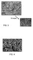
- FIG. 3 is an electron micrograph of ⁇ -type silicon nitride series ceramic.
- ⁇ -type silicon nitride series ceramic is formed of hexagonal system columnar crystals
- the porous ceramic particle 1 a is formed of crystalline lumps which are masses of columnar crystals, in which numerous crystalline lumps are combined to each other. Being formed of such columnar crystals, the porous ceramic body 1 can have a specific surface area equal to or greater than 0.5 m 2 /cc.
- small pores can be formed between the columnar crystals, as well as large pores between crystalline lumps.
- FIG. 4 is an electron micrograph of a porous ceramic body of a ceramic filter in accordance with a comparative example to the present invention.
- the porous ceramic body shown in FIG. 4 is formed of silicon carbide (SiC) ceramic and has a specific surface area smaller than 0.5 m 2 /cc.
- SiC silicon carbide
- FIG. 4 there are only large pores between ceramic particles, lacking minute pores such as that shown in FIG. 3 .
- the coating portion is disposed onto large pores between ceramic particles, and thus it is understood that air ventilation is worsened and the dispersion of the coating portion is reduced.
- the coating portion 2 is formed to have an amount equal to or greater than 15g/l.
- the amount of the coating portion 2 is a weight thereof with respect to an apparent volume of the entire ceramic filter including air passages and pores through which an exhaust gas flows.
- the amount of the coating portion is the weight thereof with respect to the apparent volume including the cells and pores which constitute air passages.
- the dispersion of the catalyst is further improved, thereby hindering agglomeration of the catalyst caused by the use under a high temperature, and prolonging the catalyst performance for a long period of time.
- the increase rate of the pressure loss of the porous ceramic body 1 due to the formation of the coating portion 2 is equal to or less than 20%. This is because the air ventilation characteristic of the ceramic filter would be reduced if the amount of the coating portion 2 is so increased that the increase rate of the pressure loss exceeds 20%.
- the material of the coating portion 2 has metal oxide as a major component, and it is preferable to contain at least one of aluminum oxide, titanium oxide, zirconium oxide, silicon oxide, cerium oxide, and lanthanum oxide.
- the catalyst is supported by these elements.
- a method for manufacturing the ceramic filter shown in FIG. 1 is explained.
- a method for manufacturing the porous ceramic body 1 There are two types of methods to manufacture the porous ceramic body 1: a pressureless sintering in which a source powder material having the same composition as the porous ceramic body 1 is sintered with a sintering aid, and a post reaction sintering in which a source powder material of metallic Si is nitrided with a proper amount of a sintering aid and a pore-forming agent in a first firing step, and then densified by a second firing step.
- a pressureless sintering in which a source powder material having the same composition as the porous ceramic body 1 is sintered with a sintering aid
- a post reaction sintering in which a source powder material of metallic Si is nitrided with a proper amount of a sintering aid and a pore-forming agent in a first firing step, and then densified by a second firing step.
- the porous ceramic body 1 is formed by the following process steps in the pressureless sintering.
- the source powder material is preferably such a powder that grows columnar crystals by sintering, for example, a powder of ⁇ -type silicon nitride, or a mixed powder of ⁇ -type silicon nitride and ⁇ -type silicon nitride.
- the source powder material may also contain, as additional components, silicon carbide powder, boron nitride, and an oxide material such as cerium oxide and zirconium oxide.
- the sintering aid can be a well-known material such as an oxide of a rare earth element (a lanthanoid element including yttrium), and it is preferable to use an oxide of yttrium (Y), ytterbium (Yb), erbium (Er), and the like. MgO, Al 2 O 3 , ZrO 2 , HfO 2 and the like can be used. These sintering aids can be used alone, or in combination of two or more different aids. A compound of rare earth elements or alkaline earth elements (such as a carbonate), which become an oxide during the sintering, can also be used. A small amount of metallic Si can also be added.
- an aluminum compound such as aluminum nitride or aluminum oxide
- Aluminum compounds contribute to strengthening the bonding power between silicon nitride crystalline particles. These aluminum compounds can be added as an oxide or nitride, or as a compound which turns into an oxide or nitride during the sintering.
- a pore-forming agent can be included in the source material. Any conventional pore-forming material which melts or evaporates in the sintering step (3) can be used. That is, as a pore-forming agent makes pores when heated, such a pore-forming agent can form pores either by melting or by evaporating.
- resins such as polyethylene, polypropylene, polymethyl acrylate, polymethyl methacrylate, polyvinyl alcohol, polyphenol, paraffins; plant-based materials such as starch, nuts, walnut shell, and corn; carbon-based materials such as graphite and carbon fiber; and metallic balloons such as iron balloons can be used.
- the pore-forming agent is a resin, it typically melts at a temperature between 100 °C and 500 °C, and a plant-based or carbon-based material is typically oxidized into carbon monoxide or carbon dioxide at about 400 °C, and then evaporates at about 800 °C.
- the ratio of the pore-forming agent is preferably between 10 volume% and 60 volume%. If the pore-forming agent is less than 10 volume%, the amount of pores formed is reduced. If the pore-forming agent exceeds 60 volume%, it became difficult to obtain the pore-forming effect proportional to the amount of the agent used, resulting in unnecessary waste of the agent.
- the sintering may be performed in a non-oxidizing atmosphere by maintaining the temperature at about 1600 ⁇ 1800 °C for a certain period of time (for example, about 1 hour to 3 hours).
- porous ceramic body l is also formed by a post reaction sintering employing process steps similar to process steps (1) ⁇ (4) described above.
- a metallic Si powder is used as a source powder material, which grows columnar crystals at an elevated temperature after it is nitrided.
- the sintering aid and the pore-forming agent are the same as those described in ⁇ Pressureless Sintering> .
- the metallic Si is nitrided by sintering in a nitride atmosphere at 1000-1450 °C, and then densified by sintering at 1700 ⁇ 1800 °C,.
- the coating portion 2 is formed onto the porous ceramic body 1 by wash-coating.
- a method of forming the coating portion 2 is not limited to a specific method, but it can be a method using a slurry, colloid, and solution, which are referred to as a slurry method, colloid method, and solution method, respectively.
- a slurry is made by mixing particles to be a source material for the coating portion 2 into a solvent such as water.
- the main component of the source material of the coating portion 2 is metal oxide, such as aluminum oxide, titanium oxide, zirconium oxide, silicon oxide, cerium oxide, lanthanum oxide, and the like.
- the porous ceramic body 1 is immersed into the slurry, or the slurry is poured onto the porous ceramic body 1. After that, an air blowing process and a heating process at a temperature about 500 °C are performed, whereby the solvent is evaporated so as to form the coating portion 2.
- a colloidal solution is made by mixing particles to be a source material for the coating portion 2 into a solvent such as water, and controlling pH.
- the subsequent processes are the same as that in the slurry method.
- a solution is made by dissolving a source material to form the coating portion 2 by oxidation into a solvent such as water.
- a solvent such as water.
- aluminum nitrate and/or aluminum acetate may be used as the source material.
- the porous ceramic body 1 is immersed into the solution, or the solution is applied onto the porous ceramic body 1.
- an oxidation process is performed by heating at a temperature 600 °C or higher so as to form the coating portion 2.
- the ceramic filer in accordance with one embodiment of the present invention includes the porous ceramic body which is a sintered body of ceramic particles, and the coating portion which is formed on a surface of each of the ceramic particles so as to support a catalyst.
- the porous ceramic body has a specific surface area equal to or greater than 0.5 m 2 /cc measured by a mercury porosimeter, and the amount of the coating portion is equal to or greater than 15g/l.
- the amount of the coating portion is a weight thereof with respect to an apparent volume of the entire ceramic filter including air passages and pores through which an exhaust gas flows.
- the surface area for forming the coating portion per unit volume is increased.
- the coating portion is formed on that large specific surface area by the amount equal to or greater than 15g/l.
- the catalyst is dispersedly supported by the coating portion which is thus formed on a large area per unit volume.
- pores having a pore diameter equal to or smaller than 10 ⁇ m are equal to or greater than 10% of the entire pores.
- the small pores having the pore diameter equal to or smaller than 10 ⁇ m generally have small contribution to the ventilation characteristic of the exhaust gas.
- the coating portion easily fills the small pores well, since the source powder material thereof is typically made in a form of liquid such as slurry, colloid, or solution and applied to the surface of each of the ceramic particles. Accordingly, although the coating portion is formed with such an amount of equal to or greater than 15g/l, it is disposed onto the small pores having a small contribution to the ventilation characteristic, and thus it is possible to prevent the pressure loss increase due to the clogging of the large pores having the pore diameter equal to or greater than 10 ⁇ m.
- an increase rate of the pressure loss after forming the coating portion is equal to or less than 20 % , compared with the pressure loss before the formation of the coating portion. According to this structure, decrease in the ventilation characteristic is suppressed.
- pores having a pore diameter equal to or smaller than 10 ⁇ m are equal to or smaller than 50% of the entire pores. According to this structure, decrease in the strength of the ceramic filter is suppressed.
- the coating portion has a metal oxide as a main component, and for example, includes at least one element selected from the group consisting of aluminum oxide, titanium oxide, zirconium oxide, silicon oxide, cerium oxide, and lanthanum oxide.
- the porous ceramic body includes, as the ceramic particles, a number of crystalline lumps formed of columnar crystals, where the crystalline lumps are coupled to each other.
- the porous ceramic body is made of a silicon nitride series ceramic, for example.
- the source material is prepared with 48 weight% of metallic silicon (Si), 1.3 weight% of zirconium dioxide (ZrO 2 ), 1.3 weight% of alumina-magnesia-spinel (MgAl 2 O 4 ), 25 weight% of ⁇ -type silicon nitride ( ⁇ -Si 3 N 4 ), 13 weight% of a pore-forming agent, and 11.4 weight% of other binders, and the porous ceramic body 1 is manufactured by the following process steps.
- the metallic silicon having a particle diameter of about 50 ⁇ 100 ⁇ m and the ⁇ -type silicon nitride having a particle diameter of about 100 ⁇ m are used.
- aluminum nitrate which is a source material to form the coating portion 2 is dissolved into water and then applied onto the porous ceramic body 1. Then, a heating process is performed at a temperature 600 °C so as to form the coating portion 2.
- the amount of the coating portion 2 is 15 g/l in Embodiment 1, 20 g/l in Embodiment 2, 40 g/l in Embodiment 3, and 60 g/l in Embodiment 4.
- platinum (Pt) particles which are the catalyst are disposed so as to be supported by the coating portion 2. More specifically, Pt dinitrodiammine nitric acid solution containing a desired amount of platinum is impregnated into the coating portion 2 to be supported, a drying process is performed at 120 °C, and then a firing process is performed in the air at 500 °C for an hour, whereby Pt particles having a particle diameter of 1 ⁇ 5 nm are dispersedly supported on the surface of the coating portion 2.
- the ceramic filter in accordance with Embodiment 5 is manufactured in the same manner as that of Embodiment 3 except that the source material contains 7 weight% of the pore-forming agent and the second firing temperature is 1600 °C.
- the ceramic filter in accordance with Embodiment 6 is manufactured in the same manner as that of Embodiment 3 except that the metallic silicon has a minute particle diameter equal to or less than 50 ⁇ m, the ⁇ -type silicon nitride ceramic has a particle diameter equal to or less than 550 ⁇ m, and the source material contains 20 weight% of the pore-forming agent.
- the ceramic filter in accordance with Embodiment 7 is manufactured in the same manner as that of Embodiment 3 except that titanium isopropoxide dissolved into isopropyl alcohol, instead of aluminum nitrate dissolved into water, is used as the source material for the coating portion 2.
- the source material is prepared with 70 weight% of silicon carbide (SiC) powder, 10 weight% of a binder, and 20 weight% of water, and a porous ceramic body 10 is manufactured by the following process steps.
- SiC silicon carbide
- aluminum nitrate which is a source material for the coating portion 20 is dissolved into water and then applied onto the porous ceramic body 10.
- the amount of the coating portion 20 is 20 g/l in Comparative Example 1, 40 g/l in Comparative Example 2, and 60 g/l in Comparative Example 3.
- platinum (Pt) particles which are the catalyst are disposed so as to be supported by the coating portion 20.
- Table 1 shows evaluation results for Embodiments 1 ⁇ 7 and Comparative Examples 1 ⁇ 3 with respect to a specific surface area, a porosity ratio which is a volume ratio of the pores having a pore diameter equal to or less than 10 ⁇ m with respect to the entire pores, a coating amount, an amount of Pt, an increase rate of the pressure loss, and the dispersion of Pt.
- the specific surface area of the porous ceramic body before forming the coating portion is 0.5 m 2 /cc in Embodiment 5, 2.3 m 2 /cc in Embodiments 1 ⁇ 4 and 7, 2.5 m 2 /cc in Embodiment 6, and 0.2 m 2 /cc in the Comparative Examples, as shown in Table 1.
- the pore diameter distribution was measured using a mercury intrusion technique for the porous ceramic body before forming the coating portion.
- FIG. 5 is a diagram showing measurement results of the pore diameter distribution for the porous ceramic body 1 in Embodiments 1 ⁇ 4 and 7.
- FIG. 6 is a diagram showing measurement results of the pore diameter distribution for the porous ceramic body 10 in the Comparative Examples 1 ⁇ 3.
- Comparative Examples 1 ⁇ 3 and Embodiments 1 ⁇ 4 and 7 have a peak at the pore diameter greater than 10 ⁇ m. This peak is attributed to the large pores between the ceramic particles.
- Comparative Examples 1 ⁇ 3 have little or no pores having the pore diameter equal to or less than 10 ⁇ m
- Embodiments 1 ⁇ 4 and 7 shows existence of small pores having the pore diameter equal to or less than 10 ⁇ m.
- the ceramic particles are in a form of crystalline lumps which are masses of columnar crystals, providing numerous minute pores formed between the columnar crystals.
- the ratio of the pores having the pore diameter equal to or smaller than 10 ⁇ m is equal to or greater than 10 volume% with respect to the entire pores. More specifically, in Embodiments 1 ⁇ 4, 6, and 7, the ratio is equal to or greater than 30 volume%, demonstrating that the Embodiments have the higher ratio of the pores having the pore diameter equal to or smaller than 10 ⁇ m, compared with Comparative Examples 1 -3.
- the porosity with respect to the entire volume is 64.6% in Embodiments 1 ⁇ 4, and 48.0% in Comparative Examples 1-3. This is because the Embodiments presumably have more pores due to the additional minute pores.
- the coating portion By forming the coating portion on such a porous ceramic body, in the Embodiments, the coating portion fills the minute pores between the columnar crystals as shown in FIG. 1 , so as to prevent the pressure loss from increasing. However, in the Comparative Examples, the pressure loss is tend to be increased since the coating portion is formed so as to block the large pores between the ceramic particles, as shown in FIG. 2 .
- the pore diameter distribution is also measured for the porous ceramic body provided with the coating portion using the mercury intrusion technique. It is confirmed that the amount of pores having the pore diameter equal to or greater than 10 ⁇ m is significantly reduced in the Comparative Examples, while the amount of pores mainly having the pore diameter equal to or smaller than 10 ⁇ m is significantly reduced in the Embodiments. Also, in some cases, the amount of pores having the pore diameter equal to or smaller than 10 ⁇ m is increased by forming the coating portion. This is because ⁇ -alumina particles constituting the coating portion have a large specific surface area and minute pores.
- FIG. 7A is an electron micrograph of Embodiment 2
- FIG. 7B is an EDX map for element Al in Embodiment 2
- FIG. 7C is an electron micrograph of Embodiment 4
- FIG. 7D is an EDX map for element Al in Embodiment 4
- FIG. 7E is an electron micrograph of Comparative Example 1
- FIG. 7F is an EDX map for element Al in Comparative Example 1.
- the Embodiments have a higher dispersibility of element Al. This means that the coating portion has a higher dispersibility in the Embodiments. This is because the Embodiments have a larger specific surface area and a large number of minute pores having the pore diameter equal to or less than 10 ⁇ m are dispersed such that the coating portion filling the minute pores is uniformly dispersed.
- the coating portion has a high dispersibility
- the catalyst supported by the coating portion also has a high dispersibility
- the pressure loss is measured by an experimenting device as shown in FIG. 8 . That is, a honeycomb filter F is formed into a honeycomb test sample 3 having 35 x 35 x 150 mm dimensions, 260 cpsi cell density, and 10 mil wall thickness, and is disposed in a ventilation passage 4, and a pressure loss (kPa) which is a pressure difference between before and after the honeycomb filter F is measured using a differential pressure gage 5 by flowing air through the ventilation passage 4.
- the increase rate of the pressure loss due to forming the coating portion is calculated by measuring the pressure loss for both of the honeycomb filter before forming the coating portion and the honeycomb filter after forming the coating portion.
- the present invention can be used for a filter to capture solid particles in an exhaust gas from an internal combustion engine and the like.
Landscapes
- Chemical & Material Sciences (AREA)
- Engineering & Computer Science (AREA)
- Chemical Kinetics & Catalysis (AREA)
- Organic Chemistry (AREA)
- Materials Engineering (AREA)
- Geometry (AREA)
- Physics & Mathematics (AREA)
- Ceramic Engineering (AREA)
- General Engineering & Computer Science (AREA)
- Mechanical Engineering (AREA)
- Combustion & Propulsion (AREA)
- Health & Medical Sciences (AREA)
- Toxicology (AREA)
- Structural Engineering (AREA)
- Manufacturing & Machinery (AREA)
- Catalysts (AREA)
- Filtering Materials (AREA)
- Processes For Solid Components From Exhaust (AREA)
Abstract
Description
- The present invention relates to a ceramic filter for capturing solid fine particles contained in an exhaust gas from an internal combustion engine and the like.
- Conventionally, a honeycomb filter having a large number of cells extending in a given direction is used as a filter for capturing solid fine particles contained in an exhaust gas from an internal combustion engine. A surface of such a honeycomb filter is coated with a coating material such as alumina by wash-coating in order to support a catalyst, such as platinum (Pt), which oxidatively decomposes the captured solid fine particles, carbon monoxide (CO), and the like.
- On the other hand,
Patent Document 1 andPatent Document 2 disclose methods for forming a layer for carrying a catalyst without using wash-coating. More specifically, -
Patent Document 1 describes a technology in which an oxide film of silicide is formed by heating at 1000 °C to 1500 °C, and then the silicide oxide film surface is coated with a metal compound containing aluminum.Patent Document 2 describes a technology in which an alumina thin film is formed on a surface of each particle constituting a ceramic support by coating the surface with a metal compound containing aluminum and conducting a heating process, where the ceramic support contains tetravalent metal acid insoluble salts, such as zirconium phosphate. -
- Patent Document 1: Japanese Patent No.
4642955 (issued on March 2, 2011 - Patent Document 2: Japanese Patent No.
4498579 (issued on July 7, 2010 - A catalyst such as platinum used under a high temperature is subject to gradual sintering (agglomeration) which degrades the catalyst function. In order to solve this problem, a coating amount of a coating material for wash-coating may be increased while reducing a deposition ratio of the catalyst, so as to increase the dispersion of the coating material. However, in the conventional ceramic using wash coating, if the amount of coating material is increased, it will block pores of the ceramic so as to increase a pressure loss. This prevents the coating amount from being increased and thus the dispersibility of the catalyst cannot be increased.
- Although
Patent Documents - In the light of the forgoing, the present invention is to realize a ceramic filter that can increase the dispersion of the catalyst.
- In order to solve the above-mentioned problems, a ceramic filter in accordance with the present invention includes a porous ceramic body which is a sintered body of ceramic particles and a coating portion formed on a surface of each of the ceramic particles to support a catalyst, wherein the porous ceramic body has a specific surface area equal to or greater than 0.5 m2/cc measured by a mercury porosimeter, and an amount of the coating portion is equal to or greater than 15g/l.
- In accordance with the present invention, the dispersion of the catalyst is advantageously increased.
-
-
FIG. 1 is a schematic diagram showing a ceramic filter in accordance with one embodiment of the present invention. -
FIG. 2 is a schematic diagram showing a ceramic filter as a comparative example. -
FIG. 3 is an electron micrograph of a porous ceramic body of the ceramic filter in accordance with one embodiment of the present invention. -
FIG. 4 is an electron micrograph of a porous ceramic body of the ceramic filter in the comparative example. -
FIG. 5 is a diagram showing a measurement result of a pore diameter distribution for the porous ceramic body in the embodiments of the present invention. -
FIG. 6 is a diagram showing a measurement result of a pore diameter distribution in the porous ceramic body in the comparative examples. -
FIGS. 7A- 7F are electron micrographs or EDX maps of the embodiment of the present invention or the comparative example:FIG. 7A is an electron micrograph ofEmbodiment 2;FIG. 7B is an EDX map for element Al inEmbodiment 2;FIG. 7C is an electron micrograph ofEmbodiment 4;FIG. 7D is an EDX map for element Al inEmbodiment 4;FIG. 7E is an electron micrograph of Comparative Example 1; andFIG. 7F is an EDX map for element Al in Comparative Example 1. -
FIG. 8 is a schematic diagram showing a testing apparatus for measuring changes in a pressure loss. - Embodiments of the present invention will be explained in detail below.
FIG. 1 is a schematic diagram showing a ceramic filter in accordance with one embodiment of the present invention. As shown inFIG. 1 , the ceramic filter includes a porousceramic body 1 which is a sintered body ofceramic particles 1a, and acoating portion 2 formed on a surface of each of theceramic particles 1a to support a catalyst. - The porous
ceramic body 1 has a specific surface area equal to or greater than 0.5 m2/cc measured by a mercury porosimeter. Since the specific surface area is equal to or greater than 0.5 m2/cc, an area for forming thecoating portion 2 per unit area is increased. The catalyst is dispersedly supported by thecoating portion 2 which is formed on a larger area per unit area. As a result, the degree of dispersion of the catalyst can be increased. -
FIG. 2 is a schematic diagram showing a ceramic filter in accordance with a comparative example. As shown inFIG. 2 , the ceramic filter of the comparative example has a porousceramic body 10 which is a sintered body ofceramic particles 10a, and acoating portion 20 formed between theceramic particles 10a to support a catalyst. The specific surface area of the porousceramic body 10 is about 0.2 m2/cc, and most of the pores are large pores disposed between theceramic particles 10a and have a relatively large pore diameter. Accordingly, thecoating portion 20 is formed in such a manner that blocks the pores, thereby elevating the increase rate of the pressure loss due to the formation of thecoating portion 20. In addition, since thecoating portion 20 is mostly disposed onto the large pores and thus tends to agglomerate, the dispersion of the catalyst supported by thecoating portion 20 is also reduced, degrading the catalytic performance. - On the other hand, the ceramic filter in accordance with an embodiment of the present invention includes a porous
ceramic body 1 that has a specific surface area equal to or greater than 0.5 m2/cc, as shown inFIG. 1 . Because of this, the surface area of thecoating portion 2 per unit volume can be increased so as to maintain a high degree of dispersion of the catalyst, improving the catalytic performance. - In addition, as will be described below, when the porous
ceramic body 1 is formed of columnar crystals, as shown inFIG. 1 , the porousceramic body 1 includes numerous minute pores in addition to the large pores formed betweenceramic particles 1a which have a relatively large pore diameter. - Accordingly, the
coating portion 2 for supporting the catalyst is formed dispersedly over the surface of the ceramic particle by filing the minute pores. As a result, the catalyst supported by thecoating portion 2 is also dispersed, thereby increasing the surface area of the catalyst as a whole and improving the catalytic performance. - In addition, the
coating portion 2 is tend to fill the minute pores and thus less likely to block the large pores. Because of this, the increase rate of the pressure loss due to the formation of thecoating portion 2 can be suppressed to a low level. Thus, an amount of thecoating portion 2 can be increased so as to further improve the dispersion of the catalyst supported by thecoating portion 2. - It is preferable that, in the porous
ceramic body 1, the pores having a pore diameter equal to or smaller than 10µm are equal to or greater than 10% of the entire pores. By this, thecoating portion 2 can be placed to small pores with the diameter equal to or smaller than 10 µm, so as to further prevent the increase of the pressure loss due to clogging of the large pores. - It is preferable that, in the porous
ceramic body 1, the pores having a pore diameter equal to or smaller than 10µm are equal to or smaller than 50% of the entire pores. If the pores having the diameter equal to or less than 10 µm exceed 50% of the entire pores, the strength of the ceramic filter is reduced. - A preferable material for the porous
ceramic body 1 is β-type silicon nitride (Si3N4) series ceramic. Silicon nitride series ceramic is in a form of a polycrystalline body which is mostly composed of silicon nitride, and it may contain a sintering aid such as Y2O3 or MgO. Silicon nitride series ceramic also includes sialon in which part of silicon and part of nitride in silicon nitride have been replaced by aluminum and oxygen, respectively. -
FIG. 3 is an electron micrograph of β-type silicon nitride series ceramic. As shown inFIG. 3 , β-type silicon nitride series ceramic is formed of hexagonal system columnar crystals, and the porousceramic particle 1 a is formed of crystalline lumps which are masses of columnar crystals, in which numerous crystalline lumps are combined to each other. Being formed of such columnar crystals, the porousceramic body 1 can have a specific surface area equal to or greater than 0.5 m2/cc. In addition, small pores can be formed between the columnar crystals, as well as large pores between crystalline lumps. - On the other hand,
FIG. 4 is an electron micrograph of a porous ceramic body of a ceramic filter in accordance with a comparative example to the present invention. The porous ceramic body shown inFIG. 4 is formed of silicon carbide (SiC) ceramic and has a specific surface area smaller than 0.5 m2/cc. As shown inFIG. 4 , there are only large pores between ceramic particles, lacking minute pores such as that shown inFIG. 3 . As a result, the coating portion is disposed onto large pores between ceramic particles, and thus it is understood that air ventilation is worsened and the dispersion of the coating portion is reduced. - The
coating portion 2 is formed to have an amount equal to or greater than 15g/l. The amount of thecoating portion 2 is a weight thereof with respect to an apparent volume of the entire ceramic filter including air passages and pores through which an exhaust gas flows. For example, in a honeycomb type ceramic filter, which has a number of cells extending in an axis direction and arranged to from a lattice in a cross-section perpendicular to the axis direction at both ends, where the lattice includes alternately arranged open ends and closed ends of the cells, the amount of the coating portion is the weight thereof with respect to the apparent volume including the cells and pores which constitute air passages. By providing the amount of the coating portion equal to or greater than 15g/l, the dispersion of the catalyst is further improved, thereby hindering agglomeration of the catalyst caused by the use under a high temperature, and prolonging the catalyst performance for a long period of time. - However, it is preferable that the increase rate of the pressure loss of the porous
ceramic body 1 due to the formation of thecoating portion 2 is equal to or less than 20%. This is because the air ventilation characteristic of the ceramic filter would be reduced if the amount of thecoating portion 2 is so increased that the increase rate of the pressure loss exceeds 20%. - The material of the
coating portion 2 has metal oxide as a major component, and it is preferable to contain at least one of aluminum oxide, titanium oxide, zirconium oxide, silicon oxide, cerium oxide, and lanthanum oxide. The catalyst is supported by these elements. - Next, a method for manufacturing the ceramic filter shown in
FIG. 1 is explained. First, a method for manufacturing the porousceramic body 1 is explained. There are two types of methods to manufacture the porous ceramic body 1: a pressureless sintering in which a source powder material having the same composition as the porousceramic body 1 is sintered with a sintering aid, and a post reaction sintering in which a source powder material of metallic Si is nitrided with a proper amount of a sintering aid and a pore-forming agent in a first firing step, and then densified by a second firing step. - The porous
ceramic body 1 is formed by the following process steps in the pressureless sintering. - (1) Source materials including the source powder material and the sintering aid are measured and mixed.
- (2) The mixed material is formed into a predetermined shape (for example, a honeycomb-shaped cylinder having φ144 mm x 150 mm) by extrusion molding. Here, the honeycomb-shaped cylinder means a honeycomb body in which a number of cells extending in a predetermined direction are arranged next to one another via cell-dividing walls, where each of the cells are penetrating in the predetermined direction.
- (3) The molded body formed in step (2) is sintered.
- (4) Additional processing steps such as polishing and agglutination are performed.
- In process step (1), the source powder material is preferably such a powder that grows columnar crystals by sintering, for example, a powder of α-type silicon nitride, or a mixed powder of α-type silicon nitride and β-type silicon nitride. The source powder material may also contain, as additional components, silicon carbide powder, boron nitride, and an oxide material such as cerium oxide and zirconium oxide.
- The sintering aid can be a well-known material such as an oxide of a rare earth element (a lanthanoid element including yttrium), and it is preferable to use an oxide of yttrium (Y), ytterbium (Yb), erbium (Er), and the like. MgO, Al2O3, ZrO2, HfO2 and the like can be used. These sintering aids can be used alone, or in combination of two or more different aids. A compound of rare earth elements or alkaline earth elements (such as a carbonate), which become an oxide during the sintering, can also be used. A small amount of metallic Si can also be added.
- In addition to the above-mentioned sintering aids, it is also effective to add the following materials as a part of the sintering aid: an aluminum compound such as aluminum nitride or aluminum oxide; and oxide or nitride of titanium, zirconium, or hafnium, and the like. Aluminum compounds contribute to strengthening the bonding power between silicon nitride crystalline particles. These aluminum compounds can be added as an oxide or nitride, or as a compound which turns into an oxide or nitride during the sintering.
- A pore-forming agent can be included in the source material. Any conventional pore-forming material which melts or evaporates in the sintering step (3) can be used. That is, as a pore-forming agent makes pores when heated, such a pore-forming agent can form pores either by melting or by evaporating.
- For example, resins such as polyethylene, polypropylene, polymethyl acrylate, polymethyl methacrylate, polyvinyl alcohol, polyphenol, paraffins; plant-based materials such as starch, nuts, walnut shell, and corn; carbon-based materials such as graphite and carbon fiber; and metallic balloons such as iron balloons can be used. When the pore-forming agent is a resin, it typically melts at a temperature between 100 °C and 500 °C, and a plant-based or carbon-based material is typically oxidized into carbon monoxide or carbon dioxide at about 400 °C, and then evaporates at about 800 °C.
- The ratio of the pore-forming agent is preferably between 10 volume% and 60 volume%. If the pore-forming agent is less than 10 volume%, the amount of pores formed is reduced. If the pore-forming agent exceeds 60 volume%, it became difficult to obtain the pore-forming effect proportional to the amount of the agent used, resulting in unnecessary waste of the agent.
- In the process step (3), the sintering may be performed in a non-oxidizing atmosphere by maintaining the temperature at about 1600∼1800 °C for a certain period of time (for example, about 1 hour to 3 hours).
- On the other hand, the porous ceramic body lis also formed by a post reaction sintering employing process steps similar to process steps (1) ∼ (4) described above.
- However, in process step (1), a metallic Si powder is used as a source powder material, which grows columnar crystals at an elevated temperature after it is nitrided. The sintering aid and the pore-forming agent are the same as those described in <Pressureless Sintering> .
- In process step (3), after a degreasing process, the metallic Si is nitrided by sintering in a nitride atmosphere at 1000-1450 °C, and then densified by sintering at 1700∼1800 °C,.
- Large pores are provided between the
ceramic particles 1a using either of the above-described methods. The large pores become larger in the presence of the pore-forming agent, enhancing the air ventilation. Using a source powder material that grows columnar crystals, minute pores are formed between the columnar crystals on a surface of theceramic particle 1a. By this, it is possible to manufacture the porousceramic body 1 having a specific surface area equal to or greater than 0.5 m2/cc. - Next, the
coating portion 2 is formed onto the porousceramic body 1 by wash-coating. A method of forming thecoating portion 2 is not limited to a specific method, but it can be a method using a slurry, colloid, and solution, which are referred to as a slurry method, colloid method, and solution method, respectively. - A slurry is made by mixing particles to be a source material for the
coating portion 2 into a solvent such as water. The main component of the source material of thecoating portion 2 is metal oxide, such as aluminum oxide, titanium oxide, zirconium oxide, silicon oxide, cerium oxide, lanthanum oxide, and the like. The porousceramic body 1 is immersed into the slurry, or the slurry is poured onto the porousceramic body 1. After that, an air blowing process and a heating process at a temperature about 500 °C are performed, whereby the solvent is evaporated so as to form thecoating portion 2. - A colloidal solution is made by mixing particles to be a source material for the
coating portion 2 into a solvent such as water, and controlling pH. The subsequent processes are the same as that in the slurry method. - A solution is made by dissolving a source material to form the
coating portion 2 by oxidation into a solvent such as water. For example, when thecoating portion 2 of aluminum oxide is to be formed, aluminum nitrate and/or aluminum acetate may be used as the source material. Then, the porousceramic body 1 is immersed into the solution, or the solution is applied onto the porousceramic body 1. After that, an oxidation process is performed by heating at a temperature 600 °C or higher so as to form thecoating portion 2. - As described above, the ceramic filer in accordance with one embodiment of the present invention includes the porous ceramic body which is a sintered body of ceramic particles, and the coating portion which is formed on a surface of each of the ceramic particles so as to support a catalyst. The porous ceramic body has a specific surface area equal to or greater than 0.5 m2/cc measured by a mercury porosimeter, and the amount of the coating portion is equal to or greater than 15g/l. Here, the amount of the coating portion is a weight thereof with respect to an apparent volume of the entire ceramic filter including air passages and pores through which an exhaust gas flows.
- In accordance with the structure mentioned above, due to the specific surface area equal to or greater than 0.5 m2/cc, the surface area for forming the coating portion per unit volume is increased. And the coating portion is formed on that large specific surface area by the amount equal to or greater than 15g/l. The catalyst is dispersedly supported by the coating portion which is thus formed on a large area per unit volume. As a result, the dispersion of the catalyst can be improved, and whereby the agglomeration of the catalyst is suppressed even under the use at a high temperature, so as to maintain the catalyst performance for a long period of time.
- In addition, in the ceramic filter of the present invention, it is preferable that in the porous ceramic body, pores having a pore diameter equal to or smaller than 10µm are equal to or greater than 10% of the entire pores.
- In accordance with this structure, the small pores having the pore diameter equal to or smaller than 10µm generally have small contribution to the ventilation characteristic of the exhaust gas. On the other hand, the coating portion easily fills the small pores well, since the source powder material thereof is typically made in a form of liquid such as slurry, colloid, or solution and applied to the surface of each of the ceramic particles. Accordingly, although the coating portion is formed with such an amount of equal to or greater than 15g/l, it is disposed onto the small pores having a small contribution to the ventilation characteristic, and thus it is possible to prevent the pressure loss increase due to the clogging of the large pores having the pore diameter equal to or greater than 10µm.
- Furthermore, in the ceramic filter of the present invention, it is preferable that an increase rate of the pressure loss after forming the coating portion is equal to or less than 20 % , compared with the pressure loss before the formation of the coating portion. According to this structure, decrease in the ventilation characteristic is suppressed.
- In addition, in the ceramic filter of the present invention, it is preferable that in the porous ceramic body, pores having a pore diameter equal to or smaller than 10µm are equal to or smaller than 50% of the entire pores. According to this structure, decrease in the strength of the ceramic filter is suppressed.
- The coating portion has a metal oxide as a main component, and for example, includes at least one element selected from the group consisting of aluminum oxide, titanium oxide, zirconium oxide, silicon oxide, cerium oxide, and lanthanum oxide.
- The porous ceramic body includes, as the ceramic particles, a number of crystalline lumps formed of columnar crystals, where the crystalline lumps are coupled to each other. The porous ceramic body is made of a silicon nitride series ceramic, for example.
- The present invention is not limited to the embodiments described above, but various modifications may be employed within the scope of the claims. That is, the technical scope of the present invention encompasses embodiments that are obtained by combining technical means that are modified within the scope of the claims.
- The source material is prepared with 48 weight% of metallic silicon (Si), 1.3 weight% of zirconium dioxide (ZrO2), 1.3 weight% of alumina-magnesia-spinel (MgAl2O4), 25 weight% of β-type silicon nitride (β-Si3N4), 13 weight% of a pore-forming agent, and 11.4 weight% of other binders, and the porous
ceramic body 1 is manufactured by the following process steps. The metallic silicon having a particle diameter of about 50∼100µm and the β-type silicon nitride having a particle diameter of about 100µm are used. - 1. The above-mentioned source materials are mixed and kneaded.
- 2. A honeycomb-shaped cylinder body is formed using an extruder.
- 3. After a degreasing process, a reaction sintering is performed. The firing temperature is 1400 °C for the first firing, and 1700 °C for the second firing.
- 4. Additional processing such as polishing and agglutination are performed.
- After that, aluminum nitrate which is a source material to form the
coating portion 2 is dissolved into water and then applied onto the porousceramic body 1. Then, a heating process is performed at a temperature 600 °C so as to form thecoating portion 2. The amount of thecoating portion 2 is 15 g/l inEmbodiment 1, 20 g/l inEmbodiment 2, 40 g/l in Embodiment 3, and 60 g/l inEmbodiment 4. - Then, as the final step, platinum (Pt) particles which are the catalyst are disposed so as to be supported by the
coating portion 2. More specifically, Pt dinitrodiammine nitric acid solution containing a desired amount of platinum is impregnated into thecoating portion 2 to be supported, a drying process is performed at 120 °C, and then a firing process is performed in the air at 500 °C for an hour, whereby Pt particles having a particle diameter of 1∼5 nm are dispersedly supported on the surface of thecoating portion 2. - The ceramic filter in accordance with
Embodiment 5 is manufactured in the same manner as that of Embodiment 3 except that the source material contains 7 weight% of the pore-forming agent and the second firing temperature is 1600 °C. - The ceramic filter in accordance with Embodiment 6 is manufactured in the same manner as that of Embodiment 3 except that the metallic silicon has a minute particle diameter equal to or less than 50 µm, the β-type silicon nitride ceramic has a particle diameter equal to or less than 550 µm, and the source material contains 20 weight% of the pore-forming agent.
- The ceramic filter in accordance with Embodiment 7 is manufactured in the same manner as that of Embodiment 3 except that titanium isopropoxide dissolved into isopropyl alcohol, instead of aluminum nitrate dissolved into water, is used as the source material for the
coating portion 2. - The source material is prepared with 70 weight% of silicon carbide (SiC) powder, 10 weight% of a binder, and 20 weight% of water, and a porous
ceramic body 10 is manufactured by the following process steps. - 1. The above-mentioned source materials are mixed and kneaded.
- 2. A honeycomb-shaped cylinder body is formed using an extruder.
- 3. After a degreasing process, a sintering is performed at 2200 °C.
- 4. Additional processing such as polishing and agglutination are performed.
- After that, aluminum nitrate which is a source material for the
coating portion 20 is dissolved into water and then applied onto the porousceramic body 10. The amount of thecoating portion 20 is 20 g/l in Comparative Example 1, 40 g/l in Comparative Example 2, and 60 g/l in Comparative Example 3. - Then, as the final step, platinum (Pt) particles which are the catalyst are disposed so as to be supported by the
coating portion 20. - Table 1 shows evaluation results for
Embodiments 1∼7 and Comparative Examples 1∼3 with respect to a specific surface area, a porosity ratio which is a volume ratio of the pores having a pore diameter equal to or less than 10 µm with respect to the entire pores, a coating amount, an amount of Pt, an increase rate of the pressure loss, and the dispersion of Pt.Table 1 No. Source Material Specific Surface Area m2/cc Porosity Ratio of Pores equal to or less than 10 µm % Coating Material Coating Amount g/L Amount of Pt Increase Rate of Pressure Loss % Example 1 Silicon Nitride 2.3 30 Aluminum Oxide 15 0.40% 0.1 Example 2 Silicon Nitride 2.3 30 Aluminum Oxide 20 0.40% 0.5 Example 3 Silicon Nitride 2.3 30 Aluminum Oxide 40 0.40% 0.1 Example 4 Silicon Nitride 2.3 30 Aluminum Oxide 60 0.40% 3.6 Example 5 Silicon Nitride 0.5 10 Aluminum Oxide 40 0.40% 5.2 Example 6 Silicon Nitride 2.5 50 Aluminum Oxide 40 0.40% 0.1 Example 7 Silicon Nitride 2.3 30 Titanium Oxide 40 0.40% 0.2 Comparative Example 1 Silicon Carbide 0.2 10 Aluminum Oxide 20 0.40% 2.0 Comparative Example 2 Silicon Carbide 0.2 10 Aluminum Oxide 40 0.40% 9.3 Comparative Example 3 Silicon Carbide 0.2 10 Aluminum Oxide 60 0.40% 16.3 - The specific surface area of the porous ceramic body before forming the coating portion, measured by a mercury porosimeter, is 0.5 m2/cc in
Embodiment 5, 2.3 m2/cc inEmbodiments 1∼4 and 7, 2.5 m2/cc in Embodiment 6, and 0.2 m2/cc in the Comparative Examples, as shown in Table 1. - The pore diameter distribution was measured using a mercury intrusion technique for the porous ceramic body before forming the coating portion.
-
FIG. 5 is a diagram showing measurement results of the pore diameter distribution for the porousceramic body 1 inEmbodiments 1∼4 and 7.FIG. 6 is a diagram showing measurement results of the pore diameter distribution for the porousceramic body 10 in the Comparative Examples 1∼3. - As shown in
FIGS. 5 and 6 , all of Comparative Examples 1∼3 andEmbodiments 1∼4 and 7 have a peak at the pore diameter greater than 10 µm. This peak is attributed to the large pores between the ceramic particles. - On the other hand, while Comparative Examples 1∼3 have little or no pores having the pore diameter equal to or less than 10µm,
Embodiments 1∼4 and 7 shows existence of small pores having the pore diameter equal to or less than 10µm. Thus is because in the Embodiments, the ceramic particles are in a form of crystalline lumps which are masses of columnar crystals, providing numerous minute pores formed between the columnar crystals. - As shown in Table 1, in the Embodiments, the ratio of the pores having the pore diameter equal to or smaller than 10µm is equal to or greater than 10 volume% with respect to the entire pores. More specifically, in
Embodiments 1∼4, 6, and 7, the ratio is equal to or greater than 30 volume%, demonstrating that the Embodiments have the higher ratio of the pores having the pore diameter equal to or smaller than 10µm, compared with Comparative Examples 1 -3. The porosity with respect to the entire volume is 64.6% inEmbodiments 1∼4, and 48.0% in Comparative Examples 1-3. This is because the Embodiments presumably have more pores due to the additional minute pores. - By forming the coating portion on such a porous ceramic body, in the Embodiments, the coating portion fills the minute pores between the columnar crystals as shown in
FIG. 1 , so as to prevent the pressure loss from increasing. However, in the Comparative Examples, the pressure loss is tend to be increased since the coating portion is formed so as to block the large pores between the ceramic particles, as shown inFIG. 2 . - The pore diameter distribution is also measured for the porous ceramic body provided with the coating portion using the mercury intrusion technique. It is confirmed that the amount of pores having the pore diameter equal to or greater than 10 µm is significantly reduced in the Comparative Examples, while the amount of pores mainly having the pore diameter equal to or smaller than 10 µm is significantly reduced in the Embodiments. Also, in some cases, the amount of pores having the pore diameter equal to or smaller than 10 µm is increased by forming the coating portion. This is because γ-alumina particles constituting the coating portion have a large specific surface area and minute pores.
- The mapping of element Al forming the coating portion is examined for
Embodiments FIG. 7A is an electron micrograph ofEmbodiment 2,FIG. 7B is an EDX map for element Al inEmbodiment 2,FIG. 7C is an electron micrograph ofEmbodiment 4,FIG. 7D is an EDX map for element Al inEmbodiment 4,FIG. 7E is an electron micrograph of Comparative Example 1, andFIG. 7F is an EDX map for element Al in Comparative Example 1. - As shown in
FIG. 7 , it is confirmed that, compared with the Comparative Examples, the Embodiments have a higher dispersibility of element Al. This means that the coating portion has a higher dispersibility in the Embodiments. This is because the Embodiments have a larger specific surface area and a large number of minute pores having the pore diameter equal to or less than 10 µm are dispersed such that the coating portion filling the minute pores is uniformly dispersed. - As such, since the coating portion has a high dispersibility, the catalyst supported by the coating portion also has a high dispersibility.
- The pressure loss is measured by an experimenting device as shown in
FIG. 8 . That is, a honeycomb filter F is formed into a honeycomb test sample 3 having 35 x 35 x 150 mm dimensions, 260 cpsi cell density, and 10 mil wall thickness, and is disposed in aventilation passage 4, and a pressure loss (kPa) which is a pressure difference between before and after the honeycomb filter F is measured using adifferential pressure gage 5 by flowing air through theventilation passage 4. The increase rate of the pressure loss due to forming the coating portion is calculated by measuring the pressure loss for both of the honeycomb filter before forming the coating portion and the honeycomb filter after forming the coating portion. - As shown in Table 1, it is confirmed that the increase rate of the pressure loss is suppressed at a low level in accordance with the Embodiments. If the increase rate of the pressure loss is to be suppressed within 20%, about 70g/l of coating portion can be formed according to the Embodiments.
- The present invention can be used for a filter to capture solid particles in an exhaust gas from an internal combustion engine and the like.
-
- 1:
- porous ceramic body
- 1a:
- ceramic particle
- 2:
- coating portion
Claims (7)
- A ceramic filter comprising:a porous ceramic body which is a sintered body of ceramic particles; anda coating portion formed on a surface of each of the ceramic particles to support a catalyst,wherein the porous ceramic body has a specific surface area equal to or greater than 0.5 m2/cc, measured by a mercury porosimeter, and an amount of the coating portion is equal to or greater than 15g/l.
- The ceramic filter of claim 1, wherein in the porous ceramic body, pores having a pore diameter equal to or smaller than 10µm are equal to or greater than 10% of entire pores.
- The ceramic filter of claim 1 or 2, wherein an increase rate of a pressure loss after forming the coating portion is equal to or less than 20 % compared with the pressure loss before the formation of the coating portion.
- The ceramic filter of any one of claims 1-3, wherein in the porous ceramic body, pores having a pore diameter equal to or smaller than 10µm are equal to or smaller than 50 % of entire pores.
- The ceramic filter of any one of claims 1-4, wherein the coating portion contains at least one element selected from the group consisting of aluminum oxide, titanium oxide, zirconium oxide, silicon oxide, cerium oxide, and lanthanum oxide.
- The ceramic filter of any one of claims 1-5, wherein the porous ceramic body includes a number of crystalline lumps of columnar crystals as the ceramic particles, the crystalline lumps being coupled to each other.
- The ceramic filter of any one of claims 1-6, wherein the porous ceramic body is made of a silicon nitride series ceramic.
Applications Claiming Priority (2)
| Application Number | Priority Date | Filing Date | Title |
|---|---|---|---|
| JP2012075708 | 2012-03-29 | ||
| PCT/JP2013/058319 WO2013146594A1 (en) | 2012-03-29 | 2013-03-22 | Ceramic filter |
Publications (2)
| Publication Number | Publication Date |
|---|---|
| EP2832447A1 true EP2832447A1 (en) | 2015-02-04 |
| EP2832447A4 EP2832447A4 (en) | 2015-12-02 |
Family
ID=49259847
Family Applications (1)
| Application Number | Title | Priority Date | Filing Date |
|---|---|---|---|
| EP13768112.8A Withdrawn EP2832447A4 (en) | 2012-03-29 | 2013-03-22 | CERAMIC FILTER |
Country Status (4)
| Country | Link |
|---|---|
| US (1) | US20150020490A1 (en) |
| EP (1) | EP2832447A4 (en) |
| JP (1) | JP5916255B2 (en) |
| WO (1) | WO2013146594A1 (en) |
Cited By (1)
| Publication number | Priority date | Publication date | Assignee | Title |
|---|---|---|---|---|
| RU2647540C1 (en) * | 2017-03-13 | 2018-03-16 | Общество с ограниченной ответственностью "МИРКОН" | Method for obtaining composite ceramics based on silicon nitride |
Families Citing this family (4)
| Publication number | Priority date | Publication date | Assignee | Title |
|---|---|---|---|---|
| JP6426044B2 (en) | 2015-03-30 | 2018-11-21 | 日本碍子株式会社 | Honeycomb structure and method for manufacturing the same |
| US11459509B2 (en) * | 2019-07-26 | 2022-10-04 | Alliance For Sustainable Energy, Llc | Catalytic hot-gas filtration of biomass pyrolysis vapors |
| CN115215499A (en) * | 2022-07-18 | 2022-10-21 | 北京师范大学 | A kind of household multi-effect ceramic water purifier and its making method |
| CN118662980B (en) * | 2024-07-02 | 2026-04-14 | 潮州市伟利陶瓷制作有限公司 | Double-dense-pleat ceramic fiber light ceramic microporous gas-liquid filter cartridge, formula and preparation method |
Family Cites Families (15)
| Publication number | Priority date | Publication date | Assignee | Title |
|---|---|---|---|---|
| ATE236700T1 (en) * | 1998-07-07 | 2003-04-15 | Corning Inc | DIESEL EXHAUST FILTER |
| JP2002530175A (en) * | 1998-11-20 | 2002-09-17 | コーニンクレッカ フィリップス エレクトロニクス エヌ ヴィ | Ultrasound diagnostic imaging system with cordless scan head charger |
| JP4642955B2 (en) * | 1999-06-23 | 2011-03-02 | イビデン株式会社 | Catalyst support and method for producing the same |
| WO2001036097A1 (en) * | 1999-11-16 | 2001-05-25 | Ibiden Co., Ltd. | Catalyst and method for preparation thereof |
| JP4514274B2 (en) * | 2000-02-29 | 2010-07-28 | 京セラ株式会社 | Method for producing porous ceramic structure |
| JP4498579B2 (en) | 2000-10-16 | 2010-07-07 | イビデン株式会社 | Exhaust gas purification catalyst and method for producing the same |
| US6827754B2 (en) * | 2001-09-13 | 2004-12-07 | Hitachi Metals, Ltd. | Ceramic honeycomb filter |
| ATE411095T1 (en) * | 2002-03-29 | 2008-10-15 | Ibiden Co Ltd | CERAMIC FILTER AND EXHAUST GAS DECONTAMINATION UNIT |
| JP2004024956A (en) * | 2002-06-21 | 2004-01-29 | Asahi Glass Co Ltd | Silicon nitride filter and method for manufacturing the same |
| US6964817B2 (en) * | 2002-07-15 | 2005-11-15 | Hitachi Metals, Ltd. | Porous sintered metal and filter thereof, and method for producing porous sintered metal |
| JP3698143B2 (en) * | 2003-01-21 | 2005-09-21 | 住友電気工業株式会社 | Porous Si3N4 for filter and manufacturing method thereof |
| JP2010501467A (en) * | 2006-08-25 | 2010-01-21 | コーニング インコーポレイテッド | Low back pressure porous cordierite ceramic honeycomb article and manufacturing method thereof |
| JP5341597B2 (en) * | 2009-03-31 | 2013-11-13 | 独立行政法人産業技術総合研究所 | Manufacturing method of silicon nitride filter and silicon nitride filter |
| JP5526388B2 (en) * | 2010-03-31 | 2014-06-18 | 株式会社クボタ | Exhaust gas purification filter and exhaust gas purification device |
| US8992651B2 (en) * | 2012-03-28 | 2015-03-31 | Kubota Corporation | Ceramic filter and method for manufacturing the same |
-
2013
- 2013-03-22 WO PCT/JP2013/058319 patent/WO2013146594A1/en not_active Ceased
- 2013-03-22 JP JP2014507824A patent/JP5916255B2/en not_active Expired - Fee Related
- 2013-03-22 EP EP13768112.8A patent/EP2832447A4/en not_active Withdrawn
-
2014
- 2014-09-29 US US14/500,303 patent/US20150020490A1/en not_active Abandoned
Cited By (1)
| Publication number | Priority date | Publication date | Assignee | Title |
|---|---|---|---|---|
| RU2647540C1 (en) * | 2017-03-13 | 2018-03-16 | Общество с ограниченной ответственностью "МИРКОН" | Method for obtaining composite ceramics based on silicon nitride |
Also Published As
| Publication number | Publication date |
|---|---|
| US20150020490A1 (en) | 2015-01-22 |
| WO2013146594A1 (en) | 2013-10-03 |
| EP2832447A4 (en) | 2015-12-02 |
| JP5916255B2 (en) | 2016-05-11 |
| JPWO2013146594A1 (en) | 2015-12-14 |
Similar Documents
| Publication | Publication Date | Title |
|---|---|---|
| EP2108439A1 (en) | Catalytic diesel particulate filter and manufacturing method thereof | |
| EP2559470B1 (en) | Exhaust gas purification filter, and method for manufacturing exhaust gas purification filter | |
| EP3070066B1 (en) | Plugged honeycomb structure | |
| US20030006518A1 (en) | Silicon nitride filter and method for its production | |
| EP2484446A1 (en) | Honeycomb structure | |
| CN103796758A (en) | Catalyst support and manufacturing method therefor | |
| EP3070067B1 (en) | Method for manufacturing plugged honeycomb structure, and plugged honeycomb structure | |
| EP3689454B1 (en) | Honeycomb catalyst | |
| EP3689458A1 (en) | Honeycomb catalyst | |
| US20150020490A1 (en) | Ceramic filter | |
| US8475906B2 (en) | Silicon carbide based porous material and method for preparation thereof | |
| CN111495353A (en) | Honeycomb structure | |
| JP2018197182A (en) | Porous material, honeycomb structure, and production method of porous material | |
| EP2046696B1 (en) | Imroved diesel particulate filter | |
| EP1808228A1 (en) | Honeycomb structure, method for production thereof and exhaust gas purification device | |
| CN111450816A (en) | Honeycomb structure | |
| JP2018143956A (en) | Honeycomb filter | |
| US11904298B2 (en) | Composite oxide catalyst, porous composite, and method of producing composite oxide catalyst | |
| US9090510B2 (en) | Mullite body and method of forming the mullite body | |
| JP6845777B2 (en) | Honeycomb catalyst manufacturing method | |
| WO2015025926A1 (en) | Ceramic carrier for supporting catalyst for exhaust gas purification, and catalyst body for exhaust gas purification | |
| WO2019026645A1 (en) | Method for producing honeycomb structure, and honeycomb structure | |
| JP6811121B2 (en) | Honeycomb filter manufacturing method | |
| JP2008303133A (en) | Method for producing raw material for firing silicon carbide, and method for manufacturing honeycomb structure | |
| JP7304147B2 (en) | honeycomb structure |
Legal Events
| Date | Code | Title | Description |
|---|---|---|---|
| PUAI | Public reference made under article 153(3) epc to a published international application that has entered the european phase |
Free format text: ORIGINAL CODE: 0009012 |
|
| 17P | Request for examination filed |
Effective date: 20141016 |
|
| AK | Designated contracting states |
Kind code of ref document: A1 Designated state(s): AL AT BE BG CH CY CZ DE DK EE ES FI FR GB GR HR HU IE IS IT LI LT LU LV MC MK MT NL NO PL PT RO RS SE SI SK SM TR |
|
| AX | Request for extension of the european patent |
Extension state: BA ME |
|
| RAP1 | Party data changed (applicant data changed or rights of an application transferred) |
Owner name: NATIONAL INSTITUTE OF ADVANCED INDUSTRIAL SCIENCE Owner name: KUBOTA CORPORATION |
|
| DAX | Request for extension of the european patent (deleted) | ||
| RA4 | Supplementary search report drawn up and despatched (corrected) |
Effective date: 20151103 |
|
| RIC1 | Information provided on ipc code assigned before grant |
Ipc: C04B 41/89 20060101ALI20151028BHEP Ipc: F01N 3/28 20060101ALI20151028BHEP Ipc: C04B 35/584 20060101ALI20151028BHEP Ipc: F01N 3/035 20060101ALI20151028BHEP Ipc: B01D 53/94 20060101ALI20151028BHEP Ipc: C04B 41/85 20060101ALI20151028BHEP Ipc: F01N 3/023 20060101ALI20151028BHEP Ipc: B01J 27/224 20060101ALI20151028BHEP Ipc: F01N 3/021 20060101ALI20151028BHEP Ipc: C04B 38/00 20060101ALI20151028BHEP Ipc: B01J 35/04 20060101AFI20151028BHEP |
|
| 17Q | First examination report despatched |
Effective date: 20180221 |
|
| STAA | Information on the status of an ep patent application or granted ep patent |
Free format text: STATUS: THE APPLICATION IS DEEMED TO BE WITHDRAWN |
|
| 18D | Application deemed to be withdrawn |
Effective date: 20180704 |