EP2832305A1 - Puncture instrument and puncture device - Google Patents
Puncture instrument and puncture device Download PDFInfo
- Publication number
- EP2832305A1 EP2832305A1 EP13768935.2A EP13768935A EP2832305A1 EP 2832305 A1 EP2832305 A1 EP 2832305A1 EP 13768935 A EP13768935 A EP 13768935A EP 2832305 A1 EP2832305 A1 EP 2832305A1
- Authority
- EP
- European Patent Office
- Prior art keywords
- puncture
- insertion member
- living body
- needle
- body tissue
- Prior art date
- Legal status (The legal status is an assumption and is not a legal conclusion. Google has not performed a legal analysis and makes no representation as to the accuracy of the status listed.)
- Withdrawn
Links
Images







Classifications
-
- A—HUMAN NECESSITIES
- A61—MEDICAL OR VETERINARY SCIENCE; HYGIENE
- A61B—DIAGNOSIS; SURGERY; IDENTIFICATION
- A61B17/00—Surgical instruments, devices or methods
- A61B17/04—Surgical instruments, devices or methods for suturing wounds; Holders or packages for needles or suture materials
- A61B17/0482—Needle or suture guides
-
- A—HUMAN NECESSITIES
- A61—MEDICAL OR VETERINARY SCIENCE; HYGIENE
- A61F—FILTERS IMPLANTABLE INTO BLOOD VESSELS; PROSTHESES; DEVICES PROVIDING PATENCY TO, OR PREVENTING COLLAPSING OF, TUBULAR STRUCTURES OF THE BODY, e.g. STENTS; ORTHOPAEDIC, NURSING OR CONTRACEPTIVE DEVICES; FOMENTATION; TREATMENT OR PROTECTION OF EYES OR EARS; BANDAGES, DRESSINGS OR ABSORBENT PADS; FIRST-AID KITS
- A61F2/00—Filters implantable into blood vessels; Prostheses, i.e. artificial substitutes or replacements for parts of the body; Appliances for connecting them with the body; Devices providing patency to, or preventing collapsing of, tubular structures of the body, e.g. stents
- A61F2/0004—Closure means for urethra or rectum, i.e. anti-incontinence devices or support slings against pelvic prolapse
- A61F2/0031—Closure means for urethra or rectum, i.e. anti-incontinence devices or support slings against pelvic prolapse for constricting the lumen; Support slings for the urethra
- A61F2/0036—Closure means for urethra or rectum, i.e. anti-incontinence devices or support slings against pelvic prolapse for constricting the lumen; Support slings for the urethra implantable
- A61F2/0045—Support slings
-
- A—HUMAN NECESSITIES
- A61—MEDICAL OR VETERINARY SCIENCE; HYGIENE
- A61B—DIAGNOSIS; SURGERY; IDENTIFICATION
- A61B17/00—Surgical instruments, devices or methods
- A61B17/04—Surgical instruments, devices or methods for suturing wounds; Holders or packages for needles or suture materials
- A61B17/0469—Suturing instruments for use in minimally invasive surgery, e.g. endoscopic surgery
-
- A—HUMAN NECESSITIES
- A61—MEDICAL OR VETERINARY SCIENCE; HYGIENE
- A61B—DIAGNOSIS; SURGERY; IDENTIFICATION
- A61B17/00—Surgical instruments, devices or methods
- A61B17/04—Surgical instruments, devices or methods for suturing wounds; Holders or packages for needles or suture materials
- A61B17/0491—Sewing machines for surgery
-
- A—HUMAN NECESSITIES
- A61—MEDICAL OR VETERINARY SCIENCE; HYGIENE
- A61B—DIAGNOSIS; SURGERY; IDENTIFICATION
- A61B17/00—Surgical instruments, devices or methods
- A61B17/34—Trocars; Puncturing needles
- A61B17/3403—Needle locating or guiding means
-
- A—HUMAN NECESSITIES
- A61—MEDICAL OR VETERINARY SCIENCE; HYGIENE
- A61B—DIAGNOSIS; SURGERY; IDENTIFICATION
- A61B17/00—Surgical instruments, devices or methods
- A61B17/34—Trocars; Puncturing needles
- A61B17/3468—Trocars; Puncturing needles for implanting or removing devices, e.g. prostheses, implants, seeds, wires
-
- A—HUMAN NECESSITIES
- A61—MEDICAL OR VETERINARY SCIENCE; HYGIENE
- A61B—DIAGNOSIS; SURGERY; IDENTIFICATION
- A61B17/00—Surgical instruments, devices or methods
- A61B17/42—Gynaecological or obstetrical instruments or methods
-
- A—HUMAN NECESSITIES
- A61—MEDICAL OR VETERINARY SCIENCE; HYGIENE
- A61F—FILTERS IMPLANTABLE INTO BLOOD VESSELS; PROSTHESES; DEVICES PROVIDING PATENCY TO, OR PREVENTING COLLAPSING OF, TUBULAR STRUCTURES OF THE BODY, e.g. STENTS; ORTHOPAEDIC, NURSING OR CONTRACEPTIVE DEVICES; FOMENTATION; TREATMENT OR PROTECTION OF EYES OR EARS; BANDAGES, DRESSINGS OR ABSORBENT PADS; FIRST-AID KITS
- A61F2/00—Filters implantable into blood vessels; Prostheses, i.e. artificial substitutes or replacements for parts of the body; Appliances for connecting them with the body; Devices providing patency to, or preventing collapsing of, tubular structures of the body, e.g. stents
- A61F2/0063—Implantable repair or support meshes, e.g. hernia meshes
-
- A—HUMAN NECESSITIES
- A61—MEDICAL OR VETERINARY SCIENCE; HYGIENE
- A61B—DIAGNOSIS; SURGERY; IDENTIFICATION
- A61B17/00—Surgical instruments, devices or methods
- A61B2017/00743—Type of operation; Specification of treatment sites
- A61B2017/00805—Treatment of female stress urinary incontinence
-
- A—HUMAN NECESSITIES
- A61—MEDICAL OR VETERINARY SCIENCE; HYGIENE
- A61B—DIAGNOSIS; SURGERY; IDENTIFICATION
- A61B17/00—Surgical instruments, devices or methods
- A61B17/04—Surgical instruments, devices or methods for suturing wounds; Holders or packages for needles or suture materials
- A61B17/06—Needles ; Sutures; Needle-suture combinations; Holders or packages for needles or suture materials
- A61B17/06066—Needles, e.g. needle tip configurations
- A61B2017/0608—J-shaped
-
- A—HUMAN NECESSITIES
- A61—MEDICAL OR VETERINARY SCIENCE; HYGIENE
- A61B—DIAGNOSIS; SURGERY; IDENTIFICATION
- A61B17/00—Surgical instruments, devices or methods
- A61B17/04—Surgical instruments, devices or methods for suturing wounds; Holders or packages for needles or suture materials
- A61B17/06—Needles ; Sutures; Needle-suture combinations; Holders or packages for needles or suture materials
- A61B17/06066—Needles, e.g. needle tip configurations
- A61B2017/061—Needles, e.g. needle tip configurations hollow or tubular
-
- A—HUMAN NECESSITIES
- A61—MEDICAL OR VETERINARY SCIENCE; HYGIENE
- A61B—DIAGNOSIS; SURGERY; IDENTIFICATION
- A61B17/00—Surgical instruments, devices or methods
- A61B17/34—Trocars; Puncturing needles
- A61B17/3403—Needle locating or guiding means
- A61B2017/3405—Needle locating or guiding means using mechanical guide means
- A61B2017/3407—Needle locating or guiding means using mechanical guide means including a base for support on the body
-
- A—HUMAN NECESSITIES
- A61—MEDICAL OR VETERINARY SCIENCE; HYGIENE
- A61B—DIAGNOSIS; SURGERY; IDENTIFICATION
- A61B17/00—Surgical instruments, devices or methods
- A61B17/34—Trocars; Puncturing needles
- A61B17/3403—Needle locating or guiding means
- A61B2017/3405—Needle locating or guiding means using mechanical guide means
- A61B2017/3409—Needle locating or guiding means using mechanical guide means including needle or instrument drives
-
- A—HUMAN NECESSITIES
- A61—MEDICAL OR VETERINARY SCIENCE; HYGIENE
- A61F—FILTERS IMPLANTABLE INTO BLOOD VESSELS; PROSTHESES; DEVICES PROVIDING PATENCY TO, OR PREVENTING COLLAPSING OF, TUBULAR STRUCTURES OF THE BODY, e.g. STENTS; ORTHOPAEDIC, NURSING OR CONTRACEPTIVE DEVICES; FOMENTATION; TREATMENT OR PROTECTION OF EYES OR EARS; BANDAGES, DRESSINGS OR ABSORBENT PADS; FIRST-AID KITS
- A61F2/00—Filters implantable into blood vessels; Prostheses, i.e. artificial substitutes or replacements for parts of the body; Appliances for connecting them with the body; Devices providing patency to, or preventing collapsing of, tubular structures of the body, e.g. stents
- A61F2/0063—Implantable repair or support meshes, e.g. hernia meshes
- A61F2002/0072—Delivery tools therefor
Definitions
- the present invention relates to a puncture device and a puncture apparatus.
- urine leakage is caused by application of abdominal pressure during a normal exercise or by laughing, coughing, sneezing and the like.
- the cause of this may be, for example, that the pelvic floor muscle which is a muscle for supporting the urethra is loosened by birth or the like.
- a surgical treatment is effective, in which there is used, for example, a belt-shaped living body tissue supporting indwelling article called "sling.”
- the sling is indwelled inside the body and the urethra is supported by the sling (for example, refer to Patent Document 1).
- an operator would incise the vagina with a surgical knife, dissect a region between the urethra and the vagina, and communicate the dissected region and the outside with each other through an obturator foramen using a puncture needle or the like. Then, in such a state, the sling is indwelled into the body.
- vagina is incised once, then there is the possibility that there may occur such a situation that the sling is exposed to the inside of the vagina from a wound caused by the incision thereof, and there is the possibility that complications may be caused by an infection from the wound or the like. Further, since the vagina is incised, there is such a defect that the invasion is great and the burden on the patient is heavy. Further, there is the possibility that the urethra or the like may be damaged in the course of the procedure by the operator, and also there is the possibility that the operator itself may be damaged at its fingertip.
- Patent Document 1 Japanese Patent Laid-Open No. 2010-99499
- An object of the present invention is to provide a puncture device and a puncture apparatus by which a living body tissue supporting indwelling article can be implanted into a living body, in which the burden on the patient is light, the safety of the patient is high and also the safety of the operator is high.
- the present invention provides a puncture device, including:
- the needle tip portion is removably held by or fixed to a distal end portion of the living body tissue supporting indwelling article.
- the living body tissue supporting indwelling article includes:
- the needle tip portion has an anchoring effect of preventing the needle tip portion from returning to an opposite direction to a puncturing direction of the needle tip portion.
- the needle tip portion is fixedly mounted at or integrated with a distal end portion of the puncture needle.
- the puncture needle has a variable length.
- the puncture needle has a flattened shape as viewed in a longitudinal direction thereof, and the living body tissue supporting indwelling article has a belt-like portion which is attached to a living body tissue.
- the puncture device of the present invention is configured such that the puncture needle has a portion curved along a longitudinal direction thereof.
- the puncture device of the present invention is configured such that the puncture device is installed for rotational movement.
- a puncture apparatus includes:
- the puncture apparatus of the present invention further includes:
- the puncture apparatus of the present invention is configured such that the puncture device has a shaft portion which provides a rotational axis of the rotational moment, and the restriction means includes a supporting member which supports the shaft portion for rotational movement and supports the urethral-insertion member and the vaginal insertion member.
- At least one of the urethral-insertion member and the vaginal insertion member has provided thereon suction means capable of attracting a living body tissue thereto.
- the positional relationship between the urethral-insertion member and the vaginal insertion member is variable.
- the present invention it is possible to implant a living body tissue supporting indwelling article into a living body readily, and when the living body tissue supporting indwelling article is implanted, the burden on the patient is light and the safety of the patient is high. Also the safety of the operator is high.
- the puncture apparatus includes the restriction means for restricting the positional relation between the puncture device and the urethral-insertion member such that, when the puncture device rotationally moves to puncture the living body tissue, the needle tip portion passes the farther-position side from the center of rotational movement of the puncture device than the urethral-insertion member, for example, when the puncture apparatus is to be used for the treatment of woman's urinary incontinence, the urethral-insertion member of the puncture apparatus is inserted into a urethra, and the puncture device is rotationally moved so that the living body is punctured by the puncture device.
- the puncture needle can puncture the living body avoiding the urethra. Consequently, the puncture device can be prevented from puncturing the urethra. Further, it is possible to prevent a fingertip of the operator from being punctured by the puncture device.
- the living body tissue supporting indwelling article for the treatment of urinary incontinence when the living body tissue supporting indwelling article for the treatment of urinary incontinence is to be implanted, no incision of the vaginal wall is required, and the living body tissue supporting indwelling article can be implanted by a low invasive manual procedure. Further, such a situation that, as in a case in which the vagina is incised, the living body tissue supporting indwelling article is exposed to the inside of the vagina through a wound caused by the incision or that such complications as an infection from the wound occur can be prevented. Therefore, the living body tissue supporting indwelling article can be implanted in very high safety and with certainty.
- the living body tissue supporting indwelling article is accommodated in the hollow portion of the puncture needle, the living body tissue supporting indwelling article can be implanted into a living body readily.
- FIG. 1 is a lateral view depicting a first embodiment of the puncture apparatus of the present invention.
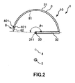
- FIG. 2 is a cross sectional view taken along line A-A in FIG. 1 .
- FIG. 3 is a cross sectional view of the puncture device of the puncture apparatus depicted in FIG. 1 ;
- FIG. 3(a) is a cross sectional view taken along line B-B in FIG. 1 ;
- FIG. 3(b) is a cross sectional view taken along line C-C in FIG. 3(a) .
- FIG. 4 is a cross sectional view depicting a state in which a balloon catheter is inserted in a urethral-insertion member of the puncture apparatus depicted in FIG. 1 .
- FIGS. 5 to 9 are views illustrating an operation procedure of the puncture apparatus depicted in FIG. 1 .
- FIG. 5(a) , FIG. 6(a) , FIG. 7(a) and FIG. 8(a) are lateral views;
- FIG. 5(b) is a cross sectional view taken along line D-D in FIG. 5(a) ;
- FIG. 6(b) is a cross sectional view taken along line E-E in of FIG. 6(a) ;
- FIG. 7(b) is a cross sectional view taken along line F-F in FIG. 7(a) ;
- FIG. 8(b) is a cross sectional view taken along line G-G in FIG. 8(a) ;
- FIG. 9 is a view corresponding to the cross sectional view taken along line D-D in FIG. 5(a) .
- FIG. 5(b) , FIG. 6(b) , FIG. 7(b) , FIG. 8(b) and FIG. 9 slanting lines for a living body are omitted so as to be easily viewable.
- the puncture apparatus 1 depicted in the figures is an apparatus to be used for the treatment of woman's urinary incontinence, namely, to be used when a living body tissue supporting indwelling article for the treatment of urinary incontinence is implanted into the inside of the living body.
- the living body tissue supporting indwelling article is a implantable tool for the treatment of woman's urinary incontinence, namely, an elongated tool to be implanted into the living body for supporting the urethra (living body tissue), for example, a tool for supporting, for example, when it is intended to move the urethra to the vaginal wall side, the urethra tension-free or so as to pull the urethra in a direction in which the urethra is spaced away from the vaginal wall.
- the living body tissue supporting indwelling article it is possible to use, for example, an elongated object having flexibility.
- the puncture apparatus 1 includes a puncture device 10 for puncturing a living body tissue, a urethral-insertion member 4 of a longitudinal shape for being inserted into a urethra, a vaginal-insertion member 5 of a longitudinal shape for being inserted into a vagina, and a supporting member (restriction means) 2 for supporting the urethral-insertion member 4, the vaginal-insertion member 5 and a puncture member 3 (hereinafter described) of the puncture device 10.
- a puncture device 10 for puncturing a living body tissue
- a vaginal-insertion member 5 of a longitudinal shape for being inserted into a vagina
- a supporting member (restriction means) 2 for supporting the urethral-insertion member 4, the vaginal-insertion member 5 and a puncture member 3 (hereinafter described) of the puncture device 10.
- the puncture device 10 includes a puncture needle 31 for puncturing a living body tissue, a puncture member 3 having a shaft portion 33 and a connection portion 32 for connecting the puncture needle 31 and the shaft portion 33 to each other, and an indwelling article assembly 8 having a needle tip portion 82 positioned at the distal end of the puncture needle 31 and configured to puncture a living body tissue and a living body tissue supporting indwelling article 81.
- the puncture needle 31 has a form of a pipe and has a hollow portion 312, and the living body tissue supporting indwelling article 81 is accommodated in the hollow portion 312.
- the indwelling article assembly 8 has the living body tissue supporting indwelling article 81 in the form of a belt for attaching to a living body tissue, and the needle tip portion 82 fixed to a distal end portion of the living body tissue supporting indwelling article 81 for puncturing a living body tissue.
- the living body tissue supporting indwelling article 81 of the indwelling article assembly 8 is called "sling."
- the living body tissue supporting indwelling article 81 and the needle tip portion 82 are implanted into a living body.
- the living body tissue supporting indwelling article 81 has a net-like form and can be configured, for example, as an article braided in a net-like form (lattice form) of crossing linear bodies, namely, as a braided body having a net-like form.
- the linear bodies may be, for example, those having a circular transverse sectional shape, those having a flattened transverse sectional shape, namely, those of a belt-like form (ribbon form), and so forth.
- the living body tissue supporting indwelling article 81 is not limited to that of the net-like form described above.
- the needle tip portion 82 has, at an apex portion thereof, a rounded and non-sharp needle tip for puncturing a living body tissue. Consequently, when the needle tip portion 82 is implanted in a living body, the living body tissue can be prevented from being damaged.
- the needle tip portion 82 is fixed at a proximal end portion thereof to the distal end portion of the living body tissue supporting indwelling article 81.
- a pair of protrusions 821 are formed at an outer circumferential portion of the proximal end portion of the needle tip portion 82 such that they protrude toward a direction of the proximal end.
- the protrusions 821 are arranged in an opposing relationship to each other across the center axis of the puncture needle 31. Further, the protrusions 821 are spaced from each other by a greater amount in the proximal end side than in the distal end side. Consequently, the needle tip portion 82 can be prevented from returning in the opposite direction to the puncturing direction of the needle tip portion 82, and an anchor effect can be obtained.
- constituent materials of the needle tip portion 82 and the living body tissue supporting indwelling article 81 are not limited specifically and can be configured using, for example, various resin materials and so forth having biocompatibility.
- the living body tissue supporting indwelling article 81 is accommodated in the hollow portion 312 of the puncture needle 31, and the needle tip portion 82 is held removably, namely, detachably, at a distal end portion of the puncture needle 31.
- the urethral-insertion member 4 is firmly fixed to the supporting member 2.
- the urethral-insertion member 4 has a straight tubular shape made of non-flexible hard material, and an opening at the proximal end thereof is open at the proximal end face of the supporting member 2.
- a balloon catheter 11 which includes an expandable and contractible balloon 111 at the distal end portion thereof as depicted in FIG. 4 .
- the balloon 111 in a contracted state is indicated by a solid line
- the balloon 111 in an expanded state is indicated by an alternate long and two-short dashes line.
- the balloon 111 of the balloon catheter 11 functions as a restriction unit for restricting the position of the urethral-insertion member 4 in the axial direction (longitudinal direction) inside the urethra. More specifically, when the puncture apparatus 1 is to be used, the balloon 111 is inserted into the bladder of a patient, and the positional relation in the axial direction between the balloon catheter 11 and the urethral-insertion member 4 is fixed. Besides, the balloon 111 is caught by the bladder neck in a state in which the balloon 111 is expanded, and consequently, the position of the urethral-insertion member 4 with respect to the bladder and the urethra is fixed.
- a balloon expanding tool such as, for example, a syringe not depicted is connected to a port not depicted which communicates with a lumen not depicted which communicates with the balloon 111 of the balloon catheter 11. Then, operating fluid supplied from the balloon expanding tool is sent into or extracted from the inside of the balloon 111 thorough the aforementioned lumen to carry out expansion and contraction of the balloon 111.
- the operating fluid for the expansion of the balloon it is possible to use liquid such as, for example, physiological salt solution or gas.
- the balloon catheter 11 for the urination of the patient when the puncture apparatus 1 is to be used.
- a marker 41 is provided at an outer circumferential portion of the urethral-insertion member 4.
- the marker 41 is arranged such that the marker 41 is positioned at the urethral orifice when the urethral-insertion member 4 is inserted into the urethra and the distal end portion of the urethral-insertion member 4 is positioned just in front of the bladder.
- the vaginal-insertion member 5 is firmly fixed to the supporting member 2.
- the vaginal-insertion member 5 may otherwise be removably provided on the supporting member 2.
- the vaginal-insertion member 5 has a form of a straight bar. Further, the distal end portion of the vaginal-insertion member 5 is rounded. Consequently, it is possible to insert the vaginal-insertion member 5 smoothly into the vagina.
- vaginal-insertion member 5 is arranged in a spaced relationship by a predetermined distance from the urethral-insertion member 4 below the urethral-insertion member 4 such that the axial line thereof and the axial line of the urethral-insertion member 4 extend in parallel to each other.
- constituent materials of the vaginal-insertion member 5, the urethral-insertion member 4 and the supporting member 2 are not limited specifically, and it is possible to use, for example, various kinds of resin materials.
- the puncture member 3 of the puncture device 10 is installed, at the shaft portion 33 thereof which serves as a rotational shaft, for rotational movement on the supporting member 2.
- the shaft portion 33 is arranged in a spaced relationship by a predetermined distance from the urethral-insertion member 4 above the urethral-insertion member 4 such that the axial line thereof and the axial line of the urethral-insertion member 4 extend in parallel to each other. Further, as viewed from an axial direction of the shaft portion 33, the shaft portion 33, urethral-insertion member 4 and vaginal insertion member 5 are arranged on a straight line.
- the shaft portion 33 passes through the supporting member 2 in the leftward and rightward direction in FIG. 1 .
- a flange 331 and another flange 332 are formed, respectively, with the supporting member 2 interposed therebetween. The movement of the shaft portion 33 in the axial direction with respect to the supporting member 2 is blocked by the flanges 331 and 332.
- the puncture needle 31 has a form of a pipe and has a hollow portion 312.
- the hollow portion 312 is open at the distal end and closed at the proximal end thereof.
- the puncture needle 31 has a flattened shape as viewed in the longitudinal direction thereof.
- the transverse sectional shape of the puncture needle 31 corresponds to the transverse sectional shape of the living body tissue supporting indwelling article 81. Consequently, a puncture hole 500 of a shape corresponding to that of the living body tissue supporting indwelling article 81 can be formed in a patient, and the indwelling article assembly 8 can be implanted more readily and appropriately.
- the puncture needle 31 is curved in an arc centered at the shaft portion 33. Further, in FIG. 1 , the axial line of the puncture needle 31 and the axial line of the shaft portion 33 cross orthogonally with each other. Consequently, when the puncture member 3 is rotationally moved, the needle tip of the puncture needle 31 moves along the arc described above in a plane perpendicular to the axial line of the shaft portion 33, namely, in a plane having a normal line at the axial line.
- the distal end of the puncture needle 31 is directed in a counterclockwise direction in FIG. 2
- the direction of the distal end of the puncture needle 31 is not limited to this and the distal end of the puncture needle 31 may be directed in a clockwise direction in FIG. 2 .
- the puncture needle 31 is arranged at the proximal end side with respect to a distal end portion of the urethral-insertion member 4 in the axial direction of the urethral-insertion member 4.
- the puncture needle 31 may be arranged at a position same as that of a distal end portion of the urethral-insertion member 4 in the axial direction of the urethral-insertion member 4 or may be arranged at the distal end side with respect to the distal end portion of the urethral-insertion member 4.
- the supporting member 2 restricts the positional relationship between the puncture device 10 and the urethral-insertion member 4 so that, when the puncture device 10 is rotationally moved and punctuates a living body tissue, the needle tip of the needle tip portion 82 passes at the farther-position side from the center 311 of the puncture needle 31 than the urethral-insertion member 4 or an extension line of the urethral-insertion member 4, namely, below the urethral-insertion member 4 or the extension line of the urethral-insertion member 4.
- the center 311 of the puncture needle 31 is the center of the arc of the puncture needle 31. In other words, the center 311 of the puncture needle 31 is the center of the rotational movement of the puncture needle 31 (puncture device 10).
- the supporting member 2 restricts the positional relationship between the puncture device 10 and the vaginal insertion member 5 so that, when the puncture device 10 is rotationally moved and punctures a living body, the needle tip of the needle tip portion 82 may not collide with the vaginal insertion member 5 and an extension line of the vaginal insertion member 5.
- the supporting member 2 restricts the positional relationship among the puncture device 10, urethral-insertion member 4 and vaginal insertion member 5 so that, when the puncture device 10 is rotationally moved and punctures a living body, the needle tip of the needle tip portion 82 passes between the urethral-insertion member 4 or the extension line of the urethral-insertion member 4 and the vaginal insertion member 5 or the extension line of the vaginal insertion member 5.
- the puncture device 10 can puncture a living body tissue avoiding the urethra and the vaginal wall, and the puncture device 10 can be prevented from puncturing the urethra and from puncturing the vaginal wall.
- the operator can safely prevent the operator itself from being punctured at the fingertip thereof by the puncture device 10.
- the center angle of the arc of the puncture needle 31 is not restricted particularly but is set suitably in response to various conditions, the center angle is set such that, when a living body tissue is punctured by the puncture device 10, the needle tip portion 82 of the puncture device 10 enters into the body from the body surface at one side of a patient, passes below the urethra and can move to a position in the proximity of the body surface at another side of the patient.
- the center angle ⁇ 1 of the arc of the puncture needle 31 and the needle tip portion 82 preferably is 150 to 270 degrees, more preferably is 170 to 250 degrees, and most preferably is 190 to 230 degrees.
- the needle tip portion 82 can enter into the body from the body surface at one side of the patient, pass below the urethra and be positioned in the proximity of the body surface at the other side without penetrating the body surface at the other side.
- a grip unit 34 is provided as an operation unit for operating the puncture device 10 to move rotationally is provided at a proximal end portion of the shaft portion 33.
- the shape of the grip unit 34 in the present embodiment has a form of a rectangular solid.
- the grip unit 34 is gripped by the fingers of a hand and is moved rotationally in a predetermined direction. Note that it is needless to say that the shape of the grip unit 34 is not to be limited to this.
- constituent material of the puncture member 3 is not limited specifically, and such various metal materials as stainless steel, aluminum or aluminum alloy and titanium or titanium alloy can be used as the constituent material of the puncture member 3.
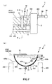
- the puncture apparatus 1 is mounted on a patient as depicted in FIG. 5 .
- the urethral-insertion member 4 of the puncture apparatus 1 is inserted into the urethra 100 of the patient and the vaginal-insertion member 5 is inserted into the vagina 200 of the patient.
- the insertion is carried out such that the marker 41 is positioned at the urethral orifice or on the front side of the urethral orifice. Consequently, the distal end portion of the urethral-insertion member 4 can be arranged on the front side of the bladder.
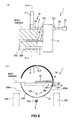
- the grip unit 34 is grasped as depicted in FIGS. 6 and 7 and rotationally moves the puncture device 10 counterclockwise in FIG. 6(b) and FIG. 7(b) .
- the needle tip of the needle tip portion 82 of the puncture device 10 moves counterclockwise in FIG. 6(b) and FIG. 7(b) along the arc thereof; punctures the body surface at an inguinal region of the patient on the left side in FIG. 6(b) and FIG. 7(b) or at a region in the vicinity of the same; enters into the body; passes an obturator foramen 400a of a pelvis 300; passes below the urethra 100, namely, passes between the urethra 100 and the vagina 200; passes an obturator foramen 400b of the pelvis 300; and moves to the proximity of an inguinal region on the right side in FIG. 6(b) and FIG.
- a puncture hole 500 is formed which extends from the body surface at the inguinal region at the left side in FIG. 6(b) and FIG. 7(b) or at a region in the proximity of the inguinal region past the obturator foramen 400a, a region between the urethra 100 and the vagina 200 and the obturator foramen 400b to a position in the proximity of the body surface at the inguinal region at the right side in FIG. 6(b) and FIG. 7(b) or at a region in the proximity of the inguinal region.
- the grip unit 34 is grasped and the puncture device 10 is rotationally moved clockwise in FIG. 8 .
- the indwelling article assembly 8 is prevented from returning in the opposite direction to the puncturing direction by the protrusions 821 of the needle tip portion 82 thereof. Further, the distal end of the puncture needle 31 moves in the clockwise direction in FIG. 8 along the arc thereof; passes through the obturator foramen 400b of the pelvis 300; passes below the urethra 100; namely; passes a location between the urethra 100 and the vagina 200; passes through the obturator foramen 400a of the pelvis 300; and comes out to the outside of the body from the body surface at the inguinal region at the left side in FIG. 8 or at a region in the proximity of the inguinal region. In other words, the puncture needle 31 is pulled out to the outside of the body.
- the indwelling article assembly 8, namely, the living body tissue supporting indwelling article 81 is implanted into the living body in such a manner as described above.
- the puncture apparatus 1 is removed from the patient.
- the urethral-insertion member 4 is pulled out from within the urethra 100 and the vaginal insertion member 5 is pulled out from within the vagina 200 of the patient.
- predetermined treatment is carried out, thereby ending the manual procedure.
- the puncture apparatus 1 when the living body tissue supporting indwelling article 81 is to be indwelled, the indwelling operation can be carried out only by a low invasive manual procedure such as puncturing of the puncture device 10. Since it is not necessary to carry out a high invasive incision or the like, the burden on the patient is light and also the safety of the patient is high.
- the puncture device 10 it is possible to puncture the living body by the puncture device 10 avoiding the urethra and the vaginal wall, and it is possible to prevent the puncture device 10 from puncturing the urethra and puncturing the vaginal wall. Therefore, safety can be achieved. Also the operator itself can prevent its fingertip from being punctured by the puncture device 10. Therefore, safety can be achieved.
- the living body tissue supporting indwelling article 81 can be implanted in very high safety and with certainty.
- the living body tissue supporting indwelling article 81 is accommodated in the hollow portion 312 of the puncture needle 31, the living body tissue supporting indwelling article 81 can be implanted readily.
- the puncture hole is not limited to this and may be a through-hole.
- the urethral-insertion member is not limited to that of a tubular shape, and may be, for example, a solid member or may be a hollow member which is closed up at one or both of the distal end portion and the proximal end portion thereof.
- an expandable and contractible balloon may be provided as a restriction unit for restricting the position of the urethral-insertion member in the axial direction inside the urethra.
- the puncture needle of the puncture device in the present embodiment is curved in an arc over an overall extent thereof
- the puncture needle is not limited to this and may have an arcuately curved portion only at part thereof. In other words, only it is necessary for the puncture needle to have an arcuately curved portion at least at part thereof.
- the puncture needle may have a curved portion at least at part thereof, and, for example, may be curved in an elliptical arc over an overall extent thereof or may have a portion curved in an elliptical arc only at part thereof. In other words, the puncture needle may have a portion curved in an elliptical arc at least at part thereof.
- FIG. 10 is a side elevational view depicting a second embodiment of the puncture apparatus of the present invention.
- FIG. 11 is a cross sectional view taken along line H-H in FIG. 10 .
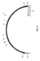
- FIG. 12 is a cross sectional view of a puncture device of the puncture apparatus.
- FIGS. 13 to 19 are views illustrating an operation procedure of the puncture apparatus.
- FIG. 13(a) , FIG. 14(a) and FIG. 15(a) are lateral views;
- FIG. 13(b) is a cross sectional view taken along line I-I in FIG. 13(a) ;
- FIG. 14(b) is a cross sectional view taken along line J-J in FIG. 14(a) ;
- FIG. 15(b) is a cross sectional view taken along line K-K in FIG. 15(a) ;
- FIGS. 16 to 19 correspond to the cross sectional view taken along line I-I in FIG. 13(a) .
- FIG. 13(b) , FIG. 14(b) , FIG. 15(b) and FIGS. 16 to 19 slanting lines for a living body are omitted so as to be easily viewable.
- FIG. 10 the left side in FIG. 10 , FIG. 13(a) , FIG. 14(a) , and FIG. 15(a) is “distal end” and the right side is “proximal end.”
- the living body tissue supporting indwelling article 81a of the indwelling article assembly 8 includes an indwelling article main body 810, a string (first string member) 83 connected at the proximal end thereof to the distal end of the indwelling article main body 810, a string (second string member) 84 connected at the distal end thereof to the proximal end of the indwelling article main body 810, and a holding member 85 connected to the proximal end of the string 84.
- the string 83 is fixed at a proximal end portion thereof to a distal end portion of the indwelling article main body 810
- the string 84 is fixed at a distal end portion thereof to a proximal end portion of the indwelling article main body 810.
- the holding member 85 is fixed to a proximal end portion of the string 84 and is held removably, namely, detachably, on the hollow portion 312 at a proximal end portion of the puncture needle 31.
- the indwelling article main body 810 is similar to the living body tissue supporting indwelling article 81 in the first embodiment.
- the holding member 85 in the present embodiment has a spherical shape. Note that it is needless to say that the shape of the holding member 85 is not limited to this.
- constituent materials of the strings 83 and 84 are not limited specifically and can be configured, for example, using various resin materials, fiber materials and so forth.
- constituent material of the holding member 85 is not limited specifically and can be configured, for example, using various resin materials.
- a needle tip portion 86 of the indwelling article assembly 8 has a sharp needle tip at the distal end thereof. This needle tip portion 86 is fixed to a distal end portion of the string 83.
- the needle tip portion 86 and the holding member 85 of the indwelling article assembly 8 are not implanted in a living body, but the indwelling article main body 810 of the living body tissue supporting indwelling article 81a and part of the strings 83 and 84 are implanted in a living body.
- the center angle of the arc of the puncture needle 31 is not limited specifically and is set suitably in response to various conditions. However, the center angle is set such that, when the puncture device 10 punctures a living body tissue, the needle tip portion 86 of the puncture device 10 can enter into the body from the body surface at one side of the patient, pass below the urethra and protrude to the outside of the body from the body surface at the other side.
- the center angle ⁇ 2 of the arc of the puncture needle 31 and the needle tip portion 86 preferably is 150 to 270 degrees, more preferably is 170 to 250 degrees, and most preferably is 190 to 230 degrees.
- the needle tip portion 86 can enter into the body from the body surface at one side of the patient, pass below the urethra and protrude to the outside of the body from the body surface at the other side with certainty.
- the puncture apparatus 1 is mounted on a patient as depicted in FIG. 13 .
- the urethral-insertion member 4 of the puncture apparatus 1 is inserted into the urethra 100 of the patient and the vaginal-insertion member 5 is inserted into the vagina 200 of the patient.
- the insertion is carried out such that the marker 41 is positioned at the urethral orifice or on the front side of the urethral orifice. Consequently, the distal end portion of the urethral-insertion member 4 can be arranged on the front side of the bladder.
- the grip unit 34 is grasped as depicted in FIGS. 14 and 15 and rotationally moves the puncture device 10 counterclockwise in FIG. 14(b) and FIG. 15(b) .
- the needle tip of the needle tip portion 86 of the puncture device 10 moves counterclockwise in FIG. 14(b) and FIG. 15(b) along the arc thereof; punctures the body surface at an inguinal region of the patient on the left side in FIG. 15(b) and FIG. 16(b) or at a region in the vicinity of the same; enters into the body; passes an obturator foramen 400a of a pelvis 300; passes below the urethra 100, namely, passes between the urethra 100 and the vagina 200; passes an obturator foramen 400b of the pelvis 300; and protrudes to the outside of the body from the body surface at the inguinal region at the right side in FIG. 14(b) and FIG.
- a puncture hole 600 is formed which extends from the body surface at an inguinal region on the left side in FIG. 14(b) and FIG. 15(b) or at a region in the vicinity of the same to the body surface at an inguinal region on the right side in FIG. 14(b) and FIG. 15(b) or at a region in the vicinity of the same while passing through the obturator foramen 400a, between the urethra 100 and the vagina 200 and through the obturator foramen 400b.
- the needle tip portion 86 is removed from the distal end portion of the puncture needle 31 as depicted in FIG. 16 , and the grip unit 34 is grasped as depicted in FIG. 17 to rotationally move the puncture device 10 clockwise in FIG. 8 .
- the distal end of the puncture needle 31 moves clockwise in FIG. 17 along the arc thereof; passes through the obturator foramen 400b of the pelvis 300; passes below the urethra 100, namely, passes between the urethra 100 and the vagina 200; passes through the obturator foramen 400a of the pelvis 300; and goes out to the outside of the body from the body surface at an inguinal region at the left side in FIG. 17 or at a region in the proximity of the same. That is, the puncture needle 31 is removed to the outside of the body.
- the holding member 85 is removed from the distal end of the hollow portion 312 of the puncture needle 31. Further, the puncture apparatus 1 is removed from the patient. In particular, the urethral-insertion member 4 is pulled out from within the urethra 100, and the vaginal insertion member 5 is pulled out from within the vagina 200 of the patient.
- the strings 83 and 84 are pulled individually by predetermined forces as depicted in FIG. 18 to adjust the position of the indwelling article main body 810 with respect to the urethra 100, and unnecessary portions of the strings 83 and 84 are cut away. Then, predetermined treatment is carried out, thereby ending the manual procedure.
- the indwelling article main body 810 is implanted into the living body tissue in this manner.
- the fixation of the needle tip portion is not limited to this, and the needle tip portion may be held removably, namely, detachably, on a string.
- FIG. 20 is a cross sectional view depicting a puncture device according to a third embodiment of the puncture apparatus of the present invention.
- the puncture needle 31 of the puncture device 10 has a needle tip portion 35 at a distal end portion thereof.
- the needle tip portion 35 is fixed to or integrated with the distal end portion of the puncture needle 31.
- the needle tip portion 35 has a sharp needle tip at the distal end thereof.
- the hollow portion 312 of the puncture needle 31 is open at both of the distal end and the proximal end thereof.
- the puncture device 10 has a pusher not depicted for pushing the string 83 of the living body tissue supporting indwelling article 81a in a direction toward the distal end.
- the pusher when it is to be used, the pusher is inserted into the hollow portion 312 from the proximal end opening of the puncture needle 31, and the string 83 of the living body tissue supporting indwelling article 81a is pushed to move in the direction toward the distal end by the pusher so that the string 83 protrudes from the distal end opening 351 of a needle tip portion 35.
- FIG. 21 is a cross sectional view depicting a puncture device according to a fourth embodiment of the puncture apparatus of the present invention.
- the puncture needle 31 has a variable length.
- the puncture needle 31 includes a needle main body 313 for puncturing a living body tissue, and an extension needle 314 provided for relative movement to the needle main body 313 along a longitudinal direction of the needle main body 313 for puncturing a living body tissue.
- the puncture needle 31 is extended by the extension needle 314 moving in a direction toward the distal end of the needle main body 313 with respect to the needle main body 313.
- a hollow portion of the needle main body 313 and the extension needle 314 is open at the distal end and the proximal end thereof.
- the needle tip portion 82 of the indwelling article assembly 8 is held removably, namely, detachably, at a distal end portion of the extension needle 314.
- the puncture device 10 includes, as extension means for moving the extension needle 314 in the direction toward the distal end of the needle main body 313 with respect to the needle main body 313, a pusher not depicted which pushes the extension needle 314 to move to the direction toward the distal end of the needle main body 313.
- the pusher when it is to be used, the pusher is inserted into the hollow portion of the extension needle 314 from the proximal end opening so that the extension needle 314 is pushed in the direction toward the distal end thereof by the pusher to extend the puncture needle 31.
- FIG. 22 is a cross sectional view depicting a puncture device in a fifth embodiment of the puncture apparatus of the present invention.
- the puncture needle 31 has a variable length.
- the puncture needle 31 includes a needle main body 313 for puncturing a living body tissue, and an extension needle 315 provided for relative movement to the needle main body 313 along a longitudinal direction of the needle main body 313 for puncturing a living body tissue.
- the puncture needle 31 is extended by movement of the extension needle 315 in a direction toward the distal end of the needle main body 313 with respect to the needle main body 313.
- a hollow portion of the needle main body 313 and the extension needle 315 is open at both of the distal end and the proximal end thereof.
- the extension needle 315 has a needle tip portion 35 at a distal end portion thereof.
- the needle tip portion 35 is fixed to or integrated with the distal end portion of the extension needle 315.
- the needle tip portion 35 has a sharp needle tip at the distal end thereof.
- the puncture device 10 has a first pusher not depicted for pushing the string 83 of the living body tissue supporting indwelling article 81a to move in a direction toward the distal end.
- the first pusher when it is used, the first pusher is inserted into the hollow portion of the extension needle 315 from the proximal end opening so that the string 83 of the living body tissue supporting indwelling article 81a is pushed in the direction toward the distal end by the first pusher to protrude from the distal end opening 351 of the needle tip portion 35.
- the puncture device 10 includes, as extension means for moving the extension needle 315 in the direction toward the distal end of the needle main body 313 with respect to the needle main body 313 to extend the puncture needle 31, a second pusher for pushing the extension needle 315 to move in the direction toward the distal end of the needle main body 313.
- the second pusher when it is to be used, the second pusher is inserted into the hollow portion of the extension needle 315 from the proximal end opening of the same so that the extension needle 315 is pushed in the direction toward the distal end by the second pusher to extend the puncture needle 31.
- FIG. 23 is a side elevational view depicting a sixth embodiment of the puncture apparatus of the present invention.
- FIG. 24 is a bottom plan view depicting a urethral insertion member of the puncture apparatus depicted in FIG. 23 , namely, a view of the urethral-insertion member as viewed from the lower side in FIG. 23 .
- FIG. 25 is a plan view depicting a vaginal insertion member of the puncture apparatus depicted in FIG. 23 , namely, a view of the vaginal insertion member as viewed from the upper side in FIG. 23 .
- the puncture apparatus 1 of the sixth embodiment is configured such that the positional relationship between the urethral-insertion member 4 and the vaginal insertion member 5 is changeable, in other words, the angle of the axial line of the urethral-insertion member 4 is changeable.
- the supporting member 2 includes a urethral-insertion member supporting mechanism 21 capable of supporting the urethral-insertion member 4 with the angle of the axial line of the urethral-insertion member 4 changed.
- the urethral-insertion member supporting mechanism 21 is configured such that it can support the urethral-insertion member 4 in such a manner that a distal end portion of the urethral-insertion member 4 is directed obliquely upwardly as indicated by an alternate long and two short dashes line in FIG. 23 and can support the urethral-insertion member 4 in such a manner that the distal end portion of the urethral-insertion member 4 is directed obliquely downwardly.
- the supporting member 2 includes a vaginal insertion member supporting mechanism 22 which can support the vaginal insertion member 5 with the angle of the axial line of the vaginal insertion member 5 changed.
- the vaginal insertion member supporting mechanism 22 is configured such that it can support the vaginal insertion member 5 in such a manner that a distal end portion of the vaginal insertion member 5 is directed obliquely downwardly as indicated by an alternate long and two short dashes line in FIG. 23 and can support the vaginal insertion member 5 in such a manner that the distal end portion of the vaginal insertion member 5 is directed obliquely upwardly.
- the thickness of a living body tissue between the urethra and the vagina can be increased by arranging the urethral-insertion member 4 and the vaginal insertion member 5 so as to have inclined axial lines such that the distance between the axial line of the urethral-insertion member 4 and the axial line of the vaginal insertion member 5 increases toward the distal end side. Consequently, the puncture device 10 can puncture a living body tissue between the urethra and the vagina readily and with certainty.
- the urethral-insertion member 4 and the vaginal insertion member 5 so as to have inclined axial lines such that the distance between the axial line of the urethral-insertion member 4 and the axial line of the vaginal insertion member 5 decreases toward the distal end side.
- the urethral-insertion member supporting mechanism 21 and the vaginal insertion member supporting mechanism 22 configure positional relationship changing means for changing the positional relationship between the urethral-insertion member 4 and the vaginal insertion member 5.
- the urethral-insertion member 4 has a recessed portion 42 at a lower face of a distal end portion thereof.
- the urethral-insertion member 4 has a lumen 43 formed along an axial direction thereof.
- the lumen 43 is open to the proximal end of the urethral-insertion member 4 and to a bottom face of the recessed portion 42, namely, to an upper face.
- a port 44 is provided at the proximal end of the urethral-insertion member 4 such that it is communicated with the lumen 43.
- a pump not depicted is connected to the port 44 through a pipe member not depicted.
- the inner wall of the urethra can be pulled with certainty by the urethral-insertion member 4, and the thickness of a living body tissue between the urethra and the vagina can be increased.
- the recessed portion 42, lumen 43, port 44, housing and pump configure suction means.
- vaginal insertion member 5 has a recessed portion 51 at an upper face of a distal end portion thereof.
- the vaginal insertion member 5 has a lumen 52 formed along an axial direction thereof.
- the lumen 52 is open to the proximal end of the vaginal insertion member 5 and a bottom face of the recessed portion 51, namely, a lower face of the recessed portion 51.
- a port 53 is provided at the proximal end of the vaginal insertion member 5 such that it is communicated with the lumen 52.
- a pump not depicted is connected to the port 53 through a housing not depicted such that, by carrying out suction by operation of the pump, a living body tissue in the vagina in the recessed portion 51, namely, the inner wall of the vagina, can be attracted.
- suction means is configured from the recessed portion 51, lumen 52, port 53, housing and pump.
- FIG. 26 is a view depicting a urethral-insertion member and a stylet in a seventh embodiment of the puncture apparatus of the present invention.
- FIG. 26(a) is a cross sectional view depicting the urethra-insertion member, and FIGS. 26(b) and 26(c) are side elevational views depicting the stylet.
- the seventh embodiment is described principally in regard to differences thereof from the sixth embodiment described hereinabove while description of similar items is omitted.
- the puncture apparatus 1 of the seventh embodiment includes a linear stylet 61 having a linear shape, and a curved stylet 62 curved at a distal end portion thereof.
- the urethral-insertion member 4 is configured from a tube member having flexibility and exhibiting a substantially linear state in a natural state in which no external force is applied thereto.
- the urethral-insertion member 4 includes, in addition to the lumen 43, a lumen 45 into which the linear stylet 61 and the curved stylet 62 are selectively inserted.
- the lumen 45 is formed to extend from the proximal end to a distal end portion of the urethral-insertion member 4. Further, the lumen 45 is closed up at the distal end thereof but is open at the proximal end thereof to the proximal end of the urethral-insertion member 4.
- a port not depicted is provided at the proximal end of the urethral-insertion member 4 such that it is communicated with the lumen 45 so that the linear stylet 61 or the curved stylet 62 can be inserted from the port.
- the urethral-insertion member 4 is placed into a linear state by the linear stylet 61. Consequently, the urethral-insertion member 4 can be inserted into the urethra readily and smoothly.
- the curved stylet 62 is inserted into the lumen 45, then the distal end portion of the urethral-insertion member 4 is curved by the curved stylet 62. Consequently, the thickness of a living body tissue between the urethra and the vagina can be increased. Consequently, the puncture device 10 can puncture a living body tissue between the urethra and the vagina readily and with certainty.
- the puncture device and the puncture apparatus of the present invention have been described on the basis of the embodiments depicted in the drawings, the present invention is not limited to them, and the configuration of each unit can be replaced with an arbitrary configuration having a similar function. Further, other arbitrary constructions may be added to the present invention.
- the present invention may be a combination of arbitrary two or more configurations of the embodiments described above.
- the vaginal insertion member may be omitted while the restriction means is configured such that it restricts only the positional relationship between the puncture needle (puncture member) and the vaginal insertion member.
- the puncture device and the puncture apparatus of the present invention are applied to an apparatus which is used when a living body tissue supporting indwelling article which can be implanted for the treatment of the woman's urinary incontinence is implanted into the living body.
- the application of the puncture device and the puncture apparatus of the present invention is not limited to this.
- the target of the application of the present invention includes an excretory disorder along with the weakening of the pelvic floor muscle group (urinary urgency, frequent urination, urinary incontinence, fecal incontinence, urinary retention, dysuria or the like), and a pelvic floor disorder including pelvic organ prolapse, vesicovaginal fistula, urethrovaginal fistula, pelvic pain or the like.
- pelvic organ prolapse there are include disorders of cystocele, enterocele, rectocele, hysterocele and the like.
- bladder, vagina, uterus, bowel and the like there are included bladder, vagina, uterus, bowel and the like.
- lessactive tissues there are included bones, muscles, fascias, ligaments and the like.
- pelvic floor disorders there are included an obturator fascia, a coccygeus fascia, a cardinal ligament, an uterosacral ligament, a sacrotuberous ligament and the like.
- a retropubic sling surgery for the procedure for interlocking an overactive tissue in the pelvic floor disorder with the lessactive tissue, there are included a retropubic sling surgery, a transobturator sling surgery (transobturator sling surgery, transobturator tape: TOT), a tension-free vaginal mesh (Tension-free Vaginal Mesh: TVM) surgery, a uterosacral ligament suspension (Uterosacral Ligament Suspension: USLS) surgery, a sacrospinous ligament fixation (Sacrospinous Ligament Fixation: SSLF) surgery, an iliococcygeus fascia fixation surgery, a coccygeus fascia fixation surgery, and the like.
- the puncture device of the present invention includes:
- the puncture apparatus of the present invention includes:
- the present invention it is possible to implant a living body tissue supporting indwelling article into a living body readily, and when the living body tissue supporting indwelling article is implanted, the burden on the patient is light and the safety of the patient is high. Also the safety of the operator is high.
- the puncture apparatus includes the restriction means for restricting the positional relation between the puncture device and the urethral-insertion member such that, when the puncture device rotationally moves to puncture the living body tissue, the needle tip portion passes the farther-position side from the center of rotational movement of the puncture device than the urethral-insertion member, for example, when the puncture apparatus is to be used for the treatment of woman's urinary incontinence, the urethral-insertion member of the puncture apparatus is inserted into a urethra, and the puncture device is rotationally moved so that the living body is punctured by the puncture device.
- the puncture device can puncture the living body avoiding the urethra. Consequently, the puncture device can be prevented from puncturing the urethra. Further, it is possible to prevent a fingertip of the operator from being punctured by the puncture device.
- the living body tissue supporting indwelling article for the treatment of urinary incontinence when the living body tissue supporting indwelling article for the treatment of urinary incontinence is to be implanted, no incision of the vaginal wall is required, and the living body tissue supporting indwelling article can be implanted by a low invasive manual procedure. Further, such a situation that, as in a case in which the vagina is incised, the living body tissue supporting indwelling article is exposed to the inside of the vagina through a wound caused by the incision or that such complications as an infection from the wound occur can be prevented. Therefore, the living body tissue supporting indwelling article can be implanted in very high safety and with certainty.
- the living body tissue supporting indwelling article is accommodated in the hollow portion of the puncture needle, the living body tissue supporting indwelling article can be implanted into a living body readily.
- the present invention has industrial applicability.
Landscapes
- Health & Medical Sciences (AREA)
- Life Sciences & Earth Sciences (AREA)
- Surgery (AREA)
- Veterinary Medicine (AREA)
- Engineering & Computer Science (AREA)
- Biomedical Technology (AREA)
- Heart & Thoracic Surgery (AREA)
- Animal Behavior & Ethology (AREA)
- General Health & Medical Sciences (AREA)
- Public Health (AREA)
- Medical Informatics (AREA)
- Molecular Biology (AREA)
- Nuclear Medicine, Radiotherapy & Molecular Imaging (AREA)
- Transplantation (AREA)
- Cardiology (AREA)
- Oral & Maxillofacial Surgery (AREA)
- Pathology (AREA)
- Vascular Medicine (AREA)
- Urology & Nephrology (AREA)
- Gynecology & Obstetrics (AREA)
- Pregnancy & Childbirth (AREA)
- Reproductive Health (AREA)
- Surgical Instruments (AREA)
- Prostheses (AREA)
Abstract
Description
- The present invention relates to a puncture device and a puncture apparatus.
- If a person suffers from a urinary incontinence, specifically if a person suffers from a stress urinary incontinence, then urine leakage is caused by application of abdominal pressure during a normal exercise or by laughing, coughing, sneezing and the like. The cause of this may be, for example, that the pelvic floor muscle which is a muscle for supporting the urethra is loosened by birth or the like.
- For the treatment of urinary incontinence, a surgical treatment is effective, in which there is used, for example, a belt-shaped living body tissue supporting indwelling article called "sling." The sling is indwelled inside the body and the urethra is supported by the sling (for example, refer to Patent Document 1). In order to indwell the sling inside the body, an operator would incise the vagina with a surgical knife, dissect a region between the urethra and the vagina, and communicate the dissected region and the outside with each other through an obturator foramen using a puncture needle or the like. Then, in such a state, the sling is indwelled into the body.
- However, if the vagina is incised once, then there is the possibility that there may occur such a situation that the sling is exposed to the inside of the vagina from a wound caused by the incision thereof, and there is the possibility that complications may be caused by an infection from the wound or the like. Further, since the vagina is incised, there is such a defect that the invasion is great and the burden on the patient is heavy. Further, there is the possibility that the urethra or the like may be damaged in the course of the procedure by the operator, and also there is the possibility that the operator itself may be damaged at its fingertip.
- Patent Document 1: Japanese Patent Laid-Open No.
2010-99499 - An object of the present invention is to provide a puncture device and a puncture apparatus by which a living body tissue supporting indwelling article can be implanted into a living body, in which the burden on the patient is light, the safety of the patient is high and also the safety of the operator is high.
- Such an object as just described is achieved by the present invention described below.
- The present invention provides a puncture device, including:
- a puncture needle having a hollow portion;
- a needle tip portion positioned at a distal end of the puncture needle and configured to puncture a living body tissue; and
- an elongated living body tissue supporting indwelling article accommodated in the hollow portion of the puncture needle and configured to be implanted into a living body to support the living body tissue.
- In the puncture device of the present invention, preferably the needle tip portion is removably held by or fixed to a distal end portion of the living body tissue supporting indwelling article.
- In the puncture device of the present invention, preferably the living body tissue supporting indwelling article includes:
- a belt-like element configured to attach to a living body tissue;
- a first string-like element connected at a proximal end thereof to a distal end of the belt-like element;
- a second string-like element connected at a distal end thereof to a proximal end of the belt-like element; and
- a holding member connected to a proximal end of the second string-like element and removably held by a proximal end of the puncture needle;
- the needle tip portion being removably held by or fixed to a distal end of the first string-like element.
- In the puncture device of the present invention, preferably the needle tip portion has an anchoring effect of preventing the needle tip portion from returning to an opposite direction to a puncturing direction of the needle tip portion.
- In the puncture device of the present invention, preferably the needle tip portion is fixedly mounted at or integrated with a distal end portion of the puncture needle.
- In the puncture device of the present invention, preferably the puncture needle has a variable length.
- In the puncture device of the present invention, preferably the puncture needle has a flattened shape as viewed in a longitudinal direction thereof, and
the living body tissue supporting indwelling article has a belt-like portion which is attached to a living body tissue. - Preferably, the puncture device of the present invention is configured such that the puncture needle has a portion curved along a longitudinal direction thereof.
- Preferably, the puncture device of the present invention is configured such that the puncture device is installed for rotational movement.
- According to the present invention, a puncture apparatus includes:
- the puncture device of the present invention;
- a urethral-insertion member of a longitudinal shape configured to be inserted into a urethra; and
- restriction means for restricting, when the puncture device is rotationally moved to puncture a living body tissue, a positional relationship between the puncture device and the urethral-insertion member such that the needle tip portion passes at a farther-position side from the center of rotational movement of the puncture device than the urethral-insertion member.
- Preferably the puncture apparatus of the present invention further includes:
- a vaginal insertion member of a longitudinal shape configured to be inserted into a vagina, wherein
- the restriction means restricts a positional relationship between the puncture device and the vaginal insertion member such that, when the puncture device is rotationally moved to puncture a living body tissue, the needle tip portion does not collide with the vaginal insertion member.
- Preferably, the puncture apparatus of the present invention is configured such that the puncture device has a shaft portion which provides a rotational axis of the rotational moment, and
the restriction means includes a supporting member which supports the shaft portion for rotational movement and supports the urethral-insertion member and the vaginal insertion member. - In the puncture apparatus of the present invention, preferably at least one of the urethral-insertion member and the vaginal insertion member has provided thereon suction means capable of attracting a living body tissue thereto.
- In the puncture apparatus of the present invention, preferably the positional relationship between the urethral-insertion member and the vaginal insertion member is variable.
- With the present invention, it is possible to implant a living body tissue supporting indwelling article into a living body readily, and when the living body tissue supporting indwelling article is implanted, the burden on the patient is light and the safety of the patient is high. Also the safety of the operator is high.
- Especially, where the puncture apparatus includes the restriction means for restricting the positional relation between the puncture device and the urethral-insertion member such that, when the puncture device rotationally moves to puncture the living body tissue, the needle tip portion passes the farther-position side from the center of rotational movement of the puncture device than the urethral-insertion member, for example, when the puncture apparatus is to be used for the treatment of woman's urinary incontinence, the urethral-insertion member of the puncture apparatus is inserted into a urethra, and the puncture device is rotationally moved so that the living body is punctured by the puncture device. Thereupon, since the needle tip portion passes the farther-position side from the center of rotational movement of the puncture device than the urethral-insertion member, the puncture needle can puncture the living body avoiding the urethra. Consequently, the puncture device can be prevented from puncturing the urethra. Further, it is possible to prevent a fingertip of the operator from being punctured by the puncture device.
- Further, when the living body tissue supporting indwelling article for the treatment of urinary incontinence is to be implanted, no incision of the vaginal wall is required, and the living body tissue supporting indwelling article can be implanted by a low invasive manual procedure. Further, such a situation that, as in a case in which the vagina is incised, the living body tissue supporting indwelling article is exposed to the inside of the vagina through a wound caused by the incision or that such complications as an infection from the wound occur can be prevented. Therefore, the living body tissue supporting indwelling article can be implanted in very high safety and with certainty.
- Further, since the living body tissue supporting indwelling article is accommodated in the hollow portion of the puncture needle, the living body tissue supporting indwelling article can be implanted into a living body readily.
-
- [
FIG. 1 ]
FIG. 1 is a lateral view depicting a first embodiment of a puncture apparatus of the present invention. - [
FIG. 2 ]
FIG. 2 is a cross sectional view taken along line A-A inFIG. 1 . - [
FIG. 3 ]
FIG. 3 is a cross sectional view of a puncture device of the puncture apparatus depicted inFIG. 1 . - [
FIG. 4 ]
FIG. 4 is a cross sectional view illustrating a state in which a balloon catheter is inserted in a urethral-insertion member of the puncture apparatus depicted inFIG. 1 . - [
FIG. 5 ]
FIG. 5 is a view illustrating an operation procedure of the puncture apparatus depicted inFIG. 1 . - [
FIG. 6 ]
FIG. 6 is a view illustrating an operation procedure of the puncture apparatus depicted inFIG. 1 . - [
FIG. 7 ]
FIG. 7 is a view illustrating an operation procedure of the puncture apparatus depicted inFIG. 1 . - [
FIG. 8 ]
FIG. 8 is a view illustrating an operation procedure of the puncture apparatus depicted inFIG. 1 . - [
FIG. 9 ]
FIG. 9 is a view illustrating an operation procedure of the puncture apparatus depicted inFIG. 1 . - [
FIG. 10 ]
FIG. 10 is a side elevational view depicting a second embodiment of the puncture apparatus of the present invention. - [
FIG. 11 ]
FIG. 11 is a cross sectional view taken along line H-H inFIG. 10 . - [
FIG. 12 ]
FIG. 12 is a cross sectional view of a puncture device of the puncture apparatus depicted inFIG. 10 . - [
FIG. 13 ]
FIG. 13 is a view illustrating an operation procedure of the puncture apparatus depicted inFIG. 10 . - [
FIG. 14 ]
FIG. 14 is a view illustrating an operation procedure of the puncture apparatus depicted inFIG. 10 . - [
FIG. 15 ]
FIG. 15 is a view illustrating an operation procedure of the puncture apparatus depicted inFIG. 10 . - [
FIG. 16 ]
FIG. 16 is a view illustrating an operation procedure of the puncture apparatus depicted inFIG. 10 . - [
FIG. 17 ]
FIG. 17 is a view illustrating an operation procedure of the puncture apparatus depicted inFIG. 10 . - [
FIG. 18 ]
FIG. 18 is a view illustrating an operation procedure of the puncture apparatus depicted inFIG. 10 . - [
FIG. 19 ]
FIG. 19 is a view illustrating an operation procedure of the puncture apparatus depicted inFIG. 10 . - [
FIG. 20 ]
FIG. 20 is a cross sectional view depicting a puncture device according to a third embodiment of the puncture apparatus of the present invention. - [
FIG. 21 ]
FIG. 21 is a cross sectional view depicting a puncture device according to a fourth embodiment of the puncture apparatus of the present invention. - [
FIG. 22 ]
FIG. 22 is a cross sectional view depicting a puncture device according to a fifth embodiment of the puncture apparatus of the present invention. - [
FIG. 23 ]
FIG. 23 is a side elevational view depicting a sixth embodiment of the puncture apparatus of the present invention. - [
FIG. 24 ]
FIG. 24 is a bottom plan view depicting a urethral-insertion member of the puncture apparatus depicted inFIG. 23 . - [
FIG. 25 ]
FIG. 25 is a top plan view depicting a vaginal insertion member of the puncture apparatus depicted inFIG. 23 . - [
FIG. 26 ]
FIG. 26 is a view depicting a urethral-insertion member and stylet in a seventh embodiment of the puncture apparatus of the present invention. - In the following, the puncture device and the puncture apparatus of the present invention is described in detail based on preferred embodiments depicted in the accompanying drawings.
-
FIG. 1 is a lateral view depicting a first embodiment of the puncture apparatus of the present invention.FIG. 2 is a cross sectional view taken along line A-A inFIG. 1 .FIG. 3 is a cross sectional view of the puncture device of the puncture apparatus depicted inFIG. 1 ;FIG. 3(a) is a cross sectional view taken along line B-B inFIG. 1 ;FIG. 3(b) is a cross sectional view taken along line C-C inFIG. 3(a) .FIG. 4 is a cross sectional view depicting a state in which a balloon catheter is inserted in a urethral-insertion member of the puncture apparatus depicted inFIG. 1 .FIGS. 5 to 9 are views illustrating an operation procedure of the puncture apparatus depicted inFIG. 1 . - Note that
FIG. 5(a) ,FIG. 6(a) ,FIG. 7(a) andFIG. 8(a) are lateral views;FIG. 5(b) is a cross sectional view taken along line D-D inFIG. 5(a) ;FIG. 6(b) is a cross sectional view taken along line E-E in ofFIG. 6(a) ;FIG. 7(b) is a cross sectional view taken along line F-F inFIG. 7(a) ; andFIG. 8(b) is a cross sectional view taken along line G-G inFIG. 8(a) ; andFIG. 9 is a view corresponding to the cross sectional view taken along line D-D inFIG. 5(a) . - Further, in
FIG. 5(b) ,FIG. 6(b) ,FIG. 7(b) ,FIG. 8(b) andFIG. 9 , slanting lines for a living body are omitted so as to be easily viewable. - In the following, description is given assuming that the left side in
FIG. 1 ,FIG. 4 ,FIG. 5(a) ,FIG. 6(a) ,FIG. 7(a) andFIG. 8(a) is "distal end" and the right side is "proximal end." - The
puncture apparatus 1 depicted in the figures is an apparatus to be used for the treatment of woman's urinary incontinence, namely, to be used when a living body tissue supporting indwelling article for the treatment of urinary incontinence is implanted into the inside of the living body. The living body tissue supporting indwelling article is a implantable tool for the treatment of woman's urinary incontinence, namely, an elongated tool to be implanted into the living body for supporting the urethra (living body tissue), for example, a tool for supporting, for example, when it is intended to move the urethra to the vaginal wall side, the urethra tension-free or so as to pull the urethra in a direction in which the urethra is spaced away from the vaginal wall. For the living body tissue supporting indwelling article, it is possible to use, for example, an elongated object having flexibility. - As depicted in
FIGS. 1 to 3 , thepuncture apparatus 1 includes apuncture device 10 for puncturing a living body tissue, a urethral-insertion member 4 of a longitudinal shape for being inserted into a urethra, a vaginal-insertion member 5 of a longitudinal shape for being inserted into a vagina, and a supporting member (restriction means) 2 for supporting the urethral-insertion member 4, the vaginal-insertion member 5 and a puncture member 3 (hereinafter described) of thepuncture device 10. - The
puncture device 10 includes apuncture needle 31 for puncturing a living body tissue, apuncture member 3 having ashaft portion 33 and aconnection portion 32 for connecting thepuncture needle 31 and theshaft portion 33 to each other, and anindwelling article assembly 8 having aneedle tip portion 82 positioned at the distal end of thepuncture needle 31 and configured to puncture a living body tissue and a living body tissue supportingindwelling article 81. Thepuncture needle 31 has a form of a pipe and has ahollow portion 312, and the living body tissue supportingindwelling article 81 is accommodated in thehollow portion 312. - The
indwelling article assembly 8 has the living body tissue supportingindwelling article 81 in the form of a belt for attaching to a living body tissue, and theneedle tip portion 82 fixed to a distal end portion of the living body tissue supportingindwelling article 81 for puncturing a living body tissue. The living body tissue supportingindwelling article 81 of theindwelling article assembly 8 is called "sling." In the present embodiment, the living body tissue supportingindwelling article 81 and theneedle tip portion 82 are implanted into a living body. - The living body tissue supporting
indwelling article 81 has a net-like form and can be configured, for example, as an article braided in a net-like form (lattice form) of crossing linear bodies, namely, as a braided body having a net-like form. The linear bodies may be, for example, those having a circular transverse sectional shape, those having a flattened transverse sectional shape, namely, those of a belt-like form (ribbon form), and so forth. - Note that it is needless to say that the living body tissue supporting
indwelling article 81 is not limited to that of the net-like form described above. - The
needle tip portion 82 has, at an apex portion thereof, a rounded and non-sharp needle tip for puncturing a living body tissue. Consequently, when theneedle tip portion 82 is implanted in a living body, the living body tissue can be prevented from being damaged. Theneedle tip portion 82 is fixed at a proximal end portion thereof to the distal end portion of the living body tissue supportingindwelling article 81. - Further, a pair of
protrusions 821 are formed at an outer circumferential portion of the proximal end portion of theneedle tip portion 82 such that they protrude toward a direction of the proximal end. Theprotrusions 821 are arranged in an opposing relationship to each other across the center axis of thepuncture needle 31. Further, theprotrusions 821 are spaced from each other by a greater amount in the proximal end side than in the distal end side. Consequently, theneedle tip portion 82 can be prevented from returning in the opposite direction to the puncturing direction of theneedle tip portion 82, and an anchor effect can be obtained. - Note that the constituent materials of the
needle tip portion 82 and the living body tissue supportingindwelling article 81 are not limited specifically and can be configured using, for example, various resin materials and so forth having biocompatibility. - In the
indwelling article assembly 8, the living body tissue supportingindwelling article 81 is accommodated in thehollow portion 312 of thepuncture needle 31, and theneedle tip portion 82 is held removably, namely, detachably, at a distal end portion of thepuncture needle 31. - In the present embodiment, the urethral-
insertion member 4 is firmly fixed to the supportingmember 2. The urethral-insertion member 4 has a straight tubular shape made of non-flexible hard material, and an opening at the proximal end thereof is open at the proximal end face of the supportingmember 2. Into the urethral-insertion member 4, it is possible to insert various kinds of elongated medical tools such as, for example, aballoon catheter 11, which includes an expandable andcontractible balloon 111 at the distal end portion thereof as depicted inFIG. 4 . InFIG. 4 , theballoon 111 in a contracted state is indicated by a solid line, and theballoon 111 in an expanded state is indicated by an alternate long and two-short dashes line. - The
balloon 111 of theballoon catheter 11 functions as a restriction unit for restricting the position of the urethral-insertion member 4 in the axial direction (longitudinal direction) inside the urethra. More specifically, when thepuncture apparatus 1 is to be used, theballoon 111 is inserted into the bladder of a patient, and the positional relation in the axial direction between theballoon catheter 11 and the urethral-insertion member 4 is fixed. Besides, theballoon 111 is caught by the bladder neck in a state in which theballoon 111 is expanded, and consequently, the position of the urethral-insertion member 4 with respect to the bladder and the urethra is fixed. - Note that a balloon expanding tool such as, for example, a syringe not depicted is connected to a port not depicted which communicates with a lumen not depicted which communicates with the
balloon 111 of theballoon catheter 11. Then, operating fluid supplied from the balloon expanding tool is sent into or extracted from the inside of theballoon 111 thorough the aforementioned lumen to carry out expansion and contraction of theballoon 111. As the operating fluid for the expansion of the balloon, it is possible to use liquid such as, for example, physiological salt solution or gas. - Further, it is possible to use the
balloon catheter 11 for the urination of the patient when thepuncture apparatus 1 is to be used. - A
marker 41 is provided at an outer circumferential portion of the urethral-insertion member 4. Themarker 41 is arranged such that themarker 41 is positioned at the urethral orifice when the urethral-insertion member 4 is inserted into the urethra and the distal end portion of the urethral-insertion member 4 is positioned just in front of the bladder. - In the present embodiment, the vaginal-
insertion member 5 is firmly fixed to the supportingmember 2. Note that the vaginal-insertion member 5 may otherwise be removably provided on the supportingmember 2. The vaginal-insertion member 5 has a form of a straight bar. Further, the distal end portion of the vaginal-insertion member 5 is rounded. Consequently, it is possible to insert the vaginal-insertion member 5 smoothly into the vagina. - Further, the vaginal-
insertion member 5 is arranged in a spaced relationship by a predetermined distance from the urethral-insertion member 4 below the urethral-insertion member 4 such that the axial line thereof and the axial line of the urethral-insertion member 4 extend in parallel to each other. - Note that the constituent materials of the vaginal-
insertion member 5, the urethral-insertion member 4 and the supportingmember 2 are not limited specifically, and it is possible to use, for example, various kinds of resin materials. - The
puncture member 3 of thepuncture device 10 is installed, at theshaft portion 33 thereof which serves as a rotational shaft, for rotational movement on the supportingmember 2. - Further, the
shaft portion 33 is arranged in a spaced relationship by a predetermined distance from the urethral-insertion member 4 above the urethral-insertion member 4 such that the axial line thereof and the axial line of the urethral-insertion member 4 extend in parallel to each other. Further, as viewed from an axial direction of theshaft portion 33, theshaft portion 33, urethral-insertion member 4 andvaginal insertion member 5 are arranged on a straight line. - The
shaft portion 33 passes through the supportingmember 2 in the leftward and rightward direction inFIG. 1 . On the distal end and the proximal end of theshaft portion 33, aflange 331 and anotherflange 332 are formed, respectively, with the supportingmember 2 interposed therebetween. The movement of theshaft portion 33 in the axial direction with respect to the supportingmember 2 is blocked by theflanges - The
puncture needle 31 has a form of a pipe and has ahollow portion 312. Thehollow portion 312 is open at the distal end and closed at the proximal end thereof. Further, thepuncture needle 31 has a flattened shape as viewed in the longitudinal direction thereof. In other words, the transverse sectional shape of thepuncture needle 31 corresponds to the transverse sectional shape of the living body tissue supportingindwelling article 81. Consequently, apuncture hole 500 of a shape corresponding to that of the living body tissue supportingindwelling article 81 can be formed in a patient, and theindwelling article assembly 8 can be implanted more readily and appropriately. - Further, the
puncture needle 31 is curved in an arc centered at theshaft portion 33. Further, inFIG. 1 , the axial line of thepuncture needle 31 and the axial line of theshaft portion 33 cross orthogonally with each other. Consequently, when thepuncture member 3 is rotationally moved, the needle tip of thepuncture needle 31 moves along the arc described above in a plane perpendicular to the axial line of theshaft portion 33, namely, in a plane having a normal line at the axial line. - Further, while, in the present embodiment, the distal end of the
puncture needle 31 is directed in a counterclockwise direction inFIG. 2 , the direction of the distal end of thepuncture needle 31 is not limited to this and the distal end of thepuncture needle 31 may be directed in a clockwise direction inFIG. 2 . - Further, in the present embodiment, the
puncture needle 31 is arranged at the proximal end side with respect to a distal end portion of the urethral-insertion member 4 in the axial direction of the urethral-insertion member 4. - Note that the
puncture needle 31 may be arranged at a position same as that of a distal end portion of the urethral-insertion member 4 in the axial direction of the urethral-insertion member 4 or may be arranged at the distal end side with respect to the distal end portion of the urethral-insertion member 4. - Here, the supporting
member 2 restricts the positional relationship between thepuncture device 10 and the urethral-insertion member 4 so that, when thepuncture device 10 is rotationally moved and punctuates a living body tissue, the needle tip of theneedle tip portion 82 passes at the farther-position side from thecenter 311 of thepuncture needle 31 than the urethral-insertion member 4 or an extension line of the urethral-insertion member 4, namely, below the urethral-insertion member 4 or the extension line of the urethral-insertion member 4. Note that thecenter 311 of thepuncture needle 31 is the center of the arc of thepuncture needle 31. In other words, thecenter 311 of thepuncture needle 31 is the center of the rotational movement of the puncture needle 31 (puncture device 10). - Further, the supporting
member 2 restricts the positional relationship between thepuncture device 10 and thevaginal insertion member 5 so that, when thepuncture device 10 is rotationally moved and punctures a living body, the needle tip of theneedle tip portion 82 may not collide with thevaginal insertion member 5 and an extension line of thevaginal insertion member 5. - In particular, the supporting
member 2 restricts the positional relationship among thepuncture device 10, urethral-insertion member 4 andvaginal insertion member 5 so that, when thepuncture device 10 is rotationally moved and punctures a living body, the needle tip of theneedle tip portion 82 passes between the urethral-insertion member 4 or the extension line of the urethral-insertion member 4 and thevaginal insertion member 5 or the extension line of thevaginal insertion member 5. - Consequently, the
puncture device 10 can puncture a living body tissue avoiding the urethra and the vaginal wall, and thepuncture device 10 can be prevented from puncturing the urethra and from puncturing the vaginal wall. - Further, since the trajectory of the needle tip of the
needle tip portion 82 of thepuncture device 10 is determined, also the operator can safely prevent the operator itself from being punctured at the fingertip thereof by thepuncture device 10. - Further, although the center angle of the arc of the
puncture needle 31 is not restricted particularly but is set suitably in response to various conditions, the center angle is set such that, when a living body tissue is punctured by thepuncture device 10, theneedle tip portion 82 of thepuncture device 10 enters into the body from the body surface at one side of a patient, passes below the urethra and can move to a position in the proximity of the body surface at another side of the patient. - In particular, the center angle θ1 of the arc of the
puncture needle 31 and theneedle tip portion 82 preferably is 150 to 270 degrees, more preferably is 170 to 250 degrees, and most preferably is 190 to 230 degrees. - Consequently, when a living body tissue is punctured by the
puncture device 10, theneedle tip portion 82 can enter into the body from the body surface at one side of the patient, pass below the urethra and be positioned in the proximity of the body surface at the other side without penetrating the body surface at the other side. - Further, a
grip unit 34 is provided as an operation unit for operating thepuncture device 10 to move rotationally is provided at a proximal end portion of theshaft portion 33. The shape of thegrip unit 34 in the present embodiment has a form of a rectangular solid. When thepuncture device 10 is to be moved rotationally, thegrip unit 34 is gripped by the fingers of a hand and is moved rotationally in a predetermined direction. Note that it is needless to say that the shape of thegrip unit 34 is not to be limited to this. - Note that the constituent material of the
puncture member 3 is not limited specifically, and such various metal materials as stainless steel, aluminum or aluminum alloy and titanium or titanium alloy can be used as the constituent material of thepuncture member 3. - Now, an operation procedure of the
puncture apparatus 1, namely, a procedure when theindwelling article assembly 8 is implanted into a living body, is described. - First, the
puncture apparatus 1 is mounted on a patient as depicted inFIG. 5 . In particular, the urethral-insertion member 4 of thepuncture apparatus 1 is inserted into theurethra 100 of the patient and the vaginal-insertion member 5 is inserted into thevagina 200 of the patient. At the time, the insertion is carried out such that themarker 41 is positioned at the urethral orifice or on the front side of the urethral orifice. Consequently, the distal end portion of the urethral-insertion member 4 can be arranged on the front side of the bladder. - Then, the
grip unit 34 is grasped as depicted inFIGS. 6 and7 and rotationally moves thepuncture device 10 counterclockwise inFIG. 6(b) andFIG. 7(b) . - Consequently, the needle tip of the
needle tip portion 82 of thepuncture device 10 moves counterclockwise inFIG. 6(b) andFIG. 7(b) along the arc thereof; punctures the body surface at an inguinal region of the patient on the left side inFIG. 6(b) andFIG. 7(b) or at a region in the vicinity of the same; enters into the body; passes anobturator foramen 400a of apelvis 300; passes below theurethra 100, namely, passes between theurethra 100 and thevagina 200; passes anobturator foramen 400b of thepelvis 300; and moves to the proximity of an inguinal region on the right side inFIG. 6(b) andFIG. 7(b) or at a region in the proximity of the inguinal region. Note that the needle tip of theneedle tip portion 82 does not penetrate the body surface at the inguinal region on the right side or at a region in the proximity of the inguinal region. Consequently, in the patient, apuncture hole 500 is formed which extends from the body surface at the inguinal region at the left side inFIG. 6(b) andFIG. 7(b) or at a region in the proximity of the inguinal region past theobturator foramen 400a, a region between theurethra 100 and thevagina 200 and theobturator foramen 400b to a position in the proximity of the body surface at the inguinal region at the right side inFIG. 6(b) andFIG. 7(b) or at a region in the proximity of the inguinal region. - Then, as depicted in
FIG. 8 , thegrip unit 34 is grasped and thepuncture device 10 is rotationally moved clockwise inFIG. 8 . - Thereupon, the
indwelling article assembly 8 is prevented from returning in the opposite direction to the puncturing direction by theprotrusions 821 of theneedle tip portion 82 thereof. Further, the distal end of thepuncture needle 31 moves in the clockwise direction inFIG. 8 along the arc thereof; passes through theobturator foramen 400b of thepelvis 300; passes below theurethra 100; namely; passes a location between theurethra 100 and thevagina 200; passes through theobturator foramen 400a of thepelvis 300; and comes out to the outside of the body from the body surface at the inguinal region at the left side inFIG. 8 or at a region in the proximity of the inguinal region. In other words, thepuncture needle 31 is pulled out to the outside of the body. Theindwelling article assembly 8, namely, the living body tissue supportingindwelling article 81, is implanted into the living body in such a manner as described above. - Then, the
puncture apparatus 1 is removed from the patient. In particular, the urethral-insertion member 4 is pulled out from within theurethra 100 and thevaginal insertion member 5 is pulled out from within thevagina 200 of the patient. Then, predetermined treatment is carried out, thereby ending the manual procedure. - As described above, with the
puncture apparatus 1, when the living body tissue supportingindwelling article 81 is to be indwelled, the indwelling operation can be carried out only by a low invasive manual procedure such as puncturing of thepuncture device 10. Since it is not necessary to carry out a high invasive incision or the like, the burden on the patient is light and also the safety of the patient is high. - Further, it is possible to puncture the living body by the
puncture device 10 avoiding the urethra and the vaginal wall, and it is possible to prevent thepuncture device 10 from puncturing the urethra and puncturing the vaginal wall. Therefore, safety can be achieved. Also the operator itself can prevent its fingertip from being punctured by thepuncture device 10. Therefore, safety can be achieved. - Further, it is possible to prevent such a situation as in a conventional case in which the vagina is incised that the living body tissue supporting
indwelling article 81 is exposed to the inside of the vagina through a wound caused by the incision or that such complications as an infection from the wound occur. Therefore, the living body tissue supportingindwelling article 81 can be implanted in very high safety and with certainty. - Further, since the living body tissue supporting
indwelling article 81 is accommodated in thehollow portion 312 of thepuncture needle 31, the living body tissue supportingindwelling article 81 can be implanted readily. - Note that, although, in the present embodiment, one end portion of the puncture hole formed in the patient by the puncture device does not penetrate the body surface, the puncture hole is not limited to this and may be a through-hole.
- Further, the urethral-insertion member is not limited to that of a tubular shape, and may be, for example, a solid member or may be a hollow member which is closed up at one or both of the distal end portion and the proximal end portion thereof.
- Further, at the distal end portion of the urethral-insertion member, an expandable and contractible balloon may be provided as a restriction unit for restricting the position of the urethral-insertion member in the axial direction inside the urethra.
- Further, while the puncture needle of the puncture device in the present embodiment is curved in an arc over an overall extent thereof, the puncture needle is not limited to this and may have an arcuately curved portion only at part thereof. In other words, only it is necessary for the puncture needle to have an arcuately curved portion at least at part thereof.
- Further, the puncture needle may have a curved portion at least at part thereof, and, for example, may be curved in an elliptical arc over an overall extent thereof or may have a portion curved in an elliptical arc only at part thereof. In other words, the puncture needle may have a portion curved in an elliptical arc at least at part thereof.
-
FIG. 10 is a side elevational view depicting a second embodiment of the puncture apparatus of the present invention.FIG. 11 is a cross sectional view taken along line H-H inFIG. 10 .FIG. 12 is a cross sectional view of a puncture device of the puncture apparatus.FIGS. 13 to 19 are views illustrating an operation procedure of the puncture apparatus. - Note that
FIG. 13(a) ,FIG. 14(a) andFIG. 15(a) are lateral views;FIG. 13(b) is a cross sectional view taken along line I-I inFIG. 13(a) ;FIG. 14(b) is a cross sectional view taken along line J-J inFIG. 14(a) ;FIG. 15(b) is a cross sectional view taken along line K-K inFIG. 15(a) ; andFIGS. 16 to 19 correspond to the cross sectional view taken along line I-I inFIG. 13(a) . - Further, in
FIG. 13(b) ,FIG. 14(b) ,FIG. 15(b) andFIGS. 16 to 19 , slanting lines for a living body are omitted so as to be easily viewable. - The following description is given assuming that the left side in
FIG. 10 ,FIG. 13(a) ,FIG. 14(a) , andFIG. 15(a) is "distal end" and the right side is "proximal end." - In the following, the second embodiment is described principally in regard to differences thereof from the first embodiment described hereinabove while description of similar matters is omitted.
- As depicted in
FIGS. 10 to 12 , in thepuncture apparatus 1 of the second embodiment, the living body tissue supportingindwelling article 81a of theindwelling article assembly 8 includes an indwelling articlemain body 810, a string (first string member) 83 connected at the proximal end thereof to the distal end of the indwelling articlemain body 810, a string (second string member) 84 connected at the distal end thereof to the proximal end of the indwelling articlemain body 810, and a holdingmember 85 connected to the proximal end of thestring 84. In particular, thestring 83 is fixed at a proximal end portion thereof to a distal end portion of the indwelling articlemain body 810, and thestring 84 is fixed at a distal end portion thereof to a proximal end portion of the indwelling articlemain body 810. Further, the holdingmember 85 is fixed to a proximal end portion of thestring 84 and is held removably, namely, detachably, on thehollow portion 312 at a proximal end portion of thepuncture needle 31. Note that the indwelling articlemain body 810 is similar to the living body tissue supportingindwelling article 81 in the first embodiment. - The holding
member 85 in the present embodiment has a spherical shape. Note that it is needless to say that the shape of the holdingmember 85 is not limited to this. - Further, the constituent materials of the
strings member 85 is not limited specifically and can be configured, for example, using various resin materials. - Further, a
needle tip portion 86 of theindwelling article assembly 8 has a sharp needle tip at the distal end thereof. Thisneedle tip portion 86 is fixed to a distal end portion of thestring 83. - In the present embodiment, the
needle tip portion 86 and the holdingmember 85 of theindwelling article assembly 8 are not implanted in a living body, but the indwelling articlemain body 810 of the living body tissue supportingindwelling article 81a and part of thestrings - Further, the center angle of the arc of the
puncture needle 31 is not limited specifically and is set suitably in response to various conditions. However, the center angle is set such that, when thepuncture device 10 punctures a living body tissue, theneedle tip portion 86 of thepuncture device 10 can enter into the body from the body surface at one side of the patient, pass below the urethra and protrude to the outside of the body from the body surface at the other side. - In particular, the center angle θ2 of the arc of the
puncture needle 31 and theneedle tip portion 86 preferably is 150 to 270 degrees, more preferably is 170 to 250 degrees, and most preferably is 190 to 230 degrees. - Consequently, when the
puncture device 10 punctures a living body tissue, theneedle tip portion 86 can enter into the body from the body surface at one side of the patient, pass below the urethra and protrude to the outside of the body from the body surface at the other side with certainty. - Now, an operation procedure of the
puncture apparatus 1, namely, a procedure when the indwelling articlemain body 810 of theindwelling article assembly 8 is implanted into a living body, is described. - First, the
puncture apparatus 1 is mounted on a patient as depicted inFIG. 13 . In particular, the urethral-insertion member 4 of thepuncture apparatus 1 is inserted into theurethra 100 of the patient and the vaginal-insertion member 5 is inserted into thevagina 200 of the patient. At the time, the insertion is carried out such that themarker 41 is positioned at the urethral orifice or on the front side of the urethral orifice. Consequently, the distal end portion of the urethral-insertion member 4 can be arranged on the front side of the bladder. - Then, the
grip unit 34 is grasped as depicted inFIGS. 14 and15 and rotationally moves thepuncture device 10 counterclockwise inFIG. 14(b) andFIG. 15(b) . - Consequently, the needle tip of the
needle tip portion 86 of thepuncture device 10 moves counterclockwise inFIG. 14(b) andFIG. 15(b) along the arc thereof; punctures the body surface at an inguinal region of the patient on the left side inFIG. 15(b) andFIG. 16(b) or at a region in the vicinity of the same; enters into the body; passes anobturator foramen 400a of apelvis 300; passes below theurethra 100, namely, passes between theurethra 100 and thevagina 200; passes anobturator foramen 400b of thepelvis 300; and protrudes to the outside of the body from the body surface at the inguinal region at the right side inFIG. 14(b) andFIG. 15(b) or at a region in the proximity of the inguinal region. Consequently, in the patient, apuncture hole 600 is formed which extends from the body surface at an inguinal region on the left side inFIG. 14(b) andFIG. 15(b) or at a region in the vicinity of the same to the body surface at an inguinal region on the right side inFIG. 14(b) andFIG. 15(b) or at a region in the vicinity of the same while passing through theobturator foramen 400a, between theurethra 100 and thevagina 200 and through theobturator foramen 400b. - Then, the
needle tip portion 86 is removed from the distal end portion of thepuncture needle 31 as depicted inFIG. 16 , and thegrip unit 34 is grasped as depicted inFIG. 17 to rotationally move thepuncture device 10 clockwise inFIG. 8 . - Consequently, the distal end of the
puncture needle 31 moves clockwise inFIG. 17 along the arc thereof; passes through theobturator foramen 400b of thepelvis 300; passes below theurethra 100, namely, passes between theurethra 100 and thevagina 200; passes through theobturator foramen 400a of thepelvis 300; and goes out to the outside of the body from the body surface at an inguinal region at the left side inFIG. 17 or at a region in the proximity of the same. That is, thepuncture needle 31 is removed to the outside of the body. - Then, the holding
member 85 is removed from the distal end of thehollow portion 312 of thepuncture needle 31. Further, thepuncture apparatus 1 is removed from the patient. In particular, the urethral-insertion member 4 is pulled out from within theurethra 100, and thevaginal insertion member 5 is pulled out from within thevagina 200 of the patient. - Then, the
strings FIG. 18 to adjust the position of the indwelling articlemain body 810 with respect to theurethra 100, and unnecessary portions of thestrings main body 810 is implanted into the living body tissue in this manner. - With the
present puncture apparatus 1, similar effects to those by the first embodiment described hereinabove are achieved. - Note that, while the needle tip portion in the present embodiment is fixed to a distal end portion of a string, the fixation of the needle tip portion is not limited to this, and the needle tip portion may be held removably, namely, detachably, on a string.
-
FIG. 20 is a cross sectional view depicting a puncture device according to a third embodiment of the puncture apparatus of the present invention. - In the following, the third embodiment is described principally in regard to differences thereof from the second embodiment described hereinabove while description of similar items is omitted.
- As depicted in
FIG. 20 , in thepuncture apparatus 1 of the third embodiment, thepuncture needle 31 of thepuncture device 10 has aneedle tip portion 35 at a distal end portion thereof. In other words, theneedle tip portion 35 is fixed to or integrated with the distal end portion of thepuncture needle 31. Further, theneedle tip portion 35 has a sharp needle tip at the distal end thereof. Further, thehollow portion 312 of thepuncture needle 31 is open at both of the distal end and the proximal end thereof. Further, thepuncture device 10 has a pusher not depicted for pushing thestring 83 of the living body tissue supportingindwelling article 81a in a direction toward the distal end. - In the
present puncture apparatus 1, when it is to be used, the pusher is inserted into thehollow portion 312 from the proximal end opening of thepuncture needle 31, and thestring 83 of the living body tissue supportingindwelling article 81a is pushed to move in the direction toward the distal end by the pusher so that thestring 83 protrudes from the distal end opening 351 of aneedle tip portion 35. - With the
present puncture apparatus 1, similar effects to those by the second embodiment described hereinabove are achieved. -
FIG. 21 is a cross sectional view depicting a puncture device according to a fourth embodiment of the puncture apparatus of the present invention. - In the following, the fourth embodiment is described principally in regard to differences thereof from the first embodiment described hereinabove while description of similar items is omitted.
- In the
puncture apparatus 1 of the fourth embodiment depicted inFIG. 21 , thepuncture needle 31 has a variable length. In particular, thepuncture needle 31 includes a needlemain body 313 for puncturing a living body tissue, and anextension needle 314 provided for relative movement to the needlemain body 313 along a longitudinal direction of the needlemain body 313 for puncturing a living body tissue. In other words, thepuncture needle 31 is extended by theextension needle 314 moving in a direction toward the distal end of the needlemain body 313 with respect to the needlemain body 313. Further, a hollow portion of the needlemain body 313 and theextension needle 314 is open at the distal end and the proximal end thereof. - Further, the
needle tip portion 82 of theindwelling article assembly 8 is held removably, namely, detachably, at a distal end portion of theextension needle 314. - Further, the
puncture device 10 includes, as extension means for moving theextension needle 314 in the direction toward the distal end of the needlemain body 313 with respect to the needlemain body 313, a pusher not depicted which pushes theextension needle 314 to move to the direction toward the distal end of the needlemain body 313. - In the
present puncture apparatus 1, when it is to be used, the pusher is inserted into the hollow portion of theextension needle 314 from the proximal end opening so that theextension needle 314 is pushed in the direction toward the distal end thereof by the pusher to extend thepuncture needle 31. - With the
present puncture apparatus 1, similar effects to those by the first embodiment described hereinabove are achieved. -
FIG. 22 is a cross sectional view depicting a puncture device in a fifth embodiment of the puncture apparatus of the present invention. - In the following, the fifth embodiment is described principally in regard to differences thereof from the second embodiment described hereinabove while description of similar items is omitted.
- In the
puncture apparatus 1 of the fifth embodiment depicted inFIG. 22 , thepuncture needle 31 has a variable length. In particular, thepuncture needle 31 includes a needlemain body 313 for puncturing a living body tissue, and anextension needle 315 provided for relative movement to the needlemain body 313 along a longitudinal direction of the needlemain body 313 for puncturing a living body tissue. In particular, thepuncture needle 31 is extended by movement of theextension needle 315 in a direction toward the distal end of the needlemain body 313 with respect to the needlemain body 313. Further, a hollow portion of the needlemain body 313 and theextension needle 315 is open at both of the distal end and the proximal end thereof. - Further, the
extension needle 315 has aneedle tip portion 35 at a distal end portion thereof. In other words, theneedle tip portion 35 is fixed to or integrated with the distal end portion of theextension needle 315. Further, theneedle tip portion 35 has a sharp needle tip at the distal end thereof. Further, thepuncture device 10 has a first pusher not depicted for pushing thestring 83 of the living body tissue supportingindwelling article 81a to move in a direction toward the distal end. - In the
present puncture apparatus 1, when it is used, the first pusher is inserted into the hollow portion of theextension needle 315 from the proximal end opening so that thestring 83 of the living body tissue supportingindwelling article 81a is pushed in the direction toward the distal end by the first pusher to protrude from the distal end opening 351 of theneedle tip portion 35. - Further, the
puncture device 10 includes, as extension means for moving theextension needle 315 in the direction toward the distal end of the needlemain body 313 with respect to the needlemain body 313 to extend thepuncture needle 31, a second pusher for pushing theextension needle 315 to move in the direction toward the distal end of the needlemain body 313. - In the
present puncture apparatus 1, when it is to be used, the second pusher is inserted into the hollow portion of theextension needle 315 from the proximal end opening of the same so that theextension needle 315 is pushed in the direction toward the distal end by the second pusher to extend thepuncture needle 31. - With the
present puncture apparatus 1, similar effects to those by the second embodiment described hereinabove are achieved. -
FIG. 23 is a side elevational view depicting a sixth embodiment of the puncture apparatus of the present invention.FIG. 24 is a bottom plan view depicting a urethral insertion member of the puncture apparatus depicted inFIG. 23 , namely, a view of the urethral-insertion member as viewed from the lower side inFIG. 23 .FIG. 25 is a plan view depicting a vaginal insertion member of the puncture apparatus depicted inFIG. 23 , namely, a view of the vaginal insertion member as viewed from the upper side inFIG. 23 . - Note that, in the following, description is given assuming that the left side in
FIG. 23 is "distal end"; the right side is "proximal end"; the upper side is "upper"; and the lower side is "lower." - In the following, the sixth embodiment is described principally in regard to differences thereof from the first embodiment described hereinabove while description of similar items is omitted.
- As depicted in
FIG. 23 , thepuncture apparatus 1 of the sixth embodiment is configured such that the positional relationship between the urethral-insertion member 4 and thevaginal insertion member 5 is changeable, in other words, the angle of the axial line of the urethral-insertion member 4 is changeable. In particular, the supportingmember 2 includes a urethral-insertionmember supporting mechanism 21 capable of supporting the urethral-insertion member 4 with the angle of the axial line of the urethral-insertion member 4 changed. The urethral-insertionmember supporting mechanism 21 is configured such that it can support the urethral-insertion member 4 in such a manner that a distal end portion of the urethral-insertion member 4 is directed obliquely upwardly as indicated by an alternate long and two short dashes line inFIG. 23 and can support the urethral-insertion member 4 in such a manner that the distal end portion of the urethral-insertion member 4 is directed obliquely downwardly. - Further, in the
puncture apparatus 1, the angle of the axial line of thevaginal insertion member 5 can be changed. In particular, the supportingmember 2 includes a vaginal insertionmember supporting mechanism 22 which can support thevaginal insertion member 5 with the angle of the axial line of thevaginal insertion member 5 changed. The vaginal insertionmember supporting mechanism 22 is configured such that it can support thevaginal insertion member 5 in such a manner that a distal end portion of thevaginal insertion member 5 is directed obliquely downwardly as indicated by an alternate long and two short dashes line inFIG. 23 and can support thevaginal insertion member 5 in such a manner that the distal end portion of thevaginal insertion member 5 is directed obliquely upwardly. - Consequently, as indicated by the alternate long and two short dashes line in
FIG. 23 , the thickness of a living body tissue between the urethra and the vagina can be increased by arranging the urethral-insertion member 4 and thevaginal insertion member 5 so as to have inclined axial lines such that the distance between the axial line of the urethral-insertion member 4 and the axial line of thevaginal insertion member 5 increases toward the distal end side. Consequently, thepuncture device 10 can puncture a living body tissue between the urethra and the vagina readily and with certainty. - Further, though not depicted, also it is possible to arrange the urethral-
insertion member 4 and thevaginal insertion member 5 so as to have inclined axial lines such that the distance between the axial line of the urethral-insertion member 4 and the axial line of thevaginal insertion member 5 decreases toward the distal end side. - Note that the urethral-insertion
member supporting mechanism 21 and the vaginal insertionmember supporting mechanism 22 configure positional relationship changing means for changing the positional relationship between the urethral-insertion member 4 and thevaginal insertion member 5. - Meanwhile, the urethral-
insertion member 4 has a recessedportion 42 at a lower face of a distal end portion thereof. - Further, the urethral-
insertion member 4 has alumen 43 formed along an axial direction thereof. Thelumen 43 is open to the proximal end of the urethral-insertion member 4 and to a bottom face of the recessedportion 42, namely, to an upper face. Further, aport 44 is provided at the proximal end of the urethral-insertion member 4 such that it is communicated with thelumen 43. A pump not depicted is connected to theport 44 through a pipe member not depicted. By carrying out suction by operation of the pump, a living body tissue in the urethra, namely, the inner wall of the urethra, can be attracted. Consequently, the inner wall of the urethra can be pulled with certainty by the urethral-insertion member 4, and the thickness of a living body tissue between the urethra and the vagina can be increased. Note that the recessedportion 42,lumen 43,port 44, housing and pump configure suction means. - Further, the
vaginal insertion member 5 has a recessedportion 51 at an upper face of a distal end portion thereof. - Further, the
vaginal insertion member 5 has alumen 52 formed along an axial direction thereof. Thelumen 52 is open to the proximal end of thevaginal insertion member 5 and a bottom face of the recessedportion 51, namely, a lower face of the recessedportion 51. Aport 53 is provided at the proximal end of thevaginal insertion member 5 such that it is communicated with thelumen 52. A pump not depicted is connected to theport 53 through a housing not depicted such that, by carrying out suction by operation of the pump, a living body tissue in the vagina in the recessedportion 51, namely, the inner wall of the vagina, can be attracted. Consequently, the inner wall of the vagina can be pulled with certainty by thevaginal insertion member 5, and the thickness of the living body tissue between the urethra and the vagina can be increased. Note that suction means is configured from the recessedportion 51,lumen 52,port 53, housing and pump. - With the
present puncture apparatus 1, effects similar to those by the first embodiment can be achieved. -
FIG. 26 is a view depicting a urethral-insertion member and a stylet in a seventh embodiment of the puncture apparatus of the present invention.FIG. 26(a) is a cross sectional view depicting the urethra-insertion member, andFIGS. 26(b) and 26(c) are side elevational views depicting the stylet. - Note that, in the following, description is given assuming that the left side in
FIG. 26 is "distal end"; the right side is "proximal end"; the upper side is "upper"; and the lower side is "lower." - In the following, the seventh embodiment is described principally in regard to differences thereof from the sixth embodiment described hereinabove while description of similar items is omitted.
- As depicted in
FIG. 26 , thepuncture apparatus 1 of the seventh embodiment includes alinear stylet 61 having a linear shape, and acurved stylet 62 curved at a distal end portion thereof. - Further, the urethral-
insertion member 4 is configured from a tube member having flexibility and exhibiting a substantially linear state in a natural state in which no external force is applied thereto. The urethral-insertion member 4 includes, in addition to thelumen 43, alumen 45 into which thelinear stylet 61 and thecurved stylet 62 are selectively inserted. Thelumen 45 is formed to extend from the proximal end to a distal end portion of the urethral-insertion member 4. Further, thelumen 45 is closed up at the distal end thereof but is open at the proximal end thereof to the proximal end of the urethral-insertion member 4. - A port not depicted is provided at the proximal end of the urethral-
insertion member 4 such that it is communicated with thelumen 45 so that thelinear stylet 61 or thecurved stylet 62 can be inserted from the port. - If the
linear stylet 61 is inserted into thelumen 45, then the urethral-insertion member 4 is placed into a linear state by thelinear stylet 61. Consequently, the urethral-insertion member 4 can be inserted into the urethra readily and smoothly. - On the other hand, if the
curved stylet 62 is inserted into thelumen 45, then the distal end portion of the urethral-insertion member 4 is curved by thecurved stylet 62. Consequently, the thickness of a living body tissue between the urethra and the vagina can be increased. Consequently, thepuncture device 10 can puncture a living body tissue between the urethra and the vagina readily and with certainty. - With the
present puncture apparatus 1, similar to effects to those by the sixth embodiment described hereinabove can be achieved. - Although the puncture device and the puncture apparatus of the present invention have been described on the basis of the embodiments depicted in the drawings, the present invention is not limited to them, and the configuration of each unit can be replaced with an arbitrary configuration having a similar function. Further, other arbitrary constructions may be added to the present invention.
- Further, the present invention may be a combination of arbitrary two or more configurations of the embodiments described above.
- Further, in the present invention, for example, the vaginal insertion member may be omitted while the restriction means is configured such that it restricts only the positional relationship between the puncture needle (puncture member) and the vaginal insertion member.
- Note that, in the description of the embodiments described above, the puncture device and the puncture apparatus of the present invention are applied to an apparatus which is used when a living body tissue supporting indwelling article which can be implanted for the treatment of the woman's urinary incontinence is implanted into the living body. However, the application of the puncture device and the puncture apparatus of the present invention is not limited to this.
- For example, the target of the application of the present invention includes an excretory disorder along with the weakening of the pelvic floor muscle group (urinary urgency, frequent urination, urinary incontinence, fecal incontinence, urinary retention, dysuria or the like), and a pelvic floor disorder including pelvic organ prolapse, vesicovaginal fistula, urethrovaginal fistula, pelvic pain or the like. In the pelvic organ prolapse, there are include disorders of cystocele, enterocele, rectocele, hysterocele and the like. Alternatively, there are included disorders of anterior vaginal prolapse, posterior vaginal prolapse, vaginal vault prolapse, vaginal apical prolapse and the like in which the naming method thereof is based on the manipulating vaginal-wall regions.
- Also, in the overactive tissues, there are included bladder, vagina, uterus, bowel and the like. In the lessactive tissues, there are included bones, muscles, fascias, ligaments and the like. In particularly, in the pelvic floor disorders, there are included an obturator fascia, a coccygeus fascia, a cardinal ligament, an uterosacral ligament, a sacrotuberous ligament and the like.
- For the procedure for interlocking an overactive tissue in the pelvic floor disorder with the lessactive tissue, there are included a retropubic sling surgery, a transobturator sling surgery (transobturator sling surgery, transobturator tape: TOT), a tension-free vaginal mesh (Tension-free Vaginal Mesh: TVM) surgery, a uterosacral ligament suspension (Uterosacral Ligament Suspension: USLS) surgery, a sacrospinous ligament fixation (Sacrospinous Ligament Fixation: SSLF) surgery, an iliococcygeus fascia fixation surgery, a coccygeus fascia fixation surgery, and the like.
- The puncture device of the present invention includes:
- a puncture needle having a hollow portion;
- a needle tip portion positioned at a distal end of the puncture needle and configured to puncture a living body tissue; and
- an elongated living body tissue supporting indwelling article accommodated in the hollow portion of the puncture needle and configured to be implanted into a living body to support the living body tissue.
- Meanwhile, the puncture apparatus of the present invention includes:
- the puncture device according to the present invention;
- a urethral-insertion member of a longitudinal shape configured to be inserted into a urethra; and
- restriction means for restricting, when the puncture device is rotationally moved to puncture a living body tissue, a positional relationship between the puncture device and the urethral-insertion member such that the needle tip portion passes at a farther-position side from the center of rotational movement of the puncture device than the urethral-insertion member.
- With the present invention, it is possible to implant a living body tissue supporting indwelling article into a living body readily, and when the living body tissue supporting indwelling article is implanted, the burden on the patient is light and the safety of the patient is high. Also the safety of the operator is high.
- Especially, where the puncture apparatus includes the restriction means for restricting the positional relation between the puncture device and the urethral-insertion member such that, when the puncture device rotationally moves to puncture the living body tissue, the needle tip portion passes the farther-position side from the center of rotational movement of the puncture device than the urethral-insertion member, for example, when the puncture apparatus is to be used for the treatment of woman's urinary incontinence, the urethral-insertion member of the puncture apparatus is inserted into a urethra, and the puncture device is rotationally moved so that the living body is punctured by the puncture device. Thereupon, since the needle tip portion passes the farther-position side from the center of the puncture device than the urethral-insertion member, the puncture device can puncture the living body avoiding the urethra. Consequently, the puncture device can be prevented from puncturing the urethra. Further, it is possible to prevent a fingertip of the operator from being punctured by the puncture device.
- Further, when the living body tissue supporting indwelling article for the treatment of urinary incontinence is to be implanted, no incision of the vaginal wall is required, and the living body tissue supporting indwelling article can be implanted by a low invasive manual procedure. Further, such a situation that, as in a case in which the vagina is incised, the living body tissue supporting indwelling article is exposed to the inside of the vagina through a wound caused by the incision or that such complications as an infection from the wound occur can be prevented. Therefore, the living body tissue supporting indwelling article can be implanted in very high safety and with certainty.
- Further, since the living body tissue supporting indwelling article is accommodated in the hollow portion of the puncture needle, the living body tissue supporting indwelling article can be implanted into a living body readily.
- Accordingly, the present invention has industrial applicability.
-
- 1:
- Puncture apparatus
- 2:
- Supporting member
- 21:
- Urethral-insertion member supporting mechanism
- 22:
- Vaginal insertion member supporting mechanism
- 3:
- Puncture member
- 31:
- Puncture needle
- 311:
- Center
- 312:
- Hollow portion
- 313:
- Main body
- 314, 315:
- Extension needle
- 32:
- Connection portion
- 33:
- Shaft portion
- 331, 332:
- Flange
- 34:
- Grip unit
- 35:
- Needle tip portion
- 351:
- Distal end opening
- 4:
- Urethral-insertion member
- 41:
- Marker
- 42:
- Recessed portion
- 43, 45:
- Lumen
- 44:
- Port
- 5:
- Vaginal insertion member
- 51:
- Recessed portion
- 52:
- Lumen
- 53:
- Port
- 61:
- Linear stylet
- 62:
- Curved stylet
- 8:
- Indwelling article assembly
- 81, 81a:
- Living body tissue supporting indwelling article
- 810:
- Indwelling article main body
- 82:
- Needle tip portion
- 821:
- Protrusion
- 83, 84:
- String
- 85:
- Holding member
- 86:
- Needle tip portion
- 10:
- Puncture device
- 11:
- Balloon catheter
- 111:
- Balloon
- 100:
- Urethra
- 200:
- Vagina
- 300:
- Pelvis
- 400a, 400b:
- Obturator foramen
- 500, 600:
- Puncture hole
Claims (14)
- A puncture device, comprising:a puncture needle having a hollow portion;a needle tip portion positioned at a distal end of the puncture needle and configured to puncture a living body tissue; andan elongated living body tissue supporting indwelling article accommodated in the hollow portion of the puncture needle and configured to be implanted into a living body to support the living body tissue.
- The puncture device according to claim 1,
wherein the needle tip portion is removably held by or fixed to a distal end portion of the living body tissue supporting indwelling article. - The puncture device according to claim 1,
wherein the living body tissue supporting indwelling article includes:a belt-like element configured to attach to a living body tissue;a first string-like element connected at a proximal end thereof to a distal end of the belt-like element;a second string-like element connected at a distal end thereof to a proximal end of the belt-like element;
anda holding member connected to a proximal end of the second string-like element and removably held by a proximal end of the puncture needle;the needle tip portion being removably held by or fixed to the distal end of the first string-like element. - The puncture device according to claim 2 or 3, wherein the needle tip portion has an anchoring effect of preventing the needle tip portion from returning to an opposite direction to a puncturing direction of the needle tip portion.
- The puncture device according to claim 1,
wherein the needle tip portion is fixedly mounted at or integrated with a distal end portion of the puncture needle. - The puncture device according to any one of claims 1 to 5, wherein the puncture needle has a variable length.
- The puncture device according to any one of claims 1 to 6, wherein the puncture needle has a flattened shape as viewed in a longitudinal direction thereof, and
the living body tissue supporting indwelling article has a belt-like portion which is attached to a living body tissue. - The puncture device according to any one of claims 1 to 7, wherein the puncture needle has a portion curved along a longitudinal direction thereof.
- The puncture device according to claim 8,
wherein the puncture device is installed for rotational motion. - A puncture apparatus, comprising:the puncture device according to claim 9;a urethral-insertion member of a longitudinal shape configured to be inserted into a urethra; andrestriction means for restricting, when the puncture device is rotationally moved to puncture a living body tissue, a positional relationship between the puncture device and the urethral-insertion member such that the needle tip portion passes at a farther-position side from the center of rotational movement of the puncture device than the urethral-insertion member.
- The puncture apparatus according to claim 10, further comprising
a vaginal insertion member of a longitudinal shape configured to be inserted into a vagina, wherein
the restriction means restricts a positional relationship between the puncture device and the vaginal insertion member such that, when the puncture device is rotationally moved to puncture a living body tissue, the needle tip portion does not collide with the vaginal insertion member. - The puncture apparatus according to claim 11, wherein the puncture device has a shaft portion which provides a rotational axis of the rotational moment, and
the restriction means includes a supporting member which supports the shaft portion for rotational movement and supports the urethral-insertion member and the vaginal insertion member. - The puncture apparatus according to claim 11 or 12, wherein at least one of the urethral-insertion member and the vaginal insertion member has provided thereon suction means capable of attracting a living body tissue thereto.
- The puncture apparatus according to any one of claims 11 to 13, wherein the positional relationship between the urethral-insertion member and the vaginal insertion member is variable.
Applications Claiming Priority (2)
| Application Number | Priority Date | Filing Date | Title |
|---|---|---|---|
| JP2012079036 | 2012-03-30 | ||
| PCT/JP2013/056681 WO2013146220A1 (en) | 2012-03-30 | 2013-03-11 | Puncture instrument and puncture device |
Publications (2)
| Publication Number | Publication Date |
|---|---|
| EP2832305A1 true EP2832305A1 (en) | 2015-02-04 |
| EP2832305A4 EP2832305A4 (en) | 2015-12-23 |
Family
ID=49259488
Family Applications (1)
| Application Number | Title | Priority Date | Filing Date |
|---|---|---|---|
| EP13768935.2A Withdrawn EP2832305A4 (en) | 2012-03-30 | 2013-03-11 | PERFORATION INSTRUMENT AND PERFORATION DEVICE |
Country Status (5)
| Country | Link |
|---|---|
| US (1) | US9999491B2 (en) |
| EP (1) | EP2832305A4 (en) |
| JP (1) | JP6155252B2 (en) |
| CN (1) | CN104220010B (en) |
| WO (1) | WO2013146220A1 (en) |
Families Citing this family (12)
| Publication number | Priority date | Publication date | Assignee | Title |
|---|---|---|---|---|
| US8911464B2 (en) * | 2012-03-23 | 2014-12-16 | Terumo Kabushiki Kaisha | Puncture apparatus |
| WO2014162422A1 (en) * | 2013-04-01 | 2014-10-09 | テルモ株式会社 | Puncture needle assembly |
| EP2982321A4 (en) * | 2013-04-01 | 2016-12-07 | Terumo Corp | PUNCTURE DEVICE |
| WO2015041140A1 (en) * | 2013-09-20 | 2015-03-26 | テルモ株式会社 | Puncturing device and puncturing method |
| WO2015137115A1 (en) * | 2014-03-13 | 2015-09-17 | テルモ株式会社 | Puncturing member |
| CN105769258B (en) * | 2016-03-25 | 2018-06-19 | 中国人民解放军第四军医大学 | For the Split Positioning guide and its application method of anterior mediastinum Minimally Invasive Surgery |
| CN105615958B (en) * | 2016-03-25 | 2018-04-13 | 中国人民解放军第四军医大学 | Direction and location guiding device and its application method under integral type xiphoid-process costal margin |
| CN107854163B (en) * | 2017-10-20 | 2019-10-11 | 南京鼓楼医院 | A circular arc puncture device |
| CN109984814B (en) * | 2017-12-29 | 2020-11-10 | 江苏风和医疗器材股份有限公司 | a fixed component |
| PL3823542T3 (en) | 2018-07-16 | 2022-04-25 | Ubbat OCAK | A suture member, suturing needle and suturing device |
| CN116250877B (en) * | 2021-12-09 | 2025-10-17 | 江苏风和医疗器材股份有限公司 | Suture device and puncture device for surgical operation |
| WO2024117881A1 (en) * | 2022-12-02 | 2024-06-06 | Kyongtae Bae | Apparatus and method for image-guided colpopexy |
Family Cites Families (13)
| Publication number | Priority date | Publication date | Assignee | Title |
|---|---|---|---|---|
| CA2280812A1 (en) | 1997-02-13 | 1998-08-20 | Rodney Brenneman | Percutaneous and hiatal devices and methods for use in minimally invasive pelvic surgery |
| US6099547A (en) | 1997-02-13 | 2000-08-08 | Scimed Life Systems, Inc. | Method and apparatus for minimally invasive pelvic surgery |
| US20050004576A1 (en) * | 1998-11-23 | 2005-01-06 | Benderev Theodore V. | System for securing sutures, grafts and soft tissue to bone and periosteum |
| AUPQ362199A0 (en) * | 1999-10-22 | 1999-11-18 | Kaladelfos, George | Intra-vaginal sling placement device |
| WO2003075792A1 (en) | 2002-03-07 | 2003-09-18 | Ams Research Corporation | Transobturator surgical articles and methods |
| US6911003B2 (en) | 2002-03-07 | 2005-06-28 | Ams Research Corporation | Transobturator surgical articles and methods |
| US8562646B2 (en) * | 2002-12-19 | 2013-10-22 | Boston Scientific Scimed, Inc. | Anchoring to soft tissue |
| EP1765218B1 (en) * | 2004-06-14 | 2014-06-11 | Boston Scientific Limited | An implantable sling for treating urinary incontinence |
| US7815562B2 (en) * | 2005-08-11 | 2010-10-19 | Boston Scientific Scimed, Inc. | Tubular implantable sling and related delivery systems, methods and devices |
| US7942806B2 (en) * | 2005-12-29 | 2011-05-17 | Ethicon, Inc. | Stress urinary incontinence implant and device for deploying same |
| WO2008042433A1 (en) * | 2006-10-03 | 2008-04-10 | Boston Scientific Scimed, Inc. | Coaxial device for delivering an implant to a patient's pelvic region |
| CN102123681A (en) * | 2007-12-14 | 2011-07-13 | 沃润集团有限责任公司 | Endoscopic mesh delivery system with integral mesh stabilizer and vaginal probe |
| EP2509534A1 (en) * | 2009-12-09 | 2012-10-17 | AMS Research Corporation | Patterned sling implant |
-
2013
- 2013-03-11 JP JP2014507628A patent/JP6155252B2/en not_active Expired - Fee Related
- 2013-03-11 EP EP13768935.2A patent/EP2832305A4/en not_active Withdrawn
- 2013-03-11 CN CN201380017963.6A patent/CN104220010B/en active Active
- 2013-03-11 WO PCT/JP2013/056681 patent/WO2013146220A1/en not_active Ceased
-
2014
- 2014-09-26 US US14/497,708 patent/US9999491B2/en active Active
Also Published As
| Publication number | Publication date |
|---|---|
| CN104220010B (en) | 2016-11-23 |
| JP6155252B2 (en) | 2017-06-28 |
| EP2832305A4 (en) | 2015-12-23 |
| JPWO2013146220A1 (en) | 2015-12-10 |
| WO2013146220A1 (en) | 2013-10-03 |
| CN104220010A (en) | 2014-12-17 |
| US20150073206A1 (en) | 2015-03-12 |
| US9999491B2 (en) | 2018-06-19 |
Similar Documents
| Publication | Publication Date | Title |
|---|---|---|
| US9999491B2 (en) | Puncture device and puncture apparatus | |
| JP6051226B2 (en) | Puncture device | |
| JP6092367B2 (en) | Puncture device | |
| US9955995B2 (en) | Puncture device and puncture apparatus | |
| US10143468B2 (en) | Medical tube and medical tube assembly | |
| EP2608736B1 (en) | Centering aid for implantable sling | |
| US20160287286A1 (en) | Urethral-insertion device | |
| US10238380B2 (en) | Medical tube, medical tube assembly, and intrapelvic treatment kit | |
| US20160015385A1 (en) | Puncture apparatus | |
| WO2014162425A1 (en) | Medical device | |
| US20160015501A1 (en) | Medical device | |
| JP2015058323A (en) | Method for placing implant | |
| US20160193024A1 (en) | Medical tube assembly and puncture apparatus | |
| WO2015137116A1 (en) | Puncturing member | |
| WO2014162424A1 (en) | Tube assembly | |
| WO2015041140A1 (en) | Puncturing device and puncturing method | |
| WO2015137115A1 (en) | Puncturing member |
Legal Events
| Date | Code | Title | Description |
|---|---|---|---|
| PUAI | Public reference made under article 153(3) epc to a published international application that has entered the european phase |
Free format text: ORIGINAL CODE: 0009012 |
|
| 17P | Request for examination filed |
Effective date: 20140918 |
|
| AK | Designated contracting states |
Kind code of ref document: A1 Designated state(s): AL AT BE BG CH CY CZ DE DK EE ES FI FR GB GR HR HU IE IS IT LI LT LU LV MC MK MT NL NO PL PT RO RS SE SI SK SM TR |
|
| AX | Request for extension of the european patent |
Extension state: BA ME |
|
| DAX | Request for extension of the european patent (deleted) | ||
| RIC1 | Information provided on ipc code assigned before grant |
Ipc: A61F 2/00 20060101ALI20150925BHEP Ipc: A61B 17/42 20060101ALI20150925BHEP Ipc: A61B 17/04 20060101AFI20150925BHEP |
|
| RA4 | Supplementary search report drawn up and despatched (corrected) |
Effective date: 20151124 |
|
| RIC1 | Information provided on ipc code assigned before grant |
Ipc: A61B 17/42 20060101ALI20151118BHEP Ipc: A61B 17/04 20060101AFI20151118BHEP Ipc: A61F 2/00 20060101ALI20151118BHEP |
|
| STAA | Information on the status of an ep patent application or granted ep patent |
Free format text: STATUS: EXAMINATION IS IN PROGRESS |
|
| 17Q | First examination report despatched |
Effective date: 20180918 |
|
| STAA | Information on the status of an ep patent application or granted ep patent |
Free format text: STATUS: THE APPLICATION HAS BEEN WITHDRAWN |
|
| 18W | Application withdrawn |
Effective date: 20221004 |