EP2831434B1 - Spherical bearing comprising a support - Google Patents
Spherical bearing comprising a support Download PDFInfo
- Publication number
- EP2831434B1 EP2831434B1 EP12713056.5A EP12713056A EP2831434B1 EP 2831434 B1 EP2831434 B1 EP 2831434B1 EP 12713056 A EP12713056 A EP 12713056A EP 2831434 B1 EP2831434 B1 EP 2831434B1
- Authority
- EP
- European Patent Office
- Prior art keywords
- support
- spherical bearing
- race
- outer race
- annular ring
- Prior art date
- Legal status (The legal status is an assumption and is not a legal conclusion. Google has not performed a legal analysis and makes no representation as to the accuracy of the status listed.)
- Active
Links
Images


Classifications
-
- F—MECHANICAL ENGINEERING; LIGHTING; HEATING; WEAPONS; BLASTING
- F16—ENGINEERING ELEMENTS AND UNITS; GENERAL MEASURES FOR PRODUCING AND MAINTAINING EFFECTIVE FUNCTIONING OF MACHINES OR INSTALLATIONS; THERMAL INSULATION IN GENERAL
- F16C—SHAFTS; FLEXIBLE SHAFTS; ELEMENTS OR CRANKSHAFT MECHANISMS; ROTARY BODIES OTHER THAN GEARING ELEMENTS; BEARINGS
- F16C11/00—Pivots; Pivotal connections
- F16C11/04—Pivotal connections
- F16C11/06—Ball-joints; Other joints having more than one degree of angular freedom, i.e. universal joints
- F16C11/0614—Ball-joints; Other joints having more than one degree of angular freedom, i.e. universal joints the female part of the joint being open on two sides
-
- F—MECHANICAL ENGINEERING; LIGHTING; HEATING; WEAPONS; BLASTING
- F16—ENGINEERING ELEMENTS AND UNITS; GENERAL MEASURES FOR PRODUCING AND MAINTAINING EFFECTIVE FUNCTIONING OF MACHINES OR INSTALLATIONS; THERMAL INSULATION IN GENERAL
- F16C—SHAFTS; FLEXIBLE SHAFTS; ELEMENTS OR CRANKSHAFT MECHANISMS; ROTARY BODIES OTHER THAN GEARING ELEMENTS; BEARINGS
- F16C11/00—Pivots; Pivotal connections
- F16C11/04—Pivotal connections
- F16C11/06—Ball-joints; Other joints having more than one degree of angular freedom, i.e. universal joints
- F16C11/0666—Sealing means between the socket and the inner member shaft
- F16C11/0671—Sealing means between the socket and the inner member shaft allowing operative relative movement of joint parts due to flexing of the sealing means
-
- F—MECHANICAL ENGINEERING; LIGHTING; HEATING; WEAPONS; BLASTING
- F16—ENGINEERING ELEMENTS AND UNITS; GENERAL MEASURES FOR PRODUCING AND MAINTAINING EFFECTIVE FUNCTIONING OF MACHINES OR INSTALLATIONS; THERMAL INSULATION IN GENERAL
- F16C—SHAFTS; FLEXIBLE SHAFTS; ELEMENTS OR CRANKSHAFT MECHANISMS; ROTARY BODIES OTHER THAN GEARING ELEMENTS; BEARINGS
- F16C2226/00—Joining parts; Fastening; Assembling or mounting parts
- F16C2226/50—Positive connections
- F16C2226/60—Positive connections with threaded parts, e.g. bolt and nut connections
-
- F—MECHANICAL ENGINEERING; LIGHTING; HEATING; WEAPONS; BLASTING
- F16—ENGINEERING ELEMENTS AND UNITS; GENERAL MEASURES FOR PRODUCING AND MAINTAINING EFFECTIVE FUNCTIONING OF MACHINES OR INSTALLATIONS; THERMAL INSULATION IN GENERAL
- F16C—SHAFTS; FLEXIBLE SHAFTS; ELEMENTS OR CRANKSHAFT MECHANISMS; ROTARY BODIES OTHER THAN GEARING ELEMENTS; BEARINGS
- F16C2240/00—Specified values or numerical ranges of parameters; Relations between them
- F16C2240/30—Angles, e.g. inclinations
-
- F—MECHANICAL ENGINEERING; LIGHTING; HEATING; WEAPONS; BLASTING
- F16—ENGINEERING ELEMENTS AND UNITS; GENERAL MEASURES FOR PRODUCING AND MAINTAINING EFFECTIVE FUNCTIONING OF MACHINES OR INSTALLATIONS; THERMAL INSULATION IN GENERAL
- F16C—SHAFTS; FLEXIBLE SHAFTS; ELEMENTS OR CRANKSHAFT MECHANISMS; ROTARY BODIES OTHER THAN GEARING ELEMENTS; BEARINGS
- F16C2240/00—Specified values or numerical ranges of parameters; Relations between them
- F16C2240/40—Linear dimensions, e.g. length, radius, thickness, gap
-
- F—MECHANICAL ENGINEERING; LIGHTING; HEATING; WEAPONS; BLASTING
- F16—ENGINEERING ELEMENTS AND UNITS; GENERAL MEASURES FOR PRODUCING AND MAINTAINING EFFECTIVE FUNCTIONING OF MACHINES OR INSTALLATIONS; THERMAL INSULATION IN GENERAL
- F16C—SHAFTS; FLEXIBLE SHAFTS; ELEMENTS OR CRANKSHAFT MECHANISMS; ROTARY BODIES OTHER THAN GEARING ELEMENTS; BEARINGS
- F16C2300/00—Application independent of particular apparatuses
- F16C2300/02—General use or purpose, i.e. no use, purpose, special adaptation or modification indicated or a wide variety of uses mentioned
Definitions
- the present invention relates generally to a spherical bearing and, more particularly, to a spherical bearing with a support having a conical inside surface.
- Spherical plain bearings have been devised for the purpose of accommodating misalignment. These types of bearings have spherical contact surfaces which allow an inner race to rotate with multiple degrees of freedom while positioned within an outer race. This freedom of movement capability allows this type of bearing to self-align such that it automatically adjusts to misalignment which may occur due to the application of loading forces, machining tolerances, welding distortions, or mounting deformations due to static and dynamic forces.
- Spherical plain bearings can be used where oscillating, tilting, or skewing movements must be permitted.
- a spherical bearing is known from EP 1 114 942 A2 .
- the present invention is directed to a spherical bearing according to claim 1.
- the support thereof includes a substantially annular ring defining an axial facing abutment surface and an inside surface.
- the inside surface is sloped radially outward toward the abutment surface.
- the annular ring has an outer circumferential surface that has a locking mechanism thereon.
- the support can be secured substantially between axial ends of the spherical bearing. The support limits axial movement of an inner race of the spherical bearing.
- the present invention is directed to a spherical bearing according to claim 13.
- the annular ring has an axial width of about 10 to 20 percent of an axial width of the spherical bearing.
- the support when the support is installed in the pocket, the support, the conical outer surface and the axial shoulder are in a fatigue resistant compressed state.
- a support for a spherical bearing is generally designated by the numeral 10.
- the support 10 is defined by a substantially annular ring 12 having an axial facing abutment surface 14 on one end thereof.
- the annular ring 12 has an inside surface 16 that is sloped radially outward toward the abutment surface 14.
- the support 10 has a locking mechanism 18, such a threaded area 18A on an outer circumferential surface 20 of the support.
- the threaded area 18A is a male screw thread.
- the support 10 is operable to be secured substantially between axial ends of a spherical bearing 22 as described below.
- the support 10 limits axial movement of an inner race defined by the spherical bearing 22, as detailed below.
- locating the threaded area 18A on the outer circumferential surface 20 enables the support 10 to acquire a fatigue resistant, compressed state when installed in the spherical bearing and body, as described below. While the locking mechanism 18 is described as being the threaded area 18A, the present invention is not limited in this regard as other locking mechanisms may be employed, including but not limited to bayonet fittings.
- the support 10 is disposed in a spherical bearing 22.
- the spherical bearing 22 is defined by an inner race 24, for example a ball, having a substantially spherical outer surface 26.
- the spherical bearing 22 includes an outer race 28 positioned around the inner race 24 and having a substantially spherical inner surface 30.
- the outer race 28 has a pocket 32 formed in an end 34 thereof.
- the pocket 32 is defined by a conical outer surface 36 and an axial facing shoulder 38.
- the support 10 is threaded into a body 40 having internal threads 42 to secure the support 10 and the spherical bearing 22 in the body 40.
- the support 10 is removably positioned in the pocket 32 so that the threaded area 18A of the support engages the internal threads 42 of the body 40.
- the abutment surface 14 of the annular ring 12 seats on the shoulder 38 to secure the outer race 28 to the body 40.
- the sloped inside surface 16 of the annular ring 12 engages the conical outer surface 36.
- the outer race 28 has a first end 44 defining a first opening 15A having first radius R1 and a second end 46 defining a larger second opening 15B having a second radius R2.
- the inner race 24 has a maximum radius R3 that is greater than the first radius R1 and the second radius R2.
- the second opening 15B is sized to receive the inner race 24 by temporarily expanding the second opening during assembly.
- the first end 44 has a thickness T1 and the second end 46 has a thickness T2 that is less than the thickness T1.
- the support 10 is disposed in the pocket 32 located proximate the second end. Although the support 10 is shown and described as being positioned in the pocket 32 located proximate the second end, the present invention is not limited in this regard as another support can be employed in a pocket located proximate the first end.
- the outer race 28 has a first width W1 and the inner race 24 has a second width W2.
- the second width W2 is greater that the first width W1.
- the support 10 has an axial width W3 that is sized so that the support is positioned in the pocket 32, inboard of opposing ends of the axial ends of the inner race 24.
- the axial width W3 of the support 10 is about 10 to 20 percent of the width W2 of the inner race 24.
- a second surface 48 of the support 10 opposite the abutment surface 14 is substantially coplanar with the second end 46 of the outer race 28.
- the inside surface 16 of the annular ring 12 has a minimum inside diameter D1 at a first point 50 located a distance of about 70 to 85 percent of the width W3 from the abutment surface 14.
- the annular ring 12 has a second diameter D2 at a second point 52 which is coplanar with the abutment surface 14.
- the diameter D2 is greater than the diameter D1.
- the inside surface 16 is sloped radially outward from the point 50 to point 52 at an angle A of about 8 degrees relative to a longitudinal reference line L.
- the conical outer surface 36 of the pocket 32 is sloped radially inward from a third point 54 defined by the intersection of the conical surface and the shoulder 38 to a fourth point 56 located at a distal edge of the conical surface.
- the conical surface 36 slopes radially inward from the third point 54 to the fourth point 56 by an angle B of about 8 degrees relative to the longitudinal reference line L1. While the angle A and the angle B are shown and described as being about 8 degrees, the present invention is not limited in this regard as angles A and B may have other magnitudes, including but not limited to the angle A being greater than the angle B; the angle A being from about zero to about 20 degrees and the angle B being from about zero to about 20 degrees; and the angle A being from about six to about 10 degrees and the angle B being from about six to about 10 degrees.
- a lip 60 extends axially from the annular ring 12 at the point 50 and is curved radially outward to form an annular channel 62 for receiving an annular seal 63.
- One end 64 of the seal 63 is seated in the channel 62 and an opposing end 66 of the seal is seated in a groove 68 formed in the inner race 24.
- the seal 63 prevents debris from entering an area between the spherical outer surface 26 and the spherical inner surface 30.
- another seal 70 is located proximate the first end 44 and extends between the outer race 28 and the inner race 24.
- the annular ring 12 includes a plurality of axial bores 72 extending partially into the annular ring.
- the bores 72 are configured to receive a tool (not shown) for applying torque to the annular ring 12 during assembly and disassembly.
- the support 110 and bearing 122 illustrated in FIG. 5 are similar to the support 10 and bearing 22 shown in FIGS. 1-4 . Accordingly, similar elements are designated with similar element numbers preceded by the numeral 1.
- the support 110 is illustrated having an internal threaded area 118A and a conical outer surface 116.
- the outer race 128 defines a pocket 132 with an outwardly facing male threaded area 142.
- the body 140 defines an inwardly facing conical surface 136.
- the conical outer surface 116 defines an angle A relative to a reference line L.
- the inwardly facing conical surface 136 defines an angle B relative to a reference line L1.
- the angle A is about 8 degrees and about equal to the angle B. In one embodiment, the angle A is greater than the angle B before the support 110 is installed in the pocket 132.
- the support 110 is installed into the pocket 132 similar to that described above for the support 10.
- the support 10 is manufactured from a material different from that which the inner race 24 and/or the outer race 28 are manufactured. In one embodiment, the support 10 is manufactured from a material suitable for dampening vibrations transmitted between the inner race 24 and the outer race 28.
- the annular ring 12 is threaded into the body 40 causing the annular ring to move into the pocket 32 in the general direction indicated by the arrow F.
- the inside surface 16 slidingly engages the conical outer surface 36 until the abutment surface 14 engages the shoulder 38.
- the annular ring 12 generates a radially directed force as indicated by the arrows H which limits outward radial movement of the second end 46 of the outer race 28.
- the inner race 24 tends to urge the second end 46 of the outer race 28 outward in the general direction indicated by the arrow R.
- annular ring 12 is wedged into the pocket 32 to limit axial movement of the inner race 24 relative to the outer race 28.
- the annular ring 12 limits outward radial movement of the second end 46 of the outer race 28.
- the wedging of the annular ring 12 into the pocket 32 compresses the annular ring, the shoulder 38 and the conical outer surface 36 for resistance to fatigue.
- the wedging of the annular ring 12 into the pocket causes the abutment surface 14, the sloped inside surface 16 and the threaded area 18A to acquire a fatigue resistant compressed state when the support is installed in the pocket 32.
- the support 10 is resistant to fatigue failure caused cyclic stresses imparted on the spherical bearing during operation.
- the wedging of the support 10 into the pocket 32 prevents the threads 42 and the threaded area 18 from inadvertently unscrewing from one another, thereby establishing a self locking configuration of the support in the pocket.
- the wedging of the support 10 into the pocket causes the outer race 28 to be cold formed around the inner race 24.
- adjustment of the support 10 in the pocket 32 affects the break-away torque required to cause movement between the inner race 24 and the outer race 28. For example, the magnitude of the break-away torque increases as the support 10 is screwed or otherwise forced into the pocket 32.
- the angle A is greater than the angle B when the support 10 is in an initial stage of installation ( FIG. 3 ).
- a leading edge 16A of the inside surface 16 engages a leading edge 36A of the conical outer surface 36.
- the support 10 is threaded partially into the pocket 32.
- the inside surface 16 engages the conical outer surface 36 and the leading edge 16A is positioned between the second end 46 of the outer race 28 and the axial facing shoulder 38.
- the support is wedged between the outer race 28 and the body 40.
- the inside surface 16A of the support and/or the conical outer surface 36 of the outer race 28 conform such that the angle A and the angle B are substantially equal.
Description
- The present invention relates generally to a spherical bearing and, more particularly, to a spherical bearing with a support having a conical inside surface.
- Spherical plain bearings have been devised for the purpose of accommodating misalignment. These types of bearings have spherical contact surfaces which allow an inner race to rotate with multiple degrees of freedom while positioned within an outer race. This freedom of movement capability allows this type of bearing to self-align such that it automatically adjusts to misalignment which may occur due to the application of loading forces, machining tolerances, welding distortions, or mounting deformations due to static and dynamic forces. Spherical plain bearings can be used where oscillating, tilting, or skewing movements must be permitted. A spherical bearing is known from
EP 1 114 942 A2 . - In one aspect, the present invention is directed to a spherical bearing according to claim 1. The support thereof includes a substantially annular ring defining an axial facing abutment surface and an inside surface. The inside surface is sloped radially outward toward the abutment surface. The annular ring has an outer circumferential surface that has a locking mechanism thereon. The support can be secured substantially between axial ends of the spherical bearing. The support limits axial movement of an inner race of the spherical bearing.
- In another aspect, the present invention is directed to a spherical bearing according to claim 13.
- In one embodiment, the annular ring has an axial width of about 10 to 20 percent of an axial width of the spherical bearing.
- In yet another aspect of the present invention, when the support is installed in the pocket, the support, the conical outer surface and the axial shoulder are in a fatigue resistant compressed state.
-
-
FIG. 1 is a cross sectional view of a support for a spherical bearing; -
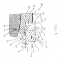
FIG. 2 is a cross sectional view of the support ofFIG. 1 mounted on a spherical bearing; -
FIG. 3 is a partial cross sectional view of the support ofFIG. 1 shown at an initial stage of installation in the spherical bearing; -
FIG. 4 is a partial cross sectional view of the support ofFIG. 1 shown at an intermediate stage of installation in the spherical bearing; and -
FIG. 5 is a partial cross sectional view of another support shown at an initial stage of installation in the spherical bearing. - Referring to
FIGS. 1 and2 , a support for a spherical bearing is generally designated by thenumeral 10. Thesupport 10 is defined by a substantiallyannular ring 12 having an axial facingabutment surface 14 on one end thereof. Theannular ring 12 has an inside surface 16 that is sloped radially outward toward theabutment surface 14. Thesupport 10 has alocking mechanism 18, such a threadedarea 18A on an outercircumferential surface 20 of the support. In one embodiment, the threadedarea 18A is a male screw thread. Thesupport 10 is operable to be secured substantially between axial ends of aspherical bearing 22 as described below. Thesupport 10 limits axial movement of an inner race defined by thespherical bearing 22, as detailed below. In addition, locating the threadedarea 18A on the outercircumferential surface 20 enables thesupport 10 to acquire a fatigue resistant, compressed state when installed in the spherical bearing and body, as described below. While thelocking mechanism 18 is described as being the threadedarea 18A, the present invention is not limited in this regard as other locking mechanisms may be employed, including but not limited to bayonet fittings. - In the embodiment illustrated in
FIG. 2 , thesupport 10 is disposed in aspherical bearing 22. Thespherical bearing 22 is defined by aninner race 24, for example a ball, having a substantially sphericalouter surface 26. Thespherical bearing 22 includes anouter race 28 positioned around theinner race 24 and having a substantially spherical inner surface 30. Theouter race 28 has apocket 32 formed in anend 34 thereof. Thepocket 32 is defined by a conicalouter surface 36 and an axial facingshoulder 38. In the illustrated embodiment, thesupport 10 is threaded into abody 40 havinginternal threads 42 to secure thesupport 10 and thespherical bearing 22 in thebody 40. Thesupport 10 is removably positioned in thepocket 32 so that the threadedarea 18A of the support engages theinternal threads 42 of thebody 40. Theabutment surface 14 of theannular ring 12 seats on theshoulder 38 to secure theouter race 28 to thebody 40. The sloped inside surface 16 of theannular ring 12 engages the conicalouter surface 36. When thesupport 10 is installed in thebody 40, the support is compressed between theinternal threads 42, theshoulder 38 and the conicalouter surface 36, thereby imparting fatigue resistance to the support, the outer surface and the internal threads. In addition, theabutment surface 14, the sloped inside surface 16 and the threadedarea 18 are in a fatigue resistant compressed state when the support is installed in thepocket 32. - The
outer race 28 has afirst end 44 defining a first opening 15A having first radius R1 and asecond end 46 defining a larger second opening 15B having a second radius R2. Theinner race 24 has a maximum radius R3 that is greater than the first radius R1 and the second radius R2. The second opening 15B is sized to receive theinner race 24 by temporarily expanding the second opening during assembly. Thefirst end 44 has a thickness T1 and thesecond end 46 has a thickness T2 that is less than the thickness T1. Thesupport 10 is disposed in thepocket 32 located proximate the second end. Although thesupport 10 is shown and described as being positioned in thepocket 32 located proximate the second end, the present invention is not limited in this regard as another support can be employed in a pocket located proximate the first end. - As illustrated in
FIG. 2 , theouter race 28 has a first width W1 and theinner race 24 has a second width W2. The second width W2 is greater that the first width W1. Thesupport 10 has an axial width W3 that is sized so that the support is positioned in thepocket 32, inboard of opposing ends of the axial ends of theinner race 24. The axial width W3 of thesupport 10 is about 10 to 20 percent of the width W2 of theinner race 24. In one embodiment asecond surface 48 of thesupport 10 opposite theabutment surface 14 is substantially coplanar with thesecond end 46 of theouter race 28. - As illustrated in
FIGS. 1 and2 the inside surface 16 of theannular ring 12 has a minimum inside diameter D1 at afirst point 50 located a distance of about 70 to 85 percent of the width W3 from theabutment surface 14. Theannular ring 12 has a second diameter D2 at asecond point 52 which is coplanar with theabutment surface 14. The diameter D2 is greater than the diameter D1. The inside surface 16 is sloped radially outward from thepoint 50 topoint 52 at an angle A of about 8 degrees relative to a longitudinal reference line L. The conicalouter surface 36 of thepocket 32 is sloped radially inward from athird point 54 defined by the intersection of the conical surface and theshoulder 38 to a fourth point 56 located at a distal edge of the conical surface. Theconical surface 36 slopes radially inward from thethird point 54 to the fourth point 56 by an angle B of about 8 degrees relative to the longitudinal reference line L1. While the angle A and the angle B are shown and described as being about 8 degrees, the present invention is not limited in this regard as angles A and B may have other magnitudes, including but not limited to the angle A being greater than the angle B; the angle A being from about zero to about 20 degrees and the angle B being from about zero to about 20 degrees; and the angle A being from about six to about 10 degrees and the angle B being from about six to about 10 degrees. - As illustrated in
FIGS. 1 and2 alip 60 extends axially from theannular ring 12 at thepoint 50 and is curved radially outward to form an annular channel 62 for receiving anannular seal 63. Oneend 64 of theseal 63 is seated in the channel 62 and anopposing end 66 of the seal is seated in a groove 68 formed in theinner race 24. Theseal 63 prevents debris from entering an area between the sphericalouter surface 26 and the spherical inner surface 30. In one embodiment, another seal 70 is located proximate thefirst end 44 and extends between theouter race 28 and theinner race 24. The engagement between thethreads 42 and the threadedarea 18; and the engagement between the conicalouter surface 36 and the sloped inside surface 16 sealingly prevents debris from entering thepocket 32, between theouter race 28 and thebody 40; and/or into an area adjacent theabutment surface 38. - As illustrated in
FIG. 1 , theannular ring 12 includes a plurality of axial bores 72 extending partially into the annular ring. The bores 72 are configured to receive a tool (not shown) for applying torque to theannular ring 12 during assembly and disassembly. - The
support 110 and bearing 122 illustrated inFIG. 5 are similar to thesupport 10 and bearing 22 shown inFIGS. 1-4 . Accordingly, similar elements are designated with similar element numbers preceded by the numeral 1. Thesupport 110 is illustrated having an internal threaded area 118A and a conicalouter surface 116. Theouter race 128 defines apocket 132 with an outwardly facing male threadedarea 142. Thebody 140 defines an inwardly facingconical surface 136. The conicalouter surface 116 defines an angle A relative to a reference line L. The inwardly facingconical surface 136 defines an angle B relative to a reference line L1. The angle A is about 8 degrees and about equal to the angle B. In one embodiment, the angle A is greater than the angle B before thesupport 110 is installed in thepocket 132. Thesupport 110 is installed into thepocket 132 similar to that described above for thesupport 10. - In one embodiment, the
support 10 is manufactured from a material different from that which theinner race 24 and/or theouter race 28 are manufactured. In one embodiment, thesupport 10 is manufactured from a material suitable for dampening vibrations transmitted between theinner race 24 and theouter race 28. - During assembly, the
annular ring 12 is threaded into thebody 40 causing the annular ring to move into thepocket 32 in the general direction indicated by the arrow F. As theannular ring 12 moves into thepocket 32, the inside surface 16 slidingly engages the conicalouter surface 36 until theabutment surface 14 engages theshoulder 38. Theannular ring 12 generates a radially directed force as indicated by the arrows H which limits outward radial movement of thesecond end 46 of theouter race 28. For example, when an axial load is applied to theinner race 24 in the general direction of the arrow K, theinner race 24 tends to urge thesecond end 46 of theouter race 28 outward in the general direction indicated by the arrow R. Thus theannular ring 12 is wedged into thepocket 32 to limit axial movement of theinner race 24 relative to theouter race 28. In addition, theannular ring 12 limits outward radial movement of thesecond end 46 of theouter race 28. The wedging of theannular ring 12 into thepocket 32 compresses the annular ring, theshoulder 38 and the conicalouter surface 36 for resistance to fatigue. The wedging of theannular ring 12 into the pocket causes theabutment surface 14, the sloped inside surface 16 and the threadedarea 18A to acquire a fatigue resistant compressed state when the support is installed in thepocket 32. Thus thesupport 10 is resistant to fatigue failure caused cyclic stresses imparted on the spherical bearing during operation. In addition, the wedging of thesupport 10 into thepocket 32 prevents thethreads 42 and the threadedarea 18 from inadvertently unscrewing from one another, thereby establishing a self locking configuration of the support in the pocket. In one embodiment, the wedging of thesupport 10 into the pocket causes theouter race 28 to be cold formed around theinner race 24. In one embodiment, adjustment of thesupport 10 in thepocket 32 affects the break-away torque required to cause movement between theinner race 24 and theouter race 28. For example, the magnitude of the break-away torque increases as thesupport 10 is screwed or otherwise forced into thepocket 32. - As illustrated in
FIG. 3 the angle A is greater than the angle B when thesupport 10 is in an initial stage of installation (FIG. 3 ). When in the initial stage of installation, aleading edge 16A of the inside surface 16 engages a leading edge 36A of the conicalouter surface 36. In an intermediate stage of installation (FIG. 4 ), thesupport 10 is threaded partially into thepocket 32. In the intermediate stage, the inside surface 16 engages the conicalouter surface 36 and theleading edge 16A is positioned between thesecond end 46 of theouter race 28 and the axial facingshoulder 38. During installation of thesupport 10 into thepocket 32 of theouter race 28 the support is wedged between theouter race 28 and thebody 40. During installation of thesupport 10 into thepocket 32, theinside surface 16A of the support and/or the conicalouter surface 36 of theouter race 28 conform such that the angle A and the angle B are substantially equal. - Although this invention has been shown and described with respect to the detailed embodiments thereof, it will be understood by those of skill in the art that various changes may be made and equivalents may be substituted for elements thereof without departing from the scope of the invention. In addition, modifications may be made to adapt a particular situation or material to the teachings of the invention without departing from the essential scope thereof. Therefore, it is intended that the invention not be limited to the particular embodiments disclosed in the above detailed description, but that the invention will include all embodiments falling within the scope of the appended claims.
Claims (13)
- A spherical bearing (22) comprising:a body (40);an inner race (24) having a substantially spherical outer surface (26);an outer race (28) positioned around the inner race (24) such that the outer race (28) has a first width (W1) and the inner race (24) has a second width (W2), the second width (W2) being greater than the first width (W1), the outer race (28) having a substantially spherical inner surface (30), a first end (44) and a second end (46) and defining a pocket (32) located proximate the second end (46) thereof, the pocket (32) defined by a conical outer surface (36) of the outer race (28), an axial facing shoulder (38) of the outer race (28) and internal threads (42) of the body (40), the first end (44) of the outer race (28) defining a first opening (15A) having a first radius (R1) and the second end (46) defining a larger second opening (15B) having a second radius (R2);a support (10) removably disposed in the pocket (32) and being positioned between axial ends of the spherical bearing (22), the support (10) being a substantially annular ring (12) defining an axial facing abutment surface (14) and an inside surface (16) being sloped radially outward toward the abutment surface (14) by about six to about ten degrees relative to a central axis of the annular ring (12), the annular ring (12) defining an outer circumferential surface (20) having a locking mechanism (18) thereon being removably engaged with the internal threads (42) of the body (40) to secure the annular ring (12) and the spherical bearing (22) to the body (40);the abutment surface (14) engaging the axial facing shoulder (38), and the inside surface (16) engaging the conical outer surface (36); andthe support is compressed between the internal threads (42), the shoulder (38) and the outer conical surface (36), and the support (10) being operable to limit axial movement of the inner race (24) relative to the outer race (28), wherein the inside surface (16) is configured to impart a radially inward wedging force on the conical outer surface (36) to limit outward radial movement of the outer race (28),wherein adjustment of the support (10) in the pocket (32) affects a break away torque required to cause movement between the inner race (24) and the outer race (28).
- The spherical bearing (22) of claim 1, wherein the locking mechanism (18) comprises a threaded area (18A).
- The spherical bearing (22) of claim 1, wherein the inside surface (16) is sloped radially outward by about 8 degrees relative to the central axis of the annular ring (12).
- The spherical bearing (22) of claim 1, wherein, the annular ring (12) has an axial width (W3) of about 10 to 20 percent of an axial width (W2) of the inner race (24).
- The spherical bearing (22) of claim 1, wherein the annular ring (12) includes a lip (60) extending therefrom, the lip (60) being operable to receive a portion of a seal (63) therein.
- The spherical bearing (22) of claim 1, wherein when the support (10) is installed in the pocket (32); the support (10), the conical outer surface (36) and the axialfacing shoulder (38) are in a fatigue resistant compressed state.
- The spherical bearing (22) of claim 1, wherein:the inner race (24) has a maximum radius (R3) that is greater than the first radius (R1) and the second radius (R2); andthe second opening (15B) is sized to receive the inner race (24) by temporarily expanding the second opening (15B) during assembly.
- The spherical bearing (22) of claim 1, wherein the first end (44) has a first thickness (T1) and the second end (46) has a second thickness (T2) that is less than the first thickness (T1).
- The spherical bearing (22) of claim 1, wherein the support (10) is positioned inboard of the first end (44) and the second end (46) of the outer race (28).
- The spherical bearing (22) of claim 1, wherein a second surface (48) of the support (10) opposite the abutment surface (14) is substantially coplanar with the second end (46) of the outer race (28).
- The spherical bearing (22) of claim 1, wherein the support (10) includes a plurality of axial bores (72) extending partially therein for receiving a tool for applying torque to the support (10).
- The spherical bearing (22) of claim 1, wherein the inner race (24) has a third end and a fourth end and the support (10) is positioned inboard of the third and fourth ends of the inner race (24).
- A spherical bearing (122) comprising:a body (140);an inner race (24) having a substantially spherical outer surface (26);an outer race (128) positioned around the inner race (24) such that the outer race (128) has a first width (W1) and the inner race (24) has a second width (W2), the second width (W2) being greater than the first width (W1), the outer race (128) having a substantially spherical inner surface (30), a first end (44) and a second end (146) and defining a pocket (132) located proximate the second end (146) thereof, the pocket (132) defined by a conical inwardly facing surface (136) of the body (140), an axial facing shoulder (138) of the outer race (128) and an outwardly facing threaded area (142) of the outer race (128), the first end (44) of the outer race (128) defines a first opening (15A) having a first radius (R1) and the second end (146) defines a larger second opening (15B) having a second radius (R2);a support (110) removably disposed in the pocket (132) and being positioned between axial ends of the spherical bearing (122), the support (110) being a substantially annular ring (112) defining an axial facing abutment surface (114) and an outside surface (116) being sloped radially inward toward the abutment surface (114) by about six to about ten degrees relative to a central axis of the annular ring (112), the annular ring (112) defining an inner circumferential surface having a locking mechanism (118) thereon being removably engaged with the outwardly facing threaded area (142) of the outer race (128) to secure the annular ring (112) to the outer race (128);the abutment surface (114) engaging the axial facing shoulder (138), and the outside surface (116) engaging the conical outer surface (136) of the body (140); andthe support (110) is compressed between the shoulder (138), the conical inwardly facing surface (136) and the outwardly facing threaded area (142), the support (110) being operable to limit axial movement of the inner race (24) relative to the outer race (128), wherein the conical inwardly facing surface (136) is configured to impart a radially inward wedging force on the support (110) to limit outward radial movement of the outer race (128),wherein adjustment of the support (110) in the pocket (132) affects a break away torque required to cause movement between the inner race (24) and the outer race (128).
Applications Claiming Priority (1)
| Application Number | Priority Date | Filing Date | Title |
|---|---|---|---|
| PCT/EP2012/055484 WO2013143582A1 (en) | 2012-03-28 | 2012-03-28 | Support for a spherical bearing |
Publications (2)
| Publication Number | Publication Date |
|---|---|
| EP2831434A1 EP2831434A1 (en) | 2015-02-04 |
| EP2831434B1 true EP2831434B1 (en) | 2018-07-18 |
Family
ID=45937301
Family Applications (1)
| Application Number | Title | Priority Date | Filing Date |
|---|---|---|---|
| EP12713056.5A Active EP2831434B1 (en) | 2012-03-28 | 2012-03-28 | Spherical bearing comprising a support |
Country Status (2)
| Country | Link |
|---|---|
| EP (1) | EP2831434B1 (en) |
| WO (1) | WO2013143582A1 (en) |
Families Citing this family (6)
| Publication number | Priority date | Publication date | Assignee | Title |
|---|---|---|---|---|
| EP2905485B1 (en) * | 2014-02-07 | 2020-12-30 | Schaublin SA | Seal and anchor system for spherical bearings |
| US9371861B2 (en) | 2014-02-11 | 2016-06-21 | Roller Bearing Company Of America, Inc. | Swaged bearing assembly with a flange mounted thereon |
| US10393179B2 (en) | 2014-10-01 | 2019-08-27 | Schaublin Sa | Segmented outer ring for a bearing for mitigating torque degradation |
| DE102015211005A1 (en) * | 2015-06-16 | 2016-12-22 | Zf Friedrichshafen Ag | ball joint |
| DE202017101399U1 (en) * | 2017-03-10 | 2017-03-30 | HÜBNER GmbH & Co. KG | Spherical bearing as a connection between two vehicles or vehicle parts |
| FR3094048B1 (en) | 2019-03-18 | 2021-04-23 | Skf Aerospace France | Connecting element, and method of manufacturing a ring for such a connecting element |
Citations (2)
| Publication number | Priority date | Publication date | Assignee | Title |
|---|---|---|---|---|
| FR2796110A1 (en) * | 1999-07-09 | 2001-01-12 | Sarma | Swivel ball joint consists of internal and external ring carrying clamping ring on its radial external surface and at point of swaging |
| EP1114942A2 (en) * | 2000-01-05 | 2001-07-11 | Minebea Co., Ltd. | Bearing mounting technique |
Family Cites Families (4)
| Publication number | Priority date | Publication date | Assignee | Title |
|---|---|---|---|---|
| DE4338916C1 (en) * | 1993-11-15 | 1995-05-04 | Trw Fahrwerksyst Gmbh & Co | Ball joint |
| US5824108A (en) * | 1997-03-26 | 1998-10-20 | Johnson & Johnson Professional, Inc. | Bipolar acetabular cup |
| DE19952427A1 (en) * | 1999-10-30 | 2001-05-03 | Audi Ag | Ball joint |
| KR100743577B1 (en) * | 2004-09-07 | 2007-07-30 | 주식회사 썬 프레인 코 | Structure for assembling boll joint of gas spring |
-
2012
- 2012-03-28 EP EP12713056.5A patent/EP2831434B1/en active Active
- 2012-03-28 WO PCT/EP2012/055484 patent/WO2013143582A1/en active Application Filing
Patent Citations (2)
| Publication number | Priority date | Publication date | Assignee | Title |
|---|---|---|---|---|
| FR2796110A1 (en) * | 1999-07-09 | 2001-01-12 | Sarma | Swivel ball joint consists of internal and external ring carrying clamping ring on its radial external surface and at point of swaging |
| EP1114942A2 (en) * | 2000-01-05 | 2001-07-11 | Minebea Co., Ltd. | Bearing mounting technique |
Also Published As
| Publication number | Publication date |
|---|---|
| EP2831434A1 (en) | 2015-02-04 |
| WO2013143582A1 (en) | 2013-10-03 |
Similar Documents
| Publication | Publication Date | Title |
|---|---|---|
| EP2831434B1 (en) | Spherical bearing comprising a support | |
| CA2565903C (en) | Taper lock bearing assembly | |
| US7597405B2 (en) | Wheel bearing joint unit | |
| US20130287519A1 (en) | Form locking connection with compensation of position errors | |
| EP2418392B1 (en) | Torque limiter | |
| EP2602123B1 (en) | An integrated hub-bearing assembly for the wheel of a motor vehicle | |
| CN106438932B (en) | Pulley device for a tension or winding roller | |
| CN107061467B (en) | Sealing nut | |
| US9702411B2 (en) | Bearing assembly with split outer ring having interference fit tabs and method of assembly of bearing | |
| US20120039556A1 (en) | ball bearing, a clutch bearing including such a bearing, and a motor vehicle fitted with such a bearing | |
| US20160236511A1 (en) | Extended length bearing cone system | |
| US8881877B2 (en) | Vibration damper | |
| US20080260494A1 (en) | Methods and apparatus for coupling gas turbine engine components | |
| EP3211254B1 (en) | Spherical bearing | |
| US8932011B2 (en) | Shaft assembly for a gas turbine engine | |
| US7309187B2 (en) | Releasable keyless bushing assembly | |
| EP3263933A1 (en) | Countersunk threaded bearing and method of installation | |
| KR101495390B1 (en) | Structural unit | |
| US5795119A (en) | Adjustable lock nut | |
| US20200072277A1 (en) | Anti pull-out collar for a ball joint | |
| EP2828539B1 (en) | Self-aligning miniature ball bearings with press-fit and self-clinching capabilities | |
| US11821466B2 (en) | Grooved nut | |
| US20240124270A1 (en) | Lifting Point | |
| US11371558B2 (en) | Roller bearing ring and dismounting procedure | |
| JP2010112506A (en) | Method and structure for coupling universal joint with shaft |
Legal Events
| Date | Code | Title | Description |
|---|---|---|---|
| REG | Reference to a national code |
Ref country code: DE Ref legal event code: R138 Ref document number: 202012013567 Country of ref document: DE Free format text: GERMAN DOCUMENT NUMBER IS 602012048582 |
|
| PUAI | Public reference made under article 153(3) epc to a published international application that has entered the european phase |
Free format text: ORIGINAL CODE: 0009012 |
|
| 17P | Request for examination filed |
Effective date: 20141024 |
|
| AK | Designated contracting states |
Kind code of ref document: A1 Designated state(s): AL AT BE BG CH CY CZ DE DK EE ES FI FR GB GR HR HU IE IS IT LI LT LU LV MC MK MT NL NO PL PT RO RS SE SI SK SM TR |
|
| AX | Request for extension of the european patent |
Extension state: BA ME |
|
| DAX | Request for extension of the european patent (deleted) | ||
| STAA | Information on the status of an ep patent application or granted ep patent |
Free format text: STATUS: EXAMINATION IS IN PROGRESS |
|
| 17Q | First examination report despatched |
Effective date: 20170412 |
|
| GRAP | Despatch of communication of intention to grant a patent |
Free format text: ORIGINAL CODE: EPIDOSNIGR1 |
|
| STAA | Information on the status of an ep patent application or granted ep patent |
Free format text: STATUS: GRANT OF PATENT IS INTENDED |
|
| INTG | Intention to grant announced |
Effective date: 20180328 |
|
| GRAS | Grant fee paid |
Free format text: ORIGINAL CODE: EPIDOSNIGR3 |
|
| GRAA | (expected) grant |
Free format text: ORIGINAL CODE: 0009210 |
|
| STAA | Information on the status of an ep patent application or granted ep patent |
Free format text: STATUS: THE PATENT HAS BEEN GRANTED |
|
| AK | Designated contracting states |
Kind code of ref document: B1 Designated state(s): AL AT BE BG CH CY CZ DE DK EE ES FI FR GB GR HR HU IE IS IT LI LT LU LV MC MK MT NL NO PL PT RO RS SE SI SK SM TR |
|
| REG | Reference to a national code |
Ref country code: GB Ref legal event code: FG4D |
|
| REG | Reference to a national code |
Ref country code: CH Ref legal event code: EP |
|
| REG | Reference to a national code |
Ref country code: IE Ref legal event code: FG4D |
|
| REG | Reference to a national code |
Ref country code: DE Ref legal event code: R096 Ref document number: 602012048582 Country of ref document: DE |
|
| REG | Reference to a national code |
Ref country code: AT Ref legal event code: REF Ref document number: 1019678 Country of ref document: AT Kind code of ref document: T Effective date: 20180815 |
|
| REG | Reference to a national code |
Ref country code: NL Ref legal event code: MP Effective date: 20180718 |
|
| REG | Reference to a national code |
Ref country code: LT Ref legal event code: MG4D |
|
| REG | Reference to a national code |
Ref country code: AT Ref legal event code: MK05 Ref document number: 1019678 Country of ref document: AT Kind code of ref document: T Effective date: 20180718 |
|
| PG25 | Lapsed in a contracting state [announced via postgrant information from national office to epo] |
Ref country code: NL Free format text: LAPSE BECAUSE OF FAILURE TO SUBMIT A TRANSLATION OF THE DESCRIPTION OR TO PAY THE FEE WITHIN THE PRESCRIBED TIME-LIMIT Effective date: 20180718 |
|
| PG25 | Lapsed in a contracting state [announced via postgrant information from national office to epo] |
Ref country code: FI Free format text: LAPSE BECAUSE OF FAILURE TO SUBMIT A TRANSLATION OF THE DESCRIPTION OR TO PAY THE FEE WITHIN THE PRESCRIBED TIME-LIMIT Effective date: 20180718 Ref country code: LT Free format text: LAPSE BECAUSE OF FAILURE TO SUBMIT A TRANSLATION OF THE DESCRIPTION OR TO PAY THE FEE WITHIN THE PRESCRIBED TIME-LIMIT Effective date: 20180718 Ref country code: PL Free format text: LAPSE BECAUSE OF FAILURE TO SUBMIT A TRANSLATION OF THE DESCRIPTION OR TO PAY THE FEE WITHIN THE PRESCRIBED TIME-LIMIT Effective date: 20180718 Ref country code: BG Free format text: LAPSE BECAUSE OF FAILURE TO SUBMIT A TRANSLATION OF THE DESCRIPTION OR TO PAY THE FEE WITHIN THE PRESCRIBED TIME-LIMIT Effective date: 20181018 Ref country code: AT Free format text: LAPSE BECAUSE OF FAILURE TO SUBMIT A TRANSLATION OF THE DESCRIPTION OR TO PAY THE FEE WITHIN THE PRESCRIBED TIME-LIMIT Effective date: 20180718 Ref country code: SE Free format text: LAPSE BECAUSE OF FAILURE TO SUBMIT A TRANSLATION OF THE DESCRIPTION OR TO PAY THE FEE WITHIN THE PRESCRIBED TIME-LIMIT Effective date: 20180718 Ref country code: RS Free format text: LAPSE BECAUSE OF FAILURE TO SUBMIT A TRANSLATION OF THE DESCRIPTION OR TO PAY THE FEE WITHIN THE PRESCRIBED TIME-LIMIT Effective date: 20180718 Ref country code: IS Free format text: LAPSE BECAUSE OF FAILURE TO SUBMIT A TRANSLATION OF THE DESCRIPTION OR TO PAY THE FEE WITHIN THE PRESCRIBED TIME-LIMIT Effective date: 20181118 Ref country code: GR Free format text: LAPSE BECAUSE OF FAILURE TO SUBMIT A TRANSLATION OF THE DESCRIPTION OR TO PAY THE FEE WITHIN THE PRESCRIBED TIME-LIMIT Effective date: 20181019 Ref country code: NO Free format text: LAPSE BECAUSE OF FAILURE TO SUBMIT A TRANSLATION OF THE DESCRIPTION OR TO PAY THE FEE WITHIN THE PRESCRIBED TIME-LIMIT Effective date: 20181018 |
|
| PG25 | Lapsed in a contracting state [announced via postgrant information from national office to epo] |
Ref country code: LV Free format text: LAPSE BECAUSE OF FAILURE TO SUBMIT A TRANSLATION OF THE DESCRIPTION OR TO PAY THE FEE WITHIN THE PRESCRIBED TIME-LIMIT Effective date: 20180718 Ref country code: HR Free format text: LAPSE BECAUSE OF FAILURE TO SUBMIT A TRANSLATION OF THE DESCRIPTION OR TO PAY THE FEE WITHIN THE PRESCRIBED TIME-LIMIT Effective date: 20180718 Ref country code: AL Free format text: LAPSE BECAUSE OF FAILURE TO SUBMIT A TRANSLATION OF THE DESCRIPTION OR TO PAY THE FEE WITHIN THE PRESCRIBED TIME-LIMIT Effective date: 20180718 |
|
| REG | Reference to a national code |
Ref country code: DE Ref legal event code: R097 Ref document number: 602012048582 Country of ref document: DE |
|
| PG25 | Lapsed in a contracting state [announced via postgrant information from national office to epo] |
Ref country code: ES Free format text: LAPSE BECAUSE OF FAILURE TO SUBMIT A TRANSLATION OF THE DESCRIPTION OR TO PAY THE FEE WITHIN THE PRESCRIBED TIME-LIMIT Effective date: 20180718 Ref country code: EE Free format text: LAPSE BECAUSE OF FAILURE TO SUBMIT A TRANSLATION OF THE DESCRIPTION OR TO PAY THE FEE WITHIN THE PRESCRIBED TIME-LIMIT Effective date: 20180718 Ref country code: IT Free format text: LAPSE BECAUSE OF FAILURE TO SUBMIT A TRANSLATION OF THE DESCRIPTION OR TO PAY THE FEE WITHIN THE PRESCRIBED TIME-LIMIT Effective date: 20180718 Ref country code: RO Free format text: LAPSE BECAUSE OF FAILURE TO SUBMIT A TRANSLATION OF THE DESCRIPTION OR TO PAY THE FEE WITHIN THE PRESCRIBED TIME-LIMIT Effective date: 20180718 Ref country code: CZ Free format text: LAPSE BECAUSE OF FAILURE TO SUBMIT A TRANSLATION OF THE DESCRIPTION OR TO PAY THE FEE WITHIN THE PRESCRIBED TIME-LIMIT Effective date: 20180718 |
|
| PLBE | No opposition filed within time limit |
Free format text: ORIGINAL CODE: 0009261 |
|
| STAA | Information on the status of an ep patent application or granted ep patent |
Free format text: STATUS: NO OPPOSITION FILED WITHIN TIME LIMIT |
|
| PG25 | Lapsed in a contracting state [announced via postgrant information from national office to epo] |
Ref country code: DK Free format text: LAPSE BECAUSE OF FAILURE TO SUBMIT A TRANSLATION OF THE DESCRIPTION OR TO PAY THE FEE WITHIN THE PRESCRIBED TIME-LIMIT Effective date: 20180718 Ref country code: SK Free format text: LAPSE BECAUSE OF FAILURE TO SUBMIT A TRANSLATION OF THE DESCRIPTION OR TO PAY THE FEE WITHIN THE PRESCRIBED TIME-LIMIT Effective date: 20180718 Ref country code: SM Free format text: LAPSE BECAUSE OF FAILURE TO SUBMIT A TRANSLATION OF THE DESCRIPTION OR TO PAY THE FEE WITHIN THE PRESCRIBED TIME-LIMIT Effective date: 20180718 |
|
| 26N | No opposition filed |
Effective date: 20190423 |
|
| PG25 | Lapsed in a contracting state [announced via postgrant information from national office to epo] |
Ref country code: SI Free format text: LAPSE BECAUSE OF FAILURE TO SUBMIT A TRANSLATION OF THE DESCRIPTION OR TO PAY THE FEE WITHIN THE PRESCRIBED TIME-LIMIT Effective date: 20180718 |
|
| PG25 | Lapsed in a contracting state [announced via postgrant information from national office to epo] |
Ref country code: MC Free format text: LAPSE BECAUSE OF FAILURE TO SUBMIT A TRANSLATION OF THE DESCRIPTION OR TO PAY THE FEE WITHIN THE PRESCRIBED TIME-LIMIT Effective date: 20180718 |
|
| GBPC | Gb: european patent ceased through non-payment of renewal fee |
Effective date: 20190328 |
|
| PG25 | Lapsed in a contracting state [announced via postgrant information from national office to epo] |
Ref country code: LU Free format text: LAPSE BECAUSE OF NON-PAYMENT OF DUE FEES Effective date: 20190328 |
|
| REG | Reference to a national code |
Ref country code: BE Ref legal event code: MM Effective date: 20190331 |
|
| PG25 | Lapsed in a contracting state [announced via postgrant information from national office to epo] |
Ref country code: IE Free format text: LAPSE BECAUSE OF NON-PAYMENT OF DUE FEES Effective date: 20190328 Ref country code: GB Free format text: LAPSE BECAUSE OF NON-PAYMENT OF DUE FEES Effective date: 20190328 |
|
| PG25 | Lapsed in a contracting state [announced via postgrant information from national office to epo] |
Ref country code: BE Free format text: LAPSE BECAUSE OF NON-PAYMENT OF DUE FEES Effective date: 20190331 |
|
| PG25 | Lapsed in a contracting state [announced via postgrant information from national office to epo] |
Ref country code: TR Free format text: LAPSE BECAUSE OF FAILURE TO SUBMIT A TRANSLATION OF THE DESCRIPTION OR TO PAY THE FEE WITHIN THE PRESCRIBED TIME-LIMIT Effective date: 20180718 |
|
| PG25 | Lapsed in a contracting state [announced via postgrant information from national office to epo] |
Ref country code: MT Free format text: LAPSE BECAUSE OF NON-PAYMENT OF DUE FEES Effective date: 20190328 Ref country code: PT Free format text: LAPSE BECAUSE OF FAILURE TO SUBMIT A TRANSLATION OF THE DESCRIPTION OR TO PAY THE FEE WITHIN THE PRESCRIBED TIME-LIMIT Effective date: 20181118 |
|
| PG25 | Lapsed in a contracting state [announced via postgrant information from national office to epo] |
Ref country code: CY Free format text: LAPSE BECAUSE OF FAILURE TO SUBMIT A TRANSLATION OF THE DESCRIPTION OR TO PAY THE FEE WITHIN THE PRESCRIBED TIME-LIMIT Effective date: 20180718 |
|
| PG25 | Lapsed in a contracting state [announced via postgrant information from national office to epo] |
Ref country code: HU Free format text: LAPSE BECAUSE OF FAILURE TO SUBMIT A TRANSLATION OF THE DESCRIPTION OR TO PAY THE FEE WITHIN THE PRESCRIBED TIME-LIMIT; INVALID AB INITIO Effective date: 20120328 |
|
| PG25 | Lapsed in a contracting state [announced via postgrant information from national office to epo] |
Ref country code: MK Free format text: LAPSE BECAUSE OF FAILURE TO SUBMIT A TRANSLATION OF THE DESCRIPTION OR TO PAY THE FEE WITHIN THE PRESCRIBED TIME-LIMIT Effective date: 20180718 |
|
| PGFP | Annual fee paid to national office [announced via postgrant information from national office to epo] |
Ref country code: FR Payment date: 20230324 Year of fee payment: 12 |
|
| PGFP | Annual fee paid to national office [announced via postgrant information from national office to epo] |
Ref country code: DE Payment date: 20230321 Year of fee payment: 12 |
|
| PGFP | Annual fee paid to national office [announced via postgrant information from national office to epo] |
Ref country code: CH Payment date: 20230401 Year of fee payment: 12 |