EP2831415B1 - Connecting device for a lightning protection system of a wind turbine - Google Patents
Connecting device for a lightning protection system of a wind turbine Download PDFInfo
- Publication number
- EP2831415B1 EP2831415B1 EP13736498.0A EP13736498A EP2831415B1 EP 2831415 B1 EP2831415 B1 EP 2831415B1 EP 13736498 A EP13736498 A EP 13736498A EP 2831415 B1 EP2831415 B1 EP 2831415B1
- Authority
- EP
- European Patent Office
- Prior art keywords
- rotor blade
- wind turbine
- transmission means
- transmitting device
- rotor
- Prior art date
- Legal status (The legal status is an assumption and is not a legal conclusion. Google has not performed a legal analysis and makes no representation as to the accuracy of the status listed.)
- Active
Links
- 230000005540 biological transmission Effects 0.000 description 78
- 239000004020 conductor Substances 0.000 description 37
- 230000006378 damage Effects 0.000 description 4
- 238000004519 manufacturing process Methods 0.000 description 2
- 230000007704 transition Effects 0.000 description 2
- 239000000853 adhesive Substances 0.000 description 1
- 230000001070 adhesive effect Effects 0.000 description 1
- 230000000254 damaging effect Effects 0.000 description 1
- 238000009795 derivation Methods 0.000 description 1
- 230000005684 electric field Effects 0.000 description 1
- 238000011835 investigation Methods 0.000 description 1
- 230000008018 melting Effects 0.000 description 1
- 238000002844 melting Methods 0.000 description 1
Images


Classifications
-
- H—ELECTRICITY
- H02—GENERATION; CONVERSION OR DISTRIBUTION OF ELECTRIC POWER
- H02G—INSTALLATION OF ELECTRIC CABLES OR LINES, OR OF COMBINED OPTICAL AND ELECTRIC CABLES OR LINES
- H02G13/00—Installations of lightning conductors; Fastening thereof to supporting structure
- H02G13/40—Connection to earth
-
- F—MECHANICAL ENGINEERING; LIGHTING; HEATING; WEAPONS; BLASTING
- F03—MACHINES OR ENGINES FOR LIQUIDS; WIND, SPRING, OR WEIGHT MOTORS; PRODUCING MECHANICAL POWER OR A REACTIVE PROPULSIVE THRUST, NOT OTHERWISE PROVIDED FOR
- F03D—WIND MOTORS
- F03D80/00—Details, components or accessories not provided for in groups F03D1/00 - F03D17/00
- F03D80/30—Lightning protection
-
- Y—GENERAL TAGGING OF NEW TECHNOLOGICAL DEVELOPMENTS; GENERAL TAGGING OF CROSS-SECTIONAL TECHNOLOGIES SPANNING OVER SEVERAL SECTIONS OF THE IPC; TECHNICAL SUBJECTS COVERED BY FORMER USPC CROSS-REFERENCE ART COLLECTIONS [XRACs] AND DIGESTS
- Y02—TECHNOLOGIES OR APPLICATIONS FOR MITIGATION OR ADAPTATION AGAINST CLIMATE CHANGE
- Y02E—REDUCTION OF GREENHOUSE GAS [GHG] EMISSIONS, RELATED TO ENERGY GENERATION, TRANSMISSION OR DISTRIBUTION
- Y02E10/00—Energy generation through renewable energy sources
- Y02E10/70—Wind energy
- Y02E10/72—Wind turbines with rotation axis in wind direction
Definitions
- the invention relates to a wind turbine with a connection device for connecting a first, permanently connected to a rotor blade of the wind turbine, lightning protection conductor to a second, fixedly arranged with the rotor hub of the wind turbine, lightning protection conductor.
- the rotor blade of the wind turbine is arranged via a blade bearing rotatable about its longitudinal axis on the rotor hub and can be adjusted to change the aerodynamic properties of the rotor.
- the rotation of the rotor blade is carried out by means of electric pitch drives.
- Wind turbines are equipped with a lightning protection system to protect the wind turbine from the damaging effects of a lightning strike.
- This system consists of a defined, low-impedance current path which leads past the components of the wind turbine to be protected. The current path is led by a lightning conductor arranged in the rotor blade, which leads from the highest point of the wind turbine, which corresponds to the tip of the rotor blade, through the wind turbine down to the ground.
- a transition must be created between the rotor blade and the rotor hub which allows a safe guidance of the lightning current without the movement of the rotor blade is limited.
- spark gap In known wind turbines, this transition is usually realized by a spark gap.
- the spark gap consists of two separate from an air gap electrodes. At a potential difference between the two electrodes, the air in the air gap is ionized by the resulting electric field, so that the air is conductive. The potential difference can then be compensated by a spark between the electrodes.
- WO2004 / 044419A1 discloses a wind turbine rotor having a rotor hub and a plurality of blades, each blade being connected by a pitch bearing to the rotor hub so that the blade is rotatable about its longitudinal axis with respect to the rotor hub.
- a lightning protection conductor is mounted, which is in electrical contact with a contact element and a fixedly connected to the rotor hub contact unit outside the sheet.
- connection device for connecting a first, permanently connectable to a rotor blade of a wind turbine, lightning protection conductor to a second, can be arranged firmly with a rotor hub of a wind turbine, lightning protection conductor, is arranged in the rotor blade.
- the connecting device comprises a first and a second transmission means, wherein the first transmission means rotatably disposed on the rotor blade and connected to a first arranged in the rotor blade lightning arrester and the second transmission means is connected to a second arranged on the rotor hub lightning conductor.
- the second transmission means is arranged such that it is rotatably movable about an axis of rotation parallel to a longitudinal axis of the rotor blade, but at the same time ensures that the two transmission means can not move in the radial or axial direction of the rotation axis to each other.
- the second transmission means is arranged in a holding device.
- the holding device is arranged by means of connecting elements on the rotor blade.
- the connecting element may be, for example, a screw, a rivet or an adhesive.
- the holding device may for example consist of a shaped sheet on which a pivot bearing for receiving the second transmission means is arranged. The sheet is thereby formed so that it comprises a receiving surface for the pivot bearing and at least one flange for attaching the holding device to the rotor blade.
- the second transmission means comprises a contact point and a fixing element for connecting a lightning protection conductor.
- the connection element may be formed, for example, as a conductive terminal or cable lug.
- the transmission means is advantageously provided with a fixing element for holding the lightning protection conductor. This prevents kinking and damage to the lightning conductor in the area of the connection element.
- the second transmission means may be formed rod-shaped and arranged in the rotary bearing, so that the longitudinal axis of the transmission means corresponds to the axis of rotation of the rotary bearing.
- the pivot bearing allows movement of the second transmission means about the axis of rotation of the pivot bearing, but prevents movement in the axial and radial directions of the axis of rotation. This ensures that the distance between the two transmission means, after it has been set correctly, is fixed in the radial and axial directions.
- connection device can be designed either as a spark gap or as a sliding contact. If the connecting device is designed as a spark gap, the contact point of the second transmission means may have a pointed shape, this has the advantage that the required flashover voltage for generating a spark is reduced.
- the spark gap is only suitable for the transmission of very high lightning currents, since an electrical connection is only available from a certain potential difference.
- the contact point of the second transmission means may also be designed as a grinding brush, which allows a permanent electrical connection to the first transmission means.
- the second transmission means is formed both with a spark gap and with a grinding brush.
- both low and high potential currents can be derived via the connection device.
- the contact point of the second transmission means is formed as a spark gap and the brush mounted removably attached to the second transmission means.
- the abrasive brush may, for example, be disposed on a support arm projecting in the radial direction from the rod-shaped transmission means. For space reasons, it is advantageous to combine the spark gap and the brush in the same connection device, but it could also be several connection devices, which have either a spark gap or a brush, are arranged in the rotor blade.
- the holding device and the first transmission means are arranged on the rotor blade, so that the central axes of the two transmission means in the mounted state are aligned.
- the first transmission means and the holding device and / or the second transmission means and the rotary bearing can be arranged in an electrically insulated manner relative to one another.
- the holding device can also be designed height adjustable so that the axial distance between the two transmission means can be varied. This can be done for example by placing washers between the rotor blade and the flange of the holding device, or by providing the flange with a thread and a threaded bolt.
- an inner ring of the pivot bearing with an internal thread and the second transmission means with an external thread Mistake By mutual rotation of the transmission means and the inner ring of the pivot bearing, the position of the transmission means in the pivot bearing and thus the distance of the spark gap can be varied. After the spark gap has been adjusted, the position of the transmission means can be locked with, for example, a lock nut.
- the height adjustment has the advantage that the distance between the transmission means of the spark gap can be adapted to the prevailing in different countries and at different locations weather conditions, so that a secure transmission of the lightning current is guaranteed.
- the connecting device is advantageously fastened at a distance to the blade bearing on the rotor blade.
- the lightning protection conductors are formed as cables.
- the first end of the lightning arrester arranged in the rotor blade is fastened to the tip of the rotor blade. Since the tip of the rotor blade is the highest point of the wind turbine, the flash will strike at this point.
- the second end of the lightning protection conductor arranged in the rotor blade is connected to the first transmission means, so that the lightning current is transmitted from the tip of the rotor blade to the connection device.
- the lightning conductor is fixedly mounted on the rotor blade. In the connection device, the lightning current is forwarded from the first transmission means via the spark gap to the second transmission means.
- the lightning current is forwarded by the second transmission means to a second lightning protection conductor arranged in the rotor hub.
- the arranged in the rotor hub lightning conductor is as far as possible firmly connected to the rotor hub. But to allow rotation of the rotor blade, the lightning conductor is guided in a loop from the rotor hub to the second transmission means and connected to the contact point and the fixing element of the transmission means.
- the Lightning protection conductors have a high mechanical torsional stiffness. If the lightning protection conductor arranged in the rotor hub were connected in a rotationally fixed manner to the connection device, this would twist during a rotation of the rotor blade and thus be damaged. Due to the rotatable arrangement of the second transmission means, the transmission means is tracked by the torsional rigidity of the lightning protection conductor connected thereto during a rotation of the rotor blade, so that the fixing element always points in the direction of the lightning protection conductor. The tracking prevents the lightning conductor from being twisted. Instead, the lightning protection conductor routed in the loop is subjected to a bend that is not critical for the lightning conductor.
- the first transmission means and the holding device are arranged on the rotor blade.
- the first transmission means and the holding device may also be arranged on the rotor hub, so that the arranged in the rotor blade lightning conductor is connected to the second rotatable transmission means and arranged in the rotor hub lightning conductor with the first transmission means. It is important that the lightning protection conductors connected to the first transmission means and connected to the second transmission means are arranged rotatably to each other.
- connection device can also be used for connecting lightning protection conductors between other components that can be rotated relative to one another, such as, for example, a machine house and a tower.
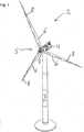
- FIG. 1 a wind turbine 2 is shown.
- the wind turbine 2 comprises a tower 3, a rotatably mounted on the tower 3 nacelle 4, arranged in the nacelle drive train 4 and arranged on the drive train and the drive train driving rotor 5.
- the rotor 5 includes a rotor hub 7 and at least one rotatable order a rotor axis 6 is the highest point of the wind turbine 2, the rotor blade 6 is provided with a lightning protection device for dissipating high lightning currents. The lightning current is thereby guided by the rotor blade 6 via the rotary joint between the rotor blade 6 and rotor hub 7 in the rotor hub 7 and then through the machine house 4 and the tower 3 to the ground.
- the rotor 5 with a connection device 1 for connecting a first, in the Rotor blade 6 arranged lightning protection conductor and a second, arranged in the rotor hub 7, lightning protection provided.
- FIG. 2 shows the connecting device 1 according to the invention.
- the connecting device 1 comprises a first transmission means 11a and a second transmission means 11b.
- the first transmission means 11a is arranged on the rotor blade 6 by means of connecting elements 24.
- the lightning protection conductor arranged in the rotor blade 6 is connected via a connection element 17 to the first transmission means 11a.
- the second transmission means 11b is rotatably arranged on a holding device 12 via a pivot bearing 19.
- the pivot bearing 19 allows rotation of the second transmission means 11 b about a rotation axis 13, but prevents movement of the second transmission means 11 b in the radial and axial direction of the rotation axis 13.
- the holding device 12 includes a receiving surface 22 for receiving the pivot bearing 19 and at least one flange 23rd for connecting the holding device to the rotor blade 6.
- the holding device 12 is connected to the rotor blade 6 by means of connecting elements 24 that can be arranged on the flange 23.
- connecting elements 24 can be arranged on the flange 23.
- the height of the holding device For adjusting the distance between the two transmission means 11a, 11b, the height of the holding device by placing washers between flange 23 and rotor blade 6.
- the flange 23 and the connecting means 24 may be threaded, so that the height of the holding device 12th can be adjusted by turning the connecting means 24.
- the second transmission means 11 b is provided with a connection element 17 and a fixing element 18 for connecting and fixing the lightning protection conductor connected to the rotor hub 7.
- the transmission means 11b is provided with a pointed end.
- the pivot bearing 19 is arranged with the aid of a releasably arranged on the receiving surface 22 retaining collar 26 on the holding device 12.
- FIG. 3 shows an abrasive brush 16 for transmitting lower potential currents from the rotor blade 6 to the rotor hub 7.
- the abrasive brush 16 may either be integrated in the transmission means 11 b or be formed as a tower.
- the attachment is attached to the formed as a spark gap second transmission means 11 b, so that the longitudinal axis of the grinding brush is parallel to the axis of rotation 13 of the second transmission means 11 b.
- the attachment consists of a holding arm 25, with a slot 21 for receiving the second transmission means 11b and a clamping screw 20 for securing the attachment on the second transmission means 11 b.
- FIG. 4 The slot 21 of the support arm 25 is thereby slid over the second transmission means 11 b and secured with the clamping screw 20, so that the longitudinal axis of the brush 16 parallel to the Rotary axis 13 of the second transmission means 11 b extends and the brush 16 forms a sliding contact 15 with the first transmission means 11 a.
- the length of the support arm 25 and the diameter of the first transmission means 11 a are selected such that the sliding contact 15 between the brush 16 and the first transmission means 11 a is maintained at a rotation of the second transmission means 11 b. Due to the combination of sliding contact 15 and spark gap 14, both low potential currents and high lightning currents can be transmitted from the connection device 1.
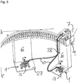
- connection device 1 In FIG. 5 the same connection device 1 is shown in the assembled state and in two different sheet positions.
- the connection device 1 is arranged on a surface 27 of the rotor blade 6 extending in the radial direction of the blade axis 8.
- the guided in a loop and connected to the rotor hub 7 lightning protection conductor 10 is connected to the connection element 17 of the second transmission means 11 b and fixed with the fixing member 18 on the second transmission means 11 b.
- the second transmission means 11 b Upon rotation of the rotor blade 6, the second transmission means 11 b by the Tordiersteiftechnik the lightning conductor 10th rotated about the axis of rotation 13, so that the transmission means 11 b is tracked and the connecting element 17 in each position of the rotor blade in the direction of attachment point 28 of the lightning conductor 10 to the rotor hub 7 shows.
- twisting of the lightning protection conductor 10 is substantially prevented.
- the guided in the loop part of the lightning conductor 10 is instead exposed to a harmless bend.
- connection device 15 sliding contact 2 wind turbine 16 brush 3 tower 17 connecting element 4 power house 18 fixing 5 rotor 19 pivot bearing 6 rotor blade 20 clamping screw 7 rotor hub 21 slot 8th blade axis 22 receiving surface 9 blade bearings 23 flange 10 Lightning Head 24 connecting element 11a First transmission means 25 holding arm 11b Second transmission means 26 retaining collar 12 holder 27 Radial surface of the rotor blade 13 axis of rotation 28 attachment point 14 radio link
Landscapes
- Engineering & Computer Science (AREA)
- Life Sciences & Earth Sciences (AREA)
- Sustainable Development (AREA)
- Sustainable Energy (AREA)
- Chemical & Material Sciences (AREA)
- Combustion & Propulsion (AREA)
- Mechanical Engineering (AREA)
- General Engineering & Computer Science (AREA)
- Wind Motors (AREA)
- Elimination Of Static Electricity (AREA)
Description
Die Erfindung betrifft eine Windturbine mit einer Anschlussvorrichtung zum Anschließen eines ersten, fest mit einem Rotorblatt der Windturbine verbundenen, Blitzschutzleiters an einen zweiten, fest mit der Rotornabe der Windturbine angeordneten, Blitzschutzleiter. Das Rotorblatt der Windturbine ist dabei über ein Blattlager drehbar um seine Längsachse an der Rotornabe angeordnet und kann zum Verändern der aerodynamischen Eigenschaften des Rotors verstellt werden. Die Drehung des Rotorblattes wird mittels elektrischer Pitchantriebe durchgeführt.The invention relates to a wind turbine with a connection device for connecting a first, permanently connected to a rotor blade of the wind turbine, lightning protection conductor to a second, fixedly arranged with the rotor hub of the wind turbine, lightning protection conductor. The rotor blade of the wind turbine is arranged via a blade bearing rotatable about its longitudinal axis on the rotor hub and can be adjusted to change the aerodynamic properties of the rotor. The rotation of the rotor blade is carried out by means of electric pitch drives.
Zum Schutz der Windturbine vor schädlichen Auswirkungen eines Blitzeinschlages werden Windturbinen mit einem Blitzschutzsystem ausgestattet. Dieses System besteht aus einen definierten, niederohmigen Strompfad der an den zu schützenden Komponenten der Windturbine vorbeiführt. Der Strompfad wird von einem im Rotorblatt angeordneten Blitzschutzleiter der von dem höchsten Punkt der Windturbine, was die Spitze des Rotorblatts entspricht, durch die Windturbine bis hinunter zum Erdboden führt. Da sich aber das Rotorblatt um seine Längsachse drehen kann, muss zwischen Rotorblatt und Rotornabe einen Übergang geschaffen werden der eine sichere Führung des Blitzstromes zulässt ohne dass die Bewegung des Rotorblattes eingeschränkt wird.Wind turbines are equipped with a lightning protection system to protect the wind turbine from the damaging effects of a lightning strike. This system consists of a defined, low-impedance current path which leads past the components of the wind turbine to be protected. The current path is led by a lightning conductor arranged in the rotor blade, which leads from the highest point of the wind turbine, which corresponds to the tip of the rotor blade, through the wind turbine down to the ground. However, since the rotor blade can rotate about its longitudinal axis, a transition must be created between the rotor blade and the rotor hub which allows a safe guidance of the lightning current without the movement of the rotor blade is limited.
Bei bekannten Windturbinen wird dieser Übergang meistens durch eine Funkenstrecke realisiert. Die Funkenstrecke besteht aus zwei von einem Luftspalt getrennten Elektroden. Bei einem Potentialunterschied zwischen den beiden Elektroden wird die in den Luftspalt befindliche Luft durch das entstehende elektrische Feld ionisiert, so dass die Luft leitfähig wird. Der Potentialunterschied kann danach durch einen Funken zwischen den Elektroden ausgeglichen werden.In known wind turbines, this transition is usually realized by a spark gap. The spark gap consists of two separate from an air gap electrodes. At a potential difference between the two electrodes, the air in the air gap is ionized by the resulting electric field, so that the air is conductive. The potential difference can then be compensated by a spark between the electrodes.
Um eine sichere Blitzstromübertragung gewährleisten zu können muss sichergestellt werden, dass ein korrekter Abstand zwischen den Elektroden eingehalten wird. Bekannte Windturbinen haben aber das Problem, dass die Fertigungstoleranzen so groß sind, so dass der Funkenabstand bei einer Drehung des Rotorblatts variiert und somit eine korrekte Funktion des Blitzschutzsystems nicht sichergestellt werden kann.To ensure a safe lightning current transmission, it must be ensured that a correct distance between the electrodes is maintained. However, known wind turbines have the problem that the manufacturing tolerances are so great that the spark gap varies with a rotation of the rotor blade and thus a correct function of the lightning protection system can not be ensured.
Es ist eine Aufgabe der Erfindung, ein verbessertes Blitzschutzsystem anzugeben, welches unter anderem die Nachteile des Stands der Technik vermeidet. Insbesondere soll dabei erreicht werden, dass ein korrekter Abstand zwischen den Elektroden zur jeder Zeit sichergestellt wird.It is an object of the invention to provide an improved lightning protection system which avoids, among other things, the disadvantages of the prior art. In particular, it should be ensured that a correct distance between the electrodes is ensured at all times.
Die Aufgabe wird erfindungsgemäß mit den Merkmalen des Hauptanspruchs 1 gelöst, indem eine Anschlussvorrichtung zum Anschließen eines ersten, fest mit einem Rotorblatt einer Windturbine verbindbaren, Blitzschutzleiters an einen zweiten, fest mit einer Rotornabe einer Windturbine anordenbaren, Blitzschutzleiters, in dem Rotorblatt angeordnet wird. Die Anschlussvorrichtung umfasst ein erstes und ein zweites Übertragungsmittel, wobei das erste Übertragungsmittel drehfest an dem Rotorblatt angeordnet und mit einem ersten in dem Rotorblatt angeordneten Blitzschutzleiter verbunden ist und das zweite Übertragungsmittel mit einem zweiten an der Rotornabe angeordneten Blitzschutzleiter verbunden ist. Das zweite Übertragungsmittel ist dabei derart angeordnet, so dass es drehbar um eine parallel zu einer Längsachse des Rotorblatts verlaufende Drehachse bewegbar ist, gleichzeitig aber sichergestellt wird, dass die beiden Übertragungsmittel sich nicht in radialer oder axialer Richtung der Drehachse zueinander bewegen können.The object is achieved with the features of the
Das zweite Übertragungsmittel wird dabei in einer Haltevorrichtung angeordnet. Die Haltevorrichtung wird mittels Verbindungselementen an dem Rotorblatt angeordnet. Das Verbindungselement kann zum Beispiel eine Schraube, eine Niete oder ein Klebstoff sein. Die Haltevorrichtung kann zum Beispiel aus einem geformten Blech bestehen, an dem ein Drehlager zum Aufnehmen des zweiten Übertragungsmittels angeordnet wird. Das Blech wird dabei so geformt, so dass es eine Aufnahmefläche für das Drehlager und mindestens einen Flansch zum Befestigen der Haltevorrichtung an dem Rotorblatt umfasst.The second transmission means is arranged in a holding device. The holding device is arranged by means of connecting elements on the rotor blade. The connecting element may be, for example, a screw, a rivet or an adhesive. The holding device may for example consist of a shaped sheet on which a pivot bearing for receiving the second transmission means is arranged. The sheet is thereby formed so that it comprises a receiving surface for the pivot bearing and at least one flange for attaching the holding device to the rotor blade.
Das zweite Übertragungsmittel umfasst einen Kontaktpunkt und ein Fixierelement zum Anschließen eines Blitzschutzleiters. Das Anschlusselement kann zum Beispiel als leitende Klemme oder Kabelschuh ausgebildet sein. Zum Stabilisieren des Blitzschutzleiters wird das Übertragungsmittel vorteilhafterweise mit einem Fixierelement zum Halten des Blitzschutzleiters versehen. Dies verhindert ein Knicken und eine Beschädigung des Blitzschutzleiters im Bereich des Anschlusselements. Das zweite Übertragungsmittel kann stabförmig ausgebildet werden und derart in dem Drehlager angeordnet sein, so dass die Längsachse des Übertragungsmittels mit der Drehachse des Drehlagers korrespondiert. Das Drehlager erlaubt eine Bewegung des zweiten Übertragungsmittels um die Drehachse des Drehlagers, verhindert jedoch eine Bewegung in axialer und radialer Richtung der Drehachse. Somit wird sichergestellt, dass der Abstand zwischen den beiden Übertragungsmitteln, nachdem dieser korrekt eingestellt wurde, in radialer und axialer Richtung fixiert wird.The second transmission means comprises a contact point and a fixing element for connecting a lightning protection conductor. The connection element may be formed, for example, as a conductive terminal or cable lug. To stabilize the lightning protection conductor, the transmission means is advantageously provided with a fixing element for holding the lightning protection conductor. This prevents kinking and damage to the lightning conductor in the area of the connection element. The second transmission means may be formed rod-shaped and arranged in the rotary bearing, so that the longitudinal axis of the transmission means corresponds to the axis of rotation of the rotary bearing. The pivot bearing allows movement of the second transmission means about the axis of rotation of the pivot bearing, but prevents movement in the axial and radial directions of the axis of rotation. This ensures that the distance between the two transmission means, after it has been set correctly, is fixed in the radial and axial directions.
Die Anschlussvorrichtung kann entweder als Funkenstrecke oder als Schleifkontakt ausgebildet sein. Falls die Anschlussvorrichtung als Funkenstrecke ausgebildet ist kann der Kontaktpunkt des zweiten Übertragungsmittels eine spitze Form aufweisen, dies hat den Vorteil, dass die benötigte Überschlagspannung zum Erzeugen eines Funkens verringert wird. Die Funkenstrecke eignet sich nur zur Übertragung von sehr hohen Blitzströmen, da eine elektrische Verbindung erst ab einem gewissen Potentialunterschied vorhanden ist.The connection device can be designed either as a spark gap or as a sliding contact. If the connecting device is designed as a spark gap, the contact point of the second transmission means may have a pointed shape, this has the advantage that the required flashover voltage for generating a spark is reduced. The spark gap is only suitable for the transmission of very high lightning currents, since an electrical connection is only available from a certain potential difference.
Um eine Ableitung von geringen Poteritialströmen zu ermöglichen kann der Kontaktpunkt des zweiten Übertragungsmittels auch als Schleifbürste, der eine permanente elektrische Verbindung mit dem ersten Übertragungsmittel zulässt, ausgebildet sein.In order to allow a derivation of low poteritialströmen the contact point of the second transmission means may also be designed as a grinding brush, which allows a permanent electrical connection to the first transmission means.
In einer besonders vorteilhaften Ausführung wird das zweite Übertragungsmittel sowohl mit einer Funkenstrecke als auch mit einer Schleifbürste ausgebildet. Bei dieser Ausführung kann sowohl geringe sowie hohe Potentialströme über die Anschlussvorrichtung abgeleitet werden. Bei dieser Ausführung wird der Kontaktpunkt des zweiten Übertragungsmittels als Funkenstrecke ausgebildet und die Schleifbürste lösbar befestigt an dem zweiten Übertragungsmittel angeordnet. Die Schleifbürste kann zum Beispiel auf einen, von dem stabförmigen Übertragungsmittel in radialer Richtung ausstehenden, Haltearm angeordnet sein. Aus Platzgründen ist es vorteilhaft die Funkenstrecke und die Schleifbürste in derselben Anschlussvorrichtung zu kombinieren, es könnten aber auch mehrere Anschlussvorrichtungen, die entweder eine Funkenstrecke oder eine Schleifbürste aufweisen, in dem Rotorblatt angeordnet werden.In a particularly advantageous embodiment, the second transmission means is formed both with a spark gap and with a grinding brush. In this embodiment, both low and high potential currents can be derived via the connection device. In this embodiment, the contact point of the second transmission means is formed as a spark gap and the brush mounted removably attached to the second transmission means. The abrasive brush may, for example, be disposed on a support arm projecting in the radial direction from the rod-shaped transmission means. For space reasons, it is advantageous to combine the spark gap and the brush in the same connection device, but it could also be several connection devices, which have either a spark gap or a brush, are arranged in the rotor blade.
Die Haltevorrichtung und das erste Übertragungsmittel werden derart an dem Rotorblatt angeordnet, so dass die Zentralachsen der beiden Übertragungsmittel im montierten Zustand miteinander fluchten. Um zu verhindern, dass der Blitzstrom einen anderen Weg als über die Funkenstrecke nimmt und zum Beispiel das Drehlager beschädigt, können das erste Übertragungsmittel und die Haltevorrichtung und/oder das zweite Übertragungsmittel und das Drehlager elektrisch isoliert zu einander angeordnet werden. Die Haltevorrichtung kann zusätzlich höhenverstellbar ausgelegt werden so dass der axiale Abstand zwischen den beiden Übertragungsmitteln variiert werden kann. Dies kann zum Beispiel durch Anordnung von Unterlegscheiben zwischen Rotorblatt und Flansch der Haltevorrichtung, oder durch versehen des Flansches mit einem Gewinde und einen Gewindebolzen geschehen. Es wäre auch denkbar einen Innenring des Drehlagers mit einem Innengewinde und das zweite Übertragungsmittel mit einem Außengewinde zu versehen. Durch gegenseitiges drehen des Übertragungsmittels und des Innenrings des Drehlagers, lässt sich die Position des Übertragungsmittels in dem Drehlager und somit der Abstand der Funkenstrecke variieren. Nachdem der Funkenabstand eingestellt worden ist, kann die Position des Übertragungsmittels mit zum Beispiel einer Kontermutter arretiert werden.The holding device and the first transmission means are arranged on the rotor blade, so that the central axes of the two transmission means in the mounted state are aligned. In order to prevent the lightning current from taking a different route than via the spark gap and, for example, damage the rotary bearing, the first transmission means and the holding device and / or the second transmission means and the rotary bearing can be arranged in an electrically insulated manner relative to one another. The holding device can also be designed height adjustable so that the axial distance between the two transmission means can be varied. This can be done for example by placing washers between the rotor blade and the flange of the holding device, or by providing the flange with a thread and a threaded bolt. It would also be conceivable an inner ring of the pivot bearing with an internal thread and the second transmission means with an external thread Mistake. By mutual rotation of the transmission means and the inner ring of the pivot bearing, the position of the transmission means in the pivot bearing and thus the distance of the spark gap can be varied. After the spark gap has been adjusted, the position of the transmission means can be locked with, for example, a lock nut.
Die Höhenverstellung hat den Vorteil, dass der Abstand zwischen den Übertragungsmitteln der Funkenstrecke an die in verschiedenen Ländern und an verschiedenen Standorten herrschenden Witterungsverhältnissen angepasst werden kann, so dass eine sichere Übertragung des Blitzstroms gewährleistet ist.The height adjustment has the advantage that the distance between the transmission means of the spark gap can be adapted to the prevailing in different countries and at different locations weather conditions, so that a secure transmission of the lightning current is guaranteed.
Die Anschlussvorrichtung wird vorteilhafterweise mit einem Abstand zu dem Blattlager auf dem Rotorblatt befestigt. Um den Blitzstrom zu der Anschlussvorrichtung zu leiten werden die Blitzschutzleiter als Kabel ausgebildet. Das erste Ende des im Rotorblatt angeordneten Blitzschutzleiters wird an die Spitze des Rotorblattes befestigt. Da die Spitze des Rotorblatts der höchste Punkt der Windturbine darstellt, wird der Blitz in diesem Punkt einschlagen. Das zweite Ende des im Rotorblatt angeordneten Blitzschutzleiters wird an dem ersten Übertragungsmittel angeschlossen, so dass der Blitzstrom von der Spitze des Rotorblattes an der Anschlussvorrichtung weitergeleitet wird. Der Blitzschutzleiter wird dabei fest an dem Rotorblatt montiert. In der Anschlussvorrichtung wird der Blitzstrom von dem ersten Übertragungsmittel über die Funkenstrecke an dem zweiten Übertragungsmittel weitergeleitet. Der Blitzstrom wird von dem zweiten Übertragungsmittel an einem zweiten, in der Rotornabe angeordneten, Blitzschutzleiter weitergeleitet. Der in der Rotornabe angeordnete Blitzschutzleiter wird soweit wie möglich fest mit der Rotornabe verbunden. Um aber eine Drehung des Rotorblattes zu ermöglichen, wird der Blitzschutzleiter in einer Schleife von der Rotornabe zu dem zweiten Übertragungsmittel geführt und an dem Kontaktpunkt und dem Fixierelement des Übertragungsmittels angeschlossen.The connecting device is advantageously fastened at a distance to the blade bearing on the rotor blade. To direct the lightning current to the connection device, the lightning protection conductors are formed as cables. The first end of the lightning arrester arranged in the rotor blade is fastened to the tip of the rotor blade. Since the tip of the rotor blade is the highest point of the wind turbine, the flash will strike at this point. The second end of the lightning protection conductor arranged in the rotor blade is connected to the first transmission means, so that the lightning current is transmitted from the tip of the rotor blade to the connection device. The lightning conductor is fixedly mounted on the rotor blade. In the connection device, the lightning current is forwarded from the first transmission means via the spark gap to the second transmission means. The lightning current is forwarded by the second transmission means to a second lightning protection conductor arranged in the rotor hub. The arranged in the rotor hub lightning conductor is as far as possible firmly connected to the rotor hub. But to allow rotation of the rotor blade, the lightning conductor is guided in a loop from the rotor hub to the second transmission means and connected to the contact point and the fixing element of the transmission means.
Damit die Blitzschutzleiter die sehr hohen Blitzströme überstehen können, müssen diese einen großen Durchmesser aufweisen. Dies hat aber zur Folge, dass die Blitzschutzleiter eine hohe mechanische Torsionssteifigkeit aufweisen. Wenn der in der Rotornabe angeordnete Blitzschutzleiter drehfest mit der Anschlussvorrichtung verbunden wäre, würde sich dieser bei einer Drehung des Rotorblattes tordieren und sich somit beschädigen. Durch die drehbare Anordnung des zweiten Übertragungsmittels, wird das Übertragungsmittel durch die Torsionssteifigkeit des damit verbundenen Blitzschutzleiters bei einer Drehung des Rotorblattes nachgeführt, so dass das Fixierelement immer in der Richtung des Blitzschutzleiters zeigt. Durch die Nachführung wird eine Tordierung des Blitzschutzleiters verhindert, stattdessen wird der in der Schleife geführte Blitzschutzleiter einer, für den Blitzschutzleiter unkritischen, Biegung ausgesetzt.In order for the lightning conductor to survive the very high lightning currents, they must have a large diameter. But this has the consequence that the Lightning protection conductors have a high mechanical torsional stiffness. If the lightning protection conductor arranged in the rotor hub were connected in a rotationally fixed manner to the connection device, this would twist during a rotation of the rotor blade and thus be damaged. Due to the rotatable arrangement of the second transmission means, the transmission means is tracked by the torsional rigidity of the lightning protection conductor connected thereto during a rotation of the rotor blade, so that the fixing element always points in the direction of the lightning protection conductor. The tracking prevents the lightning conductor from being twisted. Instead, the lightning protection conductor routed in the loop is subjected to a bend that is not critical for the lightning conductor.
Untersuchungen an den bekannten Blitzschutzvorrichtungen haben gezeigt, dass ein Teil des Blitzstromes, durch die lagernahe Anordnung der Funkenstrecke und der sich durch die hohen Fertigungstoleranzen ständig variierende Abstand der Übertragungsmittel der Funkenstrecke, durch das Blattlager geführt wird. Durch den durch das Lager geführten Blitzstrom kann es zu Ausschmelzungen an den Lagerteilen kommen. Diese Ausschmelzungen führen wiederum zu einem höheren Verschleiß in dem Lager und im schlimmsten Fall zur kompletten Zerstörung der mechanischen Teile. Durch die erfindungsgemäße, von dem Blattlager entfernten, Anordnung der Anschlussvorrichtung und den festen Abstand zwischen den Übertragungsmitteln, wird ein Stromfluss durch das Blattlager und somit eine Beschädigung des Blattlagers im Wesentlichen verhindert.Investigations on the known lightning protection devices have shown that part of the lightning current, due to the near-bearing arrangement of the spark gap and the constantly varying distance between the transmission means of the spark gap due to the high manufacturing tolerances, is guided through the blade bearing. Due to the lightning current passing through the bearing, it can lead to melting of the bearing parts. These recesses in turn lead to higher wear in the bearing and in the worst case to complete destruction of the mechanical parts. Due to the arrangement of the connecting device according to the invention, remote from the blade bearing and the fixed distance between the transmission means, a flow of current through the blade bearing and thus damage to the blade bearing is substantially prevented.
Bei der oben beschriebenen Ausführung werden das erste Übertragungsmittel und die Haltevorrichtung an dem Rotorblatt angeordnet. Selbstverständlich können das erste Übertragungsmittel und die Haltevorrichtung auch an der Rotornabe angeordnet sein, sodass der in dem Rotorblatt angeordnete Blitzschutzleiter mit dem zweiten drehbaren Übertragungsmittel und der in der Rotornabe angeordnete Blitzschutzleiter mit dem ersten Übertragungsmittel verbunden ist. Wichtig ist, dass der mit dem ersten Übertragungsmittel verbundene und der mit dem zweiten Übertragungsmittel verbundene Blitzschutzleiter verdrehbar zueinander angeordnet sind.In the embodiment described above, the first transmission means and the holding device are arranged on the rotor blade. Of course, the first transmission means and the holding device may also be arranged on the rotor hub, so that the arranged in the rotor blade lightning conductor is connected to the second rotatable transmission means and arranged in the rotor hub lightning conductor with the first transmission means. It is important that the lightning protection conductors connected to the first transmission means and connected to the second transmission means are arranged rotatably to each other.
Die Anschlussvorrichtung kann selbstverständlich auch zum Verbinden von Blitzschutzleitern zwischen anderen zueinander verdrehbaren Komponenten, wie zum Beispiel Maschinenhaus und Turm, verwendet werden.Of course, the connection device can also be used for connecting lightning protection conductors between other components that can be rotated relative to one another, such as, for example, a machine house and a tower.
Weitere Einzelheiten der Erfindung gehen aus den Zeichnungen anhand der Beschreibung hervor.Further details of the invention will become apparent from the drawings with reference to the description.
In den Zeichnungen zeigt
- Fig. 1
- eine Windturbine,
- Fig. 2
- eine als Funkenstrecke und Schleifkontakt ausgebildete Anschlussvorrichtung,
- Fig. 3
- die Anschlussvorrichtung als Funkenstrecke ausgebildet,
- Fig. 4
- einen als Schleifkontakt ausgebildeten Aufsatz für die Anschlussvorrichtung,
- Fig. 5
- die Anschlussvorrichtung in zwei verschiedenen Blattpositionen.
- Fig. 1
- a wind turbine,
- Fig. 2
- a connecting device designed as a spark gap and sliding contact,
- Fig. 3
- the connecting device is designed as a spark gap,
- Fig. 4
- a designed as a sliding contact attachment for the connection device,
- Fig. 5
- the connection device in two different leaf positions.
In
In
Die in den beschriebenen Ausführungsbeispielen offenbarten Merkmalskombinationen sollen nicht limitierend auf die Erfindung wirken.The feature combinations disclosed in the described exemplary embodiments are not intended to limit the invention.
Claims (9)
- Wind turbine (2) with a rotor blade (6) and a rotor hub (7), whereas the rotor blade (6) is rotatably mounted via a blade bearing (9) around a blade axis (8) on the rotor hub (7), as well as with a lightning protection system with a connecting device (1) arranged in the rotor blade (6) for connecting a first lightning arrester (10), firmly arranged on the rotor blade (6), arranged in the rotor blade (6), onto a second lightning arrester (10), firmly arranged on the rotor hub (7), characterized in thata. the connecting device (1) comprises a first transmitting device (11 a) firmly arranged on the rotor blade (6) and connected with the first lightning arrester (10) andb. a second transmitting device (11b) connected with the second lightning arrester (10),c. whereas the first transmitting device (11 a) and the second transmitting device (11 b) form a spark gap, andd. whereas the second transmitting device (11 b) is rotatably arranged in a way that the second transmitting device (11 b) is rotationally movable around a blade axis (8) parallel to the rotary axis (13), but the distance between the two transmitting devices (11 a, 11 b) in radial and axial direction of the rotary axis (13) remains always mainly constant.
- Wind turbine (2) according to claim 1, characterized in that the second transmitting device (11 b) is connected with the holding device (12) by means of a pivot bearing (19) and the holding device (12) is arranged on the rotor blade (6).
- Wind turbine (2) according to claim 1 or 2, characterized in that the distance between the transmitting devices (11 a, 11 b) is adjustable.
- Wind turbine (2) according to claim 3, characterized in that the distance can be adjusted by changing the position of the holding device (12) in relation to the rotor blade (6).
- Wind turbine (2) according to claim 3, characterized in that the distance can be adjusted by changing the position of the second transmitting device (11 b) in relation to the holding device (12).
- Wind turbine (2) according to one of the previous claims, characterized in that the second transmitting device (11 b) can be adjusted at a rotation of the rotor blade (6) due to the torsional stiffness of the lightning arrester (10) and therefore a twisting of the lightning arrester (10) arranged on the second transmitting device (11 b) is avoided.
- Wind turbine (2) according to one of the previous claims, characterized in that the transmitting devices (11a, 11b) are designed as spark gap (14) as well as sliding contact (15).
- Wind turbine (2) according to one of the previous claims, characterized in that the second transmitting device (11 b) is designed electrically isolated to the holding device (12).
- Wind turbine (2) according to one of the previous claims, characterized in that the holding device (12) and the first transmitting device (11a) are designed electrically isolated to each other.
Applications Claiming Priority (2)
| Application Number | Priority Date | Filing Date | Title |
|---|---|---|---|
| DE102012205208A DE102012205208B3 (en) | 2012-03-30 | 2012-03-30 | Connection device for a lightning protection system of a wind turbine |
| PCT/EP2013/056675 WO2013144279A2 (en) | 2012-03-30 | 2013-03-28 | Connecting device for a lightning protection system of a wind turbine |
Publications (2)
| Publication Number | Publication Date |
|---|---|
| EP2831415A2 EP2831415A2 (en) | 2015-02-04 |
| EP2831415B1 true EP2831415B1 (en) | 2016-05-25 |
Family
ID=48783191
Family Applications (1)
| Application Number | Title | Priority Date | Filing Date |
|---|---|---|---|
| EP13736498.0A Active EP2831415B1 (en) | 2012-03-30 | 2013-03-28 | Connecting device for a lightning protection system of a wind turbine |
Country Status (6)
| Country | Link |
|---|---|
| EP (1) | EP2831415B1 (en) |
| DE (1) | DE102012205208B3 (en) |
| DK (1) | DK2831415T3 (en) |
| ES (1) | ES2577111T3 (en) |
| PL (1) | PL2831415T3 (en) |
| WO (1) | WO2013144279A2 (en) |
Families Citing this family (3)
| Publication number | Priority date | Publication date | Assignee | Title |
|---|---|---|---|---|
| CN103527421B (en) * | 2013-11-08 | 2017-02-08 | 广东明阳风电产业集团有限公司 | Blade lightning protection device of offshore wind generating set |
| WO2016022150A1 (en) * | 2014-08-08 | 2016-02-11 | Schunk Graphite Technology, LLC | Electrostatic noise grounding system for use in a wind turbine and a rotor and wind turbine comprising the same |
| EP4074963A1 (en) * | 2021-04-14 | 2022-10-19 | Siemens Gamesa Renewable Energy A/S | Connector arrangement for a wind turbine down conductor, and wind turbine |
Family Cites Families (7)
| Publication number | Priority date | Publication date | Assignee | Title |
|---|---|---|---|---|
| DE10059923A1 (en) * | 2000-11-23 | 2002-06-06 | Huebner Elmasch Ag | Drehimpulsgeber |
| DK177270B1 (en) * | 2002-11-12 | 2012-09-10 | Lm Wind Power As | Lightning protection of pitch-regulated wind turbine wings |
| DE102004010104A1 (en) * | 2004-02-27 | 2005-09-29 | Repower Systems Ag | Wind turbine generator is protected against lightning strikes by a conductor system coupled to ground |
| DE102004022299A1 (en) * | 2004-05-04 | 2005-12-01 | Stemmann-Technik Gmbh | Wind turbine generator is protected against lightning strikes by a conductor system coupled to ground |
| DE102004012946B4 (en) * | 2004-03-17 | 2006-03-23 | Stemmann-Technik Gmbh | Wind turbine |
| NO327276B1 (en) * | 2007-11-08 | 2009-06-02 | Chapdrive As | Wind turbine with electric swivel |
| EP2234235B1 (en) * | 2009-03-23 | 2017-01-18 | Schunk Bahn- und Industrietechnik GmbH | Electricity transfer device, in particular lightning protection device |
-
2012
- 2012-03-30 DE DE102012205208A patent/DE102012205208B3/en not_active Expired - Fee Related
-
2013
- 2013-03-28 DK DK13736498.0T patent/DK2831415T3/en active
- 2013-03-28 PL PL13736498.0T patent/PL2831415T3/en unknown
- 2013-03-28 WO PCT/EP2013/056675 patent/WO2013144279A2/en active Application Filing
- 2013-03-28 ES ES13736498.0T patent/ES2577111T3/en active Active
- 2013-03-28 EP EP13736498.0A patent/EP2831415B1/en active Active
Non-Patent Citations (1)
| Title |
|---|
| None * |
Also Published As
| Publication number | Publication date |
|---|---|
| WO2013144279A2 (en) | 2013-10-03 |
| EP2831415A2 (en) | 2015-02-04 |
| DK2831415T3 (en) | 2016-07-04 |
| PL2831415T3 (en) | 2016-09-30 |
| DE102012205208B3 (en) | 2013-09-26 |
| ES2577111T3 (en) | 2016-07-13 |
| WO2013144279A3 (en) | 2013-11-28 |
Similar Documents
| Publication | Publication Date | Title |
|---|---|---|
| EP1282775B1 (en) | Wind power installation | |
| EP1568883B1 (en) | Lightning protection system for wind turbines | |
| DE102007052525B4 (en) | Device for dissipating a lightning in a wind turbine | |
| EP2619447B1 (en) | Blade connection of a rotor blade of a wind turbine | |
| DE60307312T2 (en) | LIGHTNING PROTECTION OF A NICK-CONTROLLED WIND TURBINE WING | |
| DE60004831T2 (en) | PROTECTION AGAINST ICE CREATION AND LIGHTNING FOR A WIND TURBINE BLADE | |
| EP1577551B1 (en) | Wind turbine | |
| DE4436197A1 (en) | Wind turbine electrical generation plant with lightning protection | |
| EP3317952B1 (en) | Carrier element, especially stator carier element and/or rotor carrier element, system of carrier elements, generator carrier, generator, generator carrier system, nacelle of a wind turbine, wind turbine and method for mounting a generator carrier system | |
| EP2831415B1 (en) | Connecting device for a lightning protection system of a wind turbine | |
| DE102008045939B4 (en) | Wind energy plant with lightning protection device | |
| EP2997256B1 (en) | Wind turbine and a lightning protection unit for a wind turbine | |
| EP2930356B1 (en) | Wind turbine rotor blade with a lightning protection system | |
| DE102004010104A1 (en) | Wind turbine generator is protected against lightning strikes by a conductor system coupled to ground | |
| EP1790852A1 (en) | Pivot bearing, particularly for wind power plants | |
| EP2935880B1 (en) | Method for arresting the electric energy of a lightning striking a wind turbine, and wind turbine | |
| WO2019038223A1 (en) | Wind-turbine rotor blade and lightning protection system for a wind-turbine rotor blade | |
| WO2019137881A1 (en) | Wind turbine rotor blade | |
| EP2234235B1 (en) | Electricity transfer device, in particular lightning protection device | |
| DE29522152U1 (en) | Lightning rod arrangement for a wind turbine blade | |
| DE4447942B4 (en) | Wind energy plant with lightning protection device | |
| EP2930354A1 (en) | Wind energy turbine rotor blade with a lightning protection conductor | |
| DE202010016941U1 (en) | Slip ring unit for a wind turbine | |
| DE102010045920A1 (en) | Overvoltage protection device for lightning protection of e.g. land-based wind-power plants, has interfaces forming electrical interruption during and/or after receiving separation signal, so that bridge is separated from cable end |
Legal Events
| Date | Code | Title | Description |
|---|---|---|---|
| PUAI | Public reference made under article 153(3) epc to a published international application that has entered the european phase |
Free format text: ORIGINAL CODE: 0009012 |
|
| 17P | Request for examination filed |
Effective date: 20141028 |
|
| AK | Designated contracting states |
Kind code of ref document: A2 Designated state(s): AL AT BE BG CH CY CZ DE DK EE ES FI FR GB GR HR HU IE IS IT LI LT LU LV MC MK MT NL NO PL PT RO RS SE SI SK SM TR |
|
| AX | Request for extension of the european patent |
Extension state: BA ME |
|
| DAX | Request for extension of the european patent (deleted) | ||
| GRAP | Despatch of communication of intention to grant a patent |
Free format text: ORIGINAL CODE: EPIDOSNIGR1 |
|
| INTG | Intention to grant announced |
Effective date: 20151119 |
|
| REG | Reference to a national code |
Ref country code: DE Ref legal event code: R079 Ref document number: 502013003198 Country of ref document: DE Free format text: PREVIOUS MAIN CLASS: F03D0011000000 Ipc: F03D0080000000 |
|
| GRAP | Despatch of communication of intention to grant a patent |
Free format text: ORIGINAL CODE: EPIDOSNIGR1 |
|
| RIC1 | Information provided on ipc code assigned before grant |
Ipc: H02G 13/00 20060101ALI20160225BHEP Ipc: F03D 80/00 20160101AFI20160225BHEP |
|
| INTG | Intention to grant announced |
Effective date: 20160309 |
|
| GRAS | Grant fee paid |
Free format text: ORIGINAL CODE: EPIDOSNIGR3 |
|
| GRAA | (expected) grant |
Free format text: ORIGINAL CODE: 0009210 |
|
| AK | Designated contracting states |
Kind code of ref document: B1 Designated state(s): AL AT BE BG CH CY CZ DE DK EE ES FI FR GB GR HR HU IE IS IT LI LT LU LV MC MK MT NL NO PL PT RO RS SE SI SK SM TR |
|
| REG | Reference to a national code |
Ref country code: GB Ref legal event code: FG4D Free format text: NOT ENGLISH |
|
| REG | Reference to a national code |
Ref country code: CH Ref legal event code: EP |
|
| REG | Reference to a national code |
Ref country code: IE Ref legal event code: FG4D Free format text: LANGUAGE OF EP DOCUMENT: GERMAN Ref country code: AT Ref legal event code: REF Ref document number: 802554 Country of ref document: AT Kind code of ref document: T Effective date: 20160615 |
|
| REG | Reference to a national code |
Ref country code: DK Ref legal event code: T3 Effective date: 20160624 |
|
| REG | Reference to a national code |
Ref country code: DE Ref legal event code: R096 Ref document number: 502013003198 Country of ref document: DE |
|
| REG | Reference to a national code |
Ref country code: ES Ref legal event code: FG2A Ref document number: 2577111 Country of ref document: ES Kind code of ref document: T3 Effective date: 20160713 |
|
| REG | Reference to a national code |
Ref country code: DE Ref legal event code: R082 Ref document number: 502013003198 Country of ref document: DE Ref country code: DE Ref legal event code: R081 Ref document number: 502013003198 Country of ref document: DE Owner name: AE ROTOR HOLDING B.V., NL Free format text: FORMER OWNER: SUZLON ENERGY GMBH, 18057 ROSTOCK, DE |
|
| REG | Reference to a national code |
Ref country code: LT Ref legal event code: MG4D |
|
| REG | Reference to a national code |
Ref country code: NL Ref legal event code: MP Effective date: 20160525 |
|
| RAP2 | Party data changed (patent owner data changed or rights of a patent transferred) |
Owner name: AE ROTOR HOLDING B.V. |
|
| REG | Reference to a national code |
Ref country code: ES Ref legal event code: PC2A Owner name: AE ROTOR HOLDING B.V. Effective date: 20161019 |
|
| PG25 | Lapsed in a contracting state [announced via postgrant information from national office to epo] |
Ref country code: NO Free format text: LAPSE BECAUSE OF FAILURE TO SUBMIT A TRANSLATION OF THE DESCRIPTION OR TO PAY THE FEE WITHIN THE PRESCRIBED TIME-LIMIT Effective date: 20160825 Ref country code: LT Free format text: LAPSE BECAUSE OF FAILURE TO SUBMIT A TRANSLATION OF THE DESCRIPTION OR TO PAY THE FEE WITHIN THE PRESCRIBED TIME-LIMIT Effective date: 20160525 Ref country code: FI Free format text: LAPSE BECAUSE OF FAILURE TO SUBMIT A TRANSLATION OF THE DESCRIPTION OR TO PAY THE FEE WITHIN THE PRESCRIBED TIME-LIMIT Effective date: 20160525 Ref country code: NL Free format text: LAPSE BECAUSE OF FAILURE TO SUBMIT A TRANSLATION OF THE DESCRIPTION OR TO PAY THE FEE WITHIN THE PRESCRIBED TIME-LIMIT Effective date: 20160525 |
|
| PG25 | Lapsed in a contracting state [announced via postgrant information from national office to epo] |
Ref country code: RS Free format text: LAPSE BECAUSE OF FAILURE TO SUBMIT A TRANSLATION OF THE DESCRIPTION OR TO PAY THE FEE WITHIN THE PRESCRIBED TIME-LIMIT Effective date: 20160525 Ref country code: LV Free format text: LAPSE BECAUSE OF FAILURE TO SUBMIT A TRANSLATION OF THE DESCRIPTION OR TO PAY THE FEE WITHIN THE PRESCRIBED TIME-LIMIT Effective date: 20160525 Ref country code: PT Free format text: LAPSE BECAUSE OF FAILURE TO SUBMIT A TRANSLATION OF THE DESCRIPTION OR TO PAY THE FEE WITHIN THE PRESCRIBED TIME-LIMIT Effective date: 20160926 Ref country code: GR Free format text: LAPSE BECAUSE OF FAILURE TO SUBMIT A TRANSLATION OF THE DESCRIPTION OR TO PAY THE FEE WITHIN THE PRESCRIBED TIME-LIMIT Effective date: 20160826 Ref country code: SE Free format text: LAPSE BECAUSE OF FAILURE TO SUBMIT A TRANSLATION OF THE DESCRIPTION OR TO PAY THE FEE WITHIN THE PRESCRIBED TIME-LIMIT Effective date: 20160525 |
|
| PG25 | Lapsed in a contracting state [announced via postgrant information from national office to epo] |
Ref country code: IT Free format text: LAPSE BECAUSE OF FAILURE TO SUBMIT A TRANSLATION OF THE DESCRIPTION OR TO PAY THE FEE WITHIN THE PRESCRIBED TIME-LIMIT Effective date: 20160525 |
|
| PG25 | Lapsed in a contracting state [announced via postgrant information from national office to epo] |
Ref country code: EE Free format text: LAPSE BECAUSE OF FAILURE TO SUBMIT A TRANSLATION OF THE DESCRIPTION OR TO PAY THE FEE WITHIN THE PRESCRIBED TIME-LIMIT Effective date: 20160525 Ref country code: CZ Free format text: LAPSE BECAUSE OF FAILURE TO SUBMIT A TRANSLATION OF THE DESCRIPTION OR TO PAY THE FEE WITHIN THE PRESCRIBED TIME-LIMIT Effective date: 20160525 Ref country code: RO Free format text: LAPSE BECAUSE OF FAILURE TO SUBMIT A TRANSLATION OF THE DESCRIPTION OR TO PAY THE FEE WITHIN THE PRESCRIBED TIME-LIMIT Effective date: 20160525 Ref country code: SK Free format text: LAPSE BECAUSE OF FAILURE TO SUBMIT A TRANSLATION OF THE DESCRIPTION OR TO PAY THE FEE WITHIN THE PRESCRIBED TIME-LIMIT Effective date: 20160525 |
|
| PG25 | Lapsed in a contracting state [announced via postgrant information from national office to epo] |
Ref country code: SM Free format text: LAPSE BECAUSE OF FAILURE TO SUBMIT A TRANSLATION OF THE DESCRIPTION OR TO PAY THE FEE WITHIN THE PRESCRIBED TIME-LIMIT Effective date: 20160525 |
|
| REG | Reference to a national code |
Ref country code: DE Ref legal event code: R097 Ref document number: 502013003198 Country of ref document: DE |
|
| REG | Reference to a national code |
Ref country code: GB Ref legal event code: 732E Free format text: REGISTERED BETWEEN 20170209 AND 20170215 |
|
| REG | Reference to a national code |
Ref country code: FR Ref legal event code: PLFP Year of fee payment: 5 |
|
| PLBE | No opposition filed within time limit |
Free format text: ORIGINAL CODE: 0009261 |
|
| STAA | Information on the status of an ep patent application or granted ep patent |
Free format text: STATUS: NO OPPOSITION FILED WITHIN TIME LIMIT |
|
| 26N | No opposition filed |
Effective date: 20170228 |
|
| PG25 | Lapsed in a contracting state [announced via postgrant information from national office to epo] |
Ref country code: SI Free format text: LAPSE BECAUSE OF FAILURE TO SUBMIT A TRANSLATION OF THE DESCRIPTION OR TO PAY THE FEE WITHIN THE PRESCRIBED TIME-LIMIT Effective date: 20160525 |
|
| REG | Reference to a national code |
Ref country code: CH Ref legal event code: PL |
|
| PG25 | Lapsed in a contracting state [announced via postgrant information from national office to epo] |
Ref country code: MC Free format text: LAPSE BECAUSE OF FAILURE TO SUBMIT A TRANSLATION OF THE DESCRIPTION OR TO PAY THE FEE WITHIN THE PRESCRIBED TIME-LIMIT Effective date: 20160525 |
|
| REG | Reference to a national code |
Ref country code: IE Ref legal event code: MM4A |
|
| PG25 | Lapsed in a contracting state [announced via postgrant information from national office to epo] |
Ref country code: LU Free format text: LAPSE BECAUSE OF NON-PAYMENT OF DUE FEES Effective date: 20170328 |
|
| PG25 | Lapsed in a contracting state [announced via postgrant information from national office to epo] |
Ref country code: CH Free format text: LAPSE BECAUSE OF NON-PAYMENT OF DUE FEES Effective date: 20170331 Ref country code: IE Free format text: LAPSE BECAUSE OF NON-PAYMENT OF DUE FEES Effective date: 20170328 Ref country code: LI Free format text: LAPSE BECAUSE OF NON-PAYMENT OF DUE FEES Effective date: 20170331 |
|
| REG | Reference to a national code |
Ref country code: BE Ref legal event code: MM Effective date: 20170331 |
|
| REG | Reference to a national code |
Ref country code: FR Ref legal event code: PLFP Year of fee payment: 6 |
|
| PG25 | Lapsed in a contracting state [announced via postgrant information from national office to epo] |
Ref country code: BE Free format text: LAPSE BECAUSE OF NON-PAYMENT OF DUE FEES Effective date: 20170331 |
|
| PG25 | Lapsed in a contracting state [announced via postgrant information from national office to epo] |
Ref country code: MT Free format text: LAPSE BECAUSE OF FAILURE TO SUBMIT A TRANSLATION OF THE DESCRIPTION OR TO PAY THE FEE WITHIN THE PRESCRIBED TIME-LIMIT Effective date: 20160525 |
|
| PG25 | Lapsed in a contracting state [announced via postgrant information from national office to epo] |
Ref country code: AL Free format text: LAPSE BECAUSE OF FAILURE TO SUBMIT A TRANSLATION OF THE DESCRIPTION OR TO PAY THE FEE WITHIN THE PRESCRIBED TIME-LIMIT Effective date: 20160525 |
|
| REG | Reference to a national code |
Ref country code: AT Ref legal event code: MM01 Ref document number: 802554 Country of ref document: AT Kind code of ref document: T Effective date: 20180328 |
|
| PG25 | Lapsed in a contracting state [announced via postgrant information from national office to epo] |
Ref country code: HU Free format text: LAPSE BECAUSE OF FAILURE TO SUBMIT A TRANSLATION OF THE DESCRIPTION OR TO PAY THE FEE WITHIN THE PRESCRIBED TIME-LIMIT; INVALID AB INITIO Effective date: 20130328 |
|
| PG25 | Lapsed in a contracting state [announced via postgrant information from national office to epo] |
Ref country code: BG Free format text: LAPSE BECAUSE OF FAILURE TO SUBMIT A TRANSLATION OF THE DESCRIPTION OR TO PAY THE FEE WITHIN THE PRESCRIBED TIME-LIMIT Effective date: 20160525 |
|
| PG25 | Lapsed in a contracting state [announced via postgrant information from national office to epo] |
Ref country code: AT Free format text: LAPSE BECAUSE OF NON-PAYMENT OF DUE FEES Effective date: 20180328 Ref country code: CY Free format text: LAPSE BECAUSE OF FAILURE TO SUBMIT A TRANSLATION OF THE DESCRIPTION OR TO PAY THE FEE WITHIN THE PRESCRIBED TIME-LIMIT Effective date: 20160525 |
|
| PG25 | Lapsed in a contracting state [announced via postgrant information from national office to epo] |
Ref country code: MK Free format text: LAPSE BECAUSE OF FAILURE TO SUBMIT A TRANSLATION OF THE DESCRIPTION OR TO PAY THE FEE WITHIN THE PRESCRIBED TIME-LIMIT Effective date: 20160525 |
|
| PGFP | Annual fee paid to national office [announced via postgrant information from national office to epo] |
Ref country code: DK Payment date: 20200324 Year of fee payment: 8 Ref country code: PL Payment date: 20200306 Year of fee payment: 8 Ref country code: GB Payment date: 20200327 Year of fee payment: 8 |
|
| PG25 | Lapsed in a contracting state [announced via postgrant information from national office to epo] |
Ref country code: HR Free format text: LAPSE BECAUSE OF FAILURE TO SUBMIT A TRANSLATION OF THE DESCRIPTION OR TO PAY THE FEE WITHIN THE PRESCRIBED TIME-LIMIT Effective date: 20160525 |
|
| PGFP | Annual fee paid to national office [announced via postgrant information from national office to epo] |
Ref country code: FR Payment date: 20200326 Year of fee payment: 8 |
|
| PG25 | Lapsed in a contracting state [announced via postgrant information from national office to epo] |
Ref country code: IS Free format text: LAPSE BECAUSE OF FAILURE TO SUBMIT A TRANSLATION OF THE DESCRIPTION OR TO PAY THE FEE WITHIN THE PRESCRIBED TIME-LIMIT Effective date: 20160925 |
|
| PGFP | Annual fee paid to national office [announced via postgrant information from national office to epo] |
Ref country code: ES Payment date: 20200427 Year of fee payment: 8 |
|
| REG | Reference to a national code |
Ref country code: DK Ref legal event code: EBP Effective date: 20210331 |
|
| GBPC | Gb: european patent ceased through non-payment of renewal fee |
Effective date: 20210328 |
|
| PG25 | Lapsed in a contracting state [announced via postgrant information from national office to epo] |
Ref country code: FR Free format text: LAPSE BECAUSE OF NON-PAYMENT OF DUE FEES Effective date: 20210331 Ref country code: GB Free format text: LAPSE BECAUSE OF NON-PAYMENT OF DUE FEES Effective date: 20210328 |
|
| PG25 | Lapsed in a contracting state [announced via postgrant information from national office to epo] |
Ref country code: DK Free format text: LAPSE BECAUSE OF NON-PAYMENT OF DUE FEES Effective date: 20210331 |
|
| REG | Reference to a national code |
Ref country code: ES Ref legal event code: FD2A Effective date: 20220701 |
|
| PG25 | Lapsed in a contracting state [announced via postgrant information from national office to epo] |
Ref country code: ES Free format text: LAPSE BECAUSE OF NON-PAYMENT OF DUE FEES Effective date: 20210329 |
|
| PG25 | Lapsed in a contracting state [announced via postgrant information from national office to epo] |
Ref country code: PL Free format text: LAPSE BECAUSE OF NON-PAYMENT OF DUE FEES Effective date: 20210328 |
|
| REG | Reference to a national code |
Ref country code: DE Ref legal event code: R081 Ref document number: 502013003198 Country of ref document: DE Owner name: SUZLON ENERGY LTD, IN Free format text: FORMER OWNER: AE ROTOR HOLDING B.V., HENGELO, NL |
|
| P01 | Opt-out of the competence of the unified patent court (upc) registered |
Effective date: 20230525 |
|
| PGFP | Annual fee paid to national office [announced via postgrant information from national office to epo] |
Ref country code: DE Payment date: 20240328 Year of fee payment: 12 |
|
| PGFP | Annual fee paid to national office [announced via postgrant information from national office to epo] |
Ref country code: TR Payment date: 20240308 Year of fee payment: 12 |