EP2831202B1 - Process for removing nitrogen from fuel streams with caprolactamium ionic liquids - Google Patents
Process for removing nitrogen from fuel streams with caprolactamium ionic liquids Download PDFInfo
- Publication number
- EP2831202B1 EP2831202B1 EP13770286.6A EP13770286A EP2831202B1 EP 2831202 B1 EP2831202 B1 EP 2831202B1 EP 13770286 A EP13770286 A EP 13770286A EP 2831202 B1 EP2831202 B1 EP 2831202B1
- Authority
- EP
- European Patent Office
- Prior art keywords
- fuel
- ionic liquid
- caprolactamium ionic
- effluent
- stream
- Prior art date
- Legal status (The legal status is an assumption and is not a legal conclusion. Google has not performed a legal analysis and makes no representation as to the accuracy of the status listed.)
- Active
Links
- 239000002608 ionic liquid Substances 0.000 title claims description 161
- 239000000446 fuel Substances 0.000 title claims description 126
- 238000000034 method Methods 0.000 title claims description 49
- IJGRMHOSHXDMSA-UHFFFAOYSA-N Atomic nitrogen Chemical compound N#N IJGRMHOSHXDMSA-UHFFFAOYSA-N 0.000 title description 162
- 229910052757 nitrogen Inorganic materials 0.000 title description 81
- XLYOFNOQVPJJNP-UHFFFAOYSA-N water Substances O XLYOFNOQVPJJNP-UHFFFAOYSA-N 0.000 claims description 34
- 229910017464 nitrogen compound Inorganic materials 0.000 claims description 33
- 150000002830 nitrogen compounds Chemical class 0.000 claims description 33
- 150000002430 hydrocarbons Chemical class 0.000 claims description 30
- 229930195733 hydrocarbon Natural products 0.000 claims description 29
- 239000000203 mixture Substances 0.000 claims description 26
- 239000004215 Carbon black (E152) Substances 0.000 claims description 24
- 230000008929 regeneration Effects 0.000 claims description 23
- 238000011069 regeneration method Methods 0.000 claims description 23
- 239000002283 diesel fuel Substances 0.000 claims description 20
- JBKVHLHDHHXQEQ-UHFFFAOYSA-N epsilon-caprolactam Chemical compound O=C1CCCCCN1 JBKVHLHDHHXQEQ-UHFFFAOYSA-N 0.000 claims description 20
- 239000007789 gas Substances 0.000 claims description 17
- 239000002904 solvent Substances 0.000 claims description 15
- 238000005406 washing Methods 0.000 claims description 13
- 238000006243 chemical reaction Methods 0.000 claims description 8
- 238000004519 manufacturing process Methods 0.000 claims description 8
- 239000003921 oil Substances 0.000 description 20
- 239000012071 phase Substances 0.000 description 15
- 238000000605 extraction Methods 0.000 description 14
- 238000000926 separation method Methods 0.000 description 14
- NINIDFKCEFEMDL-UHFFFAOYSA-N Sulfur Chemical compound [S] NINIDFKCEFEMDL-UHFFFAOYSA-N 0.000 description 13
- 239000011593 sulfur Substances 0.000 description 13
- 229910052717 sulfur Inorganic materials 0.000 description 13
- 238000001035 drying Methods 0.000 description 10
- 239000007788 liquid Substances 0.000 description 8
- 238000002156 mixing Methods 0.000 description 6
- 238000004231 fluid catalytic cracking Methods 0.000 description 5
- 230000003068 static effect Effects 0.000 description 4
- 238000004517 catalytic hydrocracking Methods 0.000 description 3
- 150000001875 compounds Chemical class 0.000 description 3
- 238000000354 decomposition reaction Methods 0.000 description 3
- 150000002500 ions Chemical class 0.000 description 3
- 239000000463 material Substances 0.000 description 3
- 229910052751 metal Inorganic materials 0.000 description 3
- 239000002184 metal Substances 0.000 description 3
- 150000002739 metals Chemical class 0.000 description 3
- 238000005191 phase separation Methods 0.000 description 3
- 238000011084 recovery Methods 0.000 description 3
- 230000002829 reductive effect Effects 0.000 description 3
- 238000012546 transfer Methods 0.000 description 3
- 238000004458 analytical method Methods 0.000 description 2
- 238000009835 boiling Methods 0.000 description 2
- 238000012864 cross contamination Methods 0.000 description 2
- 238000004821 distillation Methods 0.000 description 2
- 230000001747 exhibiting effect Effects 0.000 description 2
- 239000003502 gasoline Substances 0.000 description 2
- 239000012535 impurity Substances 0.000 description 2
- 230000000670 limiting effect Effects 0.000 description 2
- 238000012545 processing Methods 0.000 description 2
- 238000004064 recycling Methods 0.000 description 2
- 150000003839 salts Chemical class 0.000 description 2
- ZOXJGFHDIHLPTG-UHFFFAOYSA-N Boron Chemical compound [B] ZOXJGFHDIHLPTG-UHFFFAOYSA-N 0.000 description 1
- UFHFLCQGNIYNRP-UHFFFAOYSA-N Hydrogen Chemical compound [H][H] UFHFLCQGNIYNRP-UHFFFAOYSA-N 0.000 description 1
- 229920002292 Nylon 6 Polymers 0.000 description 1
- VEZUQRBDRNJBJY-UHFFFAOYSA-N ON=C1CCCCC1 Chemical compound ON=C1CCCCC1 VEZUQRBDRNJBJY-UHFFFAOYSA-N 0.000 description 1
- 230000002411 adverse Effects 0.000 description 1
- 238000013019 agitation Methods 0.000 description 1
- 229910052782 aluminium Inorganic materials 0.000 description 1
- XAGFODPZIPBFFR-UHFFFAOYSA-N aluminium Chemical compound [Al] XAGFODPZIPBFFR-UHFFFAOYSA-N 0.000 description 1
- 150000001450 anions Chemical class 0.000 description 1
- 229910052787 antimony Inorganic materials 0.000 description 1
- WATWJIUSRGPENY-UHFFFAOYSA-N antimony atom Chemical compound [Sb] WATWJIUSRGPENY-UHFFFAOYSA-N 0.000 description 1
- 229910052785 arsenic Inorganic materials 0.000 description 1
- RQNWIZPPADIBDY-UHFFFAOYSA-N arsenic atom Chemical compound [As] RQNWIZPPADIBDY-UHFFFAOYSA-N 0.000 description 1
- 238000004380 ashing Methods 0.000 description 1
- 229910052796 boron Inorganic materials 0.000 description 1
- 239000003054 catalyst Substances 0.000 description 1
- 230000003197 catalytic effect Effects 0.000 description 1
- 238000009903 catalytic hydrogenation reaction Methods 0.000 description 1
- 125000002091 cationic group Chemical group 0.000 description 1
- 238000005119 centrifugation Methods 0.000 description 1
- 238000002038 chemiluminescence detection Methods 0.000 description 1
- 238000004939 coking Methods 0.000 description 1
- 238000002485 combustion reaction Methods 0.000 description 1
- 239000000356 contaminant Substances 0.000 description 1
- 230000009849 deactivation Effects 0.000 description 1
- 238000010908 decantation Methods 0.000 description 1
- 238000006477 desulfuration reaction Methods 0.000 description 1
- 230000023556 desulfurization Effects 0.000 description 1
- 238000010790 dilution Methods 0.000 description 1
- 239000012895 dilution Substances 0.000 description 1
- 239000003344 environmental pollutant Substances 0.000 description 1
- 238000002474 experimental method Methods 0.000 description 1
- 238000007701 flash-distillation Methods 0.000 description 1
- 239000012530 fluid Substances 0.000 description 1
- 238000005194 fractionation Methods 0.000 description 1
- 125000005842 heteroatom Chemical group 0.000 description 1
- BHEPBYXIRTUNPN-UHFFFAOYSA-N hydridophosphorus(.) (triplet) Chemical compound [PH] BHEPBYXIRTUNPN-UHFFFAOYSA-N 0.000 description 1
- 239000001257 hydrogen Substances 0.000 description 1
- 229910052739 hydrogen Inorganic materials 0.000 description 1
- QAOWNCQODCNURD-UHFFFAOYSA-M hydrogensulfate Chemical compound OS([O-])(=O)=O QAOWNCQODCNURD-UHFFFAOYSA-M 0.000 description 1
- 238000002354 inductively-coupled plasma atomic emission spectroscopy Methods 0.000 description 1
- 239000011261 inert gas Substances 0.000 description 1
- 238000011031 large-scale manufacturing process Methods 0.000 description 1
- 238000004811 liquid chromatography Methods 0.000 description 1
- 238000002844 melting Methods 0.000 description 1
- 230000008018 melting Effects 0.000 description 1
- -1 naphtha Substances 0.000 description 1
- 150000002898 organic sulfur compounds Chemical class 0.000 description 1
- 125000002524 organometallic group Chemical group 0.000 description 1
- 230000001590 oxidative effect Effects 0.000 description 1
- 238000012856 packing Methods 0.000 description 1
- 230000036961 partial effect Effects 0.000 description 1
- 239000003208 petroleum Substances 0.000 description 1
- 239000003209 petroleum derivative Substances 0.000 description 1
- 231100000719 pollutant Toxicity 0.000 description 1
- 229920000642 polymer Polymers 0.000 description 1
- 238000007670 refining Methods 0.000 description 1
- 238000002407 reforming Methods 0.000 description 1
- 229920006395 saturated elastomer Polymers 0.000 description 1
- 239000007787 solid Substances 0.000 description 1
- 238000003756 stirring Methods 0.000 description 1
- 239000000126 substance Substances 0.000 description 1
Images

Classifications
-
- C—CHEMISTRY; METALLURGY
- C10—PETROLEUM, GAS OR COKE INDUSTRIES; TECHNICAL GASES CONTAINING CARBON MONOXIDE; FUELS; LUBRICANTS; PEAT
- C10G—CRACKING HYDROCARBON OILS; PRODUCTION OF LIQUID HYDROCARBON MIXTURES, e.g. BY DESTRUCTIVE HYDROGENATION, OLIGOMERISATION, POLYMERISATION; RECOVERY OF HYDROCARBON OILS FROM OIL-SHALE, OIL-SAND, OR GASES; REFINING MIXTURES MAINLY CONSISTING OF HYDROCARBONS; REFORMING OF NAPHTHA; MINERAL WAXES
- C10G21/00—Refining of hydrocarbon oils, in the absence of hydrogen, by extraction with selective solvents
- C10G21/06—Refining of hydrocarbon oils, in the absence of hydrogen, by extraction with selective solvents characterised by the solvent used
- C10G21/12—Organic compounds only
- C10G21/27—Organic compounds not provided for in a single one of groups C10G21/14 - C10G21/26
-
- C—CHEMISTRY; METALLURGY
- C10—PETROLEUM, GAS OR COKE INDUSTRIES; TECHNICAL GASES CONTAINING CARBON MONOXIDE; FUELS; LUBRICANTS; PEAT
- C10G—CRACKING HYDROCARBON OILS; PRODUCTION OF LIQUID HYDROCARBON MIXTURES, e.g. BY DESTRUCTIVE HYDROGENATION, OLIGOMERISATION, POLYMERISATION; RECOVERY OF HYDROCARBON OILS FROM OIL-SHALE, OIL-SAND, OR GASES; REFINING MIXTURES MAINLY CONSISTING OF HYDROCARBONS; REFORMING OF NAPHTHA; MINERAL WAXES
- C10G21/00—Refining of hydrocarbon oils, in the absence of hydrogen, by extraction with selective solvents
- C10G21/28—Recovery of used solvent
-
- C—CHEMISTRY; METALLURGY
- C10—PETROLEUM, GAS OR COKE INDUSTRIES; TECHNICAL GASES CONTAINING CARBON MONOXIDE; FUELS; LUBRICANTS; PEAT
- C10G—CRACKING HYDROCARBON OILS; PRODUCTION OF LIQUID HYDROCARBON MIXTURES, e.g. BY DESTRUCTIVE HYDROGENATION, OLIGOMERISATION, POLYMERISATION; RECOVERY OF HYDROCARBON OILS FROM OIL-SHALE, OIL-SAND, OR GASES; REFINING MIXTURES MAINLY CONSISTING OF HYDROCARBONS; REFORMING OF NAPHTHA; MINERAL WAXES
- C10G31/00—Refining of hydrocarbon oils, in the absence of hydrogen, by methods not otherwise provided for
- C10G31/08—Refining of hydrocarbon oils, in the absence of hydrogen, by methods not otherwise provided for by treating with water
-
- C—CHEMISTRY; METALLURGY
- C10—PETROLEUM, GAS OR COKE INDUSTRIES; TECHNICAL GASES CONTAINING CARBON MONOXIDE; FUELS; LUBRICANTS; PEAT
- C10G—CRACKING HYDROCARBON OILS; PRODUCTION OF LIQUID HYDROCARBON MIXTURES, e.g. BY DESTRUCTIVE HYDROGENATION, OLIGOMERISATION, POLYMERISATION; RECOVERY OF HYDROCARBON OILS FROM OIL-SHALE, OIL-SAND, OR GASES; REFINING MIXTURES MAINLY CONSISTING OF HYDROCARBONS; REFORMING OF NAPHTHA; MINERAL WAXES
- C10G53/00—Treatment of hydrocarbon oils, in the absence of hydrogen, by two or more refining processes
- C10G53/02—Treatment of hydrocarbon oils, in the absence of hydrogen, by two or more refining processes plural serial stages only
- C10G53/04—Treatment of hydrocarbon oils, in the absence of hydrogen, by two or more refining processes plural serial stages only including at least one extraction step
- C10G53/06—Treatment of hydrocarbon oils, in the absence of hydrogen, by two or more refining processes plural serial stages only including at least one extraction step including only extraction steps, e.g. deasphalting by solvent treatment followed by extraction of aromatics
-
- C—CHEMISTRY; METALLURGY
- C10—PETROLEUM, GAS OR COKE INDUSTRIES; TECHNICAL GASES CONTAINING CARBON MONOXIDE; FUELS; LUBRICANTS; PEAT
- C10G—CRACKING HYDROCARBON OILS; PRODUCTION OF LIQUID HYDROCARBON MIXTURES, e.g. BY DESTRUCTIVE HYDROGENATION, OLIGOMERISATION, POLYMERISATION; RECOVERY OF HYDROCARBON OILS FROM OIL-SHALE, OIL-SAND, OR GASES; REFINING MIXTURES MAINLY CONSISTING OF HYDROCARBONS; REFORMING OF NAPHTHA; MINERAL WAXES
- C10G2300/00—Aspects relating to hydrocarbon processing covered by groups C10G1/00 - C10G99/00
- C10G2300/20—Characteristics of the feedstock or the products
- C10G2300/201—Impurities
- C10G2300/202—Heteroatoms content, i.e. S, N, O, P
Definitions
- This invention relates to processes for reducing the nitrogen content of hydrocarbonaceous liquid fuels like vacuum gas oils (VGO) and diesel fuels. More particularly, the invention relates to removing nitrogen contaminants from VGO and diesel fuels using an ionic liquid that is an intermediate in the manufacture of caprolactam.
- VGO vacuum gas oils
- ionic liquid that is an intermediate in the manufacture of caprolactam.
- VGO is a hydrocarbon fraction that may be converted into higher value hydrocarbon fractions such as diesel fuel, jet fuel, naphtha, gasoline, and other lower boiling fractions in refining processes such as hydrocracking and fluid catalytic cracking (FCC).
- FCC fluid catalytic cracking
- VGO feed streams having higher amounts of nitrogen are more difficult to convert.
- the degree of conversion, product yields, catalyst deactivation, and/or ability to meet product quality specifications may be adversely affected by the nitrogen content of the feed stream. It is known to reduce the nitrogen content of VGO by catalytic hydrogenation reactions such as in a hydrotreating process unit.
- Diesel fuel contains sulfur-containing molecules that are well known pollutants. Therefore, there is an ever increasing need to provide diesel fuels that have ultra low sulfur content.
- a typical way of removing sulfur from diesel fuel is by catalytic hydrodesulfurization (HDS). It is, however, becoming more difficult to catalytically hydrodesulfurize diesel fuels to the lower level of sulfur now required. Since nitrogen content interferes with the effective removal of sulfur, it is necessary to remove nitrogen prior to removing the sulfur.
- HDS catalytic hydrodesulfurization
- US 7,001,504 B2 discloses a process for the removal of organosulfur compounds from hydrocarbon materials which includes contacting an ionic liquid with a hydrocarbon material to extract sulfur containing compounds into the ionic liquid.
- US 7,553,406 B2 discloses a process for removing polarizable impurities from hydrocarbons and mixtures of hydrocarbons using ionic liquids as an extraction medium.
- US 7,553,406 B2 also discloses that different ionic liquids show different extractive properties for different polarizable compounds.
- VGO vacuum gas oil
- Caprolactamium is an intermediate in the manufacture of caprolactam which in turn is used in the production of engineering polymers such as polyamide 6. Since millions of tons of caprolactam are used per year, there are correspondingly large amounts of the caprolactamium ionic liquid that are produced. While this ionic liquid has been known for many years, it is shown here to be effective in treatment of fuels, such as diesel fuel and vacuum gas oil.
- the invention is a process for removing a nitrogen compound from a vacuum gas oil comprising contacting the vacuum gas oil with a VGO-immiscible caprolactamium ionic liquid to produce a vacuum gas oil and VGO-immiscible caprolactamium ionic liquid mixture, and separating the mixture to produce a vacuum gas oil effluent and a VGO-immiscible caprolactamium ionic liquid effluent comprising the nitrogen compound.
- the ionic liquid used in the present invention is shown in the formula below that shows its prior art use in the production of caprolactam.
- the invention is a process for removing a nitrogen compound from a diesel fuel comprising contacting the diesel fuel with a diesel-immiscible caprolactamium ionic liquid to produce a diesel and diesel-immiscible caprolactamium ionic liquid mixture, and separating the mixture to produce a diesel fuel effluent and a diesel-immiscible caprolactamium ionic liquid effluent comprising the nitrogen compound.
- the invention may be used to remove a nitrogen compound from a hydrocarbonaceous liquid fuel, more specifically a vacuum gas oil (VGO) hydrocarbon fraction or from diesel fuel through use of a caprolactamium ionic liquid.
- VGO vacuum gas oil
- vacuum gas oil VGO
- VGO phase VGO phase
- similar terms relating to vacuum gas oil as used herein are to be interpreted broadly to receive not only their ordinary meanings as used by those skilled in the art of producing and converting such hydrocarbon fractions, but also in a broad manner to account for the application of our processes to hydrocarbon fractions exhibiting VGO-like characteristics.
- the terms encompass straight run VGO as may be produced in a crude fractionation section of an oil refinery, as well as, VGO product cuts, fractions, or streams that may be produced, for example, by coker, deasphalting, and visbreaking processing units, or which may be produced by blending various hydrocarbons.
- VGO comprises petroleum hydrocarbon components boiling in the range of from 100° to 720°C.
- the VGO boils from 250° to 650°C and has a density in the range of from 0.87 to 0.95 g/cm 3 .
- the VGO boils from 95° to 580°C; and in a further embodiment, the VGO boils from 300° to 720°C.
- VGO may contain from 100 to 30,000 ppm-wt nitrogen; from 1000 to 50,000 ppm-wt sulfur; and from 100 ppb-wt to 2000 ppm-wt of metals.
- the nitrogen content of the VGO ranges from 200 to 5000 ppm-wt.
- the sulfur content of the VGO ranges from 1000 to 30,000 ppm-wt.
- the nitrogen content may be determined using ASTM method D4629-02, Trace Nitrogen in Liquid Petroleum Hydrocarbons by Syringe/ Inlet Oxidative Combustion and Chemiluminescence Detection.
- the sulfur content may be determined using ASTM method D5453-00, Ultraviolet Fluorescence; and the metals content may be determined by UOP389-09, Trace Metals in Oils by Wet Ashing and ICP-OES.
- ASTM D5453-00 and UOP389-09 are available from ASTM International, 100 Barr Harbor Drive, West Conshohocken, PA, USA.
- diesel diesel fuel
- diesel blends diesel phase
- similar terms relating to diesel may be used repeatedly in the description below and the appended claims.
- the term(s) should be interpreted broadly so that they receive not only their ordinary meanings as used by those skilled in the art such as a distillate fuel used in diesel engines, but in a broader manner to account for the broad application of our processes to fuels exhibiting diesel-like characteristics.
- the terms include, but are not limited to, straight run diesel, blended diesel, light cycle oil, light coker gas oil, heavy light cycle oils and the like.
- Processes according to the invention remove a nitrogen compound from fuels such as vacuum gas oil and diesel fuel. That is, the invention removes at least one nitrogen compound. It is understood that the fuel will usually comprise a plurality of nitrogen compounds of different types in various amounts. Thus, the invention removes at least a portion of at least one type of nitrogen compound. The invention may remove the same or different amounts of each type of nitrogen compound, and some types of nitrogen compounds may not be removed.
- the nitrogen content fuel is reduced by at least 40 wt%. In another embodiment, the nitrogen content is reduced by at least 75 wt%.
- Ionic liquids are used to extract one or more nitrogen compounds from VGO.
- ionic liquids are non-aqueous, organic salts composed of ions where the positive ion is charge balanced with negative ion. These materials have low melting points, often below 100°C, undetectable vapor pressure and good chemical and thermal stability.
- the cationic charge of the salt is localized over hetero atoms, such as nitrogen, phosphorous, sulfur, arsenic, boron, antimony, and aluminum, and the anions may be any inorganic, organic, or organometallic species.
- Ionic liquids suitable for use in the instant invention are immiscible in the fuel being treated by the caprolactamium ionic liquids.
- immiscible ionic liquid means the ionic liquid immediate that is shown the following reaction equation:
- the ionic liquid introduced to the nitrogen removal step may be referred to as a "lean caprolactamium ionic liquid" generally meaning a fuel-immiscible caprolactamium ionic liquid that is not saturated with one or more extracted nitrogen compounds.
- Lean caprolactamium ionic liquid may include one or both of fresh and regenerated caprolactamium ionic liquid and is suitable for accepting or extracting nitrogen from the fuel feed.
- the caprolactamium ionic liquid effluent may be referred to as "rich caprolactamium ionic liquid", which generally means a fuel -immiscible caprolactamium ionic liquid effluent produced by a nitrogen removal step or process or otherwise including a greater amount of extracted nitrogen compounds than the amount of extracted nitrogen compounds included in the lean caprolactamium ionic liquid.
- a rich caprolactamium ionic liquid may require regeneration or dilution, e.g. with fresh caprolactamium ionic liquid, before recycling the rich caprolactamium ionic liquid to the same or another nitrogen removal step of the process.
- the invention is a process for removing nitrogen from vacuum gas oil (VGO), diesel fuel or other fuel comprising a contacting step and a separating step.
- VGO vacuum gas oil
- a fuel comprising a nitrogen compound and a fuel-immiscible caprolactamium ionic liquid are contacted or mixed.
- the contacting may facilitate transfer or extraction of the one or more nitrogen compounds from the fuel to the caprolactamium ionic liquid.
- a caprolactamium ionic liquid that is partially soluble in the fuel may facilitate transfer of the nitrogen compound from the fuel to the ionic liquid, partial solubility is not required.
- Insoluble fuel / caprolactamium ionic liquid mixtures may have sufficient interfacial surface area between the fuel and caprolactamium ionic liquid to be useful.
- the mixture of fuel and caprolactamium ionic liquid settles or forms two phases, a fuel phase and a caprolactamium ionic liquid phase, which are separated to produce a fuel-immiscible caprolactamium ionic liquid effluent and a vacuum gas oil effluent.
- the process may be conducted in various equipment which are well known in the art and are suitable for batch or continuous operation.
- fuel and a fuel-immiscible caprolactamium ionic liquid may be mixed in a beaker, flask, or other vessel, e.g., by stirring, shaking, use of a mixer, or a magnetic stirrer.
- the mixing or agitation is stopped and the mixture forms a fuel phase and a caprolactamium ionic liquid phase which can be separated, for example, by decanting, centrifugation, or use of a pipette to produce a fuel effluent having a lower nitrogen content relative to the fuel.
- the process also produces a fuel -immiscible caprolactamium ionic liquid effluent comprising the one or more nitrogen compounds.
- the contacting and separating steps may be repeated for example when the nitrogen content of the fuel effluent is to be reduced further to obtain a desired nitrogen level in the ultimate fuel product stream from the process.
- Each set, group, or pair of contacting and separating steps may be referred to as a nitrogen removal step.
- a nitrogen removal zone may be used to perform a nitrogen removal step.
- the term "zone" can refer to one or more equipment items and/or one or more sub-zones.
- Equipment items may include, for example, one or more vessels, heaters, separators, exchangers, conduits, pumps, compressors, and controllers. Additionally, an equipment item can further include one or more zones or sub-zones.
- the nitrogen removal process or step may be conducted in a similar manner and with similar equipment as is used to conduct other liquid-liquid wash and extraction operations.
- Suitable equipment includes, for example, columns with: trays, packing, rotating discs or plates, and static mixers. Pulse columns and mixing / settling tanks may also be used.
- FIG. 1 is a flow scheme illustrating various embodiments of the invention and some of the optional and/or alternate steps and apparatus encompassed by the invention.
- Fuel stream 2 and fuel -immiscible caprolactamium ionic liquid stream 4 are introduced to and contacted and separated in nitrogen removal zone 100 to produce fuel -immiscible caprolactamium ionic liquid effluent stream 8 and fuel effluent stream 6 as described above.
- the caprolactamium ionic liquid stream 4 may be comprised of fresh caprolactamium ionic liquid stream 3 and/or one or more caprolactamium ionic liquid streams which are recycled in the process as described below.
- Hydrocarbon conversion zone 800 may, for example, comprise at least one of an FCC and a hydrocracking process which are well known in the art.
- An optional fuel washing step may be used, for example, to recover caprolactamium ionic liquid that is entrained or otherwise remains in the fuel effluent stream by using water to wash or extract the ionic liquid from the fuel effluent.
- a portion or all of fuel effluent stream 6 (as feed) and a water stream 12 (as solvent) are introduced to fuel washing zone 400.
- the fuel effluent and water streams introduced to fuel washing zone 400 are mixed and separated to produce a washed fuel stream 14 and a spent water stream 16, which comprises the caprolactamium ionic liquid.
- the fuel washing step may be conducted in a similar manner and with similar equipment as used to conduct other liquid-liquid wash and extraction operations as discussed above.
- Various fuel washing step equipment and conditions such as temperature, pressure, times, and solvent to feed ratio may be the same as or different from the nitrogen removal zone equipment and conditions. In general, the fuel washing step conditions will fall within the same ranges as given above for the nitrogen removal step conditions.
- a portion or all of the washed fuel stream 14 may be passed to hydrocarbon conversion zone 800.
- An optional caprolactamium ionic liquid regeneration step may be used, for example, to regenerate the ionic liquid by removing the nitrogen compound from the ionic liquid, i.e. reducing the nitrogen content of the rich caprolactamium ionic liquid.
- a portion or all of fuel -immiscible caprolactamium ionic liquid effluent stream 8 (as feed) comprising the nitrogen compound and a regeneration solvent stream 18 are introduced to ionic liquid regeneration zone 500.
- the fuel -immiscible caprolactamium ionic liquid effluent and regeneration solvent streams are mixed and separated to produce an extract stream 20 comprising the nitrogen compound, and a regenerated caprolactamium ionic liquid stream 22.
- the caprolactamium ionic liquid regeneration step may be conducted in a similar manner and with similar equipment as used to conduct other liquid-liquid wash and extraction operations as discussed above.
- Various caprolactamium ionic liquid regeneration step conditions such as temperature, pressure, times, and solvent to feed may be the same as or different from the nitrogen removal conditions. In general, the ionic liquid regeneration step conditions will fall within the same ranges as given above for the nitrogen removal step conditions.
- the regeneration solvent stream 18 comprises a hydrocarbon fraction lighter than the fuel and which is immiscible with the caprolactamium ionic liquid.
- the lighter hydrocarbon fraction may consist of a single hydrocarbon compound or may comprise a mixture of hydrocarbons.
- the lighter hydrocarbon fraction comprises at least one of a naphtha, gasoline, diesel, light cycle oil (LCO), and light coker gas oil (LCGO) hydrocarbon fraction.
- the lighter hydrocarbon fraction may comprise straight run fractions and/or products from conversion processes such as hydrocracking, hydrotreating, fluid catalytic cracking (FCC), reforming, coking, and visbreaking.
- extract stream 20 comprises the lighter hydrocarbon regeneration solvent and the nitrogen compound.
- the regeneration solvent stream 18 comprises water and the ionic liquid regeneration step produces extract stream 20 comprising the nitrogen compound and regenerated fuel -immiscible caprolactamium ionic liquid 22 comprising water and the caprolactamium ionic liquid.
- a portion or all of spent water stream 16 may provide a portion or all of regeneration solvent stream 18.
- a portion or all of regenerated VGO-immiscible caprolactamium ionic liquid stream 22 may be recycled to the nitrogen removal step via a conduit not shown consistent with other operating conditions of the process.
- a constraint on the water content of the VGO-immiscible caprolactamium ionic liquid stream 4 or the caprolactamium ionic liquid / fuel mixture in nitrogen removal zone 100 may be met by controlling the proportion and water content of fresh and recycled ionic liquid streams.
- Optional ionic liquid drying step is illustrated by drying zone 600.
- the ionic liquid drying step may be employed to reduce the water content of one or more of the streams comprising ionic liquid to control the water content of the nitrogen removal step as described above.
- a portion or all of regenerated fuel -immiscible caprolactamium ionic liquid stream 22 is introduced to drying zone 600.
- other streams comprising ionic liquid such as the fresh caprolactamium ionic liquid stream 3, fuel -immiscible caprolactamium ionic liquid effluent stream 8, and spent water stream 16, may also be dried in any combination in drying zone 600.
- water may be removed by one or more various well known methods including distillation, flash distillation, and using a dry inert gas to strip water.
- the drying temperature may range from 100°C to less than the decomposition temperature of the ionic liquid, usually less than 300°C.
- the pressure may range from 35 kPa(g) to 250 kPa(g).
- the drying step produces a dried fuel-immiscible caprolactamium ionic liquid stream 24 and a drying zone water effluent stream 26.
- a portion or all of dried fuel - immiscible caprolactamium ionic liquid stream 24 may be recycled or passed to provide all or a portion of the fuel-immiscible caprolactamium ionic liquid introduced to nitrogen removal zone 100.
- a portion or all of drying zone water effluent stream 26 may be recycled or passed to provide all or a portion of the water introduced into VGO washing zone 400 and/or ionic liquid regeneration zone 500.
- the ionic liquid effluent stream 8 consisting of the spent caprolactamium IL containing the extracted nitrogen species from the hydrocarbonaceous liquid fuel is used directly without regeneration in the production of caprolactam.
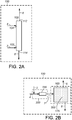
- FIG. 2A illustrates an embodiment of the invention which may be practiced in nitrogen removal or extraction zone 100 that comprises a multi-stage, counter-current extraction column 105 wherein fuel and fuel -immiscible caprolactamium ionic liquid are contacted and separated.
- the fuel feed stream 2 enters extraction column 105 through feed inlet 102 and lean caprolactamium ionic liquid stream 4 enters extraction column 105 through ionic liquid inlet 104.
- reference numerals of the streams and the lines or conduits in which they flow are the same.
- Fuel feed inlet 102 is located below ionic liquid inlet 104.
- the fuel effluent passes through fuel effluent outlet 112 in an upper portion of extraction column 105 to fuel effluent conduit 6.
- caprolactamium ionic liquid effluent including the nitrogen compounds removed from the fuel feed passes through caprolactamium ionic liquid effluent outlet 114 in a lower portion of extraction column 105 to caprolactamium ionic liquid effluent conduit 8.
- FIG. 2B illustrates another embodiment of nitrogen removal washing zone 100 that comprises a contacting zone 200 and a separation zone 300.
- lean caprolactamium ionic liquid stream 4 and fuel feed stream 2 are introduced into the contacting zone 200 and mixed by introducing fuel feed stream 2 into the flowing lean caprolactamium ionic liquid stream 4 and passing the combined streams through static in-line mixer 155.
- Static in-line mixers are well known in the art and may include a conduit with fixed internals such as baffles, fins, and channels that mix the fluid as it flows through the conduit.
- lean caprolactamium ionic liquid stream 4 may be introduced into fuel feed stream 2, or the lean caprolactamium ionic liquid stream 4 and fuel feed stream may be combined such as through a "Y" conduit.
- lean caprolactamium ionic liquid stream 4 and fuel feed stream 2 are separately introduced into the static in-line mixer 155.
- the streams may be mixed by any method well know in the art including stirred tank and blending operations. The mixture comprising fuel and caprolactamium ionic liquid is transferred to separation zone 300 via transfer conduit 7.
- Separation zone 300 comprises separation vessel 165 wherein the two phases are allowed to separate into a rich caprolactamium ionic liquid phase which is withdrawn from a lower portion of separation vessel 165 via caprolactamium ionic liquid effluent conduit 8 and the fuel phase is withdrawn from an upper portion of separation vessel 165 via fuel effluent conduit 6.
- Separation vessel 165 may comprise a boot, not illustrated, from which rich caprolactamium ionic liquid is withdrawn via conduit 8.
- Separation vessel 165 may contain a solid media 175 and/or other coalescing devices which facilitate the phase separation.
- the separation zone 300 may comprise multiple vessels which may be arranged in series, parallel, or a combination thereof.
- the separation vessels may be of any shape and configuration to facilitate the separation, collection, and removal of the two phases.
- nitrogen removal zone 100 may include a single vessel wherein lean caprolactamium ionic liquid stream 4 and fuel feed stream 2 are mixed, then remain in the vessel to settle into the fuel effluent and rich caprolactamium ionic liquid phases.
- the process comprises at least two nitrogen removal steps.
- the fuel effluent from one nitrogen removal step may be passed directly as the fuel feed to a second nitrogen removal step.
- the fuel effluent from one nitrogen removal step may be treated or processed before being introduced as the fuel feed to the second nitrogen removal step.
- each nitrogen removal zone comprises the same type of equipment. Different equipment and conditions may be used in different nitrogen removal zones.
- the nitrogen removal step may be conducted under nitrogen removal conditions including temperatures and pressures sufficient to keep the fuel -immiscible caprolactamium ionic liquid and fuel feeds and effluents as liquids.
- the nitrogen removal step temperature may range between 10°C and less than the decomposition temperature of the caprolactamium ionic liquid; and the pressure may range between atmospheric pressure and 700 kPa(g).
- the decomposition temperature of the caprolactamium ionic liquid is the lowest temperature at which any of the caprolactamium ionic liquid components decompose.
- the nitrogen removal step may be conducted at a uniform temperature and pressure or the contacting and separating steps of the nitrogen removal step may be operated at different temperatures and/or pressures.
- the contacting step is conducted at a first temperature
- the separating step is conducted at a temperature at least 5°C lower than the first temperature.
- the first temperature is 80°C. Such temperature differences may facilitate separation of the fuel and caprolactamium ionic liquid phases.
- the above and other nitrogen removal step conditions such as the contacting or mixing time, the separation or settling time, and the ratio of fuel feed to fuel -immiscible caprolactamium ionic liquid (lean caprolactamium ionic liquid) may vary greatly based, for example, on the specific caprolactamium ionic liquid or liquids employed, the nature of the fuel feed (straight run or previously processed), the nitrogen content of the fuel feed, the degree of nitrogen removal required, the number of nitrogen removal steps employed, and the specific equipment used.
- contacting time may range from less than one minute to two hours; settling time may range from one minute to eight hours; and the weight ratio of fuel feed to lean caprolactamium ionic liquid introduced to the nitrogen removal step may range from 1:10,000 to 10,000:1.
- the weight ratio of fuel feed to lean caprolactamium ionic liquid may range from 1:1,000 to 1,000:1; and the weight ratio of fuel feed to lean caprolactamium ionic liquid may range from 1:100 to 100:1.
- the weight of VGO feed is greater than the weight of caprolactamium ionic liquid introduced to the nitrogen removal step.
- a single nitrogen removal step reduces the nitrogen content of the fuel by more than 40 wt%. In another embodiment, more than 50% of the nitrogen by weight is extracted or removed from the fuel feed 2 in a single nitrogen removal step; and more than 60% of the nitrogen by weight may be extracted or removed from the fuel feed in a single nitrogen removal step. As discussed herein the invention encompasses multiple nitrogen removal steps to provide the desired amount of nitrogen removal. The degree of phase separation between the fuel and caprolactamium ionic liquid phases is another factor to consider as it affects recovery of the caprolactamium ionic liquid and fuel.
- the degree of nitrogen removed and the recovery of the fuel and caprolactamium ionic liquid may be affected differently by the nature of the fuel feed, the variations in the specific caprolactamium ionic liquid or liquids, the equipment, and the nitrogen removal conditions such as those discussed above.
- the amount of water present in the fuel / fuel -immiscible caprolactamium ionic liquid mixture during the nitrogen removal step may also affect the amount of nitrogen removed and/or the degree of phase separation, i.e., recovery of the fuel and caprolactamium ionic liquid.
- the fuel / fuel -immiscible caprolactamium ionic liquid mixture has a water content of less than 10% relative to the weight of the caprolactamium ionic liquid.
- the water content of the fuel / fuel -immiscible caprolactamium ionic liquid mixture is less than 5% relative to the weight of the caprolactamium ionic liquid; and the water content of the fuel / fuel -immiscible caprolactamium ionic liquid mixture may be less than 2% relative to the weight of the ionic liquid.
- the fuel / fuel -immiscible caprolactamium ionic liquid mixture is water free, i.e., the mixture does not contain water.
- connection point of various inlet and effluent streams within the zones is not essential to the invention.
- a stream to a distillation zone may be sent directly to the column, or the stream may first be sent to other equipment within the zone such as heat exchangers, to adjust temperature, and/or pumps to adjust the pressure.
- streams entering and leaving nitrogen removal, washing, and regeneration zones may pass through ancillary equipment such as heat exchanges within the zones.
- Streams, including recycle streams, introduced to washing or extraction zones may be introduced individually or combined prior to or within such zones.
- the invention encompasses a variety of flow scheme embodiments including optional destinations of streams, splitting streams to send the same composition, i.e. aliquot portions, to more than one destination, and recycling various streams within the process. Examples include: various streams comprising ionic liquid and water may be dried and/or passed to other zones to provide all or a portion of the water and/or ionic liquid required by the destination zone.
- the various process steps may be operated continuously and/or intermittently as needed for a given embodiment e.g. based on the quantities and properties of the streams to be processed in such steps.
- the invention encompasses multiple nitrogen removal steps, which may be performed in parallel, sequentially, or a combination thereof. Multiple nitrogen removal steps may be performed within the same nitrogen removal zone and/or multiple nitrogen removal zones may be employed with or without intervening washing, regeneration and/or drying zones.
- caprolactamium ionic liquid was effective in removing nitrogen compounds from the two fuel streams that were processed.
- the large quantities of caprolactamium ionic liquids that are made in the production of caprolactams can now have an additional useful function.
- the caprolactamium ionic liquids may be neutralized and thus turned into caprolactam which may be then purified for sale.
- the present invention provides an additional use for the caprolactamium ionic liquids which can be used in large scale treatment of hydrocarbonaceous fuel streams.
- caprolactamium ionic liquids that are used in the practice of the present invention, may be recycled, purified by removal of impurities that may be introduced from contact with the fuel stream and then used again in the production of caprolactam.
Description
- This invention relates to processes for reducing the nitrogen content of hydrocarbonaceous liquid fuels like vacuum gas oils (VGO) and diesel fuels. More particularly, the invention relates to removing nitrogen contaminants from VGO and diesel fuels using an ionic liquid that is an intermediate in the manufacture of caprolactam.
- VGO is a hydrocarbon fraction that may be converted into higher value hydrocarbon fractions such as diesel fuel, jet fuel, naphtha, gasoline, and other lower boiling fractions in refining processes such as hydrocracking and fluid catalytic cracking (FCC). However, VGO feed streams having higher amounts of nitrogen are more difficult to convert. For example, the degree of conversion, product yields, catalyst deactivation, and/or ability to meet product quality specifications may be adversely affected by the nitrogen content of the feed stream. It is known to reduce the nitrogen content of VGO by catalytic hydrogenation reactions such as in a hydrotreating process unit.
- Similar issues are involved in the processing of diesel fuel. Diesel fuel contains sulfur-containing molecules that are well known pollutants. Therefore, there is an ever increasing need to provide diesel fuels that have ultra low sulfur content. A typical way of removing sulfur from diesel fuel is by catalytic hydrodesulfurization (HDS). It is, however, becoming more difficult to catalytically hydrodesulfurize diesel fuels to the lower level of sulfur now required. Since nitrogen content interferes with the effective removal of sulfur, it is necessary to remove nitrogen prior to removing the sulfur.
- Various processes using ionic liquids to remove sulfur and nitrogen compounds from hydrocarbon fractions are also known.
US 7,001,504 B2 discloses a process for the removal of organosulfur compounds from hydrocarbon materials which includes contacting an ionic liquid with a hydrocarbon material to extract sulfur containing compounds into the ionic liquid.US 7,553,406 B2 discloses a process for removing polarizable impurities from hydrocarbons and mixtures of hydrocarbons using ionic liquids as an extraction medium.US 7,553,406 B2 also discloses that different ionic liquids show different extractive properties for different polarizable compounds.
ChemSusChem 2008, 1, 189-192, Fabos et al.; ε-Caprolactamium Hydrogen Sulfate: An ionic liquid used for decades in the large-scale production of ε -Caprolactam.
US 2010/0243532 describes an apparatus and process for treating a hydrogen stream.
WO 2011/119807 describes an ionic liquid desulfurization process incorporated in a low pressure separator.
US 2009/0120841 describes methods of denitrogenating diesel fuel. - There remains a need in the art for improved processes that enable the removal of compounds comprising nitrogen from vacuum gas oil (VGO) and diesel fuels as well as from other fuels.
- Caprolactamium is an intermediate in the manufacture of caprolactam which in turn is used in the production of engineering polymers such as
polyamide 6. Since millions of tons of caprolactam are used per year, there are correspondingly large amounts of the caprolactamium ionic liquid that are produced. While this ionic liquid has been known for many years, it is shown here to be effective in treatment of fuels, such as diesel fuel and vacuum gas oil. - In an embodiment, the invention is a process for removing a nitrogen compound from a vacuum gas oil comprising contacting the vacuum gas oil with a VGO-immiscible caprolactamium ionic liquid to produce a vacuum gas oil and VGO-immiscible caprolactamium ionic liquid mixture, and separating the mixture to produce a vacuum gas oil effluent and a VGO-immiscible caprolactamium ionic liquid effluent comprising the nitrogen compound. The ionic liquid used in the present invention is shown in the formula below that shows its prior art use in the production of caprolactam.

- In another embodiment, the invention is a process for removing a nitrogen compound from a diesel fuel comprising contacting the diesel fuel with a diesel-immiscible caprolactamium ionic liquid to produce a diesel and diesel-immiscible caprolactamium ionic liquid mixture, and separating the mixture to produce a diesel fuel effluent and a diesel-immiscible caprolactamium ionic liquid effluent comprising the nitrogen compound.
-
-
FIG. 1 is a simplified flow scheme illustrating various embodiments of the invention. -
FIGS. 2A and 2B are simplified flow schemes illustrating different embodiments of an extraction zone of the invention. - In general, the invention may be used to remove a nitrogen compound from a hydrocarbonaceous liquid fuel, more specifically a vacuum gas oil (VGO) hydrocarbon fraction or from diesel fuel through use of a caprolactamium ionic liquid.
- The terms "vacuum gas oil", "VGO", "VGO phase" and similar terms relating to vacuum gas oil as used herein are to be interpreted broadly to receive not only their ordinary meanings as used by those skilled in the art of producing and converting such hydrocarbon fractions, but also in a broad manner to account for the application of our processes to hydrocarbon fractions exhibiting VGO-like characteristics. Thus, the terms encompass straight run VGO as may be produced in a crude fractionation section of an oil refinery, as well as, VGO product cuts, fractions, or streams that may be produced, for example, by coker, deasphalting, and visbreaking processing units, or which may be produced by blending various hydrocarbons.
- In general, VGO comprises petroleum hydrocarbon components boiling in the range of from 100° to 720°C. In an embodiment, the VGO boils from 250° to 650°C and has a density in the range of from 0.87 to 0.95 g/cm3. In another embodiment, the VGO boils from 95° to 580°C; and in a further embodiment, the VGO boils from 300° to 720°C. Generally, VGO may contain from 100 to 30,000 ppm-wt nitrogen; from 1000 to 50,000 ppm-wt sulfur; and from 100 ppb-wt to 2000 ppm-wt of metals. In an embodiment, the nitrogen content of the VGO ranges from 200 to 5000 ppm-wt. In another embodiment, the sulfur content of the VGO ranges from 1000 to 30,000 ppm-wt. The nitrogen content may be determined using ASTM method D4629-02, Trace Nitrogen in Liquid Petroleum Hydrocarbons by Syringe/ Inlet Oxidative Combustion and Chemiluminescence Detection. The sulfur content may be determined using ASTM method D5453-00, Ultraviolet Fluorescence; and the metals content may be determined by UOP389-09, Trace Metals in Oils by Wet Ashing and ICP-OES. Unless otherwise noted, the analytical methods used herein such as ASTM D5453-00 and UOP389-09 are available from ASTM International, 100 Barr Harbor Drive, West Conshohocken, PA, USA.
- The terms "diesel", "diesel fuel", "diesel blends", "diesel phase" and similar terms relating to diesel may be used repeatedly in the description below and the appended claims. The term(s) should be interpreted broadly so that they receive not only their ordinary meanings as used by those skilled in the art such as a distillate fuel used in diesel engines, but in a broader manner to account for the broad application of our processes to fuels exhibiting diesel-like characteristics. Thus, the terms include, but are not limited to, straight run diesel, blended diesel, light cycle oil, light coker gas oil, heavy light cycle oils and the like.
- Processes according to the invention remove a nitrogen compound from fuels such as vacuum gas oil and diesel fuel. That is, the invention removes at least one nitrogen compound. It is understood that the fuel will usually comprise a plurality of nitrogen compounds of different types in various amounts. Thus, the invention removes at least a portion of at least one type of nitrogen compound. The invention may remove the same or different amounts of each type of nitrogen compound, and some types of nitrogen compounds may not be removed. In an embodiment, the nitrogen content fuel is reduced by at least 40 wt%. In another embodiment, the nitrogen content is reduced by at least 75 wt%.
- Ionic liquids are used to extract one or more nitrogen compounds from VGO. Generally, ionic liquids are non-aqueous, organic salts composed of ions where the positive ion is charge balanced with negative ion. These materials have low melting points, often below 100°C, undetectable vapor pressure and good chemical and thermal stability. The cationic charge of the salt is localized over hetero atoms, such as nitrogen, phosphorous, sulfur, arsenic, boron, antimony, and aluminum, and the anions may be any inorganic, organic, or organometallic species.
- Ionic liquids suitable for use in the instant invention are immiscible in the fuel being treated by the caprolactamium ionic liquids. As used herein the term "immiscible ionic liquid" means the ionic liquid immediate that is shown the following reaction equation:

- Consistent with common terms of art, the ionic liquid introduced to the nitrogen removal step may be referred to as a "lean caprolactamium ionic liquid" generally meaning a fuel-immiscible caprolactamium ionic liquid that is not saturated with one or more extracted nitrogen compounds. Lean caprolactamium ionic liquid may include one or both of fresh and regenerated caprolactamium ionic liquid and is suitable for accepting or extracting nitrogen from the fuel feed. Likewise, the caprolactamium ionic liquid effluent may be referred to as "rich caprolactamium ionic liquid", which generally means a fuel -immiscible caprolactamium ionic liquid effluent produced by a nitrogen removal step or process or otherwise including a greater amount of extracted nitrogen compounds than the amount of extracted nitrogen compounds included in the lean caprolactamium ionic liquid. A rich caprolactamium ionic liquid may require regeneration or dilution, e.g. with fresh caprolactamium ionic liquid, before recycling the rich caprolactamium ionic liquid to the same or another nitrogen removal step of the process.
- In an embodiment, the invention is a process for removing nitrogen from vacuum gas oil (VGO), diesel fuel or other fuel comprising a contacting step and a separating step. In the contacting step, a fuel comprising a nitrogen compound and a fuel-immiscible caprolactamium ionic liquid are contacted or mixed. The contacting may facilitate transfer or extraction of the one or more nitrogen compounds from the fuel to the caprolactamium ionic liquid. Although a caprolactamium ionic liquid that is partially soluble in the fuel may facilitate transfer of the nitrogen compound from the fuel to the ionic liquid, partial solubility is not required. Insoluble fuel / caprolactamium ionic liquid mixtures may have sufficient interfacial surface area between the fuel and caprolactamium ionic liquid to be useful. In the separation step, the mixture of fuel and caprolactamium ionic liquid settles or forms two phases, a fuel phase and a caprolactamium ionic liquid phase, which are separated to produce a fuel-immiscible caprolactamium ionic liquid effluent and a vacuum gas oil effluent.
- The process may be conducted in various equipment which are well known in the art and are suitable for batch or continuous operation. For example, in a small scale form of the invention, fuel and a fuel-immiscible caprolactamium ionic liquid may be mixed in a beaker, flask, or other vessel, e.g., by stirring, shaking, use of a mixer, or a magnetic stirrer. The mixing or agitation is stopped and the mixture forms a fuel phase and a caprolactamium ionic liquid phase which can be separated, for example, by decanting, centrifugation, or use of a pipette to produce a fuel effluent having a lower nitrogen content relative to the fuel. The process also produces a fuel -immiscible caprolactamium ionic liquid effluent comprising the one or more nitrogen compounds.
- The contacting and separating steps may be repeated for example when the nitrogen content of the fuel effluent is to be reduced further to obtain a desired nitrogen level in the ultimate fuel product stream from the process. Each set, group, or pair of contacting and separating steps may be referred to as a nitrogen removal step. Thus, the invention encompasses single and multiple nitrogen removal steps. A nitrogen removal zone may be used to perform a nitrogen removal step. As used herein, the term "zone" can refer to one or more equipment items and/or one or more sub-zones. Equipment items may include, for example, one or more vessels, heaters, separators, exchangers, conduits, pumps, compressors, and controllers. Additionally, an equipment item can further include one or more zones or sub-zones. The nitrogen removal process or step may be conducted in a similar manner and with similar equipment as is used to conduct other liquid-liquid wash and extraction operations. Suitable equipment includes, for example, columns with: trays, packing, rotating discs or plates, and static mixers. Pulse columns and mixing / settling tanks may also be used.
-
FIG. 1 is a flow scheme illustrating various embodiments of the invention and some of the optional and/or alternate steps and apparatus encompassed by the invention.Fuel stream 2 and fuel -immiscible caprolactamium ionicliquid stream 4 are introduced to and contacted and separated innitrogen removal zone 100 to produce fuel -immiscible caprolactamium ionicliquid effluent stream 8 andfuel effluent stream 6 as described above. The caprolactamium ionicliquid stream 4 may be comprised of fresh caprolactamium ionicliquid stream 3 and/or one or more caprolactamium ionic liquid streams which are recycled in the process as described below. In an embodiment, a portion or all offuel effluent stream 6 is passed viaconduit 10 to ahydrocarbon conversion zone 800.Hydrocarbon conversion zone 800 may, for example, comprise at least one of an FCC and a hydrocracking process which are well known in the art. - An optional fuel washing step may be used, for example, to recover caprolactamium ionic liquid that is entrained or otherwise remains in the fuel effluent stream by using water to wash or extract the ionic liquid from the fuel effluent. In this embodiment, a portion or all of fuel effluent stream 6 (as feed) and a water stream 12 (as solvent) are introduced to
fuel washing zone 400. The fuel effluent and water streams introduced tofuel washing zone 400 are mixed and separated to produce a washedfuel stream 14 and a spentwater stream 16, which comprises the caprolactamium ionic liquid. The fuel washing step may be conducted in a similar manner and with similar equipment as used to conduct other liquid-liquid wash and extraction operations as discussed above. Various fuel washing step equipment and conditions such as temperature, pressure, times, and solvent to feed ratio may be the same as or different from the nitrogen removal zone equipment and conditions. In general, the fuel washing step conditions will fall within the same ranges as given above for the nitrogen removal step conditions. A portion or all of the washedfuel stream 14 may be passed tohydrocarbon conversion zone 800. - An optional caprolactamium ionic liquid regeneration step may be used, for example, to regenerate the ionic liquid by removing the nitrogen compound from the ionic liquid, i.e. reducing the nitrogen content of the rich caprolactamium ionic liquid. In an embodiment, a portion or all of fuel -immiscible caprolactamium ionic liquid effluent stream 8 (as feed) comprising the nitrogen compound and a
regeneration solvent stream 18 are introduced to ionicliquid regeneration zone 500. The fuel -immiscible caprolactamium ionic liquid effluent and regeneration solvent streams are mixed and separated to produce anextract stream 20 comprising the nitrogen compound, and a regenerated caprolactamium ionicliquid stream 22. The caprolactamium ionic liquid regeneration step may be conducted in a similar manner and with similar equipment as used to conduct other liquid-liquid wash and extraction operations as discussed above. Various caprolactamium ionic liquid regeneration step conditions such as temperature, pressure, times, and solvent to feed may be the same as or different from the nitrogen removal conditions. In general, the ionic liquid regeneration step conditions will fall within the same ranges as given above for the nitrogen removal step conditions. - In an embodiment, the
regeneration solvent stream 18 comprises a hydrocarbon fraction lighter than the fuel and which is immiscible with the caprolactamium ionic liquid. The lighter hydrocarbon fraction may consist of a single hydrocarbon compound or may comprise a mixture of hydrocarbons. In an embodiment, the lighter hydrocarbon fraction comprises at least one of a naphtha, gasoline, diesel, light cycle oil (LCO), and light coker gas oil (LCGO) hydrocarbon fraction. The lighter hydrocarbon fraction may comprise straight run fractions and/or products from conversion processes such as hydrocracking, hydrotreating, fluid catalytic cracking (FCC), reforming, coking, and visbreaking. In this embodiment, extractstream 20 comprises the lighter hydrocarbon regeneration solvent and the nitrogen compound. In another embodiment, theregeneration solvent stream 18 comprises water and the ionic liquid regeneration step producesextract stream 20 comprising the nitrogen compound and regenerated fuel -immiscible caprolactamiumionic liquid 22 comprising water and the caprolactamium ionic liquid. In an embodiment whereinregeneration solvent stream 18 comprises water, a portion or all of spentwater stream 16 may provide a portion or all ofregeneration solvent stream 18. Regardless of whetherregeneration solvent stream 18 comprises a lighter hydrocarbon fraction or water, a portion or all of regenerated VGO-immiscible caprolactamium ionicliquid stream 22 may be recycled to the nitrogen removal step via a conduit not shown consistent with other operating conditions of the process. For example, a constraint on the water content of the VGO-immiscible caprolactamium ionicliquid stream 4 or the caprolactamium ionic liquid / fuel mixture innitrogen removal zone 100 may be met by controlling the proportion and water content of fresh and recycled ionic liquid streams. - Optional ionic liquid drying step is illustrated by drying
zone 600. The ionic liquid drying step may be employed to reduce the water content of one or more of the streams comprising ionic liquid to control the water content of the nitrogen removal step as described above. In the embodiment ofFIG. 1 , a portion or all of regenerated fuel -immiscible caprolactamium ionicliquid stream 22 is introduced to dryingzone 600. Although not shown, other streams comprising ionic liquid such as the fresh caprolactamium ionicliquid stream 3, fuel -immiscible caprolactamium ionicliquid effluent stream 8, and spentwater stream 16, may also be dried in any combination in dryingzone 600. To dry the caprolactamium ionic liquid stream or streams, water may be removed by one or more various well known methods including distillation, flash distillation, and using a dry inert gas to strip water. Generally, the drying temperature may range from 100°C to less than the decomposition temperature of the ionic liquid, usually less than 300°C. The pressure may range from 35 kPa(g) to 250 kPa(g). The drying step produces a dried fuel-immiscible caprolactamium ionicliquid stream 24 and a drying zonewater effluent stream 26. Although not illustrated, a portion or all of dried fuel - immiscible caprolactamium ionicliquid stream 24 may be recycled or passed to provide all or a portion of the fuel-immiscible caprolactamium ionic liquid introduced tonitrogen removal zone 100. A portion or all of drying zonewater effluent stream 26 may be recycled or passed to provide all or a portion of the water introduced intoVGO washing zone 400 and/or ionicliquid regeneration zone 500. - In another embodiment of the invention, the ionic
liquid effluent stream 8 consisting of the spent caprolactamium IL containing the extracted nitrogen species from the hydrocarbonaceous liquid fuel is used directly without regeneration in the production of caprolactam. -
FIG. 2A illustrates an embodiment of the invention which may be practiced in nitrogen removal orextraction zone 100 that comprises a multi-stage,counter-current extraction column 105 wherein fuel and fuel -immiscible caprolactamium ionic liquid are contacted and separated. Thefuel feed stream 2 entersextraction column 105 throughfeed inlet 102 and lean caprolactamium ionicliquid stream 4 entersextraction column 105 through ionicliquid inlet 104. In the FIGURES, reference numerals of the streams and the lines or conduits in which they flow are the same.Fuel feed inlet 102 is located below ionicliquid inlet 104. The fuel effluent passes throughfuel effluent outlet 112 in an upper portion ofextraction column 105 tofuel effluent conduit 6. The fuel -immiscible caprolactamium ionic liquid effluent including the nitrogen compounds removed from the fuel feed passes through caprolactamium ionicliquid effluent outlet 114 in a lower portion ofextraction column 105 to caprolactamium ionicliquid effluent conduit 8. -
FIG. 2B illustrates another embodiment of nitrogenremoval washing zone 100 that comprises a contactingzone 200 and aseparation zone 300. In this embodiment, lean caprolactamium ionicliquid stream 4 andfuel feed stream 2 are introduced into the contactingzone 200 and mixed by introducingfuel feed stream 2 into the flowing lean caprolactamium ionicliquid stream 4 and passing the combined streams through static in-line mixer 155. Static in-line mixers are well known in the art and may include a conduit with fixed internals such as baffles, fins, and channels that mix the fluid as it flows through the conduit. In other embodiments, not illustrated, lean caprolactamium ionicliquid stream 4 may be introduced intofuel feed stream 2, or the lean caprolactamium ionicliquid stream 4 and fuel feed stream may be combined such as through a "Y" conduit. In another embodiment, lean caprolactamium ionicliquid stream 4 andfuel feed stream 2 are separately introduced into the static in-line mixer 155. In other embodiments, the streams may be mixed by any method well know in the art including stirred tank and blending operations. The mixture comprising fuel and caprolactamium ionic liquid is transferred toseparation zone 300 viatransfer conduit 7.Separation zone 300 comprisesseparation vessel 165 wherein the two phases are allowed to separate into a rich caprolactamium ionic liquid phase which is withdrawn from a lower portion ofseparation vessel 165 via caprolactamium ionicliquid effluent conduit 8 and the fuel phase is withdrawn from an upper portion ofseparation vessel 165 viafuel effluent conduit 6.Separation vessel 165 may comprise a boot, not illustrated, from which rich caprolactamium ionic liquid is withdrawn viaconduit 8. -
Separation vessel 165 may contain asolid media 175 and/or other coalescing devices which facilitate the phase separation. In other embodiments theseparation zone 300 may comprise multiple vessels which may be arranged in series, parallel, or a combination thereof. The separation vessels may be of any shape and configuration to facilitate the separation, collection, and removal of the two phases. In a further embodiment,nitrogen removal zone 100 may include a single vessel wherein lean caprolactamium ionicliquid stream 4 andfuel feed stream 2 are mixed, then remain in the vessel to settle into the fuel effluent and rich caprolactamium ionic liquid phases. In an embodiment the process comprises at least two nitrogen removal steps. For example, the fuel effluent from one nitrogen removal step may be passed directly as the fuel feed to a second nitrogen removal step. In another embodiment, the fuel effluent from one nitrogen removal step may be treated or processed before being introduced as the fuel feed to the second nitrogen removal step. There is no requirement that each nitrogen removal zone comprises the same type of equipment. Different equipment and conditions may be used in different nitrogen removal zones. - The nitrogen removal step may be conducted under nitrogen removal conditions including temperatures and pressures sufficient to keep the fuel -immiscible caprolactamium ionic liquid and fuel feeds and effluents as liquids. For example, the nitrogen removal step temperature may range between 10°C and less than the decomposition temperature of the caprolactamium ionic liquid; and the pressure may range between atmospheric pressure and 700 kPa(g). When the fuel -immiscible ionic liquid comprises more than one caprolactamium ionic liquid component, the decomposition temperature of the caprolactamium ionic liquid is the lowest temperature at which any of the caprolactamium ionic liquid components decompose. The nitrogen removal step may be conducted at a uniform temperature and pressure or the contacting and separating steps of the nitrogen removal step may be operated at different temperatures and/or pressures. In an embodiment, the contacting step is conducted at a first temperature, and the separating step is conducted at a temperature at least 5°C lower than the first temperature. In a non limiting example, the first temperature is 80°C. Such temperature differences may facilitate separation of the fuel and caprolactamium ionic liquid phases.
- The above and other nitrogen removal step conditions such as the contacting or mixing time, the separation or settling time, and the ratio of fuel feed to fuel -immiscible caprolactamium ionic liquid (lean caprolactamium ionic liquid) may vary greatly based, for example, on the specific caprolactamium ionic liquid or liquids employed, the nature of the fuel feed (straight run or previously processed), the nitrogen content of the fuel feed, the degree of nitrogen removal required, the number of nitrogen removal steps employed, and the specific equipment used. In general it is expected that contacting time may range from less than one minute to two hours; settling time may range from one minute to eight hours; and the weight ratio of fuel feed to lean caprolactamium ionic liquid introduced to the nitrogen removal step may range from 1:10,000 to 10,000:1. In an embodiment, the weight ratio of fuel feed to lean caprolactamium ionic liquid may range from 1:1,000 to 1,000:1; and the weight ratio of fuel feed to lean caprolactamium ionic liquid may range from 1:100 to 100:1. In an embodiment the weight of VGO feed is greater than the weight of caprolactamium ionic liquid introduced to the nitrogen removal step.
- In an embodiment, a single nitrogen removal step reduces the nitrogen content of the fuel by more than 40 wt%. In another embodiment, more than 50% of the nitrogen by weight is extracted or removed from the
fuel feed 2 in a single nitrogen removal step; and more than 60% of the nitrogen by weight may be extracted or removed from the fuel feed in a single nitrogen removal step. As discussed herein the invention encompasses multiple nitrogen removal steps to provide the desired amount of nitrogen removal. The degree of phase separation between the fuel and caprolactamium ionic liquid phases is another factor to consider as it affects recovery of the caprolactamium ionic liquid and fuel. The degree of nitrogen removed and the recovery of the fuel and caprolactamium ionic liquid may be affected differently by the nature of the fuel feed, the variations in the specific caprolactamium ionic liquid or liquids, the equipment, and the nitrogen removal conditions such as those discussed above. - The amount of water present in the fuel / fuel -immiscible caprolactamium ionic liquid mixture during the nitrogen removal step may also affect the amount of nitrogen removed and/or the degree of phase separation, i.e., recovery of the fuel and caprolactamium ionic liquid. In an embodiment, the fuel / fuel -immiscible caprolactamium ionic liquid mixture has a water content of less than 10% relative to the weight of the caprolactamium ionic liquid. In another embodiment, the water content of the fuel / fuel -immiscible caprolactamium ionic liquid mixture is less than 5% relative to the weight of the caprolactamium ionic liquid; and the water content of the fuel / fuel -immiscible caprolactamium ionic liquid mixture may be less than 2% relative to the weight of the ionic liquid. In a further embodiment, the fuel / fuel -immiscible caprolactamium ionic liquid mixture is water free, i.e., the mixture does not contain water.
- Unless otherwise stated, the exact connection point of various inlet and effluent streams within the zones is not essential to the invention. For example, it is well known in the art that a stream to a distillation zone may be sent directly to the column, or the stream may first be sent to other equipment within the zone such as heat exchangers, to adjust temperature, and/or pumps to adjust the pressure. Likewise, streams entering and leaving nitrogen removal, washing, and regeneration zones may pass through ancillary equipment such as heat exchanges within the zones. Streams, including recycle streams, introduced to washing or extraction zones may be introduced individually or combined prior to or within such zones.
- The invention encompasses a variety of flow scheme embodiments including optional destinations of streams, splitting streams to send the same composition, i.e. aliquot portions, to more than one destination, and recycling various streams within the process. Examples include: various streams comprising ionic liquid and water may be dried and/or passed to other zones to provide all or a portion of the water and/or ionic liquid required by the destination zone. The various process steps may be operated continuously and/or intermittently as needed for a given embodiment e.g. based on the quantities and properties of the streams to be processed in such steps. As discussed above the invention encompasses multiple nitrogen removal steps, which may be performed in parallel, sequentially, or a combination thereof. Multiple nitrogen removal steps may be performed within the same nitrogen removal zone and/or multiple nitrogen removal zones may be employed with or without intervening washing, regeneration and/or drying zones.
- The example is presented to further illustrate some aspects and benefits of the invention and is not to be considered as limiting the scope of the invention. Two extraction experiments were done to investigate whether the caprolactamium IL is efficient at extracting the nitrogen species from HT (hydrotreated) VGO and diesel blend feeds. The samples were mixed for 30 minutes at 60°C with a weight ratio of 0.5:1 = IL:feed. The layers were separated by decantation and the cross-contamination (IL in feed) has been determined via liquid chromatography SO4 2- anion analysis of the HT VGO and diesel phases.
Feed/Ionic Liquid Mixing T (°C) Nitrogen (ppm) % Nitrogen Removed Sulfur (%) Cross-contamination (ppm IL in Feed) HT VGO --- 430 --- 0.11 --- HT VGO + caprolactamium ionic liquid 60 180 58 0.13 312 Diesel Blend --- 650 --- 1.7 --- Diesel + caprolactamium ionic liquid 60 155 76.2 1.67 343 - It was found that the caprolactamium ionic liquid was effective in removing nitrogen compounds from the two fuel streams that were processed. The large quantities of caprolactamium ionic liquids that are made in the production of caprolactams can now have an additional useful function. The caprolactamium ionic liquids may be neutralized and thus turned into caprolactam which may be then purified for sale. The present invention provides an additional use for the caprolactamium ionic liquids which can be used in large scale treatment of hydrocarbonaceous fuel streams. It is also contemplated that the caprolactamium ionic liquids that are used in the practice of the present invention, may be recycled, purified by removal of impurities that may be introduced from contact with the fuel stream and then used again in the production of caprolactam.
Claims (13)
- A process for removing nitrogen compounds from a fuel comprising:(a) contacting the fuel comprising nitrogen compounds with a fuel-immiscible caprolactamium ionic liquid to produce a mixture comprising the fuel and the fuel-immiscible caprolactamium ionic liquid; and(b) separating the mixture to produce a fuel effluent and a fuel-immiscible caprolactamium ionic liquid effluent, the fuel-immiscible caprolactamium ionic liquid effluent comprising the nitrogen compound.
- The process of claim 1 wherein said fuel effluent comprises at least 50% less of said nitrogen compounds than said fuel before being contacted with said caprolactamium ionic liquid.
- The process of claim 1 wherein the mixture further comprises water in an amount less than 10% relative to the amount of fuel-immiscible caprolactamium ionic liquid in the mixture on a weight basis.
- The process of claim 1 further comprising passing at least a portion of the fuel effluent to a hydrocarbon conversion process.
- The process of claim 1 further comprising washing at least a portion of the fuel effluent with water to produce a washed fuel stream and a spent water stream.
- The process of claim 5 further comprising passing at least a portion of the washed fuel effluent stream to a hydrocarbon conversion process.
- The process of claim 1 further comprising contacting the fuel-immiscible caprolactamium ionic liquid effluent with a regeneration solvent and separating the fuel-immiscible caprolactamium ionic liquid effluent from the regeneration solvent to produce an extract stream comprising the nitrogen compound and a regenerated fuel-immiscible caprolactamium ionic liquid stream.
- The process of claim 7 wherein the regeneration solvent comprises a lighter hydrocarbon fraction relative to the fuel and the extract stream further comprises the lighter hydrocarbon fraction, the lighter hydrocarbon fraction being immiscible with the fuel-immiscible caprolactamium ionic liquid.
- The process of claim 1 wherein the fuel effluent comprises fuel-immiscible caprolactamium ionic liquid, further comprising washing at least a portion of the fuel effluent with water to produce a washed vacuum gas oil or diesel fuel and a spent water stream, the spent water stream comprising the fuel-immiscible caprolactamium ionic liquid; wherein at least a portion of the spent water stream is at least a portion of the regeneration solvent.
- The process of claim 1 wherein the fuel-immiscible caprolactamium ionic liquid effluent is purified and is then used in the production of caprolactam.
- The process of any preceding claim, wherein the fuel is either a vacuum gas oil (VGO) hydrocarbon fraction or a diesel fuel.
- The process of claim 1, wherein the weight ratio of the fuel comprising nitrogen compounds with the fuel-immiscible caprolactamium ionic liquid is from 1:1,000 to 1,000:1, preferably from 1:100 to 100:1.
- The process of claim 1, wherein the contacting step (a) is conducted at a first temperature, and the separating step is conducted at a temperature at least 5°C lower than the first temperature.
Applications Claiming Priority (2)
| Application Number | Priority Date | Filing Date | Title |
|---|---|---|---|
| US13/429,596 US8709236B2 (en) | 2012-03-26 | 2012-03-26 | Process for removing nitrogen from fuel streams with caprolactamium ionic liquids |
| PCT/US2013/032748 WO2013148387A1 (en) | 2012-03-26 | 2013-03-18 | Process for removing nitrogen from fuel streams with caprolactamium ionic liquids |
Publications (3)
| Publication Number | Publication Date |
|---|---|
| EP2831202A1 EP2831202A1 (en) | 2015-02-04 |
| EP2831202A4 EP2831202A4 (en) | 2015-10-21 |
| EP2831202B1 true EP2831202B1 (en) | 2017-08-02 |
Family
ID=49210780
Family Applications (1)
| Application Number | Title | Priority Date | Filing Date |
|---|---|---|---|
| EP13770286.6A Active EP2831202B1 (en) | 2012-03-26 | 2013-03-18 | Process for removing nitrogen from fuel streams with caprolactamium ionic liquids |
Country Status (13)
| Country | Link |
|---|---|
| US (1) | US8709236B2 (en) |
| EP (1) | EP2831202B1 (en) |
| JP (1) | JP2015515520A (en) |
| KR (1) | KR101645608B1 (en) |
| CN (1) | CN104204145B (en) |
| BR (1) | BR112014020503B1 (en) |
| CA (1) | CA2864852C (en) |
| DK (1) | DK2831202T3 (en) |
| ES (1) | ES2645438T3 (en) |
| IN (1) | IN2014DN06974A (en) |
| MX (1) | MX337384B (en) |
| SG (1) | SG11201404865TA (en) |
| WO (1) | WO2013148387A1 (en) |
Families Citing this family (8)
| Publication number | Priority date | Publication date | Assignee | Title |
|---|---|---|---|---|
| US9233928B2 (en) * | 2014-05-06 | 2016-01-12 | Uop Llc | Synthesis of lactam based ionic liquid |
| US9416071B2 (en) | 2014-05-06 | 2016-08-16 | Uop Llc | Hydrocarbon conversion processes using lactamium-based ionic liquids |
| US9192928B1 (en) | 2014-11-19 | 2015-11-24 | Uop Llc | Regeneration of an ionic liquid catalyst using metal complexes |
| US9475997B2 (en) | 2014-11-24 | 2016-10-25 | Uop Llc | Contaminant removal from hydrocarbon streams with carbenium pseudo ionic liquids |
| US9574139B2 (en) | 2014-11-24 | 2017-02-21 | Uop Llc | Contaminant removal from hydrocarbon streams with lewis acidic ionic liquids |
| US20160168483A1 (en) * | 2014-12-10 | 2016-06-16 | Uop Llc | Contaminant removal from kerosene streams with lactamium based ionic liquids |
| US20160168482A1 (en) * | 2014-12-12 | 2016-06-16 | Uop Llc | Contaminant removal from hydrocarbon streams with ionic liquids |
| US10384988B2 (en) | 2015-12-23 | 2019-08-20 | Uop Llc | Chloride management in ionic liquid alkylation processes |
Family Cites Families (9)
| Publication number | Priority date | Publication date | Assignee | Title |
|---|---|---|---|---|
| DE10155281A1 (en) * | 2001-11-08 | 2003-06-05 | Solvent Innovation Gmbh | Process for removing polarizable impurities from hydrocarbons and hydrocarbon mixtures by extraction with ionic liquids |
| US7749377B2 (en) | 2007-11-14 | 2010-07-06 | Uop Llc | Methods of denitrogenating diesel fuel |
| CN102131842A (en) | 2008-09-03 | 2011-07-20 | 住友化学株式会社 | Polymer compound and polymer light-emitting element utilizing same |
| US8127938B2 (en) | 2009-03-31 | 2012-03-06 | Uop Llc | Apparatus and process for treating a hydrocarbon stream |
| WO2011026972A1 (en) * | 2009-09-07 | 2011-03-10 | Shell Internationale Research Maatschappij B.V. | Process for the removal of aromatic compounds from a mixture |
| CN101709053A (en) * | 2009-12-14 | 2010-05-19 | 河北瑞通美邦工程有限公司 | Process for preparing caprolactam |
| US8608943B2 (en) | 2009-12-30 | 2013-12-17 | Uop Llc | Process for removing nitrogen from vacuum gas oil |
| US8758600B2 (en) | 2010-03-26 | 2014-06-24 | Saudi Arabian Oil Company | Ionic liquid desulfurization process incorporated in a low pressure separator |
| CN101961598A (en) * | 2010-09-02 | 2011-02-02 | 河北科技大学 | Method for absorbing hydrogen sulfide gas by using ionic liquid |
-
2012
- 2012-03-26 US US13/429,596 patent/US8709236B2/en active Active
-
2013
- 2013-03-18 DK DK13770286.6T patent/DK2831202T3/en active
- 2013-03-18 EP EP13770286.6A patent/EP2831202B1/en active Active
- 2013-03-18 CN CN201380016096.4A patent/CN104204145B/en active Active
- 2013-03-18 MX MX2014011361A patent/MX337384B/en active IP Right Grant
- 2013-03-18 KR KR1020147027359A patent/KR101645608B1/en active IP Right Grant
- 2013-03-18 ES ES13770286.6T patent/ES2645438T3/en active Active
- 2013-03-18 WO PCT/US2013/032748 patent/WO2013148387A1/en active Application Filing
- 2013-03-18 BR BR112014020503-5A patent/BR112014020503B1/en active IP Right Grant
- 2013-03-18 IN IN6974DEN2014 patent/IN2014DN06974A/en unknown
- 2013-03-18 SG SG11201404865TA patent/SG11201404865TA/en unknown
- 2013-03-18 CA CA2864852A patent/CA2864852C/en active Active
- 2013-03-18 JP JP2015503357A patent/JP2015515520A/en not_active Withdrawn
Non-Patent Citations (1)
| Title |
|---|
| None * |
Also Published As
| Publication number | Publication date |
|---|---|
| MX337384B (en) | 2016-03-02 |
| CA2864852C (en) | 2016-04-26 |
| DK2831202T3 (en) | 2017-11-13 |
| KR20140138238A (en) | 2014-12-03 |
| EP2831202A4 (en) | 2015-10-21 |
| BR112014020503B1 (en) | 2020-03-31 |
| US8709236B2 (en) | 2014-04-29 |
| CN104204145A (en) | 2014-12-10 |
| IN2014DN06974A (en) | 2015-04-10 |
| KR101645608B1 (en) | 2016-08-05 |
| CN104204145B (en) | 2015-11-25 |
| JP2015515520A (en) | 2015-05-28 |
| CA2864852A1 (en) | 2013-10-03 |
| MX2014011361A (en) | 2014-10-14 |
| WO2013148387A1 (en) | 2013-10-03 |
| US20130248423A1 (en) | 2013-09-26 |
| SG11201404865TA (en) | 2014-09-26 |
| ES2645438T3 (en) | 2017-12-05 |
| EP2831202A1 (en) | 2015-02-04 |
Similar Documents
| Publication | Publication Date | Title |
|---|---|---|
| CA2772429C (en) | Process for removing metals from vacuum gas oil | |
| EP2831202B1 (en) | Process for removing nitrogen from fuel streams with caprolactamium ionic liquids | |
| US8580107B2 (en) | Process for removing sulfur from vacuum gas oil | |
| US8608943B2 (en) | Process for removing nitrogen from vacuum gas oil | |
| US8608951B2 (en) | Process for removing metals from crude oil | |
| CA2772431C (en) | Process for removing metals from resid | |
| US9328295B2 (en) | Extract recycle in a hydrocarbon decontamination process | |
| US9068127B2 (en) | Process for removing sulfur compounds from vacuum gas oil | |
| US20150361351A1 (en) | Ionic liquid treatment of vacuum slop cut to increase hydrocracking feed | |
| US20140291208A1 (en) | Process for regenerating ionic liquids by adding light hydrocarbon stream |
Legal Events
| Date | Code | Title | Description |
|---|---|---|---|
| PUAI | Public reference made under article 153(3) epc to a published international application that has entered the european phase |
Free format text: ORIGINAL CODE: 0009012 |
|
| 17P | Request for examination filed |
Effective date: 20140910 |
|
| AK | Designated contracting states |
Kind code of ref document: A1 Designated state(s): AL AT BE BG CH CY CZ DE DK EE ES FI FR GB GR HR HU IE IS IT LI LT LU LV MC MK MT NL NO PL PT RO RS SE SI SK SM TR |
|
| AX | Request for extension of the european patent |
Extension state: BA ME |
|
| DAX | Request for extension of the european patent (deleted) | ||
| RA4 | Supplementary search report drawn up and despatched (corrected) |
Effective date: 20150922 |
|
| RIC1 | Information provided on ipc code assigned before grant |
Ipc: C10G 21/28 20060101ALI20150916BHEP Ipc: C10G 31/08 20060101ALI20150916BHEP Ipc: C10G 53/06 20060101ALI20150916BHEP Ipc: C10G 21/27 20060101AFI20150916BHEP |
|
| GRAP | Despatch of communication of intention to grant a patent |
Free format text: ORIGINAL CODE: EPIDOSNIGR1 |
|
| INTG | Intention to grant announced |
Effective date: 20160923 |
|
| GRAJ | Information related to disapproval of communication of intention to grant by the applicant or resumption of examination proceedings by the epo deleted |
Free format text: ORIGINAL CODE: EPIDOSDIGR1 |
|
| GRAP | Despatch of communication of intention to grant a patent |
Free format text: ORIGINAL CODE: EPIDOSNIGR1 |
|
| INTC | Intention to grant announced (deleted) | ||
| INTG | Intention to grant announced |
Effective date: 20170224 |
|
| GRAS | Grant fee paid |
Free format text: ORIGINAL CODE: EPIDOSNIGR3 |
|
| GRAA | (expected) grant |
Free format text: ORIGINAL CODE: 0009210 |
|
| RAP1 | Party data changed (applicant data changed or rights of an application transferred) |
Owner name: HONEYWELL INTERNATIONAL INC. |
|
| RAP1 | Party data changed (applicant data changed or rights of an application transferred) |
Owner name: ADVANSIX RESINS AND CHEMICALS LLC |
|
| AK | Designated contracting states |
Kind code of ref document: B1 Designated state(s): AL AT BE BG CH CY CZ DE DK EE ES FI FR GB GR HR HU IE IS IT LI LT LU LV MC MK MT NL NO PL PT RO RS SE SI SK SM TR |
|
| REG | Reference to a national code |
Ref country code: CH Ref legal event code: EP Ref country code: AT Ref legal event code: REF Ref document number: 914471 Country of ref document: AT Kind code of ref document: T Effective date: 20170815 |
|
| REG | Reference to a national code |
Ref country code: IE Ref legal event code: FG4D |
|
| REG | Reference to a national code |
Ref country code: DE Ref legal event code: R096 Ref document number: 602013024435 Country of ref document: DE |
|
| REG | Reference to a national code |
Ref country code: DK Ref legal event code: T3 Effective date: 20171108 |
|
| REG | Reference to a national code |
Ref country code: NL Ref legal event code: FP |
|
| REG | Reference to a national code |
Ref country code: SE Ref legal event code: TRGR |
|
| REG | Reference to a national code |
Ref country code: ES Ref legal event code: FG2A Ref document number: 2645438 Country of ref document: ES Kind code of ref document: T3 Effective date: 20171205 |
|
| REG | Reference to a national code |
Ref country code: AT Ref legal event code: MK05 Ref document number: 914471 Country of ref document: AT Kind code of ref document: T Effective date: 20170802 |
|
| REG | Reference to a national code |
Ref country code: LT Ref legal event code: MG4D |
|
| PG25 | Lapsed in a contracting state [announced via postgrant information from national office to epo] |
Ref country code: AT Free format text: LAPSE BECAUSE OF FAILURE TO SUBMIT A TRANSLATION OF THE DESCRIPTION OR TO PAY THE FEE WITHIN THE PRESCRIBED TIME-LIMIT Effective date: 20170802 Ref country code: HR Free format text: LAPSE BECAUSE OF FAILURE TO SUBMIT A TRANSLATION OF THE DESCRIPTION OR TO PAY THE FEE WITHIN THE PRESCRIBED TIME-LIMIT Effective date: 20170802 Ref country code: LT Free format text: LAPSE BECAUSE OF FAILURE TO SUBMIT A TRANSLATION OF THE DESCRIPTION OR TO PAY THE FEE WITHIN THE PRESCRIBED TIME-LIMIT Effective date: 20170802 Ref country code: NO Free format text: LAPSE BECAUSE OF FAILURE TO SUBMIT A TRANSLATION OF THE DESCRIPTION OR TO PAY THE FEE WITHIN THE PRESCRIBED TIME-LIMIT Effective date: 20171102 |
|
| PG25 | Lapsed in a contracting state [announced via postgrant information from national office to epo] |
Ref country code: GR Free format text: LAPSE BECAUSE OF FAILURE TO SUBMIT A TRANSLATION OF THE DESCRIPTION OR TO PAY THE FEE WITHIN THE PRESCRIBED TIME-LIMIT Effective date: 20171103 Ref country code: RS Free format text: LAPSE BECAUSE OF FAILURE TO SUBMIT A TRANSLATION OF THE DESCRIPTION OR TO PAY THE FEE WITHIN THE PRESCRIBED TIME-LIMIT Effective date: 20170802 Ref country code: IS Free format text: LAPSE BECAUSE OF FAILURE TO SUBMIT A TRANSLATION OF THE DESCRIPTION OR TO PAY THE FEE WITHIN THE PRESCRIBED TIME-LIMIT Effective date: 20171202 Ref country code: LV Free format text: LAPSE BECAUSE OF FAILURE TO SUBMIT A TRANSLATION OF THE DESCRIPTION OR TO PAY THE FEE WITHIN THE PRESCRIBED TIME-LIMIT Effective date: 20170802 Ref country code: BG Free format text: LAPSE BECAUSE OF FAILURE TO SUBMIT A TRANSLATION OF THE DESCRIPTION OR TO PAY THE FEE WITHIN THE PRESCRIBED TIME-LIMIT Effective date: 20171102 Ref country code: PL Free format text: LAPSE BECAUSE OF FAILURE TO SUBMIT A TRANSLATION OF THE DESCRIPTION OR TO PAY THE FEE WITHIN THE PRESCRIBED TIME-LIMIT Effective date: 20170802 |
|
| REG | Reference to a national code |
Ref country code: FR Ref legal event code: PLFP Year of fee payment: 6 |
|
| PG25 | Lapsed in a contracting state [announced via postgrant information from national office to epo] |
Ref country code: RO Free format text: LAPSE BECAUSE OF FAILURE TO SUBMIT A TRANSLATION OF THE DESCRIPTION OR TO PAY THE FEE WITHIN THE PRESCRIBED TIME-LIMIT Effective date: 20170802 |
|
| REG | Reference to a national code |
Ref country code: DE Ref legal event code: R097 Ref document number: 602013024435 Country of ref document: DE |
|
| PG25 | Lapsed in a contracting state [announced via postgrant information from national office to epo] |
Ref country code: SK Free format text: LAPSE BECAUSE OF FAILURE TO SUBMIT A TRANSLATION OF THE DESCRIPTION OR TO PAY THE FEE WITHIN THE PRESCRIBED TIME-LIMIT Effective date: 20170802 Ref country code: SM Free format text: LAPSE BECAUSE OF FAILURE TO SUBMIT A TRANSLATION OF THE DESCRIPTION OR TO PAY THE FEE WITHIN THE PRESCRIBED TIME-LIMIT Effective date: 20170802 Ref country code: EE Free format text: LAPSE BECAUSE OF FAILURE TO SUBMIT A TRANSLATION OF THE DESCRIPTION OR TO PAY THE FEE WITHIN THE PRESCRIBED TIME-LIMIT Effective date: 20170802 |
|
| PLBE | No opposition filed within time limit |
Free format text: ORIGINAL CODE: 0009261 |
|
| STAA | Information on the status of an ep patent application or granted ep patent |
Free format text: STATUS: NO OPPOSITION FILED WITHIN TIME LIMIT |
|
| 26N | No opposition filed |
Effective date: 20180503 |
|
| PG25 | Lapsed in a contracting state [announced via postgrant information from national office to epo] |
Ref country code: SI Free format text: LAPSE BECAUSE OF FAILURE TO SUBMIT A TRANSLATION OF THE DESCRIPTION OR TO PAY THE FEE WITHIN THE PRESCRIBED TIME-LIMIT Effective date: 20170802 |
|
| REG | Reference to a national code |
Ref country code: CH Ref legal event code: PL |
|
| PG25 | Lapsed in a contracting state [announced via postgrant information from national office to epo] |
Ref country code: MC Free format text: LAPSE BECAUSE OF FAILURE TO SUBMIT A TRANSLATION OF THE DESCRIPTION OR TO PAY THE FEE WITHIN THE PRESCRIBED TIME-LIMIT Effective date: 20170802 |
|
| REG | Reference to a national code |
Ref country code: IE Ref legal event code: MM4A |
|
| PG25 | Lapsed in a contracting state [announced via postgrant information from national office to epo] |
Ref country code: LU Free format text: LAPSE BECAUSE OF NON-PAYMENT OF DUE FEES Effective date: 20180318 |
|
| PG25 | Lapsed in a contracting state [announced via postgrant information from national office to epo] |
Ref country code: IE Free format text: LAPSE BECAUSE OF NON-PAYMENT OF DUE FEES Effective date: 20180318 |
|
| PG25 | Lapsed in a contracting state [announced via postgrant information from national office to epo] |
Ref country code: LI Free format text: LAPSE BECAUSE OF NON-PAYMENT OF DUE FEES Effective date: 20180331 Ref country code: CH Free format text: LAPSE BECAUSE OF NON-PAYMENT OF DUE FEES Effective date: 20180331 |
|
| PG25 | Lapsed in a contracting state [announced via postgrant information from national office to epo] |
Ref country code: MT Free format text: LAPSE BECAUSE OF NON-PAYMENT OF DUE FEES Effective date: 20180318 |
|
| PG25 | Lapsed in a contracting state [announced via postgrant information from national office to epo] |
Ref country code: TR Free format text: LAPSE BECAUSE OF FAILURE TO SUBMIT A TRANSLATION OF THE DESCRIPTION OR TO PAY THE FEE WITHIN THE PRESCRIBED TIME-LIMIT Effective date: 20170802 |
|
| PG25 | Lapsed in a contracting state [announced via postgrant information from national office to epo] |
Ref country code: PT Free format text: LAPSE BECAUSE OF FAILURE TO SUBMIT A TRANSLATION OF THE DESCRIPTION OR TO PAY THE FEE WITHIN THE PRESCRIBED TIME-LIMIT Effective date: 20170802 |
|
| PG25 | Lapsed in a contracting state [announced via postgrant information from national office to epo] |
Ref country code: MK Free format text: LAPSE BECAUSE OF NON-PAYMENT OF DUE FEES Effective date: 20170802 Ref country code: CY Free format text: LAPSE BECAUSE OF FAILURE TO SUBMIT A TRANSLATION OF THE DESCRIPTION OR TO PAY THE FEE WITHIN THE PRESCRIBED TIME-LIMIT Effective date: 20170802 Ref country code: HU Free format text: LAPSE BECAUSE OF FAILURE TO SUBMIT A TRANSLATION OF THE DESCRIPTION OR TO PAY THE FEE WITHIN THE PRESCRIBED TIME-LIMIT; INVALID AB INITIO Effective date: 20130318 |
|
| PG25 | Lapsed in a contracting state [announced via postgrant information from national office to epo] |
Ref country code: AL Free format text: LAPSE BECAUSE OF FAILURE TO SUBMIT A TRANSLATION OF THE DESCRIPTION OR TO PAY THE FEE WITHIN THE PRESCRIBED TIME-LIMIT Effective date: 20170802 |
|
| PGFP | Annual fee paid to national office [announced via postgrant information from national office to epo] |
Ref country code: NL Payment date: 20230215 Year of fee payment: 11 |
|
| PGFP | Annual fee paid to national office [announced via postgrant information from national office to epo] |
Ref country code: DK Payment date: 20230314 Year of fee payment: 11 Ref country code: CZ Payment date: 20230228 Year of fee payment: 11 |
|
| PGFP | Annual fee paid to national office [announced via postgrant information from national office to epo] |
Ref country code: SE Payment date: 20230110 Year of fee payment: 11 Ref country code: IT Payment date: 20230213 Year of fee payment: 11 Ref country code: GB Payment date: 20230126 Year of fee payment: 11 Ref country code: DE Payment date: 20230125 Year of fee payment: 11 Ref country code: BE Payment date: 20230216 Year of fee payment: 11 |
|
| P01 | Opt-out of the competence of the unified patent court (upc) registered |
Effective date: 20230502 |
|
| PGFP | Annual fee paid to national office [announced via postgrant information from national office to epo] |
Ref country code: ES Payment date: 20230407 Year of fee payment: 11 |
|
| PGFP | Annual fee paid to national office [announced via postgrant information from national office to epo] |
Ref country code: FR Payment date: 20231229 Year of fee payment: 12 Ref country code: FI Payment date: 20231218 Year of fee payment: 12 |
|
| PGFP | Annual fee paid to national office [announced via postgrant information from national office to epo] |
Ref country code: NL Payment date: 20240108 Year of fee payment: 12 |