EP2830992B1 - Integrated process for the gasification of whole crude oil in a membrane wall gasifier and power generation - Google Patents
Integrated process for the gasification of whole crude oil in a membrane wall gasifier and power generation Download PDFInfo
- Publication number
- EP2830992B1 EP2830992B1 EP13716566.8A EP13716566A EP2830992B1 EP 2830992 B1 EP2830992 B1 EP 2830992B1 EP 13716566 A EP13716566 A EP 13716566A EP 2830992 B1 EP2830992 B1 EP 2830992B1
- Authority
- EP
- European Patent Office
- Prior art keywords
- crude oil
- range
- whole crude
- steam
- gasification reactor
- Prior art date
- Legal status (The legal status is an assumption and is not a legal conclusion. Google has not performed a legal analysis and makes no representation as to the accuracy of the status listed.)
- Active
Links
Images

Classifications
-
- C—CHEMISTRY; METALLURGY
- C01—INORGANIC CHEMISTRY
- C01B—NON-METALLIC ELEMENTS; COMPOUNDS THEREOF; METALLOIDS OR COMPOUNDS THEREOF NOT COVERED BY SUBCLASS C01C
- C01B3/00—Hydrogen; Gaseous mixtures containing hydrogen; Separation of hydrogen from mixtures containing it; Purification of hydrogen
- C01B3/02—Production of hydrogen or of gaseous mixtures containing a substantial proportion of hydrogen
- C01B3/32—Production of hydrogen or of gaseous mixtures containing a substantial proportion of hydrogen by reaction of gaseous or liquid organic compounds with gasifying agents, e.g. water, carbon dioxide, air
- C01B3/34—Production of hydrogen or of gaseous mixtures containing a substantial proportion of hydrogen by reaction of gaseous or liquid organic compounds with gasifying agents, e.g. water, carbon dioxide, air by reaction of hydrocarbons with gasifying agents
- C01B3/36—Production of hydrogen or of gaseous mixtures containing a substantial proportion of hydrogen by reaction of gaseous or liquid organic compounds with gasifying agents, e.g. water, carbon dioxide, air by reaction of hydrocarbons with gasifying agents using oxygen or mixtures containing oxygen as gasifying agents
-
- C—CHEMISTRY; METALLURGY
- C01—INORGANIC CHEMISTRY
- C01B—NON-METALLIC ELEMENTS; COMPOUNDS THEREOF; METALLOIDS OR COMPOUNDS THEREOF NOT COVERED BY SUBCLASS C01C
- C01B3/00—Hydrogen; Gaseous mixtures containing hydrogen; Separation of hydrogen from mixtures containing it; Purification of hydrogen
- C01B3/02—Production of hydrogen or of gaseous mixtures containing a substantial proportion of hydrogen
- C01B3/22—Production of hydrogen or of gaseous mixtures containing a substantial proportion of hydrogen by decomposition of gaseous or liquid organic compounds
-
- C—CHEMISTRY; METALLURGY
- C01—INORGANIC CHEMISTRY
- C01B—NON-METALLIC ELEMENTS; COMPOUNDS THEREOF; METALLOIDS OR COMPOUNDS THEREOF NOT COVERED BY SUBCLASS C01C
- C01B3/00—Hydrogen; Gaseous mixtures containing hydrogen; Separation of hydrogen from mixtures containing it; Purification of hydrogen
- C01B3/02—Production of hydrogen or of gaseous mixtures containing a substantial proportion of hydrogen
- C01B3/32—Production of hydrogen or of gaseous mixtures containing a substantial proportion of hydrogen by reaction of gaseous or liquid organic compounds with gasifying agents, e.g. water, carbon dioxide, air
- C01B3/34—Production of hydrogen or of gaseous mixtures containing a substantial proportion of hydrogen by reaction of gaseous or liquid organic compounds with gasifying agents, e.g. water, carbon dioxide, air by reaction of hydrocarbons with gasifying agents
- C01B3/48—Production of hydrogen or of gaseous mixtures containing a substantial proportion of hydrogen by reaction of gaseous or liquid organic compounds with gasifying agents, e.g. water, carbon dioxide, air by reaction of hydrocarbons with gasifying agents followed by reaction of water vapour with carbon monoxide
-
- C—CHEMISTRY; METALLURGY
- C10—PETROLEUM, GAS OR COKE INDUSTRIES; TECHNICAL GASES CONTAINING CARBON MONOXIDE; FUELS; LUBRICANTS; PEAT
- C10J—PRODUCTION OF PRODUCER GAS, WATER-GAS, SYNTHESIS GAS FROM SOLID CARBONACEOUS MATERIAL, OR MIXTURES CONTAINING THESE GASES; CARBURETTING AIR OR OTHER GASES
- C10J3/00—Production of combustible gases containing carbon monoxide from solid carbonaceous fuels
- C10J3/46—Gasification of granular or pulverulent flues in suspension
- C10J3/48—Apparatus; Plants
- C10J3/485—Entrained flow gasifiers
-
- C—CHEMISTRY; METALLURGY
- C10—PETROLEUM, GAS OR COKE INDUSTRIES; TECHNICAL GASES CONTAINING CARBON MONOXIDE; FUELS; LUBRICANTS; PEAT
- C10J—PRODUCTION OF PRODUCER GAS, WATER-GAS, SYNTHESIS GAS FROM SOLID CARBONACEOUS MATERIAL, OR MIXTURES CONTAINING THESE GASES; CARBURETTING AIR OR OTHER GASES
- C10J3/00—Production of combustible gases containing carbon monoxide from solid carbonaceous fuels
- C10J3/72—Other features
- C10J3/74—Construction of shells or jackets
-
- F—MECHANICAL ENGINEERING; LIGHTING; HEATING; WEAPONS; BLASTING
- F01—MACHINES OR ENGINES IN GENERAL; ENGINE PLANTS IN GENERAL; STEAM ENGINES
- F01K—STEAM ENGINE PLANTS; STEAM ACCUMULATORS; ENGINE PLANTS NOT OTHERWISE PROVIDED FOR; ENGINES USING SPECIAL WORKING FLUIDS OR CYCLES
- F01K25/00—Plants or engines characterised by use of special working fluids, not otherwise provided for; Plants operating in closed cycles and not otherwise provided for
-
- F—MECHANICAL ENGINEERING; LIGHTING; HEATING; WEAPONS; BLASTING
- F02—COMBUSTION ENGINES; HOT-GAS OR COMBUSTION-PRODUCT ENGINE PLANTS
- F02C—GAS-TURBINE PLANTS; AIR INTAKES FOR JET-PROPULSION PLANTS; CONTROLLING FUEL SUPPLY IN AIR-BREATHING JET-PROPULSION PLANTS
- F02C3/00—Gas-turbine plants characterised by the use of combustion products as the working fluid
- F02C3/20—Gas-turbine plants characterised by the use of combustion products as the working fluid using a special fuel, oxidant, or dilution fluid to generate the combustion products
- F02C3/26—Gas-turbine plants characterised by the use of combustion products as the working fluid using a special fuel, oxidant, or dilution fluid to generate the combustion products the fuel or oxidant being solid or pulverulent, e.g. in slurry or suspension
- F02C3/28—Gas-turbine plants characterised by the use of combustion products as the working fluid using a special fuel, oxidant, or dilution fluid to generate the combustion products the fuel or oxidant being solid or pulverulent, e.g. in slurry or suspension using a separate gas producer for gasifying the fuel before combustion
-
- C—CHEMISTRY; METALLURGY
- C10—PETROLEUM, GAS OR COKE INDUSTRIES; TECHNICAL GASES CONTAINING CARBON MONOXIDE; FUELS; LUBRICANTS; PEAT
- C10J—PRODUCTION OF PRODUCER GAS, WATER-GAS, SYNTHESIS GAS FROM SOLID CARBONACEOUS MATERIAL, OR MIXTURES CONTAINING THESE GASES; CARBURETTING AIR OR OTHER GASES
- C10J2300/00—Details of gasification processes
- C10J2300/09—Details of the feed, e.g. feeding of spent catalyst, inert gas or halogens
- C10J2300/0903—Feed preparation
-
- C—CHEMISTRY; METALLURGY
- C10—PETROLEUM, GAS OR COKE INDUSTRIES; TECHNICAL GASES CONTAINING CARBON MONOXIDE; FUELS; LUBRICANTS; PEAT
- C10J—PRODUCTION OF PRODUCER GAS, WATER-GAS, SYNTHESIS GAS FROM SOLID CARBONACEOUS MATERIAL, OR MIXTURES CONTAINING THESE GASES; CARBURETTING AIR OR OTHER GASES
- C10J2300/00—Details of gasification processes
- C10J2300/09—Details of the feed, e.g. feeding of spent catalyst, inert gas or halogens
- C10J2300/0913—Carbonaceous raw material
- C10J2300/093—Coal
-
- C—CHEMISTRY; METALLURGY
- C10—PETROLEUM, GAS OR COKE INDUSTRIES; TECHNICAL GASES CONTAINING CARBON MONOXIDE; FUELS; LUBRICANTS; PEAT
- C10J—PRODUCTION OF PRODUCER GAS, WATER-GAS, SYNTHESIS GAS FROM SOLID CARBONACEOUS MATERIAL, OR MIXTURES CONTAINING THESE GASES; CARBURETTING AIR OR OTHER GASES
- C10J2300/00—Details of gasification processes
- C10J2300/09—Details of the feed, e.g. feeding of spent catalyst, inert gas or halogens
- C10J2300/0953—Gasifying agents
- C10J2300/0959—Oxygen
-
- C—CHEMISTRY; METALLURGY
- C10—PETROLEUM, GAS OR COKE INDUSTRIES; TECHNICAL GASES CONTAINING CARBON MONOXIDE; FUELS; LUBRICANTS; PEAT
- C10J—PRODUCTION OF PRODUCER GAS, WATER-GAS, SYNTHESIS GAS FROM SOLID CARBONACEOUS MATERIAL, OR MIXTURES CONTAINING THESE GASES; CARBURETTING AIR OR OTHER GASES
- C10J2300/00—Details of gasification processes
- C10J2300/09—Details of the feed, e.g. feeding of spent catalyst, inert gas or halogens
- C10J2300/0983—Additives
- C10J2300/0989—Hydrocarbons as additives to gasifying agents to improve caloric properties
-
- C—CHEMISTRY; METALLURGY
- C10—PETROLEUM, GAS OR COKE INDUSTRIES; TECHNICAL GASES CONTAINING CARBON MONOXIDE; FUELS; LUBRICANTS; PEAT
- C10J—PRODUCTION OF PRODUCER GAS, WATER-GAS, SYNTHESIS GAS FROM SOLID CARBONACEOUS MATERIAL, OR MIXTURES CONTAINING THESE GASES; CARBURETTING AIR OR OTHER GASES
- C10J2300/00—Details of gasification processes
- C10J2300/16—Integration of gasification processes with another plant or parts within the plant
- C10J2300/164—Integration of gasification processes with another plant or parts within the plant with conversion of synthesis gas
- C10J2300/1643—Conversion of synthesis gas to energy
- C10J2300/1653—Conversion of synthesis gas to energy integrated in a gasification combined cycle [IGCC]
-
- C—CHEMISTRY; METALLURGY
- C10—PETROLEUM, GAS OR COKE INDUSTRIES; TECHNICAL GASES CONTAINING CARBON MONOXIDE; FUELS; LUBRICANTS; PEAT
- C10J—PRODUCTION OF PRODUCER GAS, WATER-GAS, SYNTHESIS GAS FROM SOLID CARBONACEOUS MATERIAL, OR MIXTURES CONTAINING THESE GASES; CARBURETTING AIR OR OTHER GASES
- C10J2300/00—Details of gasification processes
- C10J2300/16—Integration of gasification processes with another plant or parts within the plant
- C10J2300/1671—Integration of gasification processes with another plant or parts within the plant with the production of electricity
- C10J2300/1675—Integration of gasification processes with another plant or parts within the plant with the production of electricity making use of a steam turbine
-
- C—CHEMISTRY; METALLURGY
- C10—PETROLEUM, GAS OR COKE INDUSTRIES; TECHNICAL GASES CONTAINING CARBON MONOXIDE; FUELS; LUBRICANTS; PEAT
- C10J—PRODUCTION OF PRODUCER GAS, WATER-GAS, SYNTHESIS GAS FROM SOLID CARBONACEOUS MATERIAL, OR MIXTURES CONTAINING THESE GASES; CARBURETTING AIR OR OTHER GASES
- C10J2300/00—Details of gasification processes
- C10J2300/16—Integration of gasification processes with another plant or parts within the plant
- C10J2300/1678—Integration of gasification processes with another plant or parts within the plant with air separation
-
- C—CHEMISTRY; METALLURGY
- C10—PETROLEUM, GAS OR COKE INDUSTRIES; TECHNICAL GASES CONTAINING CARBON MONOXIDE; FUELS; LUBRICANTS; PEAT
- C10J—PRODUCTION OF PRODUCER GAS, WATER-GAS, SYNTHESIS GAS FROM SOLID CARBONACEOUS MATERIAL, OR MIXTURES CONTAINING THESE GASES; CARBURETTING AIR OR OTHER GASES
- C10J2300/00—Details of gasification processes
- C10J2300/18—Details of the gasification process, e.g. loops, autothermal operation
- C10J2300/1846—Partial oxidation, i.e. injection of air or oxygen only
-
- C—CHEMISTRY; METALLURGY
- C10—PETROLEUM, GAS OR COKE INDUSTRIES; TECHNICAL GASES CONTAINING CARBON MONOXIDE; FUELS; LUBRICANTS; PEAT
- C10J—PRODUCTION OF PRODUCER GAS, WATER-GAS, SYNTHESIS GAS FROM SOLID CARBONACEOUS MATERIAL, OR MIXTURES CONTAINING THESE GASES; CARBURETTING AIR OR OTHER GASES
- C10J3/00—Production of combustible gases containing carbon monoxide from solid carbonaceous fuels
- C10J3/72—Other features
- C10J3/86—Other features combined with waste-heat boilers
-
- C—CHEMISTRY; METALLURGY
- C10—PETROLEUM, GAS OR COKE INDUSTRIES; TECHNICAL GASES CONTAINING CARBON MONOXIDE; FUELS; LUBRICANTS; PEAT
- C10K—PURIFYING OR MODIFYING THE CHEMICAL COMPOSITION OF COMBUSTIBLE GASES CONTAINING CARBON MONOXIDE
- C10K1/00—Purifying combustible gases containing carbon monoxide
- C10K1/002—Removal of contaminants
- C10K1/003—Removal of contaminants of acid contaminants, e.g. acid gas removal
-
- C—CHEMISTRY; METALLURGY
- C10—PETROLEUM, GAS OR COKE INDUSTRIES; TECHNICAL GASES CONTAINING CARBON MONOXIDE; FUELS; LUBRICANTS; PEAT
- C10K—PURIFYING OR MODIFYING THE CHEMICAL COMPOSITION OF COMBUSTIBLE GASES CONTAINING CARBON MONOXIDE
- C10K3/00—Modifying the chemical composition of combustible gases containing carbon monoxide to produce an improved fuel, e.g. one of different calorific value, which may be free from carbon monoxide
- C10K3/02—Modifying the chemical composition of combustible gases containing carbon monoxide to produce an improved fuel, e.g. one of different calorific value, which may be free from carbon monoxide by catalytic treatment
- C10K3/04—Modifying the chemical composition of combustible gases containing carbon monoxide to produce an improved fuel, e.g. one of different calorific value, which may be free from carbon monoxide by catalytic treatment reducing the carbon monoxide content, e.g. water-gas shift [WGS]
-
- F—MECHANICAL ENGINEERING; LIGHTING; HEATING; WEAPONS; BLASTING
- F05—INDEXING SCHEMES RELATING TO ENGINES OR PUMPS IN VARIOUS SUBCLASSES OF CLASSES F01-F04
- F05D—INDEXING SCHEME FOR ASPECTS RELATING TO NON-POSITIVE-DISPLACEMENT MACHINES OR ENGINES, GAS-TURBINES OR JET-PROPULSION PLANTS
- F05D2220/00—Application
- F05D2220/70—Application in combination with
- F05D2220/72—Application in combination with a steam turbine
- F05D2220/722—Application in combination with a steam turbine as part of an integrated gasification combined cycle
-
- Y—GENERAL TAGGING OF NEW TECHNOLOGICAL DEVELOPMENTS; GENERAL TAGGING OF CROSS-SECTIONAL TECHNOLOGIES SPANNING OVER SEVERAL SECTIONS OF THE IPC; TECHNICAL SUBJECTS COVERED BY FORMER USPC CROSS-REFERENCE ART COLLECTIONS [XRACs] AND DIGESTS
- Y02—TECHNOLOGIES OR APPLICATIONS FOR MITIGATION OR ADAPTATION AGAINST CLIMATE CHANGE
- Y02E—REDUCTION OF GREENHOUSE GAS [GHG] EMISSIONS, RELATED TO ENERGY GENERATION, TRANSMISSION OR DISTRIBUTION
- Y02E20/00—Combustion technologies with mitigation potential
- Y02E20/16—Combined cycle power plant [CCPP], or combined cycle gas turbine [CCGT]
- Y02E20/18—Integrated gasification combined cycle [IGCC], e.g. combined with carbon capture and storage [CCS]
-
- Y—GENERAL TAGGING OF NEW TECHNOLOGICAL DEVELOPMENTS; GENERAL TAGGING OF CROSS-SECTIONAL TECHNOLOGIES SPANNING OVER SEVERAL SECTIONS OF THE IPC; TECHNICAL SUBJECTS COVERED BY FORMER USPC CROSS-REFERENCE ART COLLECTIONS [XRACs] AND DIGESTS
- Y02—TECHNOLOGIES OR APPLICATIONS FOR MITIGATION OR ADAPTATION AGAINST CLIMATE CHANGE
- Y02P—CLIMATE CHANGE MITIGATION TECHNOLOGIES IN THE PRODUCTION OR PROCESSING OF GOODS
- Y02P20/00—Technologies relating to chemical industry
- Y02P20/10—Process efficiency
Definitions
- the present invention relates to processes for the partial oxidation of a whole crude oil feedstock in a membrane wall gasification reactor to produce a synthesis gas and electricity.
- Gasification is well known in the art and it is practiced worldwide with application to solids and heavy liquid fossil fuels, including refinery bottoms.
- the gasification process uses partial oxidation to convert carbonaceous materials, such as coal, petroleum, biofuel, or biomass with oxygen at high temperature, i.e., greater than 800°C, into synthesis gas ("syngas"), steam and electricity.
- syngas consisting of carbon monoxide and hydrogen can be burned directly in internal combustion engines, or used in the manufacture of various chemicals, such as methanol via known synthesis processes and to make synthetic fuels via the Fischer-Tropsch process.
- FIG. 1 shows the process flow diagram of a conventional IGCC of the prior art, which includes a feed preparation section 102, a gasification reactor 104, an air separation unit 180, a syngas quench and cooling unit 110, a water-gas shift reactor 120, an acid gas removal (AGR) and sulfur recovery unit (SRU) 130, a gas turbine 140, a heat recovery steam generator (HRSG) 150, and a steam turbine 160.
- IGCC Integrated Gasification Combined Cycle
- a feedstock is introduced via a feed line 101 to the feed preparation section 102.
- the prepared feedstock is then passed to the gasification reactor 104 with a predetermined amount of oxygen 103 produced from the air separation unit 180.
- the feedstock is partially oxidized in the gasification reactor 104 to produce a hot syngas 106 which is conveyed to the syngas quench and cooling unit 110.
- Hot syngas 106 is cooled with boiler feed water 156 to produce cooled syngas 114 and steam.
- a portion of the steam 112 is passed to and used in the water-gas shift reactor 120 to produce shifted gas 122, and the remaining portion of the steam 116 is consumed in the HRSG 150.
- Shifted gas 122 is treated in the AGR/SRU 130 to separate and discharge carbon dioxide 136, sulfur 138; a portion of the hydrogen syngas which is recovered at 132.
- a second portion of the hydrogen syngas, identified as gas turbine feed 134, is passed to the gas turbine 140 with air feed 142 and combusted to produce electricity 144.
- the high pressure combustion gas discharge 146 from the gas turbine 140 is conveyed to the HRSG 150 to generate steam which is used in the steam turbine 160 to produce additional electricity 162.
- the air separation unit 180 and most of the downstream processes utilize mature technologies with high on-stream reliability factors.
- the gasification reactor 104 has a relatively limited lifetime which can be as short as from 3 to 18 months, depending upon the characteristics of the feed and the design of the reactor.
- the three principal types of gasification reactor technologies are the moving bed, fluidized bed and entrained-flow systems. Each of the three types can be used with solid fuels, but only the entrained-flow reactor has been demonstrated to efficiently process liquid fuels.
- the fuel, oxygen and steam are injected at the top of the gasifier through a co-annular burner.
- the gasification usually takes place in a refractory-lined vessel which operates at a pressure of about 40 bars to 60 bars and a temperature in the range of from 1300°C to 1700°C.
- gasifier wall construction There are two types of gasifier wall construction: refractory and membrane.
- the gasifier conventionally uses refractory liners to protect the reactor vessel from corrosive slag, thermal cycling, and the elevated temperatures that range from 1400°C to 1700°C.
- the refractory is subjected to the penetration of corrosive components from the generation of the syngas and slag and, thereafter, to subsequent reactions in which the reactants undergo significant volume changes that result in strength degradation of the refractory materials.
- the replacement of the degraded refractory linings can cost several millions of dollars a year and several weeks of downtime for a given reactor. Up until now, the solution has been the installation of a second or parallel gasifier to provide the necessary continuous operating capability during maintenance downtime, but the undesirable consequence of this duplication is a significant increase in the capital costs associated with the unit operation.
- An alternative membrane wall gasifier technology uses a cooling screen protected by a layer of refractory material to provide a surface on which the molten slag solidifies and flows downwardly to the quench zone at the bottom of the reactor.
- the advantages of the membrane wall reactor include reduced reactor dimensions as compared to other systems; a significantly greater average on-stream time of 90%, as compared to an on-stream time of 50% for a refractory wall reactor; elimination of the need to have a parallel reactor to maintain continuous operation as in the case of refractory wall reactors; and the build-up of a layer of solid and liquid slag that provides self-protection to the water-cooled wall sections.
- a membrane wall gasifier In a membrane wall gasifier, the build-up of a layer of solidified mineral ash slag on the wall acts as an additional protective surface and insulator to minimize or reduce refractory degradation and heat losses through the wall.
- the water-cooled reactor design also avoids what is termed "hot wall” gasifier operation, which requires the construction of thick multiple-layers of expensive refractories which are subject to degradation.
- the slag layer is renewed continuously with the deposit of solids on the relatively cool surface.
- a second solid feedstock reactor uses spiral tubes and down-flow processing for all fuels.
- solid fuels e.g., petcoke.
- a single burner having a thermal output of about 500MWt has been developed for commercial use.
- the flow of pressurized cooling water in the tubes is controlled to cool the refractory and ensure the downward flow of the molten slag. Both systems have demonstrated high utility with solid fuels, but not with liquid fuels.
- the gasification reactor is operated to produce synthesis gas, or syngas.
- syngas For the production of liquid fuels and petrochemicals, the key parameter is the mole ratio of hydrogen-to-carbon monoxide in the dry syngas. This ratio is usually between 0.85:1 and 1.2:1, depending upon the characteristics of the feedstock. Additional treatment of the syngas is needed to increase this ratio of hydrocarbon-to-carbon to 2:1 for Fischer-Tropsch applications, or to produce additional hydrogen through the water-gas shift reaction represented by CO+H 2 O ⁇ CO 2 +H 2 . In some cases, part of the syngas is burned together with some of the off gases in a combined cycle to produce electricity and steam. The overall efficiency of this process is between 44% and 48%.
- WO 2013/015899 A1 discloses a process for the gasification of heavy residual oil with particulate coke using a membrane wall gasification reactor in order to produce synthesis gas and electricity.
- WO 2012/047439 discloses a process for the gasification of waste tires with residual oils using a membrane wall gasification reactor in order to produce synthesis gas and electricity.
- whole crude oil is initially processed in an atmospheric distillation column or a crude tower where it is separated into a variety of different components including naphtha boiling in the range of from 36°C to 180°C, diesel boiling in the range of from 180°C to 370°C, and atmospheric bottoms boiling above 370°C.
- the atmospheric bottoms residue is further processed in a vacuum distillation column where it is separated into a vacuum gas oil (VGO) boiling in the range of from 370°C to 520°C and a heavy vacuum residue boiling above 520°C.
- VGO vacuum gas oil
- the VGO can be further processed by hydrocracking to produce naphtha and diesel, or by fluid catalytic cracking (FCC) to produce gasoline and cycle oils.
- FCC fluid catalytic cracking
- the heavy vacuum residue can be treated to remove unwanted impurities or converted into useful hydrocarbon products.
- the problem addressed by the present invention is that of directly converting a whole crude oil feedstock of relatively low value in a process that is economically viable, and that is capable of producing a syngas and/or an enriched hydrogen system that can be used as a feedstream for other processes in the same refinery, or used to produce methanol and/or synthetic fuels.
- the present invention comprehends the integrated processing of whole crude oil by the partial oxidation of the feedstock in a membrane wall gasification reactor to produce a syngas and/or hydrogen and to generate electrical power.
- the process for gasification of the whole crude oil further includes a water-gas shift reaction vessel to convert carbon monoxide to hydrogen through the water-gas shift reaction represented by CO+H 2 O ⁇ CO 2 +H 2 , to thereby increase the volume of hydrogen in the shifted syngas.
- ash-producing material and “ash-forming material” are synonymous, and refers to a material that produces a solid ash to form slag in the membrane wall reactor.
- the solid ash-producing material used in the process of the invention is selected from the group consisting of natural and synthetic oxides of Si, Al, Fe, Ca, Mg, P, K, Na, S and Ti, and mixtures thereof, and is in the form of finely divided particles and is mixed with the whole crude oil and constitutes 2% to 5% by weight of the total weight of the feedstock.
- the whole crude oil gasification apparatus 200 includes a membrane wall gasification reactor 210, a heat exchanger 220, a turbine 230 and a water-gas shift reaction vessel 240. Note that while the embodiment of apparatus 200 described herein includes a water-gas shift reaction vessel to enhance the output of hydrogen by conversion of some or all of the carbon monoxide in the syngas, alternative embodiments similar to apparatus 200 can be practiced without the water-gas shift reaction vessel.
- Membrane wall gasification reactor 210 includes an inlet 211 in fluid communication with a conduit 213 for introducing a whole crude oil feedstock, a conduit 219 for introducing a controlled amount of solid ash-producing material, a conduit 215 for introducing a controlled amount of a pressurized stream of oxygen or an oxygen-containing gas, and a conduit 217 for introducing a controlled amount of steam.
- Membrane wall gasification reactor 210 also includes an outlet 212 for discharging hot raw syngas.
- Heat exchanger 220 includes an inlet 221 in fluid communication with outlet 212 of the membrane wall gasification reactor 210, an outlet 222 for discharging steam, and an outlet 224 for discharging cooled syngas.
- Turbine 230 includes an inlet 231 in fluid communication with outlet 222 of the heat exchanger 220, and an electrical conductor 232 for transmitting the electricity generated, and an outlet 234 for low pressure stream.
- the optional water-gas shift reaction vessel 240 includes an inlet 241 in fluid communication with outlet 224 of the heat exchanger 220 via a three-way valve 226 for receiving cooled syngas and a conduit 243 for introducing a controlled amount of steam, and an outlet 242 for discharging the hydrogen rich shifted syngas product.
- a whole crude oil feedstock is introduced as a pressurized feedstream via conduit 213 into the membrane wall gasification reactor 210 along with a predetermined amount of solid ash-producing material via conduit 219, a predetermined amount of oxygen or an oxygen-containing gas via conduit 215 and a predetermined amount of steam via conduit 217.
- an analysis of the carbon content of the crude oil feed should previously be obtained in order to determine the stoichiometric amount of oxygen that is to be introduced into the gasifier.
- One method of carbon analysis that is suited for this purpose is described in ASTM D-5291.
- the whole crude oil and solid material are mixed, e.g., using an inline mixer, a flow-through mixing vessel or other known apparatus.
- the mixture of crude oil and solid ash-producing material is partially oxidized in the membrane wall gasification reactor 210 to produce hydrogen and carbon monoxide in the form of a hot raw syngas.
- a particular advantage of the process of the invention is that no auxiliary or supplemental fuel gas is required in order to maintain the gasification temperature, since all of the fuel values required for combustion are present in the lighter components of the whole crude oil.
- the slag formed in the gasification reactor from the ash-producing material is also supplemented by some of the constituents that are present in the crude oil.
- Hot raw syngas is discharged from outlet 212 of the membrane wall gasification reactor 210 and passed to inlet 221 of the heat exchanger 220 to produce a cooled syngas that is discharged via outlet 224.
- Steam discharged from outlet 222 of the heat exchanger 220 is passed to inlet 231 of turbine 230 to produce electricity that is transmitted via conductor outlet 232.
- Low pressure stream from the turbine is discharged via outlet 234.
- At least a portion of the cooled syngas is conveyed via valve 226 to inlet 241 of the water-gas shift reaction vessel 240 with steam introduced via conduit 243.
- the steam can optionally be derived from the steam generator 220.
- Carbon monoxide is converted to hydrogen in the presence of steam through the water-gas shift reaction represented by CO+H 2 O ⁇ CO 2 +H 2 .
- the content of carbon monoxide is reduced to less than one mole% after the water-gas shift reaction.
- a mixture of hydrogen, carbon dioxide, unreacted carbon monoxide and other impurities is discharged via outlet 242 as shifted syngas.
- High purity hydrogen gas is optionally recovered by a process such as pressure swing adsorption (PSA), or by use of membranes, absorption, adsorption, or combinations thereof.
- PSA pressure swing adsorption
- the feedstocks for the process described herein are whole crude oil boiling in the range of from 36°C to about 1500°C, or even as high as 2000°C. The upper value is estimated based on studies reported in the art and the presence of very high molecular weight compounds present in crude oil. See Katz, D.L. et al., "Predicting Phase Behavior of Condensate/Crude Oil Systems Using Methane Interaction Coefficients", Journal of Petroleum Technology, (1978), 1649 and Boduszynski, M. et al., "Oil & Gas Journal, Sept. 11, 1995 .
- the feedstock can be a light crude oil that contains from less than 10% to up to about 60% by weight of light fractions boiling in the range of from 36°C to 370°C.
- the feedstock can be a heavy bituminous crude oil that contains from less than 25% to up to about 90% by weight of light fractions boiling in the range of from 36°C to 565°C.
- the hydrogen content of the light fraction is typically in the range of from 12 to 16 w%.
- the addition of a solid ash-producing material to the whole crude oil reactor feed is required to produce enough molten ash to condense on the cooled reactor sidewall to form the protective coating of liquid slag.
- the whole crude oil contains some constituents that will produce molten ash particles upon combustion, the total volume of such ash-producing constituents present in the crude oil is not alone sufficient to produce a protective slag coating on the reactor walls.
- the solid ash-producing material can include natural and/or synthetic oxides. Suitable materials for forming the slag on the reactor walls are one or more oxides of elements from Groups IA-VA, IVB, VIIIB of the Periodic Table.
- Preferred compounds include one or more oxides containing Si, Al, Fe, Ca, Mg, P, K, Na, S and Ti.
- the oxides are of the type typically produced by the partial combustion of coal.
- the amount of sulfur present in heavy oils such as vacuum residues, bitumens, and in solids such as asphaltenes and coke is high and the oxides formed are solid sulfates or sulfites.
- the solid ash-producing material content can constitute from 2% to 10 w% of the whole crude oil, with lower values in the range being preferred.
- the solid ash-producing material is preferably in the form of finely divided particles that are free-flowing in a dry state.
- the particle size is sufficiently small to avoid any clogging of nozzles or other distribution means in the reactor.
- the particles should pass Tyler mesh size 35 screen. These particles can be introduced into the liquid feed sufficiently upstream of the membrane wall reactor to provide for their distribution throughout the flowing feed stream.
- the feed stream can be passed through an in-line mixer, or other devices that are known in the art to achieve the desired degree of mixing of a dry material in a liquid stream to which it is added.
- the dry particulate material can be treated, e.g., by spraying, with surfactant, to facilitate mixing with the whole crude oil.
- the dry particulate material(s) can be premixed with a portion of the whole crude oil feed, or some other liquid hydrocarbon material in a separate mixing vessel and stored or directly withdrawn as needed and added as a concentrated solid/liquid mixture in the appropriate proportion to the whole crude oil feed to achieve the desired weight percentages of solid ash-producing material.
- the operating conditions for the membrane wall gasification reactor include a temperature in the range of from 1200°C to 1800°C; a pressure in the range of from 30 bars to 100 bars; a mole ratio of oxygen-to-carbon content of the feedstock in the range of from 0.1:1 to 2:1, in certain embodiments from 0.5:1 to 2:1, and in further embodiments from 1:1 to 5:1; a mole ratio of steam-to-carbon content of the feedstock in the range of from 0.1:1 to 10:1, in certain embodiments from 0.1:1 to 2:1, and in further embodiments from 0.4:1 to 0.6:1.
- the properties of the syngas subjected to the water-gas shift reaction are a temperature in the range of from 150°C to 400°C; a pressure in the range of from 1 bar to 60 bars; and a mole ratio of water-to-carbon monoxide in the range of from 5:1 to 3:1.
- the present invention eliminates the cost related to the distillation of whole crude oil. Valuable syngas and/or hydrogen gas, process steam and electricity are efficiently produced for on-site refinery use.
- the process of the present invention can be practiced to particular advantage when hydrogen is needed for hydroprocessing and natural gas is not available. This is usually the case in refineries when full conversion is required to meet the demand for cleaner and lighter products, such as gasoline, jet fuel, and diesel transportation fuels.
- a 1000 kg sample consisting of a mixture of 968.7 kg of whole crude oil containing 31.3 kg of finely divided solid ash material representing about 3 % by weight of the total liquid feed is introduced as a pressurized feedstock into a membrane wall gasification reactor.
- the gasification reactor is operated at 1045°C and 28 bars.
- the ratio of steam-to-carbon is 0.6:1 by weight.
- the ratio of oxygen-to-carbon is 1:0.85 by weight.
- the whole crude oil is partially oxidized to produce hydrogen and carbon monoxide which are recovered as a hot raw syngas and passed to a heat exchanger to generate steam.
- the cooled raw syngas is sent to a water-gas shift reaction vessel to increase the hydrogen yield.
- the water-gas shift reaction is conducted at 318°C and 1 bar.
- the mole ratio of steam-to-carbon monoxide is 3:1.
- the product yields are summarized in Table 1. As can be seen from Table 1, gasification of 968.7 kg of whole crude oil produces 256.2 kg of hydrogen gas.
Description
- The present invention relates to processes for the partial oxidation of a whole crude oil feedstock in a membrane wall gasification reactor to produce a synthesis gas and electricity.
- Gasification is well known in the art and it is practiced worldwide with application to solids and heavy liquid fossil fuels, including refinery bottoms. The gasification process uses partial oxidation to convert carbonaceous materials, such as coal, petroleum, biofuel, or biomass with oxygen at high temperature, i.e., greater than 800°C, into synthesis gas ("syngas"), steam and electricity. The syngas consisting of carbon monoxide and hydrogen can be burned directly in internal combustion engines, or used in the manufacture of various chemicals, such as methanol via known synthesis processes and to make synthetic fuels via the Fischer-Tropsch process.
- In refinery operations, the main process block is known as the Integrated Gasification Combined Cycle (IGCC), which converts the feedstock into hydrogen, power and steam.
FIG. 1 shows the process flow diagram of a conventional IGCC of the prior art, which includes afeed preparation section 102, agasification reactor 104, anair separation unit 180, a syngas quench andcooling unit 110, a water-gas shift reactor 120, an acid gas removal (AGR) and sulfur recovery unit (SRU) 130, agas turbine 140, a heat recovery steam generator (HRSG) 150, and asteam turbine 160. - In a conventional IGCC, a feedstock is introduced via a
feed line 101 to thefeed preparation section 102. The prepared feedstock is then passed to thegasification reactor 104 with a predetermined amount of oxygen 103 produced from theair separation unit 180. The feedstock is partially oxidized in thegasification reactor 104 to produce ahot syngas 106 which is conveyed to the syngas quench andcooling unit 110.Hot syngas 106 is cooled withboiler feed water 156 to produce cooledsyngas 114 and steam. A portion of thesteam 112 is passed to and used in the water-gas shift reactor 120 to produce shiftedgas 122, and the remaining portion of thesteam 116 is consumed in theHRSG 150. Shiftedgas 122 is treated in the AGR/SRU 130 to separate and discharge carbon dioxide 136,sulfur 138; a portion of the hydrogen syngas which is recovered at 132. A second portion of the hydrogen syngas, identified asgas turbine feed 134, is passed to thegas turbine 140 withair feed 142 and combusted to produceelectricity 144. The high pressurecombustion gas discharge 146 from thegas turbine 140 is conveyed to the HRSG 150 to generate steam which is used in thesteam turbine 160 to produceadditional electricity 162. - The
air separation unit 180 and most of the downstream processes utilize mature technologies with high on-stream reliability factors. However, thegasification reactor 104 has a relatively limited lifetime which can be as short as from 3 to 18 months, depending upon the characteristics of the feed and the design of the reactor. - The three principal types of gasification reactor technologies are the moving bed, fluidized bed and entrained-flow systems. Each of the three types can be used with solid fuels, but only the entrained-flow reactor has been demonstrated to efficiently process liquid fuels. In an entrained-flow reactor, the fuel, oxygen and steam are injected at the top of the gasifier through a co-annular burner. The gasification usually takes place in a refractory-lined vessel which operates at a pressure of about 40 bars to 60 bars and a temperature in the range of from 1300°C to 1700°C.
- There are two types of gasifier wall construction: refractory and membrane. The gasifier conventionally uses refractory liners to protect the reactor vessel from corrosive slag, thermal cycling, and the elevated temperatures that range from 1400°C to 1700°C. The refractory is subjected to the penetration of corrosive components from the generation of the syngas and slag and, thereafter, to subsequent reactions in which the reactants undergo significant volume changes that result in strength degradation of the refractory materials. The replacement of the degraded refractory linings can cost several millions of dollars a year and several weeks of downtime for a given reactor. Up until now, the solution has been the installation of a second or parallel gasifier to provide the necessary continuous operating capability during maintenance downtime, but the undesirable consequence of this duplication is a significant increase in the capital costs associated with the unit operation.
- An alternative membrane wall gasifier technology uses a cooling screen protected by a layer of refractory material to provide a surface on which the molten slag solidifies and flows downwardly to the quench zone at the bottom of the reactor. The advantages of the membrane wall reactor include reduced reactor dimensions as compared to other systems; a significantly greater average on-stream time of 90%, as compared to an on-stream time of 50% for a refractory wall reactor; elimination of the need to have a parallel reactor to maintain continuous operation as in the case of refractory wall reactors; and the build-up of a layer of solid and liquid slag that provides self-protection to the water-cooled wall sections.
- In a membrane wall gasifier, the build-up of a layer of solidified mineral ash slag on the wall acts as an additional protective surface and insulator to minimize or reduce refractory degradation and heat losses through the wall. The water-cooled reactor design also avoids what is termed "hot wall" gasifier operation, which requires the construction of thick multiple-layers of expensive refractories which are subject to degradation. In the membrane wall reactor, the slag layer is renewed continuously with the deposit of solids on the relatively cool surface. Further advantages include shorter start-up/shut down times; lower maintenance costs than the refractory type reactor; and the capability of gasifying feedstocks with high ash content, thereby providing greater flexibility in treating a wider range of coals, petcoke, coal/petcoke blends, biomass co-feed and liquid feedstocks.
- There are two principal types of membrane wall reactor designs that are adapted to process solid feedstocks. One such reactor uses vertical tubes in an upflow process equipped with several burners for solid fuels, e.g., petcoke. A second solid feedstock reactor uses spiral tubes and down-flow processing for all fuels. For solid fuels, a single burner having a thermal output of about 500MWt has been developed for commercial use. In both of these reactors, the flow of pressurized cooling water in the tubes is controlled to cool the refractory and ensure the downward flow of the molten slag. Both systems have demonstrated high utility with solid fuels, but not with liquid fuels.
- The gasification reactor is operated to produce synthesis gas, or syngas. For the production of liquid fuels and petrochemicals, the key parameter is the mole ratio of hydrogen-to-carbon monoxide in the dry syngas. This ratio is usually between 0.85:1 and 1.2:1, depending upon the characteristics of the feedstock. Additional treatment of the syngas is needed to increase this ratio of hydrocarbon-to-carbon to 2:1 for Fischer-Tropsch applications, or to produce additional hydrogen through the water-gas shift reaction represented by CO+H2O → CO2+H2. In some cases, part of the syngas is burned together with some of the off gases in a combined cycle to produce electricity and steam. The overall efficiency of this process is between 44% and 48%.
- While the gasification process is well developed and suitable for its intended purposes, its applications in conjunction with whole crude oil processes have been limited.
WO 2013/015899 A1 , for example, discloses a process for the gasification of heavy residual oil with particulate coke using a membrane wall gasification reactor in order to produce synthesis gas and electricity.WO 2012/047439 discloses a process for the gasification of waste tires with residual oils using a membrane wall gasification reactor in order to produce synthesis gas and electricity. In a typical refinery, whole crude oil is initially processed in an atmospheric distillation column or a crude tower where it is separated into a variety of different components including naphtha boiling in the range of from 36°C to 180°C, diesel boiling in the range of from 180°C to 370°C, and atmospheric bottoms boiling above 370°C. The atmospheric bottoms residue is further processed in a vacuum distillation column where it is separated into a vacuum gas oil (VGO) boiling in the range of from 370°C to 520°C and a heavy vacuum residue boiling above 520°C. The VGO can be further processed by hydrocracking to produce naphtha and diesel, or by fluid catalytic cracking (FCC) to produce gasoline and cycle oils. The heavy vacuum residue can be treated to remove unwanted impurities or converted into useful hydrocarbon products. - The problem addressed by the present invention is that of directly converting a whole crude oil feedstock of relatively low value in a process that is economically viable, and that is capable of producing a syngas and/or an enriched hydrogen system that can be used as a feedstream for other processes in the same refinery, or used to produce methanol and/or synthetic fuels.
- The present invention comprehends the integrated processing of whole crude oil by the partial oxidation of the feedstock in a membrane wall gasification reactor to produce a syngas and/or hydrogen and to generate electrical power.
- The process of the present invention is defined in claim 1. Preferred embodiments are set forth in the sub-claims.
- In accordance with one or more additional embodiments of the invention, the process for gasification of the whole crude oil further includes a water-gas shift reaction vessel to convert carbon monoxide to hydrogen through the water-gas shift reaction represented by CO+H2O → CO2+H2, to thereby increase the volume of hydrogen in the shifted syngas.
- As used herein, the terms "ash-producing material" and "ash-forming material" are synonymous, and refers to a material that produces a solid ash to form slag in the membrane wall reactor.
- The solid ash-producing material used in the process of the invention is selected from the group consisting of natural and synthetic oxides of Si, Al, Fe, Ca, Mg, P, K, Na, S and Ti, and mixtures thereof, and is in the form of finely divided particles and is mixed with the whole crude oil and constitutes 2% to 5% by weight of the total weight of the feedstock.
- Other aspects, embodiments, and advantages of the process of the present invention are discussed in detail below. Moreover, it is to be understood that both the foregoing information and the following detailed description are merely illustrative examples of various aspects and embodiments, and are intended to provide an overview or framework for understanding the nature and character of the claimed features and embodiments. The accompanying drawings are included to provide illustration and a further understanding of the various aspects and embodiments. The drawings, together with the remainder of the specification, serve to explain principles and operations of the described and claimed aspects and embodiments.
- The foregoing summary, as well as the following detailed description will be best understood when read in conjunction with the attached drawings in which:
-
FIG. 1 is a schematic diagram of an integrated gasification combined cycle process of the prior art; and -
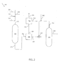
FIG. 2 is a schematic diagram of a process for the gasification of a whole crude oil feedstock in accordance with the present invention. - The integrated process for the production of a syngas and/or hydrogen by the partial oxidation of a whole crude oil feedstock in a membrane wall gasification reactor and the associated steam turbine for production of electricity will be described with reference to the schematic diagram of
FIG. 2 . - The whole crude
oil gasification apparatus 200 includes a membranewall gasification reactor 210, aheat exchanger 220, aturbine 230 and a water-gasshift reaction vessel 240. Note that while the embodiment ofapparatus 200 described herein includes a water-gas shift reaction vessel to enhance the output of hydrogen by conversion of some or all of the carbon monoxide in the syngas, alternative embodiments similar toapparatus 200 can be practiced without the water-gas shift reaction vessel. - Membrane
wall gasification reactor 210 includes aninlet 211 in fluid communication with aconduit 213 for introducing a whole crude oil feedstock, aconduit 219 for introducing a controlled amount of solid ash-producing material, aconduit 215 for introducing a controlled amount of a pressurized stream of oxygen or an oxygen-containing gas, and aconduit 217 for introducing a controlled amount of steam. Membranewall gasification reactor 210 also includes anoutlet 212 for discharging hot raw syngas. -
Heat exchanger 220 includes aninlet 221 in fluid communication withoutlet 212 of the membranewall gasification reactor 210, anoutlet 222 for discharging steam, and anoutlet 224 for discharging cooled syngas. -
Turbine 230 includes aninlet 231 in fluid communication withoutlet 222 of theheat exchanger 220, and anelectrical conductor 232 for transmitting the electricity generated, and anoutlet 234 for low pressure stream. - The optional water-gas
shift reaction vessel 240 includes aninlet 241 in fluid communication withoutlet 224 of theheat exchanger 220 via a three-way valve 226 for receiving cooled syngas and aconduit 243 for introducing a controlled amount of steam, and anoutlet 242 for discharging the hydrogen rich shifted syngas product. - In the practice of the method of the invention, a whole crude oil feedstock is introduced as a pressurized feedstream via
conduit 213 into the membranewall gasification reactor 210 along with a predetermined amount of solid ash-producing material viaconduit 219, a predetermined amount of oxygen or an oxygen-containing gas viaconduit 215 and a predetermined amount of steam viaconduit 217. In order to optimize the operation of the reactor, an analysis of the carbon content of the crude oil feed should previously be obtained in order to determine the stoichiometric amount of oxygen that is to be introduced into the gasifier. One method of carbon analysis that is suited for this purpose is described in ASTM D-5291. - The whole crude oil and solid material are mixed, e.g., using an inline mixer, a flow-through mixing vessel or other known apparatus. The mixture of crude oil and solid ash-producing material is partially oxidized in the membrane
wall gasification reactor 210 to produce hydrogen and carbon monoxide in the form of a hot raw syngas. A particular advantage of the process of the invention is that no auxiliary or supplemental fuel gas is required in order to maintain the gasification temperature, since all of the fuel values required for combustion are present in the lighter components of the whole crude oil. The slag formed in the gasification reactor from the ash-producing material is also supplemented by some of the constituents that are present in the crude oil. - Hot raw syngas is discharged from
outlet 212 of the membranewall gasification reactor 210 and passed toinlet 221 of theheat exchanger 220 to produce a cooled syngas that is discharged viaoutlet 224. Steam discharged fromoutlet 222 of theheat exchanger 220 is passed toinlet 231 ofturbine 230 to produce electricity that is transmitted viaconductor outlet 232. Low pressure stream from the turbine is discharged viaoutlet 234. - In certain embodiments, at least a portion of the cooled syngas is conveyed via
valve 226 toinlet 241 of the water-gasshift reaction vessel 240 with steam introduced viaconduit 243. The steam can optionally be derived from thesteam generator 220. Carbon monoxide is converted to hydrogen in the presence of steam through the water-gas shift reaction represented by CO+H2O → CO2+H2. The content of carbon monoxide is reduced to less than one mole% after the water-gas shift reaction. A mixture of hydrogen, carbon dioxide, unreacted carbon monoxide and other impurities is discharged viaoutlet 242 as shifted syngas. High purity hydrogen gas is optionally recovered by a process such as pressure swing adsorption (PSA), or by use of membranes, absorption, adsorption, or combinations thereof. - The feedstocks for the process described herein are whole crude oil boiling in the range of from 36°C to about 1500°C, or even as high as 2000°C. The upper value is estimated based on studies reported in the art and the presence of very high molecular weight compounds present in crude oil. See Katz, D.L. et al., "Predicting Phase Behavior of Condensate/Crude Oil Systems Using Methane Interaction Coefficients", Journal of Petroleum Technology, (1978), 1649 and Boduszynski, M. et al., "Oil & Gas Journal, Sept. 11, 1995 . The feedstock can be a light crude oil that contains from less than 10% to up to about 60% by weight of light fractions boiling in the range of from 36°C to 370°C. The feedstock can be a heavy bituminous crude oil that contains from less than 25% to up to about 90% by weight of light fractions boiling in the range of from 36°C to 565°C. The hydrogen content of the light fraction is typically in the range of from 12 to 16 w%.
- The addition of a solid ash-producing material to the whole crude oil reactor feed is required to produce enough molten ash to condense on the cooled reactor sidewall to form the protective coating of liquid slag. Although the whole crude oil contains some constituents that will produce molten ash particles upon combustion, the total volume of such ash-producing constituents present in the crude oil is not alone sufficient to produce a protective slag coating on the reactor walls. The solid ash-producing material can include natural and/or synthetic oxides. Suitable materials for forming the slag on the reactor walls are one or more oxides of elements from Groups IA-VA, IVB, VIIIB of the Periodic Table. Preferred compounds include one or more oxides containing Si, Al, Fe, Ca, Mg, P, K, Na, S and Ti. The oxides are of the type typically produced by the partial combustion of coal. The amount of sulfur present in heavy oils such as vacuum residues, bitumens, and in solids such as asphaltenes and coke is high and the oxides formed are solid sulfates or sulfites. The solid ash-producing material content can constitute from 2% to 10 w% of the whole crude oil, with lower values in the range being preferred.
- The solid ash-producing material is preferably in the form of finely divided particles that are free-flowing in a dry state. The particle size is sufficiently small to avoid any clogging of nozzles or other distribution means in the reactor. The particles should pass Tyler mesh size 35 screen. These particles can be introduced into the liquid feed sufficiently upstream of the membrane wall reactor to provide for their distribution throughout the flowing feed stream. In order to assure a sufficiently uniform mixing of the particles, the feed stream can be passed through an in-line mixer, or other devices that are known in the art to achieve the desired degree of mixing of a dry material in a liquid stream to which it is added.
- In other embodiments, the dry particulate material can be treated, e.g., by spraying, with surfactant, to facilitate mixing with the whole crude oil. In order to facilitate pumping and metering, the dry particulate material(s) can be premixed with a portion of the whole crude oil feed, or some other liquid hydrocarbon material in a separate mixing vessel and stored or directly withdrawn as needed and added as a concentrated solid/liquid mixture in the appropriate proportion to the whole crude oil feed to achieve the desired weight percentages of solid ash-producing material.
- In general, the operating conditions for the membrane wall gasification reactor include a temperature in the range of from 1200°C to 1800°C; a pressure in the range of from 30 bars to 100 bars; a mole ratio of oxygen-to-carbon content of the feedstock in the range of from 0.1:1 to 2:1, in certain embodiments from 0.5:1 to 2:1, and in further embodiments from 1:1 to 5:1; a mole ratio of steam-to-carbon content of the feedstock in the range of from 0.1:1 to 10:1, in certain embodiments from 0.1:1 to 2:1, and in further embodiments from 0.4:1 to 0.6:1.
- The properties of the syngas subjected to the water-gas shift reaction are a temperature in the range of from 150°C to 400°C; a pressure in the range of from 1 bar to 60 bars; and a mole ratio of water-to-carbon monoxide in the range of from 5:1 to 3:1.
- Distinct advantages are offered by the apparatus and processes described herein when compared to other whole crude oil processes. The present invention eliminates the cost related to the distillation of whole crude oil. Valuable syngas and/or hydrogen gas, process steam and electricity are efficiently produced for on-site refinery use. The process of the present invention can be practiced to particular advantage when hydrogen is needed for hydroprocessing and natural gas is not available. This is usually the case in refineries when full conversion is required to meet the demand for cleaner and lighter products, such as gasoline, jet fuel, and diesel transportation fuels.
- In this example based on modeling, a 1000 kg sample consisting of a mixture of 968.7 kg of whole crude oil containing 31.3 kg of finely divided solid ash material representing about 3 % by weight of the total liquid feed is introduced as a pressurized feedstock into a membrane wall gasification reactor. The gasification reactor is operated at 1045°C and 28 bars. The ratio of steam-to-carbon is 0.6:1 by weight. The ratio of oxygen-to-carbon is 1:0.85 by weight. The whole crude oil is partially oxidized to produce hydrogen and carbon monoxide which are recovered as a hot raw syngas and passed to a heat exchanger to generate steam. The cooled raw syngas is sent to a water-gas shift reaction vessel to increase the hydrogen yield. The water-gas shift reaction is conducted at 318°C and 1 bar. The mole ratio of steam-to-carbon monoxide is 3:1. The product yields are summarized in Table 1. As can be seen from Table 1, gasification of 968.7 kg of whole crude oil produces 256.2 kg of hydrogen gas.
Table 1 - Gasification Yields Stream Whole Crude Oil (via inlet 213) Oxygen (via conduit 215) Steam (via conduit 217) Raw Syngas (via outlet 224 and inlet 241)Steam (via conduit 243) Shifted Syngas (via outlet 242) Kg Kg Kg Kg Kg Kg Total Pitch (containing ash) 1000.0 Pitch (containing hydrocarbons) 968.7.0 Oxygen 1000.0 CH4 6.5 6.5 H2 137.3 256.2 CO 1738.8 86.9 CO2 371.9 2967.7 H2O 506.7 182.8 1521.5 642.4 H2S 28.6 28.6 COS 5.6 5.6 N2 2.5 2.5 Ar 0.0 0.0 NH3 0.0 0.1 Total 1000.0 35.0 506.7 2474.2 1521.5 3996.5 Material Balance Total 98.7 MB Oxygen 98.5 - The method and system of the present invention have been described above and with reference to the attached drawings; however, modifications derived from this description will be apparent to those of ordinary skill in the art and the scope of protection for the invention is to be determined by the claims that follow.
Claims (15)
- An integrated process for the gasification of a whole crude oil feedstock to produce a synthesis gas and electricity, the process comprising:a. introducing into a membrane wall gasification reactor, as a feedstock, a mixture of whole crude oil and a solid ash-producing material capable of forming a protective slag coating on the sidewalls of the membrane wall gasification reactor, and a predetermined amount of oxygen and steam based on the carbon content of the feedstock;b. subjecting the mixture of whole crude oil and solid ash-producing material to partial oxidation to produce hydrogen and carbon monoxide in the form of a hot raw synthesis gas and a protective slag coating on the sidewalls of the membrane wall gasification reactor;c. passing the hot raw synthesis gas to a steam-generating heat exchanger to cool the hot raw synthesis gas and to produce steam;d. introducing the steam from the heat exchanger into a turbine to produce electricity; ande. recovering the cooled synthesis gas.
- The process of claim 1, wherein the solid ash-producing material is in the form of finely divided particles and is mixed with the whole crude oil and constitutes 2% to 5% by weight of the total weight of the whole crude oil feedstock.
- The process of claim 1, wherein the solid ash producing material is selected from the group consisting of natural and synthetic oxides of Si, Al, Fe, Ca, Mg, P, K, Na, S, and Ti and mixtures thereof.
- The process of claim 1, wherein the whole crude oil contains from 1 to 60 w% of light fractions boiling in the range of from 36°C to 370°C.
- The process of claim 1, wherein the whole crude oil contains from 1 to 10 w% of light fractions boiling in the range of from 36°C to 370°C.
- The process of claim 1, wherein the whole crude oil contains from 1 to 90 w% of light fractions boiling in the range of from 36°C to 565°C.
- The process of claim 1, wherein the whole crude oil contains from 1 to 25 w% of light fractions boiling in the range of from 36°C to 565°C.
- The process of claims 4-7, wherein the hydrogen content of the light fraction is in the range of from 12 to 16 w%.
- The process of claim 1, wherein the operating temperature of the gasification reactor is in the range of from 1200°C to 1800°C.
- The process of claim 1, wherein the mole ratio of oxygen-to-carbon in the gasification reactor is in the range of from 0.5:1 to 10:1.
- The process of claim 1, wherein the mole ratio of oxygen-to-carbon in the gasification reactor is in the range of from 1:1 to 2:1.
- The process of claim 1, wherein the mole ratio of steam-to-carbon in the gasification reactor is in the range of from 0.1:1 to 10:1 by weight.
- The process of claim 12, wherein the mole ratio of steam-to-carbon in the gasification reactor is in the range of from 0.5:1 to 1:1 by weight.
- The process of claim 1, further comprising subjecting the cooled syngas from step (e) to a water-gas shift reaction with a predetermined amount of steam, and recovering a mixture of hydrogen and carbon dioxide.
- The process of claim 14, wherein the mole ratio of water-to-carbon monoxide in the water-gas shift reaction vessel is in the range of from 5:1 to 3:1.
Applications Claiming Priority (2)
| Application Number | Priority Date | Filing Date | Title |
|---|---|---|---|
| US201261616179P | 2012-03-27 | 2012-03-27 | |
| PCT/US2013/033489 WO2013148503A1 (en) | 2012-03-27 | 2013-03-22 | Integrated process for the gasification of whole crude oil in a membrane wall gasifier and power generation |
Publications (2)
| Publication Number | Publication Date |
|---|---|
| EP2830992A1 EP2830992A1 (en) | 2015-02-04 |
| EP2830992B1 true EP2830992B1 (en) | 2017-05-10 |
Family
ID=48096239
Family Applications (1)
| Application Number | Title | Priority Date | Filing Date |
|---|---|---|---|
| EP13716566.8A Active EP2830992B1 (en) | 2012-03-27 | 2013-03-22 | Integrated process for the gasification of whole crude oil in a membrane wall gasifier and power generation |
Country Status (8)
| Country | Link |
|---|---|
| US (1) | US8974701B2 (en) |
| EP (1) | EP2830992B1 (en) |
| JP (1) | JP6018289B2 (en) |
| KR (1) | KR101571259B1 (en) |
| CN (1) | CN104302574B (en) |
| ES (1) | ES2633169T3 (en) |
| SG (1) | SG11201406088WA (en) |
| WO (1) | WO2013148503A1 (en) |
Families Citing this family (1)
| Publication number | Priority date | Publication date | Assignee | Title |
|---|---|---|---|---|
| US11732204B2 (en) | 2019-11-04 | 2023-08-22 | Saudi Arabian Oil Company | Syngas production and recovery of active phase metals from gasifier slag containing spent catalyst |
Family Cites Families (18)
| Publication number | Priority date | Publication date | Assignee | Title |
|---|---|---|---|---|
| US4099383A (en) * | 1976-06-21 | 1978-07-11 | Texaco Inc. | Partial oxidation process |
| JPS6054884B2 (en) * | 1977-11-29 | 1985-12-02 | テキサコ・テイベロツプメント・コ−ポレ−シヨン | Method for producing mixed gas |
| DE3667180D1 (en) * | 1985-06-27 | 1990-01-04 | Texaco Development Corp | PARTIAL OXIDATION METHOD. |
| US4668428A (en) * | 1985-06-27 | 1987-05-26 | Texaco Inc. | Partial oxidation process |
| US4851151A (en) * | 1988-05-06 | 1989-07-25 | Texaco Inc. | Process for production of synthesis gas with reduced sulfur content |
| US5851381A (en) * | 1990-12-07 | 1998-12-22 | Idemitsu Kosan Co., Ltd. | Method of refining crude oil |
| EP1349903B1 (en) * | 2001-01-10 | 2011-10-05 | Shell Internationale Research Maatschappij B.V. | Process for the production of thermally converted light products and electricity |
| US20020174603A1 (en) * | 2001-03-23 | 2002-11-28 | Shabbir Ahmed | Method for generating hydrogen for fuel cells |
| US7261751B2 (en) * | 2004-08-06 | 2007-08-28 | Conocophillips Company | Synthesis gas process comprising partial oxidation using controlled and optimized temperature profile |
| US7540893B2 (en) * | 2005-12-06 | 2009-06-02 | General Electric Company | System and method for producing synthesis gas |
| US20070245736A1 (en) * | 2006-04-25 | 2007-10-25 | Eastman Chemical Company | Process for superheated steam |
| US7722690B2 (en) * | 2006-09-29 | 2010-05-25 | Kellogg Brown & Root Llc | Methods for producing synthesis gas |
| US20080190026A1 (en) * | 2006-12-01 | 2008-08-14 | De Jong Johannes Cornelis | Process to prepare a mixture of hydrogen and carbon monoxide from a liquid hydrocarbon feedstock containing a certain amount of ash |
| AU2008327916B2 (en) * | 2007-11-20 | 2011-07-28 | Shell Internationale Research Maatschappij B.V. | Process for producing a purified synthesis gas stream |
| ITRM20100216A1 (en) * | 2010-05-04 | 2011-11-05 | Technip Kti Spa | "PROCESS FOR THE PRODUCTION OF SYNTHESIS AND HYDROGEN GAS FROM LIQUID HYDROCARBONS, GASEOUS HYDROCARBONS AND / OR OXYGENATED COMPOUNDS ALSO ARISING FROM BIOMASS THROUGH NON-INTEGRATED MEMBRANE REACTOR" |
| US8377154B2 (en) * | 2010-05-18 | 2013-02-19 | Kellogg Brown & Root Llc | Gasification system and process for maximizing production of syngas and syngas-derived products |
| US8863518B2 (en) * | 2010-09-27 | 2014-10-21 | Saudi Arabian Oil Company | Process for the gasification of waste tires with residual oil |
| US9234146B2 (en) * | 2011-07-27 | 2016-01-12 | Saudi Arabian Oil Company | Process for the gasification of heavy residual oil with particulate coke from a delayed coking unit |
-
2013
- 2013-03-13 US US13/801,364 patent/US8974701B2/en active Active
- 2013-03-22 SG SG11201406088WA patent/SG11201406088WA/en unknown
- 2013-03-22 EP EP13716566.8A patent/EP2830992B1/en active Active
- 2013-03-22 ES ES13716566.8T patent/ES2633169T3/en active Active
- 2013-03-22 KR KR1020147024166A patent/KR101571259B1/en active IP Right Grant
- 2013-03-22 JP JP2015503415A patent/JP6018289B2/en not_active Expired - Fee Related
- 2013-03-22 CN CN201380015519.0A patent/CN104302574B/en active Active
- 2013-03-22 WO PCT/US2013/033489 patent/WO2013148503A1/en active Application Filing
Also Published As
| Publication number | Publication date |
|---|---|
| CN104302574A (en) | 2015-01-21 |
| WO2013148503A1 (en) | 2013-10-03 |
| KR20150001724A (en) | 2015-01-06 |
| JP2015514665A (en) | 2015-05-21 |
| US8974701B2 (en) | 2015-03-10 |
| CN104302574B (en) | 2017-03-08 |
| SG11201406088WA (en) | 2014-11-27 |
| ES2633169T3 (en) | 2017-09-19 |
| KR101571259B1 (en) | 2015-11-23 |
| JP6018289B2 (en) | 2016-11-02 |
| WO2013148503A8 (en) | 2014-08-14 |
| EP2830992A1 (en) | 2015-02-04 |
| US20130256601A1 (en) | 2013-10-03 |
Similar Documents
| Publication | Publication Date | Title |
|---|---|---|
| US9359917B2 (en) | Gasification of heavy residue with solid catalyst from slurry hydrocracking process | |
| US10422046B2 (en) | Hydrogen production from an integrated electrolysis cell and hydrocarbon gasification reactor | |
| EP2737031B1 (en) | Process for the gasification of heavy residual oil with particulate coke from a delayed coking unit | |
| EP2737268B1 (en) | Production of synthesis gas from solvent deasphalting process bottoms in a membrane wall gasification reactor | |
| KR101644760B1 (en) | Two stage gasification with dual quench | |
| JP2014521581A5 (en) | ||
| US11148948B2 (en) | Gasification of disulfide oil to produce hydrogen and carbon monoxide (syngas) | |
| EP2830992B1 (en) | Integrated process for the gasification of whole crude oil in a membrane wall gasifier and power generation |
Legal Events
| Date | Code | Title | Description |
|---|---|---|---|
| PUAI | Public reference made under article 153(3) epc to a published international application that has entered the european phase |
Free format text: ORIGINAL CODE: 0009012 |
|
| 17P | Request for examination filed |
Effective date: 20140827 |
|
| AK | Designated contracting states |
Kind code of ref document: A1 Designated state(s): AL AT BE BG CH CY CZ DE DK EE ES FI FR GB GR HR HU IE IS IT LI LT LU LV MC MK MT NL NO PL PT RO RS SE SI SK SM TR |
|
| AX | Request for extension of the european patent |
Extension state: BA ME |
|
| RIN1 | Information on inventor provided before grant (corrected) |
Inventor name: BALLAGUET, JEAN-PIERRE Inventor name: KOSEOGLU, OMER REFA |
|
| DAX | Request for extension of the european patent (deleted) | ||
| GRAP | Despatch of communication of intention to grant a patent |
Free format text: ORIGINAL CODE: EPIDOSNIGR1 |
|
| RIC1 | Information provided on ipc code assigned before grant |
Ipc: C10J 3/74 20060101ALI20161122BHEP Ipc: C10K 3/04 20060101ALI20161122BHEP Ipc: C01B 3/36 20060101AFI20161122BHEP Ipc: C10J 3/48 20060101ALI20161122BHEP Ipc: C10J 3/86 20060101ALI20161122BHEP Ipc: C01B 3/48 20060101ALI20161122BHEP Ipc: C10K 1/00 20060101ALI20161122BHEP Ipc: F02C 3/28 20060101ALI20161122BHEP |
|
| INTG | Intention to grant announced |
Effective date: 20161219 |
|
| GRAS | Grant fee paid |
Free format text: ORIGINAL CODE: EPIDOSNIGR3 |
|
| GRAA | (expected) grant |
Free format text: ORIGINAL CODE: 0009210 |
|
| AK | Designated contracting states |
Kind code of ref document: B1 Designated state(s): AL AT BE BG CH CY CZ DE DK EE ES FI FR GB GR HR HU IE IS IT LI LT LU LV MC MK MT NL NO PL PT RO RS SE SI SK SM TR |
|
| REG | Reference to a national code |
Ref country code: GB Ref legal event code: FG4D |
|
| REG | Reference to a national code |
Ref country code: AT Ref legal event code: REF Ref document number: 892111 Country of ref document: AT Kind code of ref document: T Effective date: 20170515 Ref country code: CH Ref legal event code: EP |
|
| REG | Reference to a national code |
Ref country code: IE Ref legal event code: FG4D |
|
| REG | Reference to a national code |
Ref country code: DE Ref legal event code: R096 Ref document number: 602013020935 Country of ref document: DE |
|
| REG | Reference to a national code |
Ref country code: NL Ref legal event code: FP |
|
| REG | Reference to a national code |
Ref country code: ES Ref legal event code: FG2A Ref document number: 2633169 Country of ref document: ES Kind code of ref document: T3 Effective date: 20170919 |
|
| REG | Reference to a national code |
Ref country code: LT Ref legal event code: MG4D |
|
| REG | Reference to a national code |
Ref country code: NO Ref legal event code: T2 Effective date: 20170510 |
|
| REG | Reference to a national code |
Ref country code: AT Ref legal event code: MK05 Ref document number: 892111 Country of ref document: AT Kind code of ref document: T Effective date: 20170510 |
|
| PG25 | Lapsed in a contracting state [announced via postgrant information from national office to epo] |
Ref country code: HR Free format text: LAPSE BECAUSE OF FAILURE TO SUBMIT A TRANSLATION OF THE DESCRIPTION OR TO PAY THE FEE WITHIN THE PRESCRIBED TIME-LIMIT Effective date: 20170510 Ref country code: FI Free format text: LAPSE BECAUSE OF FAILURE TO SUBMIT A TRANSLATION OF THE DESCRIPTION OR TO PAY THE FEE WITHIN THE PRESCRIBED TIME-LIMIT Effective date: 20170510 Ref country code: GR Free format text: LAPSE BECAUSE OF FAILURE TO SUBMIT A TRANSLATION OF THE DESCRIPTION OR TO PAY THE FEE WITHIN THE PRESCRIBED TIME-LIMIT Effective date: 20170811 Ref country code: LT Free format text: LAPSE BECAUSE OF FAILURE TO SUBMIT A TRANSLATION OF THE DESCRIPTION OR TO PAY THE FEE WITHIN THE PRESCRIBED TIME-LIMIT Effective date: 20170510 Ref country code: AT Free format text: LAPSE BECAUSE OF FAILURE TO SUBMIT A TRANSLATION OF THE DESCRIPTION OR TO PAY THE FEE WITHIN THE PRESCRIBED TIME-LIMIT Effective date: 20170510 |
|
| PG25 | Lapsed in a contracting state [announced via postgrant information from national office to epo] |
Ref country code: BG Free format text: LAPSE BECAUSE OF FAILURE TO SUBMIT A TRANSLATION OF THE DESCRIPTION OR TO PAY THE FEE WITHIN THE PRESCRIBED TIME-LIMIT Effective date: 20170810 Ref country code: PL Free format text: LAPSE BECAUSE OF FAILURE TO SUBMIT A TRANSLATION OF THE DESCRIPTION OR TO PAY THE FEE WITHIN THE PRESCRIBED TIME-LIMIT Effective date: 20170510 Ref country code: SE Free format text: LAPSE BECAUSE OF FAILURE TO SUBMIT A TRANSLATION OF THE DESCRIPTION OR TO PAY THE FEE WITHIN THE PRESCRIBED TIME-LIMIT Effective date: 20170510 Ref country code: RS Free format text: LAPSE BECAUSE OF FAILURE TO SUBMIT A TRANSLATION OF THE DESCRIPTION OR TO PAY THE FEE WITHIN THE PRESCRIBED TIME-LIMIT Effective date: 20170510 Ref country code: LV Free format text: LAPSE BECAUSE OF FAILURE TO SUBMIT A TRANSLATION OF THE DESCRIPTION OR TO PAY THE FEE WITHIN THE PRESCRIBED TIME-LIMIT Effective date: 20170510 Ref country code: IS Free format text: LAPSE BECAUSE OF FAILURE TO SUBMIT A TRANSLATION OF THE DESCRIPTION OR TO PAY THE FEE WITHIN THE PRESCRIBED TIME-LIMIT Effective date: 20170910 |
|
| PG25 | Lapsed in a contracting state [announced via postgrant information from national office to epo] |
Ref country code: RO Free format text: LAPSE BECAUSE OF FAILURE TO SUBMIT A TRANSLATION OF THE DESCRIPTION OR TO PAY THE FEE WITHIN THE PRESCRIBED TIME-LIMIT Effective date: 20170510 Ref country code: EE Free format text: LAPSE BECAUSE OF FAILURE TO SUBMIT A TRANSLATION OF THE DESCRIPTION OR TO PAY THE FEE WITHIN THE PRESCRIBED TIME-LIMIT Effective date: 20170510 Ref country code: DK Free format text: LAPSE BECAUSE OF FAILURE TO SUBMIT A TRANSLATION OF THE DESCRIPTION OR TO PAY THE FEE WITHIN THE PRESCRIBED TIME-LIMIT Effective date: 20170510 Ref country code: CZ Free format text: LAPSE BECAUSE OF FAILURE TO SUBMIT A TRANSLATION OF THE DESCRIPTION OR TO PAY THE FEE WITHIN THE PRESCRIBED TIME-LIMIT Effective date: 20170510 Ref country code: SK Free format text: LAPSE BECAUSE OF FAILURE TO SUBMIT A TRANSLATION OF THE DESCRIPTION OR TO PAY THE FEE WITHIN THE PRESCRIBED TIME-LIMIT Effective date: 20170510 |
|
| REG | Reference to a national code |
Ref country code: DE Ref legal event code: R097 Ref document number: 602013020935 Country of ref document: DE |
|
| PG25 | Lapsed in a contracting state [announced via postgrant information from national office to epo] |
Ref country code: SM Free format text: LAPSE BECAUSE OF FAILURE TO SUBMIT A TRANSLATION OF THE DESCRIPTION OR TO PAY THE FEE WITHIN THE PRESCRIBED TIME-LIMIT Effective date: 20170510 |
|
| PLBE | No opposition filed within time limit |
Free format text: ORIGINAL CODE: 0009261 |
|
| STAA | Information on the status of an ep patent application or granted ep patent |
Free format text: STATUS: NO OPPOSITION FILED WITHIN TIME LIMIT |
|
| REG | Reference to a national code |
Ref country code: FR Ref legal event code: PLFP Year of fee payment: 6 |
|
| 26N | No opposition filed |
Effective date: 20180213 |
|
| PG25 | Lapsed in a contracting state [announced via postgrant information from national office to epo] |
Ref country code: SI Free format text: LAPSE BECAUSE OF FAILURE TO SUBMIT A TRANSLATION OF THE DESCRIPTION OR TO PAY THE FEE WITHIN THE PRESCRIBED TIME-LIMIT Effective date: 20170510 |
|
| REG | Reference to a national code |
Ref country code: CH Ref legal event code: PL |
|
| PG25 | Lapsed in a contracting state [announced via postgrant information from national office to epo] |
Ref country code: MC Free format text: LAPSE BECAUSE OF FAILURE TO SUBMIT A TRANSLATION OF THE DESCRIPTION OR TO PAY THE FEE WITHIN THE PRESCRIBED TIME-LIMIT Effective date: 20170510 |
|
| REG | Reference to a national code |
Ref country code: BE Ref legal event code: MM Effective date: 20180331 |
|
| REG | Reference to a national code |
Ref country code: IE Ref legal event code: MM4A |
|
| PG25 | Lapsed in a contracting state [announced via postgrant information from national office to epo] |
Ref country code: LU Free format text: LAPSE BECAUSE OF NON-PAYMENT OF DUE FEES Effective date: 20180322 |
|
| PG25 | Lapsed in a contracting state [announced via postgrant information from national office to epo] |
Ref country code: IE Free format text: LAPSE BECAUSE OF NON-PAYMENT OF DUE FEES Effective date: 20180322 |
|
| PG25 | Lapsed in a contracting state [announced via postgrant information from national office to epo] |
Ref country code: CH Free format text: LAPSE BECAUSE OF NON-PAYMENT OF DUE FEES Effective date: 20180331 Ref country code: BE Free format text: LAPSE BECAUSE OF NON-PAYMENT OF DUE FEES Effective date: 20180331 Ref country code: LI Free format text: LAPSE BECAUSE OF NON-PAYMENT OF DUE FEES Effective date: 20180331 |
|
| PG25 | Lapsed in a contracting state [announced via postgrant information from national office to epo] |
Ref country code: MT Free format text: LAPSE BECAUSE OF NON-PAYMENT OF DUE FEES Effective date: 20180322 |
|
| PG25 | Lapsed in a contracting state [announced via postgrant information from national office to epo] |
Ref country code: TR Free format text: LAPSE BECAUSE OF FAILURE TO SUBMIT A TRANSLATION OF THE DESCRIPTION OR TO PAY THE FEE WITHIN THE PRESCRIBED TIME-LIMIT Effective date: 20170510 |
|
| PG25 | Lapsed in a contracting state [announced via postgrant information from national office to epo] |
Ref country code: PT Free format text: LAPSE BECAUSE OF FAILURE TO SUBMIT A TRANSLATION OF THE DESCRIPTION OR TO PAY THE FEE WITHIN THE PRESCRIBED TIME-LIMIT Effective date: 20170510 Ref country code: HU Free format text: LAPSE BECAUSE OF FAILURE TO SUBMIT A TRANSLATION OF THE DESCRIPTION OR TO PAY THE FEE WITHIN THE PRESCRIBED TIME-LIMIT; INVALID AB INITIO Effective date: 20130322 |
|
| PG25 | Lapsed in a contracting state [announced via postgrant information from national office to epo] |
Ref country code: CY Free format text: LAPSE BECAUSE OF FAILURE TO SUBMIT A TRANSLATION OF THE DESCRIPTION OR TO PAY THE FEE WITHIN THE PRESCRIBED TIME-LIMIT Effective date: 20170510 Ref country code: MK Free format text: LAPSE BECAUSE OF NON-PAYMENT OF DUE FEES Effective date: 20170510 |
|
| PG25 | Lapsed in a contracting state [announced via postgrant information from national office to epo] |
Ref country code: AL Free format text: LAPSE BECAUSE OF FAILURE TO SUBMIT A TRANSLATION OF THE DESCRIPTION OR TO PAY THE FEE WITHIN THE PRESCRIBED TIME-LIMIT Effective date: 20170510 |
|
| PGFP | Annual fee paid to national office [announced via postgrant information from national office to epo] |
Ref country code: IT Payment date: 20210323 Year of fee payment: 9 Ref country code: NO Payment date: 20210329 Year of fee payment: 9 |
|
| PGFP | Annual fee paid to national office [announced via postgrant information from national office to epo] |
Ref country code: GB Payment date: 20210329 Year of fee payment: 9 |
|
| PGFP | Annual fee paid to national office [announced via postgrant information from national office to epo] |
Ref country code: ES Payment date: 20210405 Year of fee payment: 9 |
|
| REG | Reference to a national code |
Ref country code: NO Ref legal event code: MMEP |
|
| GBPC | Gb: european patent ceased through non-payment of renewal fee |
Effective date: 20220322 |
|
| PG25 | Lapsed in a contracting state [announced via postgrant information from national office to epo] |
Ref country code: NO Free format text: LAPSE BECAUSE OF NON-PAYMENT OF DUE FEES Effective date: 20220331 Ref country code: GB Free format text: LAPSE BECAUSE OF NON-PAYMENT OF DUE FEES Effective date: 20220322 |
|
| PGFP | Annual fee paid to national office [announced via postgrant information from national office to epo] |
Ref country code: NL Payment date: 20230221 Year of fee payment: 11 |
|
| PGFP | Annual fee paid to national office [announced via postgrant information from national office to epo] |
Ref country code: FR Payment date: 20230222 Year of fee payment: 11 |
|
| PG25 | Lapsed in a contracting state [announced via postgrant information from national office to epo] |
Ref country code: IT Free format text: LAPSE BECAUSE OF NON-PAYMENT OF DUE FEES Effective date: 20220322 |
|
| PGFP | Annual fee paid to national office [announced via postgrant information from national office to epo] |
Ref country code: DE Payment date: 20230221 Year of fee payment: 11 |
|
| REG | Reference to a national code |
Ref country code: ES Ref legal event code: FD2A Effective date: 20230602 |
|
| P01 | Opt-out of the competence of the unified patent court (upc) registered |
Effective date: 20230529 |
|
| PG25 | Lapsed in a contracting state [announced via postgrant information from national office to epo] |
Ref country code: ES Free format text: LAPSE BECAUSE OF NON-PAYMENT OF DUE FEES Effective date: 20220323 |