EP2830689B1 - Systems for providing respiratory therapy with varying flow rates - Google Patents
Systems for providing respiratory therapy with varying flow rates Download PDFInfo
- Publication number
- EP2830689B1 EP2830689B1 EP13768413.0A EP13768413A EP2830689B1 EP 2830689 B1 EP2830689 B1 EP 2830689B1 EP 13768413 A EP13768413 A EP 13768413A EP 2830689 B1 EP2830689 B1 EP 2830689B1
- Authority
- EP
- European Patent Office
- Prior art keywords
- flow
- breathing gas
- rate
- patient
- control device
- Prior art date
- Legal status (The legal status is an assumption and is not a legal conclusion. Google has not performed a legal analysis and makes no representation as to the accuracy of the status listed.)
- Active
Links
Images


Classifications
-
- A—HUMAN NECESSITIES
- A61—MEDICAL OR VETERINARY SCIENCE; HYGIENE
- A61M—DEVICES FOR INTRODUCING MEDIA INTO, OR ONTO, THE BODY; DEVICES FOR TRANSDUCING BODY MEDIA OR FOR TAKING MEDIA FROM THE BODY; DEVICES FOR PRODUCING OR ENDING SLEEP OR STUPOR
- A61M16/00—Devices for influencing the respiratory system of patients by gas treatment, e.g. ventilators; Tracheal tubes
- A61M16/0003—Accessories therefor, e.g. sensors, vibrators, negative pressure
-
- A—HUMAN NECESSITIES
- A61—MEDICAL OR VETERINARY SCIENCE; HYGIENE
- A61M—DEVICES FOR INTRODUCING MEDIA INTO, OR ONTO, THE BODY; DEVICES FOR TRANSDUCING BODY MEDIA OR FOR TAKING MEDIA FROM THE BODY; DEVICES FOR PRODUCING OR ENDING SLEEP OR STUPOR
- A61M16/00—Devices for influencing the respiratory system of patients by gas treatment, e.g. ventilators; Tracheal tubes
- A61M16/20—Valves specially adapted to medical respiratory devices
-
- A—HUMAN NECESSITIES
- A61—MEDICAL OR VETERINARY SCIENCE; HYGIENE
- A61M—DEVICES FOR INTRODUCING MEDIA INTO, OR ONTO, THE BODY; DEVICES FOR TRANSDUCING BODY MEDIA OR FOR TAKING MEDIA FROM THE BODY; DEVICES FOR PRODUCING OR ENDING SLEEP OR STUPOR
- A61M16/00—Devices for influencing the respiratory system of patients by gas treatment, e.g. ventilators; Tracheal tubes
- A61M16/0003—Accessories therefor, e.g. sensors, vibrators, negative pressure
- A61M16/0006—Accessories therefor, e.g. sensors, vibrators, negative pressure with means for creating vibrations in patients' airways
-
- A—HUMAN NECESSITIES
- A61—MEDICAL OR VETERINARY SCIENCE; HYGIENE
- A61M—DEVICES FOR INTRODUCING MEDIA INTO, OR ONTO, THE BODY; DEVICES FOR TRANSDUCING BODY MEDIA OR FOR TAKING MEDIA FROM THE BODY; DEVICES FOR PRODUCING OR ENDING SLEEP OR STUPOR
- A61M16/00—Devices for influencing the respiratory system of patients by gas treatment, e.g. ventilators; Tracheal tubes
- A61M16/0057—Pumps therefor
-
- A—HUMAN NECESSITIES
- A61—MEDICAL OR VETERINARY SCIENCE; HYGIENE
- A61M—DEVICES FOR INTRODUCING MEDIA INTO, OR ONTO, THE BODY; DEVICES FOR TRANSDUCING BODY MEDIA OR FOR TAKING MEDIA FROM THE BODY; DEVICES FOR PRODUCING OR ENDING SLEEP OR STUPOR
- A61M16/00—Devices for influencing the respiratory system of patients by gas treatment, e.g. ventilators; Tracheal tubes
- A61M16/0057—Pumps therefor
- A61M16/0066—Blowers or centrifugal pumps
- A61M16/0069—Blowers or centrifugal pumps the speed thereof being controlled by respiratory parameters, e.g. by inhalation
-
- A—HUMAN NECESSITIES
- A61—MEDICAL OR VETERINARY SCIENCE; HYGIENE
- A61M—DEVICES FOR INTRODUCING MEDIA INTO, OR ONTO, THE BODY; DEVICES FOR TRANSDUCING BODY MEDIA OR FOR TAKING MEDIA FROM THE BODY; DEVICES FOR PRODUCING OR ENDING SLEEP OR STUPOR
- A61M16/00—Devices for influencing the respiratory system of patients by gas treatment, e.g. ventilators; Tracheal tubes
- A61M16/08—Bellows; Connecting tubes ; Water traps; Patient circuits
- A61M16/0816—Joints or connectors
-
- A—HUMAN NECESSITIES
- A61—MEDICAL OR VETERINARY SCIENCE; HYGIENE
- A61M—DEVICES FOR INTRODUCING MEDIA INTO, OR ONTO, THE BODY; DEVICES FOR TRANSDUCING BODY MEDIA OR FOR TAKING MEDIA FROM THE BODY; DEVICES FOR PRODUCING OR ENDING SLEEP OR STUPOR
- A61M16/00—Devices for influencing the respiratory system of patients by gas treatment, e.g. ventilators; Tracheal tubes
- A61M16/10—Preparation of respiratory gases or vapours
-
- A—HUMAN NECESSITIES
- A61—MEDICAL OR VETERINARY SCIENCE; HYGIENE
- A61M—DEVICES FOR INTRODUCING MEDIA INTO, OR ONTO, THE BODY; DEVICES FOR TRANSDUCING BODY MEDIA OR FOR TAKING MEDIA FROM THE BODY; DEVICES FOR PRODUCING OR ENDING SLEEP OR STUPOR
- A61M16/00—Devices for influencing the respiratory system of patients by gas treatment, e.g. ventilators; Tracheal tubes
- A61M16/10—Preparation of respiratory gases or vapours
- A61M16/1075—Preparation of respiratory gases or vapours by influencing the temperature
-
- A—HUMAN NECESSITIES
- A61—MEDICAL OR VETERINARY SCIENCE; HYGIENE
- A61M—DEVICES FOR INTRODUCING MEDIA INTO, OR ONTO, THE BODY; DEVICES FOR TRANSDUCING BODY MEDIA OR FOR TAKING MEDIA FROM THE BODY; DEVICES FOR PRODUCING OR ENDING SLEEP OR STUPOR
- A61M16/00—Devices for influencing the respiratory system of patients by gas treatment, e.g. ventilators; Tracheal tubes
- A61M16/20—Valves specially adapted to medical respiratory devices
- A61M16/201—Controlled valves
- A61M16/202—Controlled valves electrically actuated
- A61M16/203—Proportional
- A61M16/204—Proportional used for inhalation control
-
- A—HUMAN NECESSITIES
- A61—MEDICAL OR VETERINARY SCIENCE; HYGIENE
- A61M—DEVICES FOR INTRODUCING MEDIA INTO, OR ONTO, THE BODY; DEVICES FOR TRANSDUCING BODY MEDIA OR FOR TAKING MEDIA FROM THE BODY; DEVICES FOR PRODUCING OR ENDING SLEEP OR STUPOR
- A61M16/00—Devices for influencing the respiratory system of patients by gas treatment, e.g. ventilators; Tracheal tubes
- A61M16/06—Respiratory or anaesthetic masks
- A61M16/0666—Nasal cannulas or tubing
-
- A—HUMAN NECESSITIES
- A61—MEDICAL OR VETERINARY SCIENCE; HYGIENE
- A61M—DEVICES FOR INTRODUCING MEDIA INTO, OR ONTO, THE BODY; DEVICES FOR TRANSDUCING BODY MEDIA OR FOR TAKING MEDIA FROM THE BODY; DEVICES FOR PRODUCING OR ENDING SLEEP OR STUPOR
- A61M2205/00—General characteristics of the apparatus
- A61M2205/33—Controlling, regulating or measuring
- A61M2205/3331—Pressure; Flow
- A61M2205/3334—Measuring or controlling the flow rate
-
- A—HUMAN NECESSITIES
- A61—MEDICAL OR VETERINARY SCIENCE; HYGIENE
- A61M—DEVICES FOR INTRODUCING MEDIA INTO, OR ONTO, THE BODY; DEVICES FOR TRANSDUCING BODY MEDIA OR FOR TAKING MEDIA FROM THE BODY; DEVICES FOR PRODUCING OR ENDING SLEEP OR STUPOR
- A61M2205/00—General characteristics of the apparatus
- A61M2205/33—Controlling, regulating or measuring
- A61M2205/3331—Pressure; Flow
- A61M2205/3337—Controlling, regulating pressure or flow by means of a valve by-passing a pump
Definitions
- the present invention relates generally to respiratory therapy, and more particularly to systems and methods for use in providing respiratory therapy with varying flow rates.
- Patients with respiratory ailments may be administered a supplemental flow of breathing gases, such as oxygen, for example, to aid in respiration.
- breathing gases are typically provided from a breathing gas supply, such as an oxygen tank, to a patient interface.
- the patient interface may be coupled to the breathing gas supply and in communication with a patient's nasal passages for delivery of the flow of breathing gas to the patient for nasal or oral inhalation.
- the flow of breathing gas provided to the patient may be selected based on the patient's inspiratory rate and the patient's respiratory ailment.
- a nasal cannula typically includes one or more nasal prongs, with each prong inserted into a respective nostril during use.
- the nasal cannula may optionally be retained during use by looping tubing attached to the cannula over the user's ears and drawing the tubing tight under the user's chin, or may be secured to the user by some other means.
- a conventional nasal cannula is described in U.S. Patent Application Publication No. US 2008/0121230 A1 .
- U.S. Patent No 4,637,385 describes a pulmonary ventilator system having a bellows assembly and a source of driving gas connected by a series branch including an electrically-controlled switching valve and a motor-controlled flow-rate-controlling valve.
- International Application No. WO 96/40337 A1 describes a breathing apparatus which allows automatic adjustment of the pressure support level to ensure adequate ventilation.
- U.S. Patent Application Publication No. 2006/260611 A1 describes a device for determining the change in the functional residual capacity.
- the present invention is directed to a system for providing respiratory therapy with varying flow rates according to independent claim 1.
- Embodiments of the present invention are directed to systems for providing respiratory therapy to a patient. These exemplary embodiments are usable to provide a flow of breathing gas to a patient at a varying rate of flow.
- the flow rates provided to the patient may be selected based on a number of factors, which are set forth in detail below.
- patient interface is intended to encompass any suitable apparatus for providing a flow of breathing gas to a patient for nasal and/or oral inhalation. Suitable patient interfaces will be known to one of ordinary skill in the art from the description herein.
- the disclosed embodiments of the present invention are usable to automatically vary the rate of a flow of breathing gas to a patient.
- the flow rate may vary between a predetermined maximum flow rate and a predetermined minimum flow rate
- the flow rate may be varied periodically at a rate slower than the patient's rate of breathing.
- the disclosed embodiments may be useful to vary the patient's airway pressure, and thereby change the patient's functional residual capacity (FRC).
- FRC functional residual capacity
- the disclosed embodiments may desirably improve alveolar ventilation.
- FIG. 1 illustrates an exemplary system 100 for providing respiratory therapy to a patient in accordance with aspects of the present invention.
- system 100 includes a source of breathing gas 110, a patient interface (such as nasal cannula 130), and a flow control device 150. Additional details of system 100 will be described herein.
- Source 110 provides breathing gas for inhalation by a patient.
- source 110 generates heated and humidified breathing gas for delivery to the patient.
- source 110 may include a delivery tube 112. Delivery tube 112 may be coupled to patient interface 130 in order to provide the heated and humidified gas from source 110 to the patient.
- Source 110 may be configured to provide breathing gas at flow rates between 4 and 8 liters per minute (Ipm) for infants, or between 25 and 40 Ipm for adults.
- Ipm liters per minute
- Suitable sources of heated and humidified gas will be known to one of ordinary skill in the art.
- source 110 may be the Vapotherm Flowrest System provided by Vapotherm, Inc. of Stevensville, Maryland, USA.
- Other suitable sources of breathing gas 110 will be known to one of ordinary skill in the art from the description herein.
- Nasal cannula 130 is configured to deliver the flow of breathing gas from source 110 to the patient.
- nasal cannula 130 comprises a first supply tube 132, a second supply tube 134, and a cannula body 136, as shown in FIG. 1 .
- Supply tubes 132 and 134 are elongated, hollow lumens.
- Supply tubes 132 and 134 are connected to a connector 138 in order to receive breathing gas from a breathing gas source.
- Connector 138 defines an inlet port and is configured to be connected to delivery tube 112 of source of breathing gas 110.
- supply tubes 132 and 134 enable fluid communication between source 110 and cannula body 136.
- Cannula body 136 is coupled to the ends of supply tubes 132 and 134 opposite connector 138. As shown in FIG. 1 , cannula body 136 includes nasal prongs 140 and 142 extending from cannula body 136. When nasal cannula 130 is secured to the patient, nasal prongs 140 and 142 are positioned within respective nares of the patient. Nasal prongs 140 and 142 define the outlet ports of nasal cannula 130, and deliver the flow of breathing gas received from supply tubes 132 and 134 to the patient. The shape and length of nasal prongs 140 and 142 may be selected to deliver pressure and/or facilitate purging of dead space, as would be understood by one of ordinary skill in the art.
- Flow control device 150 disposed within system 100 is in communication with the flow of breathing gas. As shown in FIG. 1 , flow control device 150 may be positioned within source of breathing gas 110. Alternatively, flow control device 150 may be coupled to or positioned within delivery tube 112 or nasal cannula 130.
- Flow control device 150 is configured to automatically change a rate of the flow of breathing gas to the patient.
- the term "automatically” is intended to convey that flow control device 150 is operable to change the rate of the flow of breathing gas without being caused to do so by an operator or patient of system 100. While flow control device 150 may be initially installed, prepared, or configured by such a user, during delivery of breathing gas to the patient, flow control device 150 operates to change the flow rate automatically, without direct instruction to perform such a change in flow rate.
- Flow control device 150 is configured to periodically vary the flow rate between the high flow rate and the low flow rate.
- the frequency of the period is lower than a frequency of breathing of the patient.
- the variance in flow rate provided by flow control device 150 is selected to be slower than the patient's rate of breathing.
- flow control device may vary the flow of breathing gas at a frequency of equal to or less than half of the breathing rate of the patient. This may be desirable so as to cause a change in functional residual capacity (FRC) of the patient, as opposed to an augmentation of tidal volume.
- Suitable frequencies for varying the flow rate between the high flow rate and the low flow rate may be chosen based on the patient's rate of breathing. For example, for infants, the changes frequency may be approximately 0.5 Hz (one cycle approximately every two seconds).
- a graph of flow rate over time to be provided by system 100 is illustrated in FIG. 2 .
- flow control device 150 is an oscillating fluidic flip valve.
- the valve is positioned in line with the flow of breathing gas.
- the valve includes an exhaust port for venting an excess flow of breathing gas provided by source 110.
- the valve may be configured to oscillate back and forth based on a fluid flip action, thereby allowing the patient to intermittently receive all and then some of the flow of breathing gas from source 110.
- Suitable valves for use as flow control device 150 include solenoid valves, auto pinch valves, or stepping motor valves. Other suitable valves will be known to one of ordinary skill in the art from the description herein.
- flow control device 150 comprises flow control circuitry coupled to source of breathing gas 110.
- the flow control circuitry is programmed to automatically change the rate of flow of breathing gas provided by source 110.
- the flow control circuitry may change the flow rate, for example, by adjusting the power to a flow generating element (e.g., a blower) within source 110.
- flow control circuitry may change the flow rate by adjusting a pressure of breathing gas within source 110, or adjusting the size of a breathing gas outlet of source 110 (e.g. with an adjustable/variable size orifice).
- flow control circuitry may change the flow rate by controlling the rate of a bypass flow to subtract from the main gas flow from source 110 (e.g., with a peristaltic or other pump).
- Suitable functions for flow control circuitry may be selected based on the type of source of breathing gas 110 used with system 100. Suitable processors and components for use as flow control circuitry will be known to one of ordinary skill in the art from the description herein.
- flow control device 150 is configured to maintain a first flow of breathing gas at a first flow rate for a first predetermined period of time, and then vary the flow rate in order to maintain a second flow of breathing gas at a second flow rate for a second predetermined period of time.
- the predetermined periods of time may be the same or different.
- the first and second flow rates may be maintained for approximately one second. It may be desirable that flow control device 150 change between the flow rates as quickly as possible (e.g., in one quarter second or less).
- the first flow rate may be a comparatively high flow rate (e.g., 8 lpm for infants, 40 Ipm for adults), and the second flow rate may be a comparatively low flow rate (e.g., 4 Ipm for infants, 25 Ipm for adults). It may be desirable that the low flow rate be less than approximately 50% of the high flow rate. It may also be desirable that the low flow rate still be higher than an inspiratory flow rate of the patient, in order to meet the patient's inspiratory flow needs and still have additional flow sufficient to purge the available anatomical dead space.
- System 100 may comprise multiple flow control devices 150, positioned at various points throughout system 100, in order to vary the flow of breathing gas to the patient.
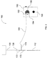
- FIG. 3 illustrates an exemplary apparatus 160 for varying the flow rate of breathing gas in accordance with aspects of the present invention.
- Apparatus 160 may be used in conjunction with the exemplary system 100 described above.
- apparatus 160 includes an adaptor 170, tubing 180, and a pump module 190. Additional details of apparatus 160 will be described herein.
- Adaptor 170 creates a bypass line in system 100.
- system 100 includes a source of breathing gas 110 that provides a flow of breathing gas to nasal cannula 130.
- adaptor 170 is a T-adaptor connected between the delivery tube 112 from the source of breathing gas 110 and the connector 138 of the nasal cannula 130.
- Adaptor 170 has a first branch 172 configured to provide at least a portion of the flow of breathing gas from source 110 to nasal cannula 130.
- Adaptor 170 has a second branch 174 configured to provide another portion of the flow of breathing gas (the "bypass flow") to pump module 180.
- the rate of the bypass flow is controlled by apparatus 160, as set forth below.
- Tubing 180 is connected to the second branch 174 of adaptor 180.
- Tubing 180 conveys the bypass flow of breathing gas from adaptor 170 to pump module 190.
- tubing 180 comprises a length of vinyl tubing. The length of tubing 180 may be selected based on the desired rate of the bypass flow of breathing gas, as set forth below.
- Pump module 190 is connected to tubing 180. Pump module 190 controls the rate of the bypass flow of breathing gas through the second branch 174 of adaptor 170.
- pump module 190 is a peristaltic pump having an inlet port 192 and an outlet port 194 and a roller 196.
- roller 196 rotates at a preselected frequency. As roller 196 rotates, it periodically closes and opens a pathway between input port 192 and outlet port 194. When the pathway is closed, airflow between input port 192 and outlet port 194 is blocked. This prevents any bypass flow from exiting adaptor 170 through second branch 174, and results in the high flow rate of breathing gas being delivered to the patient via nasal cannula 130. When the pathway is open, air flow between input port 192 and outlet 194 is enabled. This allows bypass flow to exit adaptor 170 through second branch 174, and results in the low flow rate of breathing gas being delivered to the patient.
- the rate of the bypass flow is determined based on the size of the orifices of adaptor 170 (and particularly of second branch 174), the diameter of tubing 180, and the length of tubing 180. It will be understood by one of ordinary skill in the art that these variables may be selected to generate the optimal bypass flow, i.e., the optimal difference between the high flow rate and the low flow rate provided to the patient.
- Pump module 190 includes adjustment means 198 for adjusting the frequency at which roller 196 rotates.
- the frequency for varying the flow rate between the high flow rate and the low flow rate corresponds to the frequency of rotation of roller 196. Accordingly, the frequency for varying the flow rate may be changed using adjustment means 198.
- adjustment means 198 is a turnable knob.
- alternative adjustment means 198 are envisioned, including buttons, switches, keypads, or any other similar structures.
- the configuration of the roller 196 may be selected to impact the ratio of time constants such that the patient is receiving full flow or partial flow.
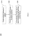
- FIG. 4 is a flowchart illustrating an exemplary method 200 for providing respiratory therapy to a patient in accordance with aspects of the present invention.
- Method 200 may be implemented using the exemplary system 100 described above.
- method 200 includes coupling a patient interface to the patient, providing a flow of breathing gas, and automatically changing a rate of the flow of breathing gas. Additional details of method 200 will be described herein with reference to system 100.
- a patient interface is coupled to the patient.
- nasal cannula 130 is secured to the patient.
- nasal prongs 140 and 142 are positioned within respective nares of the patient.
- Connector 138 of nasal cannula 130 may be coupled to delivery tube 112 of source of breathing gas 110 before or after nasal cannula 130 is secured to the patient.
- a flow of breathing gas is provided to the patient.
- source 110 provides a flow of breathing gas through the inlet port defined by connector 138.
- the flow of breathing gas passes through supply tubes 132 and 134 to cannula body 136.
- the flow of breathing gas is then delivered to the patient for inhalation via nasal prongs 140 and 142.
- a rate of the flow of breathing gas is automatically changed.
- flow control device 150 automatically changes the rate of the flow of breathing gas to the patient.
- step 230 may include maintaining a first flow of breathing gas at a first flow rate for a first predetermined period of time with flow control device 150, automatically varying the flow rate with flow control device 150, and maintaining a second flow of breathing gas at a second flow rate for a second predetermined period of time.
- the predetermined periods of time may be the same or different.
- the first flow rate may be a comparatively high flow rate (e.g., 8 Ipm for infants, 40 Ipm for adults), and the second flow rate may be a comparatively low flow rate (e.g.,4 lpm for infants, 25 Ipm for adults). As set forth above, it may be desirable that the low flow rate still be higher than an inspiratory flow rate of the patient.
- step 230 may include periodically varying the flow rate between the high flow rate and the low flow rate with flow control device 150.
- the frequency of the period may desirably be slower than a frequency of breathing of the patient.
Landscapes
- Health & Medical Sciences (AREA)
- Pulmonology (AREA)
- Life Sciences & Earth Sciences (AREA)
- Animal Behavior & Ethology (AREA)
- Anesthesiology (AREA)
- Biomedical Technology (AREA)
- Heart & Thoracic Surgery (AREA)
- Hematology (AREA)
- Emergency Medicine (AREA)
- Engineering & Computer Science (AREA)
- General Health & Medical Sciences (AREA)
- Public Health (AREA)
- Veterinary Medicine (AREA)
- Respiratory Apparatuses And Protective Means (AREA)
- Infusion, Injection, And Reservoir Apparatuses (AREA)
- Otolaryngology (AREA)
Description
- The present invention relates generally to respiratory therapy, and more particularly to systems and methods for use in providing respiratory therapy with varying flow rates.
- Patients with respiratory ailments may be administered a supplemental flow of breathing gases, such as oxygen, for example, to aid in respiration. These breathing gases are typically provided from a breathing gas supply, such as an oxygen tank, to a patient interface. The patient interface may be coupled to the breathing gas supply and in communication with a patient's nasal passages for delivery of the flow of breathing gas to the patient for nasal or oral inhalation. The flow of breathing gas provided to the patient may be selected based on the patient's inspiratory rate and the patient's respiratory ailment.
- One common patient interface is a nasal cannula. A nasal cannula typically includes one or more nasal prongs, with each prong inserted into a respective nostril during use. The nasal cannula may optionally be retained during use by looping tubing attached to the cannula over the user's ears and drawing the tubing tight under the user's chin, or may be secured to the user by some other means. A conventional nasal cannula is described in U.S. Patent Application Publication No.
US 2008/0121230 A1 . -
U.S. Patent No 4,637,385 describes a pulmonary ventilator system having a bellows assembly and a source of driving gas connected by a series branch including an electrically-controlled switching valve and a motor-controlled flow-rate-controlling valve. International Application No.WO 96/40337 A1 U.S. Patent Application Publication No. 2006/260611 A1 describes a device for determining the change in the functional residual capacity. - Improved systems and methods for respiratory therapy are desired.
- The present invention is directed to a system for providing respiratory therapy with varying flow rates according to independent claim 1.
- Further advantageous embodiments of the system are provided in the dependent claims.
- The invention is best understood from the following detailed description when read in connection with the accompanying drawings, with like elements having the same reference numerals. When a plurality of similar elements are present, a single reference numeral may be assigned to the plurality of similar elements with a small letter designation referring to specific elements. When referring to the elements collectively or to a non-specific one or more of the elements, the small letter designation may be dropped. According to common practice, the various features of the drawings are not drawn to scale, unless otherwise indicated. To the contrary, the dimensions of the various features may be expanded or reduced for clarity. Included in the drawings are the following figures:
-
FIG. 1 is a diagram illustrating an exemplary system for providing respiratory therapy to a patient in accordance with aspects of the present invention; -
FIG. 2 is a graph illustrating flow rate over time for an exemplary operation of the system ofFIG. 1 ; -
FIG. 3 is a diagram illustrating an exemplary apparatus for varying flow rate in accordance with aspects of the present invention; and -
FIG. 4 is a flowchart illustrating an exemplary method for providing respiratory therapy to a patient in accordance with aspects of the present invention. - Embodiments of the present invention are directed to systems for providing respiratory therapy to a patient. These exemplary embodiments are usable to provide a flow of breathing gas to a patient at a varying rate of flow. The flow rates provided to the patient may be selected based on a number of factors, which are set forth in detail below.
- While the exemplary embodiments are described herein with respect to a nasal cannula, it will be understood that other patient interfaces, such as breathing masks, may be used. As used herein, the term patient interface is intended to encompass any suitable apparatus for providing a flow of breathing gas to a patient for nasal and/or oral inhalation. Suitable patient interfaces will be known to one of ordinary skill in the art from the description herein.
- As a general overview, the disclosed embodiments of the present invention are usable to automatically vary the rate of a flow of breathing gas to a patient. The flow rate may vary between a predetermined maximum flow rate and a predetermined minimum flow rate The flow rate may be varied periodically at a rate slower than the patient's rate of breathing. By varying the flow rate in this way, the disclosed embodiments may be useful to vary the patient's airway pressure, and thereby change the patient's functional residual capacity (FRC). By way of a bellowing effect on the FRC, the disclosed embodiments may desirably improve alveolar ventilation.
- Referring now to the drawings,
FIG. 1 illustrates anexemplary system 100 for providing respiratory therapy to a patient in accordance with aspects of the present invention. Generally,system 100 includes a source ofbreathing gas 110, a patient interface (such as nasal cannula 130), and aflow control device 150. Additional details ofsystem 100 will be described herein. -
Source 110 provides breathing gas for inhalation by a patient. In an exemplary embodiment,source 110 generates heated and humidified breathing gas for delivery to the patient. As shown inFIG. 1 ,source 110 may include adelivery tube 112.Delivery tube 112 may be coupled topatient interface 130 in order to provide the heated and humidified gas fromsource 110 to the patient.Source 110 may be configured to provide breathing gas at flow rates between 4 and 8 liters per minute (Ipm) for infants, or between 25 and 40 Ipm for adults. Suitable sources of heated and humidified gas will be known to one of ordinary skill in the art. For example,source 110 may be the Vapotherm Flowrest System provided by Vapotherm, Inc. of Stevensville, Maryland, USA. Other suitable sources of breathinggas 110 will be known to one of ordinary skill in the art from the description herein. - Nasal
cannula 130 is configured to deliver the flow of breathing gas fromsource 110 to the patient. In an exemplary embodiment,nasal cannula 130 comprises afirst supply tube 132, asecond supply tube 134, and acannula body 136, as shown inFIG. 1 .Supply tubes Supply tubes connector 138 in order to receive breathing gas from a breathing gas source.Connector 138 defines an inlet port and is configured to be connected todelivery tube 112 of source ofbreathing gas 110. Thereby,supply tubes source 110 andcannula body 136. - Cannula
body 136 is coupled to the ends ofsupply tubes opposite connector 138. As shown inFIG. 1 ,cannula body 136 includesnasal prongs cannula body 136. Whennasal cannula 130 is secured to the patient,nasal prongs Nasal prongs nasal cannula 130, and deliver the flow of breathing gas received fromsupply tubes nasal prongs -
Flow control device 150 disposed withinsystem 100 is in communication with the flow of breathing gas. As shown inFIG. 1 ,flow control device 150 may be positioned within source of breathinggas 110. Alternatively,flow control device 150 may be coupled to or positioned withindelivery tube 112 ornasal cannula 130. -
Flow control device 150 is configured to automatically change a rate of the flow of breathing gas to the patient. As used herein, the term "automatically" is intended to convey thatflow control device 150 is operable to change the rate of the flow of breathing gas without being caused to do so by an operator or patient ofsystem 100. Whileflow control device 150 may be initially installed, prepared, or configured by such a user, during delivery of breathing gas to the patient,flow control device 150 operates to change the flow rate automatically, without direct instruction to perform such a change in flow rate. -
Flow control device 150 is configured to periodically vary the flow rate between the high flow rate and the low flow rate. The frequency of the period is lower than a frequency of breathing of the patient. In other words, the variance in flow rate provided byflow control device 150 is selected to be slower than the patient's rate of breathing. In one embodiment, flow control device may vary the flow of breathing gas at a frequency of equal to or less than half of the breathing rate of the patient. This may be desirable so as to cause a change in functional residual capacity (FRC) of the patient, as opposed to an augmentation of tidal volume. Suitable frequencies for varying the flow rate between the high flow rate and the low flow rate may be chosen based on the patient's rate of breathing. For example, for infants, the changes frequency may be approximately 0.5 Hz (one cycle approximately every two seconds). In accordance with the above-described operations offlow control device 150, a graph of flow rate over time to be provided bysystem 100 is illustrated inFIG. 2 . - In an exemplary embodiment,
flow control device 150 is an oscillating fluidic flip valve. The valve is positioned in line with the flow of breathing gas. The valve includes an exhaust port for venting an excess flow of breathing gas provided bysource 110. As would be understood by one of ordinary skill in the art, the valve may be configured to oscillate back and forth based on a fluid flip action, thereby allowing the patient to intermittently receive all and then some of the flow of breathing gas fromsource 110. Suitable valves for use asflow control device 150 include solenoid valves, auto pinch valves, or stepping motor valves. Other suitable valves will be known to one of ordinary skill in the art from the description herein. - In another exemplary embodiment,
flow control device 150 comprises flow control circuitry coupled to source of breathinggas 110. The flow control circuitry is programmed to automatically change the rate of flow of breathing gas provided bysource 110. The flow control circuitry may change the flow rate, for example, by adjusting the power to a flow generating element (e.g., a blower) withinsource 110. Alternatively, flow control circuitry may change the flow rate by adjusting a pressure of breathing gas withinsource 110, or adjusting the size of a breathing gas outlet of source 110 (e.g. with an adjustable/variable size orifice). Still further, flow control circuitry may change the flow rate by controlling the rate of a bypass flow to subtract from the main gas flow from source 110 (e.g., with a peristaltic or other pump). Suitable functions for flow control circuitry may be selected based on the type of source of breathinggas 110 used withsystem 100. Suitable processors and components for use as flow control circuitry will be known to one of ordinary skill in the art from the description herein. - In an exemplary operation,
flow control device 150 is configured to maintain a first flow of breathing gas at a first flow rate for a first predetermined period of time, and then vary the flow rate in order to maintain a second flow of breathing gas at a second flow rate for a second predetermined period of time. The predetermined periods of time may be the same or different. For example, when treating infants, the first and second flow rates may be maintained for approximately one second. It may be desirable thatflow control device 150 change between the flow rates as quickly as possible (e.g., in one quarter second or less). The first flow rate may be a comparatively high flow rate (e.g., 8 lpm for infants, 40 Ipm for adults), and the second flow rate may be a comparatively low flow rate (e.g., 4 Ipm for infants, 25 Ipm for adults). It may be desirable that the low flow rate be less than approximately 50% of the high flow rate. It may also be desirable that the low flow rate still be higher than an inspiratory flow rate of the patient, in order to meet the patient's inspiratory flow needs and still have additional flow sufficient to purge the available anatomical dead space. - While only a single
flow control device 150 described above, it will be understood by one of ordinary skill in the art thatsystem 100 is not so limited.System 100 may comprise multipleflow control devices 150, positioned at various points throughoutsystem 100, in order to vary the flow of breathing gas to the patient. -
FIG. 3 illustrates anexemplary apparatus 160 for varying the flow rate of breathing gas in accordance with aspects of the present invention.Apparatus 160 may be used in conjunction with theexemplary system 100 described above. Generally,apparatus 160 includes anadaptor 170,tubing 180, and apump module 190. Additional details ofapparatus 160 will be described herein. -
Adaptor 170 creates a bypass line insystem 100. As set forth above,system 100 includes a source of breathinggas 110 that provides a flow of breathing gas tonasal cannula 130. In an exemplary embodiment,adaptor 170 is a T-adaptor connected between thedelivery tube 112 from the source of breathinggas 110 and theconnector 138 of thenasal cannula 130.Adaptor 170 has afirst branch 172 configured to provide at least a portion of the flow of breathing gas fromsource 110 tonasal cannula 130.Adaptor 170 has asecond branch 174 configured to provide another portion of the flow of breathing gas (the "bypass flow") to pumpmodule 180. The rate of the bypass flow is controlled byapparatus 160, as set forth below. -
Tubing 180 is connected to thesecond branch 174 ofadaptor 180.Tubing 180 conveys the bypass flow of breathing gas fromadaptor 170 to pumpmodule 190. In an exemplary embodiment,tubing 180 comprises a length of vinyl tubing. The length oftubing 180 may be selected based on the desired rate of the bypass flow of breathing gas, as set forth below. -
Pump module 190 is connected totubing 180.Pump module 190 controls the rate of the bypass flow of breathing gas through thesecond branch 174 ofadaptor 170. In an exemplary embodiment,pump module 190 is a peristaltic pump having aninlet port 192 and anoutlet port 194 and aroller 196. - When
pump module 190 is activated, theroller 196 rotates at a preselected frequency. Asroller 196 rotates, it periodically closes and opens a pathway betweeninput port 192 andoutlet port 194. When the pathway is closed, airflow betweeninput port 192 andoutlet port 194 is blocked. This prevents any bypass flow from exitingadaptor 170 throughsecond branch 174, and results in the high flow rate of breathing gas being delivered to the patient vianasal cannula 130. When the pathway is open, air flow betweeninput port 192 andoutlet 194 is enabled. This allows bypass flow to exitadaptor 170 throughsecond branch 174, and results in the low flow rate of breathing gas being delivered to the patient. The rate of the bypass flow is determined based on the size of the orifices of adaptor 170 (and particularly of second branch 174), the diameter oftubing 180, and the length oftubing 180. It will be understood by one of ordinary skill in the art that these variables may be selected to generate the optimal bypass flow, i.e., the optimal difference between the high flow rate and the low flow rate provided to the patient. -
Pump module 190 includes adjustment means 198 for adjusting the frequency at whichroller 196 rotates. In this exemplary embodiment, the frequency for varying the flow rate between the high flow rate and the low flow rate corresponds to the frequency of rotation ofroller 196. Accordingly, the frequency for varying the flow rate may be changed using adjustment means 198. In an exemplary embodiment, adjustment means 198 is a turnable knob. However, alternative adjustment means 198 are envisioned, including buttons, switches, keypads, or any other similar structures. The configuration of theroller 196 may be selected to impact the ratio of time constants such that the patient is receiving full flow or partial flow. -
FIG. 4 is a flowchart illustrating anexemplary method 200 for providing respiratory therapy to a patient in accordance with aspects of the present invention.Method 200 may be implemented using theexemplary system 100 described above. Generally,method 200 includes coupling a patient interface to the patient, providing a flow of breathing gas, and automatically changing a rate of the flow of breathing gas. Additional details ofmethod 200 will be described herein with reference tosystem 100. - In
step 210, a patient interface is coupled to the patient. In an exemplary embodiment,nasal cannula 130 is secured to the patient. Whennasal cannula 130 is secured to the patient,nasal prongs Connector 138 ofnasal cannula 130 may be coupled todelivery tube 112 of source of breathinggas 110 before or afternasal cannula 130 is secured to the patient. - In
step 220, a flow of breathing gas is provided to the patient. In an exemplary embodiment,source 110 provides a flow of breathing gas through the inlet port defined byconnector 138. The flow of breathing gas passes throughsupply tubes cannula body 136. The flow of breathing gas is then delivered to the patient for inhalation vianasal prongs - In
step 230, a rate of the flow of breathing gas is automatically changed. In an exemplary embodiment,flow control device 150 automatically changes the rate of the flow of breathing gas to the patient. - For example, step 230 may include maintaining a first flow of breathing gas at a first flow rate for a first predetermined period of time with
flow control device 150, automatically varying the flow rate withflow control device 150, and maintaining a second flow of breathing gas at a second flow rate for a second predetermined period of time. The predetermined periods of time may be the same or different. The first flow rate may be a comparatively high flow rate (e.g., 8 Ipm for infants, 40 Ipm for adults), and the second flow rate may be a comparatively low flow rate (e.g.,4 lpm for infants, 25 Ipm for adults). As set forth above, it may be desirable that the low flow rate still be higher than an inspiratory flow rate of the patient. - For another example, step 230 may include periodically varying the flow rate between the high flow rate and the low flow rate with
flow control device 150. As set forth above, the frequency of the period may desirably be slower than a frequency of breathing of the patient. - Although the invention is illustrated and described herein with reference to specific embodiments, the invention is not intended to be limited to the details shown. Rather, various modifications may be made in the details within the scope of the claims.
Claims (10)
- A system (100) for providing respiratory therapy to a patient comprising:a source of breathing gas (110);a patient interface (130) comprising an inlet port (138) configured to receive a flow of breathing gas from the source of breathing gas and an outlet port (140, 142) configured to deliver the flow of breathing gas to the patient; anda flow control device (150) in communication with the flow of breathing gas, the flow control device configured to automatically change a rate of the flow of breathing gas, wherein the flow control device is configured to periodically vary the rate of the flow of breathing gas between a high flow rate and a low flow rate at a frequency slower than a frequency of breathing of the patient to change a functional residual capacity of the patient, wherein the high flow rate is higher than the low flow rate, and wherein the flow control device maintains the high flow rate and the low flow rate for predetermined periods of time prior to automatically changing the rate of the flow of breathing gas.
- The system of claim 1, wherein the patient interface comprises a nasal cannula.
- The system of claim 1, wherein the low flow rate is higher than an inspiratory flow rate of the patient.
- The system of claim 3, wherein the low flow rate is 4 liters per minute (lpm).
- The system of any preceding claim, wherein the flow control device comprises an apparatus (170) adapted to vary a rate of a bypass flow of gas from the source of breathing gas.
- The system of claim 5, wherein the flow control apparatus comprises a peristaltic pump (190) configured to periodically open and close a pathway (174), the pathway confining at least in part the bypass flow of gas.
- The system of claim 1, wherein the flow control device comprises an oscillating fluidic flip valve positioned in line with the flow of breathing gas.
- The system of claim 1, wherein the flow control device comprises flow control circuitry coupled to the source of breathing gas, the flow control circuitry programmed to change the rate of the flow of breathing gas from the source of breathing gas.
- The system of claim 1, wherein the flow control device varies the rate of the flow of breathing gas at a frequency that is slower than half the frequency of breathing of the patient.
- The system of claim 1, wherein the flow control device varies the rate of the flow of breathing gas at a frequency that is based on the frequency of breathing of the patient.
Applications Claiming Priority (2)
| Application Number | Priority Date | Filing Date | Title |
|---|---|---|---|
| US201261616600P | 2012-03-28 | 2012-03-28 | |
| PCT/US2013/033982 WO2013148754A1 (en) | 2012-03-28 | 2013-03-27 | Systems and methods for providing respiratory therapy with varying flow rates |
Publications (3)
| Publication Number | Publication Date |
|---|---|
| EP2830689A1 EP2830689A1 (en) | 2015-02-04 |
| EP2830689A4 EP2830689A4 (en) | 2016-01-20 |
| EP2830689B1 true EP2830689B1 (en) | 2017-08-09 |
Family
ID=49261193
Family Applications (1)
| Application Number | Title | Priority Date | Filing Date |
|---|---|---|---|
| EP13768413.0A Active EP2830689B1 (en) | 2012-03-28 | 2013-03-27 | Systems for providing respiratory therapy with varying flow rates |
Country Status (4)
| Country | Link |
|---|---|
| US (1) | US10213566B2 (en) |
| EP (1) | EP2830689B1 (en) |
| AU (1) | AU2013239822B2 (en) |
| WO (1) | WO2013148754A1 (en) |
Families Citing this family (11)
| Publication number | Priority date | Publication date | Assignee | Title |
|---|---|---|---|---|
| EP2113274B1 (en) | 2008-04-30 | 2016-04-27 | ResMed R&D Germany GmbH | Apparatus for controlled delivery of a breathing gas to the respiratory tracts of a user |
| GB2489184B (en) | 2009-12-23 | 2016-02-17 | Fisher & Paykel Healthcare Ltd | An interface |
| US11464928B2 (en) * | 2013-09-04 | 2022-10-11 | Fisher & Paykel Healthcare Limited | Flow therapy |
| EP3259000B1 (en) | 2015-03-31 | 2022-11-09 | Fisher & Paykel Healthcare Limited | Apparatus for high gas flow |
| AU2015230787B2 (en) * | 2015-03-31 | 2021-03-25 | Fisher & Paykel Healthcare Limited | Methods and apparatus for high gas flow |
| WO2016157106A1 (en) * | 2015-03-31 | 2016-10-06 | Fisher & Paykel Healthcare Limited | Methods and apparatus for oxygenation and/or co2 removal |
| GB2565942B (en) * | 2016-04-29 | 2022-06-01 | Fisher & Paykel Healthcare Ltd | Methods and apparatus for oxygenation and/or CO2 removal |
| WO2018084721A1 (en) | 2016-11-02 | 2018-05-11 | Fisher & Paykel Healthcare Limited | Method of driving a form of respiratory therapy |
| US12551642B2 (en) | 2017-06-30 | 2026-02-17 | Koninklijke Philips N.V. | Systems and methods for concurrent airway stabilization and pulmonary stretch receptor activation |
| EP3645095B1 (en) * | 2017-06-30 | 2021-11-03 | Koninklijke Philips N.V. | Systems for concurrent airway stabilization and pulmonary stretch receptor activation |
| US12544523B2 (en) | 2018-06-28 | 2026-02-10 | Koninklijke Philips N.V. | Systems and methods for concurrent airway stabilization and pulmonary stretch receptor activation |
Family Cites Families (18)
| Publication number | Priority date | Publication date | Assignee | Title |
|---|---|---|---|---|
| US3794026A (en) | 1970-07-29 | 1974-02-26 | H Jacobs | Ventilating apparatus embodying selective volume or pressure operation and catheter means for use therewith |
| US4637385A (en) * | 1986-01-13 | 1987-01-20 | Tibor Rusz | Pulmonary ventilator controller |
| US4838259A (en) * | 1986-01-27 | 1989-06-13 | Advanced Pulmonary Technologies, Inc. | Multi-frequency jet ventilation technique and apparatus |
| US5134995A (en) * | 1989-05-19 | 1992-08-04 | Puritan-Bennett Corporation | Inspiratory airway pressure system with admittance determining apparatus and method |
| US5148802B1 (en) * | 1989-09-22 | 1997-08-12 | Respironics Inc | Method and apparatus for maintaining airway patency to treat sleep apnea and other disorders |
| WO1996040337A1 (en) | 1995-06-07 | 1996-12-19 | Nellcor Puritan Bennett Incorporated | Pressure control for constant minute volume |
| AU4687600A (en) | 1999-04-27 | 2000-11-10 | Loma Linda University Medical Center | Device and method for the administration of oxygen |
| US7938114B2 (en) * | 2001-10-12 | 2011-05-10 | Ric Investments Llc | Auto-titration bi-level pressure support system and method of using same |
| AU2004261207B2 (en) | 2003-07-28 | 2011-02-17 | Salter Labs, Llc | Respiratory therapy system including a nasal cannula assembly |
| US20050092322A1 (en) * | 2003-11-05 | 2005-05-05 | Collins William L.Jr. | Cannula assembly and medical system employing a known carbon dioxide gas concentration |
| US7717110B2 (en) * | 2004-10-01 | 2010-05-18 | Ric Investments, Llc | Method and apparatus for treating Cheyne-Stokes respiration |
| DE102005022896B3 (en) * | 2005-05-18 | 2006-05-11 | Dräger Medical AG & Co. KG | Method for controlling respirator involves receiving measuring signals with the help of electrical impedance measuring instrument fitted with electrode application at test person |
| JP5356808B2 (en) * | 2005-06-14 | 2013-12-04 | レスメド・リミテッド | Method and apparatus for controlling mask leakage in CPAP treatment |
| US8171935B2 (en) * | 2006-11-15 | 2012-05-08 | Vapotherm, Inc. | Nasal cannula with reduced heat loss to reduce rainout |
| US20080295839A1 (en) * | 2007-06-01 | 2008-12-04 | Habashi Nader M | Ventilator Apparatus and System of Ventilation |
| CN102209569B (en) | 2008-09-10 | 2015-06-03 | 瑞思迈有限公司 | Improved Power Management in Respiratory Therapy Devices |
| DE102009047246A1 (en) * | 2008-12-01 | 2010-06-10 | Fisher & Paykel Healthcare Ltd., East Tamaki | nasal cannula |
| US8985106B2 (en) * | 2009-06-05 | 2015-03-24 | Resmed Limited | Methods and devices for the detection of hypopnoea |
-
2013
- 2013-03-27 US US14/388,680 patent/US10213566B2/en not_active Expired - Fee Related
- 2013-03-27 WO PCT/US2013/033982 patent/WO2013148754A1/en not_active Ceased
- 2013-03-27 AU AU2013239822A patent/AU2013239822B2/en not_active Ceased
- 2013-03-27 EP EP13768413.0A patent/EP2830689B1/en active Active
Non-Patent Citations (1)
| Title |
|---|
| None * |
Also Published As
| Publication number | Publication date |
|---|---|
| US20150059751A1 (en) | 2015-03-05 |
| EP2830689A1 (en) | 2015-02-04 |
| AU2013239822A1 (en) | 2014-10-16 |
| WO2013148754A1 (en) | 2013-10-03 |
| AU2013239822B2 (en) | 2017-07-20 |
| US10213566B2 (en) | 2019-02-26 |
| EP2830689A4 (en) | 2016-01-20 |
Similar Documents
| Publication | Publication Date | Title |
|---|---|---|
| US10213566B2 (en) | Systems and methods for providing respiratory therapy with varying flow rates | |
| US20250144359A1 (en) | Combination cpap and resuscitation systems and methods | |
| EP2037991B1 (en) | Ventilator adaptable for use with either a dual-limb or a single-limb circuit | |
| CN109803703B (en) | Anesthesia delivery and ventilation system | |
| US10960171B2 (en) | Breathing assistance apparatus | |
| AU2008326425B2 (en) | Patient interface assembly for respiratory therapy | |
| EP2945677B1 (en) | System for controlling airway gas parameters during high frequency positive pressure ventilation | |
| US11446454B2 (en) | Device for respiratory therapy | |
| AU5659500A (en) | Breathing assistance apparatus | |
| JP2013536705A (en) | Method and apparatus for preventing rainout | |
| JP2011519655A (en) | Exhaust assembly | |
| WO2007102866A2 (en) | Ventilator adaptable for use with either a dual-limb or a single-limb circuit | |
| JP2001276222A (en) | High-frequency oscillation type respirator | |
| CN209033458U (en) | Equipment for conveying heated and humidified oxygen and air mixtures | |
| JPH09183601A (en) | Oxygen-enriched air supply device | |
| JP2798259B2 (en) | Ventilator | |
| JPH09239033A (en) | Oxygen-enriched air supply device | |
| WO2021224894A1 (en) | Ventilator and method of ventilation | |
| JPH09257136A (en) | Selector valve and artificial respiration device using it |
Legal Events
| Date | Code | Title | Description |
|---|---|---|---|
| PUAI | Public reference made under article 153(3) epc to a published international application that has entered the european phase |
Free format text: ORIGINAL CODE: 0009012 |
|
| 17P | Request for examination filed |
Effective date: 20141027 |
|
| AK | Designated contracting states |
Kind code of ref document: A1 Designated state(s): AL AT BE BG CH CY CZ DE DK EE ES FI FR GB GR HR HU IE IS IT LI LT LU LV MC MK MT NL NO PL PT RO RS SE SI SK SM TR |
|
| AX | Request for extension of the european patent |
Extension state: BA ME |
|
| DAX | Request for extension of the european patent (deleted) | ||
| RA4 | Supplementary search report drawn up and despatched (corrected) |
Effective date: 20151221 |
|
| RIC1 | Information provided on ipc code assigned before grant |
Ipc: A61M 16/00 20060101AFI20151215BHEP Ipc: A61M 16/10 20060101ALI20151215BHEP |
|
| GRAP | Despatch of communication of intention to grant a patent |
Free format text: ORIGINAL CODE: EPIDOSNIGR1 |
|
| INTG | Intention to grant announced |
Effective date: 20170307 |
|
| GRAS | Grant fee paid |
Free format text: ORIGINAL CODE: EPIDOSNIGR3 |
|
| GRAA | (expected) grant |
Free format text: ORIGINAL CODE: 0009210 |
|
| AK | Designated contracting states |
Kind code of ref document: B1 Designated state(s): AL AT BE BG CH CY CZ DE DK EE ES FI FR GB GR HR HU IE IS IT LI LT LU LV MC MK MT NL NO PL PT RO RS SE SI SK SM TR |
|
| REG | Reference to a national code |
Ref country code: GB Ref legal event code: FG4D |
|
| REG | Reference to a national code |
Ref country code: CH Ref legal event code: EP Ref country code: AT Ref legal event code: REF Ref document number: 916150 Country of ref document: AT Kind code of ref document: T Effective date: 20170815 |
|
| REG | Reference to a national code |
Ref country code: IE Ref legal event code: FG4D |
|
| REG | Reference to a national code |
Ref country code: DE Ref legal event code: R096 Ref document number: 602013024828 Country of ref document: DE |
|
| RAP2 | Party data changed (patent owner data changed or rights of a patent transferred) |
Owner name: VAPOTHERM, INC. |
|
| REG | Reference to a national code |
Ref country code: NL Ref legal event code: FP |
|
| REG | Reference to a national code |
Ref country code: LT Ref legal event code: MG4D |
|
| REG | Reference to a national code |
Ref country code: AT Ref legal event code: MK05 Ref document number: 916150 Country of ref document: AT Kind code of ref document: T Effective date: 20170809 |
|
| PG25 | Lapsed in a contracting state [announced via postgrant information from national office to epo] |
Ref country code: HR Free format text: LAPSE BECAUSE OF FAILURE TO SUBMIT A TRANSLATION OF THE DESCRIPTION OR TO PAY THE FEE WITHIN THE PRESCRIBED TIME-LIMIT Effective date: 20170809 Ref country code: FI Free format text: LAPSE BECAUSE OF FAILURE TO SUBMIT A TRANSLATION OF THE DESCRIPTION OR TO PAY THE FEE WITHIN THE PRESCRIBED TIME-LIMIT Effective date: 20170809 Ref country code: LT Free format text: LAPSE BECAUSE OF FAILURE TO SUBMIT A TRANSLATION OF THE DESCRIPTION OR TO PAY THE FEE WITHIN THE PRESCRIBED TIME-LIMIT Effective date: 20170809 Ref country code: NO Free format text: LAPSE BECAUSE OF FAILURE TO SUBMIT A TRANSLATION OF THE DESCRIPTION OR TO PAY THE FEE WITHIN THE PRESCRIBED TIME-LIMIT Effective date: 20171109 Ref country code: AT Free format text: LAPSE BECAUSE OF FAILURE TO SUBMIT A TRANSLATION OF THE DESCRIPTION OR TO PAY THE FEE WITHIN THE PRESCRIBED TIME-LIMIT Effective date: 20170809 Ref country code: SE Free format text: LAPSE BECAUSE OF FAILURE TO SUBMIT A TRANSLATION OF THE DESCRIPTION OR TO PAY THE FEE WITHIN THE PRESCRIBED TIME-LIMIT Effective date: 20170809 |
|
| PG25 | Lapsed in a contracting state [announced via postgrant information from national office to epo] |
Ref country code: BG Free format text: LAPSE BECAUSE OF FAILURE TO SUBMIT A TRANSLATION OF THE DESCRIPTION OR TO PAY THE FEE WITHIN THE PRESCRIBED TIME-LIMIT Effective date: 20171109 Ref country code: LV Free format text: LAPSE BECAUSE OF FAILURE TO SUBMIT A TRANSLATION OF THE DESCRIPTION OR TO PAY THE FEE WITHIN THE PRESCRIBED TIME-LIMIT Effective date: 20170809 Ref country code: GR Free format text: LAPSE BECAUSE OF FAILURE TO SUBMIT A TRANSLATION OF THE DESCRIPTION OR TO PAY THE FEE WITHIN THE PRESCRIBED TIME-LIMIT Effective date: 20171110 Ref country code: ES Free format text: LAPSE BECAUSE OF FAILURE TO SUBMIT A TRANSLATION OF THE DESCRIPTION OR TO PAY THE FEE WITHIN THE PRESCRIBED TIME-LIMIT Effective date: 20170809 Ref country code: PL Free format text: LAPSE BECAUSE OF FAILURE TO SUBMIT A TRANSLATION OF THE DESCRIPTION OR TO PAY THE FEE WITHIN THE PRESCRIBED TIME-LIMIT Effective date: 20170809 Ref country code: IS Free format text: LAPSE BECAUSE OF FAILURE TO SUBMIT A TRANSLATION OF THE DESCRIPTION OR TO PAY THE FEE WITHIN THE PRESCRIBED TIME-LIMIT Effective date: 20171209 Ref country code: RS Free format text: LAPSE BECAUSE OF FAILURE TO SUBMIT A TRANSLATION OF THE DESCRIPTION OR TO PAY THE FEE WITHIN THE PRESCRIBED TIME-LIMIT Effective date: 20170809 |
|
| REG | Reference to a national code |
Ref country code: FR Ref legal event code: PLFP Year of fee payment: 6 |
|
| PG25 | Lapsed in a contracting state [announced via postgrant information from national office to epo] |
Ref country code: CZ Free format text: LAPSE BECAUSE OF FAILURE TO SUBMIT A TRANSLATION OF THE DESCRIPTION OR TO PAY THE FEE WITHIN THE PRESCRIBED TIME-LIMIT Effective date: 20170809 Ref country code: DK Free format text: LAPSE BECAUSE OF FAILURE TO SUBMIT A TRANSLATION OF THE DESCRIPTION OR TO PAY THE FEE WITHIN THE PRESCRIBED TIME-LIMIT Effective date: 20170809 Ref country code: RO Free format text: LAPSE BECAUSE OF FAILURE TO SUBMIT A TRANSLATION OF THE DESCRIPTION OR TO PAY THE FEE WITHIN THE PRESCRIBED TIME-LIMIT Effective date: 20170809 |
|
| RAP2 | Party data changed (patent owner data changed or rights of a patent transferred) |
Owner name: VAPOTHERM, INC. |
|
| REG | Reference to a national code |
Ref country code: DE Ref legal event code: R097 Ref document number: 602013024828 Country of ref document: DE |
|
| PG25 | Lapsed in a contracting state [announced via postgrant information from national office to epo] |
Ref country code: SM Free format text: LAPSE BECAUSE OF FAILURE TO SUBMIT A TRANSLATION OF THE DESCRIPTION OR TO PAY THE FEE WITHIN THE PRESCRIBED TIME-LIMIT Effective date: 20170809 Ref country code: EE Free format text: LAPSE BECAUSE OF FAILURE TO SUBMIT A TRANSLATION OF THE DESCRIPTION OR TO PAY THE FEE WITHIN THE PRESCRIBED TIME-LIMIT Effective date: 20170809 Ref country code: SK Free format text: LAPSE BECAUSE OF FAILURE TO SUBMIT A TRANSLATION OF THE DESCRIPTION OR TO PAY THE FEE WITHIN THE PRESCRIBED TIME-LIMIT Effective date: 20170809 |
|
| PLBE | No opposition filed within time limit |
Free format text: ORIGINAL CODE: 0009261 |
|
| STAA | Information on the status of an ep patent application or granted ep patent |
Free format text: STATUS: NO OPPOSITION FILED WITHIN TIME LIMIT |
|
| 26N | No opposition filed |
Effective date: 20180511 |
|
| PG25 | Lapsed in a contracting state [announced via postgrant information from national office to epo] |
Ref country code: SI Free format text: LAPSE BECAUSE OF FAILURE TO SUBMIT A TRANSLATION OF THE DESCRIPTION OR TO PAY THE FEE WITHIN THE PRESCRIBED TIME-LIMIT Effective date: 20170809 |
|
| REG | Reference to a national code |
Ref country code: CH Ref legal event code: PL |
|
| PG25 | Lapsed in a contracting state [announced via postgrant information from national office to epo] |
Ref country code: MC Free format text: LAPSE BECAUSE OF FAILURE TO SUBMIT A TRANSLATION OF THE DESCRIPTION OR TO PAY THE FEE WITHIN THE PRESCRIBED TIME-LIMIT Effective date: 20170809 |
|
| REG | Reference to a national code |
Ref country code: BE Ref legal event code: MM Effective date: 20180331 |
|
| REG | Reference to a national code |
Ref country code: IE Ref legal event code: MM4A |
|
| PG25 | Lapsed in a contracting state [announced via postgrant information from national office to epo] |
Ref country code: LU Free format text: LAPSE BECAUSE OF NON-PAYMENT OF DUE FEES Effective date: 20180327 |
|
| PG25 | Lapsed in a contracting state [announced via postgrant information from national office to epo] |
Ref country code: IE Free format text: LAPSE BECAUSE OF NON-PAYMENT OF DUE FEES Effective date: 20180327 |
|
| PG25 | Lapsed in a contracting state [announced via postgrant information from national office to epo] |
Ref country code: BE Free format text: LAPSE BECAUSE OF NON-PAYMENT OF DUE FEES Effective date: 20180331 Ref country code: LI Free format text: LAPSE BECAUSE OF NON-PAYMENT OF DUE FEES Effective date: 20180331 Ref country code: CH Free format text: LAPSE BECAUSE OF NON-PAYMENT OF DUE FEES Effective date: 20180331 |
|
| PG25 | Lapsed in a contracting state [announced via postgrant information from national office to epo] |
Ref country code: MT Free format text: LAPSE BECAUSE OF NON-PAYMENT OF DUE FEES Effective date: 20180327 |
|
| PG25 | Lapsed in a contracting state [announced via postgrant information from national office to epo] |
Ref country code: TR Free format text: LAPSE BECAUSE OF FAILURE TO SUBMIT A TRANSLATION OF THE DESCRIPTION OR TO PAY THE FEE WITHIN THE PRESCRIBED TIME-LIMIT Effective date: 20170809 |
|
| PG25 | Lapsed in a contracting state [announced via postgrant information from national office to epo] |
Ref country code: PT Free format text: LAPSE BECAUSE OF FAILURE TO SUBMIT A TRANSLATION OF THE DESCRIPTION OR TO PAY THE FEE WITHIN THE PRESCRIBED TIME-LIMIT Effective date: 20170809 Ref country code: HU Free format text: LAPSE BECAUSE OF FAILURE TO SUBMIT A TRANSLATION OF THE DESCRIPTION OR TO PAY THE FEE WITHIN THE PRESCRIBED TIME-LIMIT; INVALID AB INITIO Effective date: 20130327 |
|
| PG25 | Lapsed in a contracting state [announced via postgrant information from national office to epo] |
Ref country code: CY Free format text: LAPSE BECAUSE OF FAILURE TO SUBMIT A TRANSLATION OF THE DESCRIPTION OR TO PAY THE FEE WITHIN THE PRESCRIBED TIME-LIMIT Effective date: 20170809 Ref country code: MK Free format text: LAPSE BECAUSE OF NON-PAYMENT OF DUE FEES Effective date: 20170809 |
|
| PG25 | Lapsed in a contracting state [announced via postgrant information from national office to epo] |
Ref country code: AL Free format text: LAPSE BECAUSE OF FAILURE TO SUBMIT A TRANSLATION OF THE DESCRIPTION OR TO PAY THE FEE WITHIN THE PRESCRIBED TIME-LIMIT Effective date: 20170809 |
|
| PGFP | Annual fee paid to national office [announced via postgrant information from national office to epo] |
Ref country code: IT Payment date: 20230321 Year of fee payment: 11 |
|
| PGFP | Annual fee paid to national office [announced via postgrant information from national office to epo] |
Ref country code: NL Payment date: 20230326 Year of fee payment: 11 |
|
| REG | Reference to a national code |
Ref country code: NL Ref legal event code: MM Effective date: 20240401 |
|
| PG25 | Lapsed in a contracting state [announced via postgrant information from national office to epo] |
Ref country code: NL Free format text: LAPSE BECAUSE OF NON-PAYMENT OF DUE FEES Effective date: 20240401 |
|
| PG25 | Lapsed in a contracting state [announced via postgrant information from national office to epo] |
Ref country code: NL Free format text: LAPSE BECAUSE OF NON-PAYMENT OF DUE FEES Effective date: 20240401 |
|
| PG25 | Lapsed in a contracting state [announced via postgrant information from national office to epo] |
Ref country code: IT Free format text: LAPSE BECAUSE OF NON-PAYMENT OF DUE FEES Effective date: 20240327 |
|
| PGFP | Annual fee paid to national office [announced via postgrant information from national office to epo] |
Ref country code: GB Payment date: 20260324 Year of fee payment: 14 |
|
| PGFP | Annual fee paid to national office [announced via postgrant information from national office to epo] |
Ref country code: DE Payment date: 20260319 Year of fee payment: 14 |
|
| PGFP | Annual fee paid to national office [announced via postgrant information from national office to epo] |
Ref country code: FR Payment date: 20260320 Year of fee payment: 14 |