EP2830677B1 - Device for monitoring blood leakage from wounds - Google Patents
Device for monitoring blood leakage from wounds Download PDFInfo
- Publication number
- EP2830677B1 EP2830677B1 EP13767355.4A EP13767355A EP2830677B1 EP 2830677 B1 EP2830677 B1 EP 2830677B1 EP 13767355 A EP13767355 A EP 13767355A EP 2830677 B1 EP2830677 B1 EP 2830677B1
- Authority
- EP
- European Patent Office
- Prior art keywords
- optical fiber
- patient
- distal end
- connection
- unit
- Prior art date
- Legal status (The legal status is an assumption and is not a legal conclusion. Google has not performed a legal analysis and makes no representation as to the accuracy of the status listed.)
- Active
Links
- 239000008280 blood Substances 0.000 title claims description 32
- 210000004369 blood Anatomy 0.000 title claims description 32
- 238000012544 monitoring process Methods 0.000 title claims description 20
- 206010052428 Wound Diseases 0.000 title description 7
- 208000027418 Wounds and injury Diseases 0.000 title description 7
- 239000013307 optical fiber Substances 0.000 claims description 165
- 230000009471 action Effects 0.000 claims description 6
- 239000012790 adhesive layer Substances 0.000 claims description 6
- 238000003780 insertion Methods 0.000 claims description 4
- 230000037431 insertion Effects 0.000 claims description 4
- 239000013013 elastic material Substances 0.000 claims description 2
- 238000011179 visual inspection Methods 0.000 claims 1
- 239000000835 fiber Substances 0.000 description 21
- 238000012806 monitoring device Methods 0.000 description 14
- 238000011282 treatment Methods 0.000 description 14
- 230000007423 decrease Effects 0.000 description 11
- 230000002792 vascular Effects 0.000 description 11
- 239000012530 fluid Substances 0.000 description 10
- 230000003287 optical effect Effects 0.000 description 10
- 239000000463 material Substances 0.000 description 9
- 239000000853 adhesive Substances 0.000 description 6
- 230000001070 adhesive effect Effects 0.000 description 6
- 238000000502 dialysis Methods 0.000 description 6
- 210000004243 sweat Anatomy 0.000 description 5
- 238000003754 machining Methods 0.000 description 4
- 239000004033 plastic Substances 0.000 description 4
- 229920003023 plastic Polymers 0.000 description 4
- XLYOFNOQVPJJNP-UHFFFAOYSA-N water Substances O XLYOFNOQVPJJNP-UHFFFAOYSA-N 0.000 description 4
- 230000005540 biological transmission Effects 0.000 description 3
- 238000005520 cutting process Methods 0.000 description 3
- 230000000740 bleeding effect Effects 0.000 description 2
- 230000017531 blood circulation Effects 0.000 description 2
- 238000010276 construction Methods 0.000 description 2
- 230000003247 decreasing effect Effects 0.000 description 2
- 229920001971 elastomer Polymers 0.000 description 2
- 239000010410 layer Substances 0.000 description 2
- 238000004519 manufacturing process Methods 0.000 description 2
- 238000000034 method Methods 0.000 description 2
- 238000005498 polishing Methods 0.000 description 2
- 230000009467 reduction Effects 0.000 description 2
- 210000003462 vein Anatomy 0.000 description 2
- LFQSCWFLJHTTHZ-UHFFFAOYSA-N Ethanol Chemical compound CCO LFQSCWFLJHTTHZ-UHFFFAOYSA-N 0.000 description 1
- XUIMIQQOPSSXEZ-UHFFFAOYSA-N Silicon Chemical compound [Si] XUIMIQQOPSSXEZ-UHFFFAOYSA-N 0.000 description 1
- 239000002253 acid Substances 0.000 description 1
- 150000007513 acids Chemical class 0.000 description 1
- 239000012459 cleaning agent Substances 0.000 description 1
- 238000004891 communication Methods 0.000 description 1
- 230000000295 complement effect Effects 0.000 description 1
- 230000007812 deficiency Effects 0.000 description 1
- 238000001514 detection method Methods 0.000 description 1
- 239000000806 elastomer Substances 0.000 description 1
- 238000005516 engineering process Methods 0.000 description 1
- 238000002474 experimental method Methods 0.000 description 1
- 239000011521 glass Substances 0.000 description 1
- 238000001631 haemodialysis Methods 0.000 description 1
- 230000000322 hemodialysis Effects 0.000 description 1
- 230000001771 impaired effect Effects 0.000 description 1
- 238000007689 inspection Methods 0.000 description 1
- 230000007257 malfunction Effects 0.000 description 1
- 238000012986 modification Methods 0.000 description 1
- 230000004048 modification Effects 0.000 description 1
- 229920003229 poly(methyl methacrylate) Polymers 0.000 description 1
- 239000004926 polymethyl methacrylate Substances 0.000 description 1
- 230000000717 retained effect Effects 0.000 description 1
- 229910052710 silicon Inorganic materials 0.000 description 1
- 239000010703 silicon Substances 0.000 description 1
- 239000007779 soft material Substances 0.000 description 1
- 238000003860 storage Methods 0.000 description 1
- 238000012360 testing method Methods 0.000 description 1
- 230000007704 transition Effects 0.000 description 1
Images


Classifications
-
- A—HUMAN NECESSITIES
- A61—MEDICAL OR VETERINARY SCIENCE; HYGIENE
- A61B—DIAGNOSIS; SURGERY; IDENTIFICATION
- A61B5/00—Measuring for diagnostic purposes; Identification of persons
- A61B5/02—Detecting, measuring or recording pulse, heart rate, blood pressure or blood flow; Combined pulse/heart-rate/blood pressure determination; Evaluating a cardiovascular condition not otherwise provided for, e.g. using combinations of techniques provided for in this group with electrocardiography or electroauscultation; Heart catheters for measuring blood pressure
- A61B5/02042—Determining blood loss or bleeding, e.g. during a surgical procedure
-
- A—HUMAN NECESSITIES
- A61—MEDICAL OR VETERINARY SCIENCE; HYGIENE
- A61B—DIAGNOSIS; SURGERY; IDENTIFICATION
- A61B5/00—Measuring for diagnostic purposes; Identification of persons
- A61B5/68—Arrangements of detecting, measuring or recording means, e.g. sensors, in relation to patient
- A61B5/6801—Arrangements of detecting, measuring or recording means, e.g. sensors, in relation to patient specially adapted to be attached to or worn on the body surface
- A61B5/683—Means for maintaining contact with the body
- A61B5/6832—Means for maintaining contact with the body using adhesives
-
- A—HUMAN NECESSITIES
- A61—MEDICAL OR VETERINARY SCIENCE; HYGIENE
- A61B—DIAGNOSIS; SURGERY; IDENTIFICATION
- A61B5/00—Measuring for diagnostic purposes; Identification of persons
- A61B5/15—Devices for taking samples of blood
- A61B5/150007—Details
- A61B5/150954—Means for the detection of operative contact with patient, e.g. by temperature sensitive sensor
-
- A—HUMAN NECESSITIES
- A61—MEDICAL OR VETERINARY SCIENCE; HYGIENE
- A61B—DIAGNOSIS; SURGERY; IDENTIFICATION
- A61B5/00—Measuring for diagnostic purposes; Identification of persons
- A61B5/0059—Measuring for diagnostic purposes; Identification of persons using light, e.g. diagnosis by transillumination, diascopy, fluorescence
-
- A—HUMAN NECESSITIES
- A61—MEDICAL OR VETERINARY SCIENCE; HYGIENE
- A61B—DIAGNOSIS; SURGERY; IDENTIFICATION
- A61B5/00—Measuring for diagnostic purposes; Identification of persons
- A61B5/14—Devices for taking samples of blood ; Measuring characteristics of blood in vivo, e.g. gas concentration within the blood, pH-value of blood
-
- A—HUMAN NECESSITIES
- A61—MEDICAL OR VETERINARY SCIENCE; HYGIENE
- A61B—DIAGNOSIS; SURGERY; IDENTIFICATION
- A61B5/00—Measuring for diagnostic purposes; Identification of persons
- A61B5/15—Devices for taking samples of blood
- A61B5/150007—Details
- A61B5/150015—Source of blood
- A61B5/15003—Source of blood for venous or arterial blood
-
- A—HUMAN NECESSITIES
- A61—MEDICAL OR VETERINARY SCIENCE; HYGIENE
- A61B—DIAGNOSIS; SURGERY; IDENTIFICATION
- A61B5/00—Measuring for diagnostic purposes; Identification of persons
- A61B5/15—Devices for taking samples of blood
- A61B5/150007—Details
- A61B5/150961—Means for the detection of the presence or absence of a module, a component or an abnormal condition; detection of leaks
-
- A—HUMAN NECESSITIES
- A61—MEDICAL OR VETERINARY SCIENCE; HYGIENE
- A61B—DIAGNOSIS; SURGERY; IDENTIFICATION
- A61B5/00—Measuring for diagnostic purposes; Identification of persons
- A61B5/68—Arrangements of detecting, measuring or recording means, e.g. sensors, in relation to patient
- A61B5/6801—Arrangements of detecting, measuring or recording means, e.g. sensors, in relation to patient specially adapted to be attached to or worn on the body surface
- A61B5/683—Means for maintaining contact with the body
- A61B5/6832—Means for maintaining contact with the body using adhesives
- A61B5/6833—Adhesive patches
-
- A—HUMAN NECESSITIES
- A61—MEDICAL OR VETERINARY SCIENCE; HYGIENE
- A61M—DEVICES FOR INTRODUCING MEDIA INTO, OR ONTO, THE BODY; DEVICES FOR TRANSDUCING BODY MEDIA OR FOR TAKING MEDIA FROM THE BODY; DEVICES FOR PRODUCING OR ENDING SLEEP OR STUPOR
- A61M1/00—Suction or pumping devices for medical purposes; Devices for carrying-off, for treatment of, or for carrying-over, body-liquids; Drainage systems
- A61M1/36—Other treatment of blood in a by-pass of the natural circulatory system, e.g. temperature adaptation, irradiation ; Extra-corporeal blood circuits
- A61M1/3621—Extra-corporeal blood circuits
- A61M1/3653—Interfaces between patient blood circulation and extra-corporal blood circuit
- A61M1/3656—Monitoring patency or flow at connection sites; Detecting disconnections
-
- A—HUMAN NECESSITIES
- A61—MEDICAL OR VETERINARY SCIENCE; HYGIENE
- A61M—DEVICES FOR INTRODUCING MEDIA INTO, OR ONTO, THE BODY; DEVICES FOR TRANSDUCING BODY MEDIA OR FOR TAKING MEDIA FROM THE BODY; DEVICES FOR PRODUCING OR ENDING SLEEP OR STUPOR
- A61M5/00—Devices for bringing media into the body in a subcutaneous, intra-vascular or intramuscular way; Accessories therefor, e.g. filling or cleaning devices, arm-rests
- A61M5/14—Infusion devices, e.g. infusing by gravity; Blood infusion; Accessories therefor
- A61M5/168—Means for controlling media flow to the body or for metering media to the body, e.g. drip meters, counters ; Monitoring media flow to the body
- A61M5/16831—Monitoring, detecting, signalling or eliminating infusion flow anomalies
-
- A—HUMAN NECESSITIES
- A61—MEDICAL OR VETERINARY SCIENCE; HYGIENE
- A61B—DIAGNOSIS; SURGERY; IDENTIFICATION
- A61B2560/00—Constructional details of operational features of apparatus; Accessories for medical measuring apparatus
- A61B2560/04—Constructional details of apparatus
- A61B2560/0406—Constructional details of apparatus specially shaped apparatus housings
- A61B2560/0412—Low-profile patch shaped housings
-
- A—HUMAN NECESSITIES
- A61—MEDICAL OR VETERINARY SCIENCE; HYGIENE
- A61B—DIAGNOSIS; SURGERY; IDENTIFICATION
- A61B2562/00—Details of sensors; Constructional details of sensor housings or probes; Accessories for sensors
- A61B2562/02—Details of sensors specially adapted for in-vivo measurements
- A61B2562/0233—Special features of optical sensors or probes classified in A61B5/00
-
- A—HUMAN NECESSITIES
- A61—MEDICAL OR VETERINARY SCIENCE; HYGIENE
- A61B—DIAGNOSIS; SURGERY; IDENTIFICATION
- A61B2562/00—Details of sensors; Constructional details of sensor housings or probes; Accessories for sensors
- A61B2562/22—Arrangements of medical sensors with cables or leads; Connectors or couplings specifically adapted for medical sensors
- A61B2562/221—Arrangements of sensors with cables or leads, e.g. cable harnesses
- A61B2562/223—Optical cables therefor
-
- A—HUMAN NECESSITIES
- A61—MEDICAL OR VETERINARY SCIENCE; HYGIENE
- A61B—DIAGNOSIS; SURGERY; IDENTIFICATION
- A61B2562/00—Details of sensors; Constructional details of sensor housings or probes; Accessories for sensors
- A61B2562/22—Arrangements of medical sensors with cables or leads; Connectors or couplings specifically adapted for medical sensors
- A61B2562/225—Connectors or couplings
- A61B2562/228—Sensors with optical connectors
-
- A—HUMAN NECESSITIES
- A61—MEDICAL OR VETERINARY SCIENCE; HYGIENE
- A61B—DIAGNOSIS; SURGERY; IDENTIFICATION
- A61B2562/00—Details of sensors; Constructional details of sensor housings or probes; Accessories for sensors
- A61B2562/24—Hygienic packaging for medical sensors; Maintaining apparatus for sensor hygiene
- A61B2562/242—Packaging, i.e. for packaging the sensor or apparatus before use
-
- A—HUMAN NECESSITIES
- A61—MEDICAL OR VETERINARY SCIENCE; HYGIENE
- A61B—DIAGNOSIS; SURGERY; IDENTIFICATION
- A61B5/00—Measuring for diagnostic purposes; Identification of persons
- A61B5/15—Devices for taking samples of blood
- A61B5/150969—Low-profile devices which resemble patches or plasters, e.g. also allowing collection of blood samples for testing
-
- A—HUMAN NECESSITIES
- A61—MEDICAL OR VETERINARY SCIENCE; HYGIENE
- A61B—DIAGNOSIS; SURGERY; IDENTIFICATION
- A61B5/00—Measuring for diagnostic purposes; Identification of persons
- A61B5/15—Devices for taking samples of blood
- A61B5/157—Devices characterised by integrated means for measuring characteristics of blood
-
- A—HUMAN NECESSITIES
- A61—MEDICAL OR VETERINARY SCIENCE; HYGIENE
- A61B—DIAGNOSIS; SURGERY; IDENTIFICATION
- A61B5/00—Measuring for diagnostic purposes; Identification of persons
- A61B5/44—Detecting, measuring or recording for evaluating the integumentary system, e.g. skin, hair or nails
- A61B5/441—Skin evaluation, e.g. for skin disorder diagnosis
- A61B5/445—Evaluating skin irritation or skin trauma, e.g. rash, eczema, wound, bed sore
-
- A—HUMAN NECESSITIES
- A61—MEDICAL OR VETERINARY SCIENCE; HYGIENE
- A61B—DIAGNOSIS; SURGERY; IDENTIFICATION
- A61B5/00—Measuring for diagnostic purposes; Identification of persons
- A61B5/68—Arrangements of detecting, measuring or recording means, e.g. sensors, in relation to patient
- A61B5/6801—Arrangements of detecting, measuring or recording means, e.g. sensors, in relation to patient specially adapted to be attached to or worn on the body surface
- A61B5/683—Means for maintaining contact with the body
- A61B5/6832—Means for maintaining contact with the body using adhesives
- A61B5/68335—Means for maintaining contact with the body using adhesives including release sheets or liners
-
- A—HUMAN NECESSITIES
- A61—MEDICAL OR VETERINARY SCIENCE; HYGIENE
- A61F—FILTERS IMPLANTABLE INTO BLOOD VESSELS; PROSTHESES; DEVICES PROVIDING PATENCY TO, OR PREVENTING COLLAPSING OF, TUBULAR STRUCTURES OF THE BODY, e.g. STENTS; ORTHOPAEDIC, NURSING OR CONTRACEPTIVE DEVICES; FOMENTATION; TREATMENT OR PROTECTION OF EYES OR EARS; BANDAGES, DRESSINGS OR ABSORBENT PADS; FIRST-AID KITS
- A61F13/00—Bandages or dressings; Absorbent pads
- A61F13/15—Absorbent pads, e.g. sanitary towels, swabs or tampons for external or internal application to the body; Supporting or fastening means therefor; Tampon applicators
- A61F13/42—Absorbent pads, e.g. sanitary towels, swabs or tampons for external or internal application to the body; Supporting or fastening means therefor; Tampon applicators with wetness indicator or alarm
- A61F2013/424—Absorbent pads, e.g. sanitary towels, swabs or tampons for external or internal application to the body; Supporting or fastening means therefor; Tampon applicators with wetness indicator or alarm having an electronic device
-
- A—HUMAN NECESSITIES
- A61—MEDICAL OR VETERINARY SCIENCE; HYGIENE
- A61M—DEVICES FOR INTRODUCING MEDIA INTO, OR ONTO, THE BODY; DEVICES FOR TRANSDUCING BODY MEDIA OR FOR TAKING MEDIA FROM THE BODY; DEVICES FOR PRODUCING OR ENDING SLEEP OR STUPOR
- A61M2205/00—General characteristics of the apparatus
- A61M2205/15—Detection of leaks
-
- A—HUMAN NECESSITIES
- A61—MEDICAL OR VETERINARY SCIENCE; HYGIENE
- A61M—DEVICES FOR INTRODUCING MEDIA INTO, OR ONTO, THE BODY; DEVICES FOR TRANSDUCING BODY MEDIA OR FOR TAKING MEDIA FROM THE BODY; DEVICES FOR PRODUCING OR ENDING SLEEP OR STUPOR
- A61M2205/00—General characteristics of the apparatus
- A61M2205/33—Controlling, regulating or measuring
- A61M2205/3306—Optical measuring means
Definitions
- the present invention relates to a device for monitoring of blood leakage from wounds.
- One particular field is monitoring of vascular access of a patient during extracorporeal treatment, such as dialysis.
- WO2006/001759A1 issued to the assignee of the present invention, discloses a method and means for detection of blood leakage from wounds by means of an optical fiber.
- the optical fiber is arranged in a loop from a light source to a patch to be attached to the patient and back to a light detector.
- the light source and light detector are arranged in a monitoring device at a distance from the patch and may be attached to the arm of a patient.
- the loop comprises a sensor portion arranged at the patch and in which the optical fiber is bent with a small radius, so that the total internal reflection angle inside the optical fiber is approached or exceeded.
- a portion of the light transmitted through the optical fiber passes out through the sidewall of the optical fiber in the small radius sensor portion.
- the sensor portion is exposed to a fluid, such as water or blood, the portion of the light passing out through the sidewall of the optical fiber in the small radius sensor portion increases, which may be sensed by the light detector as a decrease in light intensity, which may trigger an alarm.
- the device according to WO2006/001759A1 operates well and is able to monitor for example a vascular access in an extracorporeal treatment, such as dialysis.
- the manufacturing costs of said device may be further decreased.
- the amount of surplus material during manufacturing may be reduced.
- the security of the connection of the patient device to the monitor may be improved.
- a reduction of costs and operation requires a new technology to be used.
- the patient portion should be sterile and is disposable.
- the monitoring unit including the light source and detector and further electronic circuits is reusable.
- a reduction of costs per treatment may be obtained by reducing the costs of the disposable patient portion.
- Another problem is relocation of the patch when the optical fiber is exposed to a force.
- the optical fiber may be influenced upon resulting in the fact that the patch is removed. This may remain unnoticed for a long time. When it is noticed, it is sometimes difficult to relocate the patch and it may be required to attach a new patch. If the relocation remains unnoticed, this is a safety risk.
- WO2008/036149A2 discloses a devices for visually confirming the positioning of a distal end portion of an illuminating device placed within a patient, and includes inserting a distal end portion of an illuminating device internally into a patient, emitting light from the distal end portion of the illuminating device, observing transillumination resulting from the light emitted from the distal end portion of the illuminating device that occurs on an external surface of the patient, and correlating the location of the observed transillumination on the external surface of the patient with an internal location of the patient that underlies the location of observed transillumination, to confirm positioning of the distal end portion of the illuminating device.
- an object of the present invention is to mitigate, alleviate or eliminate one or more of the above-identified deficiencies and disadvantages singly or in any combination.
- a patch is attached to the patient adjacent the site to be monitored, such as a vascular access of a dialysis patient.
- the patch comprises a compress for absorbing blood emitted from the vascular access, which is an indication of an alarm condition.
- a distal end of an optical fiber which may be shaped as a cone and is exposed to the surrounding atmosphere, which is air, inside the compress.
- the proximal end of the optical fiber is connected to a light transmitter and a photo detector. Light transmitted through the optical fiber towards the distal end is normally reflected back 180 degrees to the photo detector by total internal reflection at the distal end surface of the fiber. If blood reaches and is contacting the exposed conical surface of the optical fiber, the total internal reflection disappears at the contacting area and light passes out through the distal end of the fiber. Then, the signal level at the photo detector decreases, which may cause an alarm or an alert situation.
- the expression proximal and distal are as seen from the monitor side, which means that the distal end is closest to the needle, catheter or wound to be monitored for bleeding.
- Bleeding may occur if a venous needle of a vascular access is removed during treatment.
- blood is returned to the body via a venous needle.
- the blood flow may be about 200 to 500 ml/min. If the venous needle accidentally is removed from the vein, the returning blood flow passes out of the needle instead of being returned to the patient. If such a situation remains unnoticed for only 2 minutes, a life threatening condition develops.
- blood is emitted and may be detected adjacent the blood access location. Often, the venous needle is rapidly removed far away from the access site, for example down the floor.
- the venous needle will emit a sufficient amount of blood to be detected at the access site even at a rapid removal.
- the blood left at the access site is very small, only a droplet, and the bulk of the blood is discharged for example at the floor.
- blood may leak from the vein and out through the hole in the skin left by the venous needle, at least for a short time duration.
- blood is also removed from a patient via an arterial needle. If such an arterial needle is removed or dislocated, this is not particularly dangerous, since such a dislocation only results in that blood is not removed out to the extracorporeal circuit, which only results in that the desired treatment is not achieved.
- the arterial needle access can also be monitored by the present embodiments of the invention.
- other sites on the skin of a patient may be monitored for blood, such as a wound.
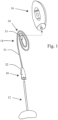
- Fig. 1 is a schematic overview of the components of a device 10 according to a first embodiment of the invention.
- the device 10 according to the first embodiment comprises a patient unit 12, a connection unit 14 and a monitor unit 16.
- the patient unit 12 is intended for attachment to a patient adjacent a wound or a vascular access to be monitored.
- the monitor unit 16 comprises electronic devices for monitoring the patient unit 12.
- the connection unit 14 is for connection of the patient unit 12 to the monitor unit 16.
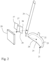
- the patient unit 12 is shown in more detail in Fig. 2 .
- the patient unit comprises a patch 21 of a flexible web material.
- the patch is covered by a plastics material 22 at the bottom side as seen in Fig. 2 , over at least a portion thereof, as shown by broken lines 23.
- the bottom side is facing away from the skin the patch is applied to the skin in a monitoring position.
- the upper side of the patch is partly covered by an adhesive layer 24 protected by a removable layer 25.
- the adhesive layer 24 becomes exposed and may attach the patch to the skin of a patient, for example adjacent a vascular access.
- the adhesive is dimensioned so that a specific removal force is required for removing the patch from the skin surface. Such a removal force may be about 30 Newton.
- a central portion of the pad is provided with a retainer 26 of a rigid material.
- the retainer 26 comprises a semicircular recess 27 in which a distal end of an optical fiber 28 is arranged.
- the distal end of the optical fiber 28 is arranged in a compress 29 of a soft material, which is able to absorb a fluid such as blood.
- the patch is attached to the skin of a patient with the compress 29 arranged at the skin surface adjacent or over the vascular access.
- the vascular access may extend in the opposite direction in relation to the optical fiber 28, so that the vascular access may be moved and even removed without influencing upon the patch and its attachment to the skin surface.
- the exposed distal end of the optical fiber having it's covering peeled off is enclosed in the recess 27 of the retainer 26.
- the distal end of the optical fiber extends out of the recess 27 for a short distance.
- the retainer 26 further comprises wings 37 and 38, which are secured to the central portion of the patch, for example by means of an adhesive. In this manner, the optical fiber is firmly connected to the patch 21.
- the patch 21 is shown in a plan view in Fig. 3 .
- the patch comprises two lugs 39 and 40.
- the retainer 26 When the retainer 26 is arranged in the position 26' shown in Fig. 3 by broken lines with the optical fiber in the recess 27, the lugs 39 and 40 are folded over the retainer wings 37 and 38 as shown by broken line arrows 41 and 42 in Fig. 3 and glued in place by an adhesive.
- the optical fiber may also be kept in place in the retainer recess by means of an adhesive.
- the distal end of the optical fiber will be firmly held in place in the middle of the patch as shown by broken lines 28' in Fig. 3 .
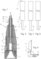
- the optical fiber is shown in an enlarged side view in Fig. 4 .
- the distal end 31 of the optical fiber is exposed by removing a covering 32 of the fiber over a portion adjacent the end thereof, such as over a length of about 12 mm.
- the semicircular recess 27 of the retainer 26 may have a length of 8 mm and the portion of the optical fiber extending out of the retainer 26 may be about 4 mm.
- the distal end of the patient optical fiber is shaped as a cone 33 by machining the end of the fiber, for example by laser or by mechanical operation. The cone angle is approximately 90 degrees.
- the total length of the patient optical fiber may be for example about 100 mm.
- the proximal end 34 of the fiber is cut at a right angle.
- the patient fiber proximal end surface is machined so that it is sufficiently transparent for light as explained in more detail below.
- the outer diameter of the optical fiber may be approximately 2.2 mm and the optical core of the optical fiber may have a diameter of about 0.75 mm.
- the optical fiber is selected to be of standard quality.
- the core is made of a plastics material having an index of refraction, which as about 1.5 (PMMA plastics).
- the optic core is transparent for light at a red wavelength, such as 690 nm. Such a fiber can be obtained from many manufacturers at a very low price, for example Toray Japan.
- Optical fibers of other qualities may be used, such as a fiber with a glass core.
- the properties of the optical fiber may be selected so that a standard fiber may be used, which makes the price low.
- the optical fiber is normally straight, without any bends. However, the optical fiber may be exposed to smaller bends without influencing upon the operation of the device.
- the distal end of the fiber may have another shape than conical, as long as almost complete total internal reflection is obtained at the distal end, when it is surrounded by air.
- a shape may be semi-circular or drip-shaped 35 as shown in Fig. 5 or frusto-conical 36 as shown in Fig. 6 .
- the compress 29 is attached over the exposed distal end of the patient optical fiber so that the distal end is embedded in the compress.
- a fluid such as blood
- the fluid will be sucked up by the compress and distributed inside the compress.
- a predetermined amount of fluid such as about 0.2 to 2 milliliters, have been absorbed by the compress, the fluid reaches the center of the compress and the distal end of the optical fiber enclosed therein.
- the distal end of the optical fiber is exposed to or contacted by the fluid, the total internal reflection ceases.
- the entire patient unit 12 is made in a manner so that it is as inexpensive as possible.
- the patient unit is disposable and is used only once per treatment.
- the patient unit should be sterilized.
- the patient unit 12 is connected to the monitoring unit 16 by a connection unit 14.
- connection unit 14 does not need to be sterilized, since it is relatively far away from the wound or vascular access.
- the connection unit can be used several times and for different patients. However, certain facilities may want to use the same connection unit for the same patient, when the patient returns for successive treatments.
- a hemodialysis patient normally obtains dialysis treatment each second day, or trice per week.
- the connection unit may be used for several hundreds of treatments or more.
- connection unit can be made to be more expensive than the patient unit, which is disposable.
- connection unit 14 essentially comprises an optical fiber 51 provided with a patient connector 52 at the distal end and a monitor connector 53 at the proximal end, see Fig. 1 .
- the length of the connection optical fiber 51 may be for example 2 m, which is sufficient for attachment to a monitor unit 16 arranged at a dialysis machine.
- the connection unit may be much shorter, for example about 200 mm.
- connection unit is integrated in the monitor unit 16 so that the connector 52 is arranged in the monitor unit and extends out from the monitor unit.
- the patient optical fiber may be longer, for example about 250 mm as shown in Fig. 16 .
- connection optical fiber may be winded into a bundle 54 as shown in Fig. 1 . It is important that the optical fiber is not bent too sharply.
- connection unit Since the connection unit should be used several times, it should be able to withstand normally occurring cleaning agents at a hospital, such as alcohol and acids.
- the optical fiber may be arranged inside a tube made of a plastics material, which is normally used in hospital environments, such as PVC or an elastomer material.
- the tube material may be transparent so that damages of the optical fibers are visible if visible light is used.
- the connecting fiber should be protected from being exposed to a small radius, as may occur if the fiber is kinked or bent sharply.
- the connecting fiber may be arranged inside a holder, such as a bobbin having a spindle or cylinder with flanges as described in connection with Fig. 12 below.
- connection optical fiber comprises a standard connector 53 for connection to a light transmitter and receiver, as explained further below.
- connection optical fiber comprises the patient connector 52 adapted for connection to the proximal end of the patient optical fiber 28.
- the patient connector 52 is shown in more detail in Fig. 7 .
- the upper end of the connector 52 as shown in Fig.7 receives the connection optical fiber 51 as described above, in a cylindrical opening 61, which may have a diameter of about 3.25 mm in order to receive the connection optical fiber 62 having a diameter of 0.8 mm and a transparent hose 63 having an external diameter of 3.2 mm and a material thickness of about 1.1 mm.
- the distal end of the connection optical fiber extends through a small hole 65 having a diameter of 0.8 mm, which is equally large as the core of the connection optical fiber 66.
- the distal end 67 of the connection optical fiber 51 protrudes a few tenth of a millimeter out of the hole 65 as shown in Fig. 7 .
- the optical fiber and the transparent hose are all secured inside the openings 61 and 65, for example by an adhesive.
- connection optical fiber is not provided with any covering but the transparent flexible hose 63.
- the optical fiber is bent with a small radius, so that light leaks out of the fiber, such light will be visible through the hose 63. If the light is red, as in one embodiment, such a bend will be visible since the fiber glowes with a red light at such a position.
- the patient connector 52 is generally cylindrical and comprises at the bottom end seen according to Fig. 7 , a conical entrance opening 71 for insertion of the proximal end of the patient optical fiber.
- the entrance is generally conical, so that the patient optical fiber end can easily be inserted into the entrance opening.
- a cylindrical recess 72 is connected to the entrance, so that the patient optical fiber may be inserted into the cylindrical opening via the entrance opening 71.
- the cylindrical recess 72 has a diameter, which is slightly larger than the external diameter of the patient optical fiber, such as 2.3 mm.
- the patient optical fiber can be inserted through the entrance and into the cylindrical opening.
- the proximal end of the patient optical fiber will be arranged in line with and in contact with the distal end of the connection optical fiber, which is protruding from the narrow hole 65. In this way, light may be transmitted between the optical fibers.
- the cylindrical recess 72 has a length, which is adapted for ensuring that any mis-alinement between the optical fibers is as small as possible.
- a suitable length is about 10 mm.
- a spring member 73 adjacent the transition between the entrance opening 71 and the cylindrical recess 72, there is arranged a spring member 73, which is further shown in perspective in Fig. 8 .
- the spring member comprises a radial portion 74, which extends over the cylindrical recess 72 and at least partly occludes this recess 72.
- the radial portion 74 comprises a hole 75 having a diameter, which is slightly larger than the outer diameter of the patient optical fiber.
- the spring member 73 further comprises an operation portion 77 extending along the outer side of the connector as shown in Fig. 7 . At the connection between the radial portion 74 and the operation portion 77, there is a bend over slightly more than 90 degrees so that there is formed a distance 76 between the spring and the connector.
- the radial portion 74 Upon pressure at said bend, the radial portion 74 is moved in the radial direction against the spring action of the spring member. During such a movement, the hole 75 in the radial portion 74 comes into register with the cylindrical recess 72 in the connector, whereby a patient optical fiber may be inserted in the cylindrical recess 72 as described above. When the pressure on the bend of the spring is relieved, the sides of the hole 75 will exert a pressure at the side surface of the patient optical fiber, thereby retaining the optical fiber in the connector.
- the spring 73 and the hole 75 are dimensioned so that there is required a specific force for removing the patient optical fiber.
- This force is dimensioned so that the withdrawal force is smaller than the force required to remove the patch from the skin of the patient by pulling the fiber patient optical fiber.
- the adhesive of the patch may be dimensioned so that a force of about 30 Newton is required for removing the patch.
- the force required for withdrawing the patient optical fiber from the connector is smaller than 30 N, for example about 20 N.
- the force required for withdrawing the fiber from the connector should be sufficiently large for preventing unintended withdrawal of the fiber.
- a safe force would be about 10 N or larger. In other applications, a minimum safe force for withdrawing the fiber would be for example 15 N.
- the force from the spring member 73 acts upon the patient optical fiber in the radial direction.
- the optical fiber is forced against the side surface of the cylindrical recess 72.
- the patient optical fiber is arranged more closely in line with the connection optical fiber.
- Fig. 9 is a cross-sectional view of an alternative patient connector unit 80.
- the connector unit 80 is substantially similar to the connection unit shown in Fig. 7 .
- the connection unit 80 is provided with a second spring member 83 arranged opposite to the first spring member 73.
- the two spring members may be operated at the same time by a single hand of the user.
- the safety is increased.
- Such a spring back position may be indicated by a colored portion at the spring member at position 84.
- the portion of the spring 83 extending inside the connector unit 80 may have a red color. When the spring 83 is relieved, a part of the red color portion 84 becomes visible from the outside.
- an inspection hole 85 extending from the point of contact between the patient optical fiber and the connection optical fiber. If there is improper contact, there will be a leakage of light, which is visible through the hole 85 as a red light, if red light is used in the optical fiber.
- light guides which guides the light out to the periphery of the connector, for example at several positions.
- the monitor device is arranged to test the connection and indicate malfunction if the amount of light returned to the photo detector is smaller than expected. If the operation is normal, for example about 90% of the emitted light is sensed by the detector, whereby light is lost during the transmission through the optical fibers, in the connectors and at the distal end.
- the detector signal decreases to about 25% to 40% of the emitted light during a relatively short time of about less than 1-2 seconds. If the detector is slowly exposed to fluid such as sweat, the signal level at the detector continuously decreases over a relatively long time, such as a decrease of about 10% or less over 10 seconds. If the patient optical fiber is withdrawn, the signal at the detector decreases to about 10% of the emitted light or even lower. Thus, the detector is able to differentiate between such conditions.
- the light returned to the detector is mainly light, which has passed out into the blood and illuminates the blood. A part of the red light returned or scattered by the blood enters the patient optical fiber and is sent back to the detector.
- Fig. 10 shows a further embodiment of the connector shown in Fig. 7 .
- the connection optical fiber 51 is shorter and extends only partially through the hole 65 so that the distal end of the optical fiber ends at 87 as shown in Fig. 10 .
- the end of the small hole 65 facing towards the patient optical fiber is chamfered as shown at 88, so that a conical entrance into the small hole 65 is obtained.
- the patient optical fiber is provided with a proximal end in which the covering 42 is partly peeled off and a portion of the core of the optical fiber is exposed.
- the core of the patient optical fiber extends into the hole 65 into abutment with the distal end of the connection optical fiber. Otherwise, the operation is substantially the same as the embodiment described with reference to Fig. 7 .
- Fig. 11 is a cross-sectional view of a construction according to the invention in which a withdrawal force is exerted by one or several rotational members 78.
- Each rotational member 78 is arranged so that rotation in one direction may take place without any restriction, but rotation in the opposite direction is prevented.
- Four rotational members 78 or rollers are shown in Fig. 11 .
- the rotational members 78 are arranged so that insertion of a patient optical fiber into the cylindrical recess 82 may take place without any hindrance, since the rollers easily rotate in a corresponding direction. However, once entered, the optical fiber cannot easily be withdrawn, because the rollers are prevented from rotation in the direction in which the optical fiber is withdrawn.
- the rollers retain the optical fiber in the cylindrical recess 82 by friction.
- the frictional force exerted by the roller against the side-wall of the optical fiber is controlled by a spring 79, which acts upon the roller 82 as shown in Fig. 11 for one of the rollers.
- the force of the spring is adjusted by a screw 81.
- the other rollers may or may not be provided with similar spring and screw members.
- the rollers may be made of a slightly elastic material, such as rubber.
- Fig 12 is a perspective view of a connection optical fiber 51, provided with a patient connector 52 and a monitor connector 53. Only one revolution is shown in Fig. 12 but there may be several revolutions as shown in Fig. 1 , depending on the length of the optical fiber 51.
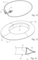
- Fig. 13 is a perspective view of a bobbin 90 for enclosing the optical fiber 51 during transport and storage, between uses thereof.
- Fig. 14 is a cross-sectional view of the bobbin 90. As shown, the bobbin comprises a central portion 91, which is circular or oval. The inner wall of the central portion 91 may be slightly curved as shown in Fig. 14 .
- Two flanges 92 and 93 are attached at each end of the central portion 91.
- the flanges are inclined towards each other and form together with the central portion a triangular space, inside which the connection optical fiber may be arranged.
- the flanges are elastic so that they may be removed from each other and open the triangular space for insertion or removal of the optical fiber.
- the walls of the flanges 92 and 93 may be reinforced by springs made from wire and having the same shape as the cross-section and being arranged at suitable distances along the periphery of the bobbin.
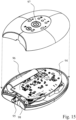
- the central portion is arranged complementary to a monitoring device 16 shown in Fig. 15 .
- the monitoring device is shown in an exploded view to shown the internal units of the monitoring device.
- the outer shape of the monitoring device fits snuggly in the central portion 91. Because of the slightly curved inner surface of the central portion 91 as shown in Fig. 14 , the central portion 91 is retained on the monitoring device.
- the monitoring device comprises electronic circuits 94 arranged for performing the monitoring operation as described above.
- the exact arrangement of the electronic units is not critical, but has to fulfill all requirements of safe operation as required for medical device use in hospital or home care.
- the monitoring device comprises an optical module, comprising a female connector 95, a light source and a photo detector.
- the optical module 98 may for example by an optical unit of the type LD655 made by OECA, Germany, and comprises a 655 nm laserdiode and a Silicon PIN photodiode. Both units are coupled to a ST-Port for POF using a dielectrical beamsplitter.
- the monitoring device further comprises a battery 96, a microprocessor (not shown) and several light emitting diodes LED:s and several switches.
- a piezo-electric buzzer (not shown) provides an audible alarm.
- a piezo-electric horn and driver (not shown) may be arranged for emitting a loud noice in a critical situation, sounding like a fire alarm signal.
- a start button 97 At the middle of the monitoring device, there is arranged a start button 97 and at the bottom side of the monitoring module there are arranged several electrical connectors for connection to the hospital monitoring system or other external alarm system or other medical device. In addition, communication with the hospital monitoring system may take place by wireless devices.
- the monitoring device is arranged to emit a light beam via the laserdiode into the connection optical fiber 51, which is connected to the female connector 95.
- the light is further transmitted from the connection optical fiber 51 to the patient optical fiber 31 via the patient connector 52.
- the light reaches the distal end of the patient optical fiber and is normally exposed to total internal reflection at the surfaces of the distal end.
- the light passes back along the patient optical fiber and to the connection optical fiber and finally reaches the photo detector.
- the distal end of the patient optical fiber is not covered with a fluid, almost all of the emitted light is reflected back to the photodiode. Only a small portion is lost because of transmission losses and in the two connectors. Normally, more than 90 % of the emitted light is reflected back to the photo detector.
- the light when the distal end is at least partly covered by blood, the light is not reflected by the conical surfaces and only a small portion, such as less than 50%, of the emitted light is returned to the photo detector. It is mainly light which is scattered and redirected by the blood back into the optical fiber which is returned. There is also a leakage in the connectors.
- the presence of blood at the patch may be monitored.
- the device is very sensitive, since a large decrease in light received by the photodiode is obtained when the distal end is contacted by blood.
- the returned light is decreased to less than 50 % when blood is sensed.
- the compress may also absorb water, such as sweat. Water has substantially the same influence upon the optical properties of the distal end. Thus, if the compress is soaked with sweat or if water is spilled at the compress, a false alarm may be emitted. However, this problem may be solved by the electronic circuits and software in the monitoring device. Normally, the presence of sweat increases very slowly. Thus, a slow decrease in the returned light is an indication of the fact that sweat may disturb the monitoring operation. In such a situation, the monitoring device may emit an indication that the compress should be replaced.
- a blood alarm signal is only generated if the decrease in returned light is sudden. For example, a decrease of returned light by more than 40% during less than 3 seconds may result in an alarm.
- the bobbin is not required in certain applications, but the optical fiber may be sufficiently short as shown in Fig. 12 in order not to need to be winded, or may be winded outside the monitor unit.
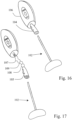
- connection unit and the monitor unit may form a single unit by having the connection optical fiber directly connected to the monitor unit without a monitor connector 53 or without a connection unit 14.
- a monitor connector 53 or without a connection unit 14 Such an embodiment is shown in Fig. 16 .
- the patient connector 104 is integrated in the monitor unit 106, and the patient optical fiber 102 is inserted directly into the patient connector 104 and withheld therein with a predetermined force, which is sufficiently low, such as 15N.
- the monitor unit 106 is attached to the arm of the patient, for example by a strap.
- the patient connector 104 may be connected to the monitor unit 106 with an elastic device so that the patient connector 104 is easily moveable over one or several centimeters in the longitudinal direction of the patient connector, in order to accommodate normal movements of the patient and the device.
- the patient connector 52 may comprise the optical unit 98, see Fig. 15 , which is now integrated in the patient connector.
- the optical unit 108 is shown only schematically as a circular unit. Several electrical wires 107 and 109 connect the optical unit 108 with the monitor unit 106 or 16.
- the patient connector 105 provided with the optical unit 108 is attached to the arm of the patient with a strap or tape.
- the disposable patient unit can be made very inexpensively, since the patient optical fiber does not need any expensive machining or treatment. It is only required to form the distal end into a conical surface and to cut the proximal end at substantially 90 degrees.
- the surface of the exposed fiber core may need some machining so that any irregularities caused by the machining is removed, such as polishing.
- the cutting and polishing can be made in one and the same step by a cutting disk. If the cutting action is performed by a laser, the surfaces normally do not need any post-treatment.
- the length of the patient optical fiber is as small as possible, but so that the proximal end is sufficiently long away from the area to be kept sterile. Such a length may be about 100 mm.
- the patient optical fiber in these constructions is a double optical fiber extending in a loop.
- the proximal end of the double optical fiber may be inserted in a patient connector 52, which is modified so that the cylindrical recess 72 is oval.
- the connector optical fiber may comprise double fibers.
- the modified patient connector may comprise a beam splitter.
- the optical unit 108 may comprise a laser diode, which is arranged in line with one of the double optical fibers and a photo detector, which is arranged in line with the other optical fiber of the double optical fibers. Other modifications may arise to a skilled person.
- the light used in the embodiment described above may comprise red light of a wavelength of about 630 to 690 nm.
- Many different commercial laser diodes are made by many different manufacturers and such laser diodes may be obtained at a low price.
- photo detectors are inexpensive for light in this wavelength area. Infrared light may be used as an alternative.
Description
- The present invention relates to a device for monitoring of blood leakage from wounds. One particular field is monitoring of vascular access of a patient during extracorporeal treatment, such as dialysis.
-
WO2006/001759A1 issued to the assignee of the present invention, discloses a method and means for detection of blood leakage from wounds by means of an optical fiber. The optical fiber is arranged in a loop from a light source to a patch to be attached to the patient and back to a light detector. The light source and light detector are arranged in a monitoring device at a distance from the patch and may be attached to the arm of a patient. The loop comprises a sensor portion arranged at the patch and in which the optical fiber is bent with a small radius, so that the total internal reflection angle inside the optical fiber is approached or exceeded. A portion of the light transmitted through the optical fiber passes out through the sidewall of the optical fiber in the small radius sensor portion. When the sensor portion is exposed to a fluid, such as water or blood, the portion of the light passing out through the sidewall of the optical fiber in the small radius sensor portion increases, which may be sensed by the light detector as a decrease in light intensity, which may trigger an alarm. - The device according to
WO2006/001759A1 operates well and is able to monitor for example a vascular access in an extracorporeal treatment, such as dialysis. - However, the manufacturing costs of said device may be further decreased. In addition, the amount of surplus material during manufacturing may be reduced. Furthermore, the security of the connection of the patient device to the monitor may be improved. However, a reduction of costs and operation requires a new technology to be used.
- It is noted that the patient portion should be sterile and is disposable. However, the monitoring unit including the light source and detector and further electronic circuits is reusable. Thus, a reduction of costs per treatment may be obtained by reducing the costs of the disposable patient portion.
- Another problem is relocation of the patch when the optical fiber is exposed to a force. When the patient is moving, the optical fiber may be influenced upon resulting in the fact that the patch is removed. This may remain unnoticed for a long time. When it is noticed, it is sometimes difficult to relocate the patch and it may be required to attach a new patch. If the relocation remains unnoticed, this is a safety risk.
-
WO2008/036149A2 discloses a devices for visually confirming the positioning of a distal end portion of an illuminating device placed within a patient, and includes inserting a distal end portion of an illuminating device internally into a patient, emitting light from the distal end portion of the illuminating device, observing transillumination resulting from the light emitted from the distal end portion of the illuminating device that occurs on an external surface of the patient, and correlating the location of the observed transillumination on the external surface of the patient with an internal location of the patient that underlies the location of observed transillumination, to confirm positioning of the distal end portion of the illuminating device. - Accordingly, an object of the present invention is to mitigate, alleviate or eliminate one or more of the above-identified deficiencies and disadvantages singly or in any combination.
- Further objects, features and advantages of the invention will become apparent from the following detailed description of embodiments of the invention with reference to the drawings, in which:
-
Fig. 1 is a schematic view of an embodiment of the monitoring device according to the invention. -
Fig. 2 is an exploded view of the patient unit. -
Fig. 3 is a plan view of the patient unit. -
Figs. 4, 5 and 6 are side views of a distal end of the patient optical fiber. -
Fig. 7 is a cross-sectional view of the connector. -
Fig. 8 is a perspective view of the spring member. -
Fig. 9 is a cross-sectional view of another embodiment of the connector. -
Fig. 10 is a cross-sectional view of a further embodiment of the connector. -
Fig. 11 is a cross-sectional view of a still further embodiment of the connector. -
Fig. 12 is a perspective view of the connection optical fiber. -
Fig. 13 is a perspective view of a bobbin. -
Fig. 14 is a cross-sectional view of a portion of the bobbin. -
Fig. 15 is an exploded view of the monitor unit. -
Fig. 16 is a perspective view similar toFig. 1 of another embodiment. -
Fig. 17 is a perspective view similar toFig. 1 of still another embodiment. - Below, several embodiments of the invention will be described. These embodiments are described in illustrating purpose in order to enable a skilled person to carry out the invention and to disclose the best mode. However, such embodiments do not limit the scope of the invention. Moreover, certain combinations of features are shown and discussed. However, other combinations of the different features are possible within the scope of the invention.
- The general operation of a device according to the invention is the following. A patch is attached to the patient adjacent the site to be monitored, such as a vascular access of a dialysis patient. The patch comprises a compress for absorbing blood emitted from the vascular access, which is an indication of an alarm condition.
- Embedded inside the patch is a distal end of an optical fiber, which may be shaped as a cone and is exposed to the surrounding atmosphere, which is air, inside the compress. The proximal end of the optical fiber is connected to a light transmitter and a photo detector. Light transmitted through the optical fiber towards the distal end is normally reflected back 180 degrees to the photo detector by total internal reflection at the distal end surface of the fiber. If blood reaches and is contacting the exposed conical surface of the optical fiber, the total internal reflection disappears at the contacting area and light passes out through the distal end of the fiber. Then, the signal level at the photo detector decreases, which may cause an alarm or an alert situation. The expression proximal and distal are as seen from the monitor side, which means that the distal end is closest to the needle, catheter or wound to be monitored for bleeding.
- Bleeding may occur if a venous needle of a vascular access is removed during treatment. Normally, during an extracorporeal treatment, such as dialysis, blood is returned to the body via a venous needle. In such a treatment, the blood flow may be about 200 to 500 ml/min. If the venous needle accidentally is removed from the vein, the returning blood flow passes out of the needle instead of being returned to the patient. If such a situation remains unnoticed for only 2 minutes, a life threatening condition develops. However, when the venous needle is dislocated, blood is emitted and may be detected adjacent the blood access location. Often, the venous needle is rapidly removed far away from the access site, for example down the floor. However, the venous needle will emit a sufficient amount of blood to be detected at the access site even at a rapid removal. However, sometimes the blood left at the access site is very small, only a droplet, and the bulk of the blood is discharged for example at the floor. In addition, blood may leak from the vein and out through the hole in the skin left by the venous needle, at least for a short time duration. During the extracorporeal treatment, blood is also removed from a patient via an arterial needle. If such an arterial needle is removed or dislocated, this is not particularly dangerous, since such a dislocation only results in that blood is not removed out to the extracorporeal circuit, which only results in that the desired treatment is not achieved. However, the arterial needle access can also be monitored by the present embodiments of the invention. Also, other sites on the skin of a patient may be monitored for blood, such as a wound.
-
Fig. 1 is a schematic overview of the components of adevice 10 according to a first embodiment of the invention. Thedevice 10 according to the first embodiment comprises apatient unit 12, aconnection unit 14 and amonitor unit 16. Thepatient unit 12 is intended for attachment to a patient adjacent a wound or a vascular access to be monitored. Themonitor unit 16 comprises electronic devices for monitoring thepatient unit 12. Theconnection unit 14 is for connection of thepatient unit 12 to themonitor unit 16. - The
patient unit 12 is shown in more detail inFig. 2 . The patient unit comprises apatch 21 of a flexible web material. The patch is covered by aplastics material 22 at the bottom side as seen inFig. 2 , over at least a portion thereof, as shown bybroken lines 23. The bottom side is facing away from the skin the patch is applied to the skin in a monitoring position. In addition, the upper side of the patch is partly covered by anadhesive layer 24 protected by aremovable layer 25. By removing theremovable layer 25, theadhesive layer 24 becomes exposed and may attach the patch to the skin of a patient, for example adjacent a vascular access. The adhesive is dimensioned so that a specific removal force is required for removing the patch from the skin surface. Such a removal force may be about 30 Newton. - A central portion of the pad is provided with a
retainer 26 of a rigid material. Theretainer 26 comprises asemicircular recess 27 in which a distal end of anoptical fiber 28 is arranged. The distal end of theoptical fiber 28 is arranged in acompress 29 of a soft material, which is able to absorb a fluid such as blood. - The patch is attached to the skin of a patient with the
compress 29 arranged at the skin surface adjacent or over the vascular access. The vascular access may extend in the opposite direction in relation to theoptical fiber 28, so that the vascular access may be moved and even removed without influencing upon the patch and its attachment to the skin surface. - The exposed distal end of the optical fiber having it's covering peeled off is enclosed in the
recess 27 of theretainer 26. The distal end of the optical fiber extends out of therecess 27 for a short distance. Theretainer 26 further compriseswings patch 21. - The
patch 21 is shown in a plan view inFig. 3 . The patch comprises twolugs retainer 26 is arranged in the position 26' shown inFig. 3 by broken lines with the optical fiber in therecess 27, thelugs retainer wings broken line arrows Fig. 3 and glued in place by an adhesive. The optical fiber may also be kept in place in the retainer recess by means of an adhesive. By means of theretainer 26, the distal end of the optical fiber will be firmly held in place in the middle of the patch as shown by broken lines 28' inFig. 3 . - The optical fiber is shown in an enlarged side view in
Fig. 4 . Thedistal end 31 of the optical fiber is exposed by removing a covering 32 of the fiber over a portion adjacent the end thereof, such as over a length of about 12 mm. Thesemicircular recess 27 of theretainer 26 may have a length of 8 mm and the portion of the optical fiber extending out of theretainer 26 may be about 4 mm. The distal end of the patient optical fiber is shaped as acone 33 by machining the end of the fiber, for example by laser or by mechanical operation. The cone angle is approximately 90 degrees. The total length of the patient optical fiber may be for example about 100 mm. - The
proximal end 34 of the fiber is cut at a right angle. The patient fiber proximal end surface is machined so that it is sufficiently transparent for light as explained in more detail below. The outer diameter of the optical fiber may be approximately 2.2 mm and the optical core of the optical fiber may have a diameter of about 0.75 mm. - The optical fiber is selected to be of standard quality. The core is made of a plastics material having an index of refraction, which as about 1.5 (PMMA plastics). The optic core is transparent for light at a red wavelength, such as 690 nm. Such a fiber can be obtained from many manufacturers at a very low price, for example Toray Japan.
- Optical fibers of other qualities may be used, such as a fiber with a glass core. However, the properties of the optical fiber may be selected so that a standard fiber may be used, which makes the price low.
- The optical fiber is normally straight, without any bends. However, the optical fiber may be exposed to smaller bends without influencing upon the operation of the device.
- In alternative embodiments, the distal end of the fiber may have another shape than conical, as long as almost complete total internal reflection is obtained at the distal end, when it is surrounded by air. Such a shape may be semi-circular or drip-shaped 35 as shown in
Fig. 5 or frusto-conical 36 as shown inFig. 6 . - The
compress 29 is attached over the exposed distal end of the patient optical fiber so that the distal end is embedded in the compress. When the compress comes into contact with a fluid, such as blood, the fluid will be sucked up by the compress and distributed inside the compress. When a predetermined amount of fluid, such as about 0.2 to 2 milliliters, have been absorbed by the compress, the fluid reaches the center of the compress and the distal end of the optical fiber enclosed therein. When the distal end of the optical fiber is exposed to or contacted by the fluid, the total internal reflection ceases. - The
entire patient unit 12 is made in a manner so that it is as inexpensive as possible. The patient unit is disposable and is used only once per treatment. The patient unit should be sterilized. - The
patient unit 12 is connected to themonitoring unit 16 by aconnection unit 14. - The
connection unit 14 does not need to be sterilized, since it is relatively far away from the wound or vascular access. The connection unit can be used several times and for different patients. However, certain facilities may want to use the same connection unit for the same patient, when the patient returns for successive treatments. A hemodialysis patient normally obtains dialysis treatment each second day, or trice per week. The connection unit may be used for several hundreds of treatments or more. - Consequently, the connection unit can be made to be more expensive than the patient unit, which is disposable.
- The
connection unit 14 essentially comprises anoptical fiber 51 provided with apatient connector 52 at the distal end and amonitor connector 53 at the proximal end, seeFig. 1 . The length of the connectionoptical fiber 51 may be for example 2 m, which is sufficient for attachment to amonitor unit 16 arranged at a dialysis machine. However, if the monitor unit is attached to the patient, for example at the arm of the patient, the connection unit may be much shorter, for example about 200 mm. - In another embodiment, the connection unit is integrated in the
monitor unit 16 so that theconnector 52 is arranged in the monitor unit and extends out from the monitor unit. In this embodiment, the patient optical fiber may be longer, for example about 250 mm as shown inFig. 16 . - The connection optical fiber may be winded into a
bundle 54 as shown inFig. 1 . It is important that the optical fiber is not bent too sharply. - Since the connection unit should be used several times, it should be able to withstand normally occurring cleaning agents at a hospital, such as alcohol and acids. The optical fiber may be arranged inside a tube made of a plastics material, which is normally used in hospital environments, such as PVC or an elastomer material. The tube material may be transparent so that damages of the optical fibers are visible if visible light is used.
- The optical fiber should be protected from being exposed to a small radius, as may occur if the fiber is kinked or bent sharply. Thus, the connecting fiber may be arranged inside a holder, such as a bobbin having a spindle or cylinder with flanges as described in connection with
Fig. 12 below. - The proximal end of the connection optical fiber comprises a
standard connector 53 for connection to a light transmitter and receiver, as explained further below. - The distal end of the connection optical fiber comprises the
patient connector 52 adapted for connection to the proximal end of the patientoptical fiber 28. - The
patient connector 52 is shown in more detail inFig. 7 . The upper end of theconnector 52 as shown inFig.7 receives the connectionoptical fiber 51 as described above, in acylindrical opening 61, which may have a diameter of about 3.25 mm in order to receive the connectionoptical fiber 62 having a diameter of 0.8 mm and atransparent hose 63 having an external diameter of 3.2 mm and a material thickness of about 1.1 mm. The distal end of the connection optical fiber extends through asmall hole 65 having a diameter of 0.8 mm, which is equally large as the core of the connectionoptical fiber 66. Thedistal end 67 of the connectionoptical fiber 51 protrudes a few tenth of a millimeter out of thehole 65 as shown inFig. 7 . The optical fiber and the transparent hose are all secured inside theopenings - The
core 66 of the connection optical fiber is not provided with any covering but the transparentflexible hose 63. Thus, if the optical fiber is bent with a small radius, so that light leaks out of the fiber, such light will be visible through thehose 63. If the light is red, as in one embodiment, such a bend will be visible since the fiber glowes with a red light at such a position. - The
patient connector 52 is generally cylindrical and comprises at the bottom end seen according toFig. 7 , a conical entrance opening 71 for insertion of the proximal end of the patient optical fiber. The entrance is generally conical, so that the patient optical fiber end can easily be inserted into the entrance opening. - A cylindrical recess 72 is connected to the entrance, so that the patient optical fiber may be inserted into the cylindrical opening via the
entrance opening 71. The cylindrical recess 72 has a diameter, which is slightly larger than the external diameter of the patient optical fiber, such as 2.3 mm. Thus, the patient optical fiber can be inserted through the entrance and into the cylindrical opening. Then, the proximal end of the patient optical fiber will be arranged in line with and in contact with the distal end of the connection optical fiber, which is protruding from thenarrow hole 65. In this way, light may be transmitted between the optical fibers. - It is important that the patient optical fiber is arranged in line with the connection optical fiber otherwise the transmission of light may be impaired. Thus, the cylindrical recess 72 has a length, which is adapted for ensuring that any mis-alinement between the optical fibers is as small as possible. A suitable length is about 10 mm.
- According to the invention, adjacent the transition between the
entrance opening 71 and the cylindrical recess 72, there is arranged aspring member 73, which is further shown in perspective inFig. 8 . The spring member comprises aradial portion 74, which extends over the cylindrical recess 72 and at least partly occludes this recess 72. Theradial portion 74 comprises ahole 75 having a diameter, which is slightly larger than the outer diameter of the patient optical fiber. Thespring member 73 further comprises anoperation portion 77 extending along the outer side of the connector as shown inFig. 7 . At the connection between theradial portion 74 and theoperation portion 77, there is a bend over slightly more than 90 degrees so that there is formed adistance 76 between the spring and the connector. Upon pressure at said bend, theradial portion 74 is moved in the radial direction against the spring action of the spring member. During such a movement, thehole 75 in theradial portion 74 comes into register with the cylindrical recess 72 in the connector, whereby a patient optical fiber may be inserted in the cylindrical recess 72 as described above. When the pressure on the bend of the spring is relieved, the sides of thehole 75 will exert a pressure at the side surface of the patient optical fiber, thereby retaining the optical fiber in the connector. - According to the invention, the
spring 73 and thehole 75 are dimensioned so that there is required a specific force for removing the patient optical fiber. This force is dimensioned so that the withdrawal force is smaller than the force required to remove the patch from the skin of the patient by pulling the fiber patient optical fiber. The adhesive of the patch may be dimensioned so that a force of about 30 Newton is required for removing the patch. In this case, the force required for withdrawing the patient optical fiber from the connector is smaller than 30 N, for example about 20 N. On the other hand, the force required for withdrawing the fiber from the connector should be sufficiently large for preventing unintended withdrawal of the fiber. Such a safe force would be about 10 N or larger. In other applications, a minimum safe force for withdrawing the fiber would be for example 15 N. - By this measure, it is ensured that the connector releases the patient optical fiber before the patch is removed from the patient, in case a large force acts upon the connection optical fiber. If this happens, it is easier to re-attach the optical fiber to the connector than to replace the patch on the skin of the patient.
- If the patient optical fiber is withdrawn from the connector, this action results in the fact that the reflected light from the patient distal fiber end ceases. Thus, an alarm is initiated and the optical fiber may be re-attached or relocated into the connector. However, if the patch is removed from its position, without withdrawal of the optical fiber from the
connector 52, this fact is not easily detected. Thus, it is an important safety feature that the optical fiber is withdrawn from the connector before the patch is dislocated. - The force from the
spring member 73 acts upon the patient optical fiber in the radial direction. By this action, the optical fiber is forced against the side surface of the cylindrical recess 72. By this action, the patient optical fiber is arranged more closely in line with the connection optical fiber. -
Fig. 9 is a cross-sectional view of an alternativepatient connector unit 80. Theconnector unit 80 is substantially similar to the connection unit shown inFig. 7 . However, theconnection unit 80 is provided with asecond spring member 83 arranged opposite to thefirst spring member 73. Thus, the two spring members may be operated at the same time by a single hand of the user. By arranging two spring members, the safety is increased. In addition, it is ensured that the patient optical fiber is properly inserted into the cylindrical opening, because, if the patient optical fiber is not pushed entirely into the opening, thesecond spring member 83 will spring back to its original position. Such a spring back position may be indicated by a colored portion at the spring member atposition 84. Thus, the portion of thespring 83 extending inside theconnector unit 80 may have a red color. When thespring 83 is relieved, a part of thered color portion 84 becomes visible from the outside. - In addition, there may be arranged an
inspection hole 85 extending from the point of contact between the patient optical fiber and the connection optical fiber. If there is improper contact, there will be a leakage of light, which is visible through thehole 85 as a red light, if red light is used in the optical fiber. Instead or in addition to thehole 85, there may be arranged light guides which guides the light out to the periphery of the connector, for example at several positions. - In addition, the monitor device is arranged to test the connection and indicate malfunction if the amount of light returned to the photo detector is smaller than expected. If the operation is normal, for example about 90% of the emitted light is sensed by the detector, whereby light is lost during the transmission through the optical fibers, in the connectors and at the distal end. When the distal end is contacted by or exposed to blood or a fluid, the detector signal decreases to about 25% to 40% of the emitted light during a relatively short time of about less than 1-2 seconds. If the detector is slowly exposed to fluid such as sweat, the signal level at the detector continuously decreases over a relatively long time, such as a decrease of about 10% or less over 10 seconds. If the patient optical fiber is withdrawn, the signal at the detector decreases to about 10% of the emitted light or even lower. Thus, the detector is able to differentiate between such conditions.
- When the distal end of the patient optical fiber is exposed to blood, the light returned to the detector is mainly light, which has passed out into the blood and illuminates the blood. A part of the red light returned or scattered by the blood enters the patient optical fiber and is sent back to the detector.
- If the patient optical fiber is withdrawn from the connector, there is substantially no light returned to the detector.
-
Fig. 10 shows a further embodiment of the connector shown inFig. 7 . The connectionoptical fiber 51 is shorter and extends only partially through thehole 65 so that the distal end of the optical fiber ends at 87 as shown inFig. 10 . The end of thesmall hole 65 facing towards the patient optical fiber is chamfered as shown at 88, so that a conical entrance into thesmall hole 65 is obtained. The patient optical fiber is provided with a proximal end in which the covering 42 is partly peeled off and a portion of the core of the optical fiber is exposed. The core of the patient optical fiber extends into thehole 65 into abutment with the distal end of the connection optical fiber. Otherwise, the operation is substantially the same as the embodiment described with reference toFig. 7 . -
Fig. 11 is a cross-sectional view of a construction according to the invention in which a withdrawal force is exerted by one or severalrotational members 78. Eachrotational member 78 is arranged so that rotation in one direction may take place without any restriction, but rotation in the opposite direction is prevented. Fourrotational members 78 or rollers are shown inFig. 11 . Therotational members 78 are arranged so that insertion of a patient optical fiber into thecylindrical recess 82 may take place without any hindrance, since the rollers easily rotate in a corresponding direction. However, once entered, the optical fiber cannot easily be withdrawn, because the rollers are prevented from rotation in the direction in which the optical fiber is withdrawn. The rollers retain the optical fiber in thecylindrical recess 82 by friction. The frictional force exerted by the roller against the side-wall of the optical fiber is controlled by aspring 79, which acts upon theroller 82 as shown inFig. 11 for one of the rollers. The force of the spring is adjusted by ascrew 81. The other rollers may or may not be provided with similar spring and screw members. The rollers may be made of a slightly elastic material, such as rubber. -
Fig 12 is a perspective view of a connectionoptical fiber 51, provided with apatient connector 52 and amonitor connector 53. Only one revolution is shown inFig. 12 but there may be several revolutions as shown inFig. 1 , depending on the length of theoptical fiber 51. -
Fig. 13 is a perspective view of abobbin 90 for enclosing theoptical fiber 51 during transport and storage, between uses thereof.Fig. 14 is a cross-sectional view of thebobbin 90. As shown, the bobbin comprises acentral portion 91, which is circular or oval. The inner wall of thecentral portion 91 may be slightly curved as shown inFig. 14 . - Two
flanges central portion 91. The flanges are inclined towards each other and form together with the central portion a triangular space, inside which the connection optical fiber may be arranged. The flanges are elastic so that they may be removed from each other and open the triangular space for insertion or removal of the optical fiber. The walls of theflanges - The central portion is arranged complementary to a
monitoring device 16 shown inFig. 15 . The monitoring device is shown in an exploded view to shown the internal units of the monitoring device. - The outer shape of the monitoring device fits snuggly in the
central portion 91. Because of the slightly curved inner surface of thecentral portion 91 as shown inFig. 14 , thecentral portion 91 is retained on the monitoring device. - The monitoring device comprises
electronic circuits 94 arranged for performing the monitoring operation as described above. The exact arrangement of the electronic units is not critical, but has to fulfill all requirements of safe operation as required for medical device use in hospital or home care. The monitoring device comprises an optical module, comprising afemale connector 95, a light source and a photo detector. Theoptical module 98 may for example by an optical unit of the type LD655 made by OECA, Germany, and comprises a 655 nm laserdiode and a Silicon PIN photodiode. Both units are coupled to a ST-Port for POF using a dielectrical beamsplitter. - The monitoring device further comprises a
battery 96, a microprocessor (not shown) and several light emitting diodes LED:s and several switches. A piezo-electric buzzer (not shown) provides an audible alarm. In addition, a piezo-electric horn and driver (not shown) may be arranged for emitting a loud noice in a critical situation, sounding like a fire alarm signal. - At the middle of the monitoring device, there is arranged a
start button 97 and at the bottom side of the monitoring module there are arranged several electrical connectors for connection to the hospital monitoring system or other external alarm system or other medical device. In addition, communication with the hospital monitoring system may take place by wireless devices. - The monitoring device is arranged to emit a light beam via the laserdiode into the connection
optical fiber 51, which is connected to thefemale connector 95. The light is further transmitted from the connectionoptical fiber 51 to the patientoptical fiber 31 via thepatient connector 52. The light reaches the distal end of the patient optical fiber and is normally exposed to total internal reflection at the surfaces of the distal end. The light passes back along the patient optical fiber and to the connection optical fiber and finally reaches the photo detector. - If the distal end of the patient optical fiber is not covered with a fluid, almost all of the emitted light is reflected back to the photodiode. Only a small portion is lost because of transmission losses and in the two connectors. Normally, more than 90 % of the emitted light is reflected back to the photo detector.
- On the other hand, when the distal end is at least partly covered by blood, the light is not reflected by the conical surfaces and only a small portion, such as less than 50%, of the emitted light is returned to the photo detector. It is mainly light which is scattered and redirected by the blood back into the optical fiber which is returned. There is also a leakage in the connectors.
- By monitoring the amount of light received by the photodiode, the presence of blood at the patch may be monitored. The device is very sensitive, since a large decrease in light received by the photodiode is obtained when the distal end is contacted by blood.
- For example, the returned light is decreased to less than 50 % when blood is sensed.
- The compress may also absorb water, such as sweat. Water has substantially the same influence upon the optical properties of the distal end. Thus, if the compress is soaked with sweat or if water is spilled at the compress, a false alarm may be emitted. However, this problem may be solved by the electronic circuits and software in the monitoring device. Normally, the presence of sweat increases very slowly. Thus, a slow decrease in the returned light is an indication of the fact that sweat may disturb the monitoring operation. In such a situation, the monitoring device may emit an indication that the compress should be replaced.
- If the signal decreases slowly, it is an indication of a situation that should not cause a blood alarm. Thus, a blood alarm signal is only generated if the decrease in returned light is sudden. For example, a decrease of returned light by more than 40% during less than 3 seconds may result in an alarm.
- The bobbin is not required in certain applications, but the optical fiber may be sufficiently short as shown in
Fig. 12 in order not to need to be winded, or may be winded outside the monitor unit. - In another embodiments, the connection unit and the monitor unit may form a single unit by having the connection optical fiber directly connected to the monitor unit without a
monitor connector 53 or without aconnection unit 14. Such an embodiment is shown inFig. 16 . Thepatient connector 104 is integrated in themonitor unit 106, and the patientoptical fiber 102 is inserted directly into thepatient connector 104 and withheld therein with a predetermined force, which is sufficiently low, such as 15N. Themonitor unit 106 is attached to the arm of the patient, for example by a strap. Thepatient connector 104 may be connected to themonitor unit 106 with an elastic device so that thepatient connector 104 is easily moveable over one or several centimeters in the longitudinal direction of the patient connector, in order to accommodate normal movements of the patient and the device. - In still another embodiment shown in
Fig. 17 , thepatient connector 52 may comprise theoptical unit 98, seeFig. 15 , which is now integrated in the patient connector. Theoptical unit 108 is shown only schematically as a circular unit. Severalelectrical wires optical unit 108 with themonitor unit patient connector 105 provided with theoptical unit 108 is attached to the arm of the patient with a strap or tape. - The disposable patient unit can be made very inexpensively, since the patient optical fiber does not need any expensive machining or treatment. It is only required to form the distal end into a conical surface and to cut the proximal end at substantially 90 degrees. The surface of the exposed fiber core may need some machining so that any irregularities caused by the machining is removed, such as polishing. Often, the cutting and polishing can be made in one and the same step by a cutting disk. If the cutting action is performed by a laser, the surfaces normally do not need any post-treatment.
- The length of the patient optical fiber is as small as possible, but so that the proximal end is sufficiently long away from the area to be kept sterile. Such a length may be about 100 mm.
- Another type of
patient unit 12 may be used, for example of the type shown in the patent documentsWO 2006/001759 andWO 2008/123814 . The patient optical fiber in these constructions is a double optical fiber extending in a loop. The proximal end of the double optical fiber may be inserted in apatient connector 52, which is modified so that the cylindrical recess 72 is oval. The connector optical fiber may comprise double fibers. Alternatively, the modified patient connector may comprise a beam splitter. In the embodiment ofFig. 17 , theoptical unit 108 may comprise a laser diode, which is arranged in line with one of the double optical fibers and a photo detector, which is arranged in line with the other optical fiber of the double optical fibers. Other modifications may arise to a skilled person. - The light used in the embodiment described above may comprise red light of a wavelength of about 630 to 690 nm. Many different commercial laser diodes are made by many different manufacturers and such laser diodes may be obtained at a low price. Also photo detectors are inexpensive for light in this wavelength area. Infrared light may be used as an alternative.
- In the claims, the term "comprises/comprising" does not exclude the presence of other elements or steps. Furthermore, although individually listed, a plurality of means, elements or method steps may be implemented by e.g. a single unit. Additionally, although individual features may be included in different claims or embodiments, these may possibly advantageously be combined, and the inclusion in different claims does not imply that a combination of features is not feasible and/or advantageous. In addition, singular references do not exclude a plurality. The terms "a", "an", "first", "second" etc do not preclude a plurality. Reference signs in the claims are provided merely as a clarifying example and shall not be construed as limiting the scope of the claims in any way.
- Although the present invention has been described above with reference to specific embodiment and experiments, it is not intended to be limited to the specific form set forth herein. Rather, the invention is limited only by the accompanying claims and, other embodiments than those specified above are equally possible within the scope of the disclosure. The scope of protection is defined by the appended claims.
Claims (7)
- A device for monitoring a skin surface for leakage of blood at a monitoring position comprising a patient unit (12), a connection unit (14) and a monitor unit (16),
whereinthe patient unit comprises a patch (21), including an adhesive layer (24) to be attached to the skin surface adjacent the monitoring position, whereby the adhesive layer is arranged to attach the patch to the skin so that a predetermined removal force is required for removing the patch from the skin surface;the patient unit (12) further comprising a patient optical fiber (28) having an exposed distal end (33) arranged at the patch and a proximal end (34) for connection to the connection unit;the connection unit (14) comprises a connection optical fiber (51), a distal end (67) of which comprises a connector device (52) having an opening (65) passing through the connector device from one end to the other, whereby the connection optical fiber (51) is arranged in a proximal end (61) of the opening and the patient optical fiber (28) is insertable in a distal end (72) of the opening for being arranged with a proximal end of the patient optical fiber in contact with and in register with the distal end (67) of the connection optical fiber,wherein, the connector device (52) comprises a radial spring member (73) arranged so that it normally covers an entrance to said distal end (72) of said opening, whereby the radial spring member further comprises a hole (75), which is moveable into register with said distal end (72) of said opening against a spring action by said radial spring member, thereby permitting entrance of the patient optical fiber (28) into said distal end (72) of said opening, and wherein side surfaces of the hole (75) exerts a force on the patient optical fiber when the radial spring member is released for preventing withdrawal of the patient optical fiber (28), until a predetermined withdrawal force is exerted on the patient optical fiber, whereby the predetermined withdrawal force is smaller than said removal force and is smaller than 30 N but larger than 10 N. - A device for monitoring a skin surface for leakage of blood at a monitoring position comprising a patient unit (12), a connection unit (14) and a monitor unit (16), whereinthe patient unit comprises a patch (21), including an adhesive layer (24) to be attached to the skin surface adjacent the monitoring position, whereby the adhesive layer is arranged to attach the patch to the skin so that a predetermined removal force is required for removing the patch from the skin surface;the patient unit (12) further comprising a patient optical fiber (28) having an exposed distal end (33) arranged at the patch and a proximal end (34) for connection to the connection unit;the connection unit (14) comprises a connection optical fiber (51), a distal end (67) of which comprises a connector device (52) having an opening (65) passing through the connector device from one end to the other, whereby the connection optical fiber (51) is arranged in a proximal end (61) of the opening and the patient optical fiber (28) is insertable in a distal end (72) of the opening for being arranged with a proximal end of the patient optical fiber in contact with and in register with the distal end (67) of the connection optical fiber,wherein,the connector device (52) comprises a force device for exerting a force at the patient optical fiber at a side surface thereof for preventing withdrawal of the patient optical fiber, until a predetermined withdrawal force is exerted on the patient optical fiber,wherein said force device comprises one or several rotational members (78), provided with an elastic material and arranged so that rotation of the rotational members in one direction may take place without restriction, whereby insertion of a patient optical fiber into said opening (65), which is a cylindrical recess (82), takes place without any hindrance, but rotation of the rotational members in the opposite direction is prevented, whereby the optical fiber cannot easily be withdrawn, because the rotational members are prevented from rotation in the direction in which the optical fiber is withdrawn; and a spring (79) exerting a radial force upon the rotational member (78) for providing said withdrawal force, whereby the predetermined withdrawal force is smaller than said predetermined removal force and is smaller than 30 N but larger than 10 N.
- The device according to claim 1 or 2, wherein the proximal end of said patient optical fiber is formed in that the optical fiber including its cover is cut at a substantially right angle and wherein the proximal end of the optical fiber is polished.
- The device according to any one of the previous claims, wherein a distal end of the patient optical fiber is arranged for reflecting back light passing along the optical fiber by total inner reflection when the distal end of the patient optical fiber is surrounded by air.
- The device according to claim 4, wherein the distal end of the patient optical fiber is conical or frusto-conical or semi-spherical.
- The device according to any one of the previous claims, further comprising a side hole (85) arranged between the side surface of the connector and the connection point between the patient optical fiber and the connection optical fiber, for visual inspection of the connection point.
- The device according to any one of the previous claims, wherein the connection unit (14) is integrated in the monitoring unit (16).
Applications Claiming Priority (2)
| Application Number | Priority Date | Filing Date | Title |
|---|---|---|---|
| SE1230031A SE536512C2 (en) | 2012-03-30 | 2012-03-30 | Device for monitoring blood leakage from wounds |
| PCT/SE2013/000041 WO2013147670A1 (en) | 2012-03-30 | 2013-03-22 | Device for monitoring blood leakage from wounds |
Publications (4)
| Publication Number | Publication Date |
|---|---|
| EP2830677A1 EP2830677A1 (en) | 2015-02-04 |
| EP2830677A4 EP2830677A4 (en) | 2015-09-23 |
| EP2830677B1 true EP2830677B1 (en) | 2023-06-07 |
| EP2830677C0 EP2830677C0 (en) | 2023-06-07 |
Family
ID=49260771
Family Applications (1)
| Application Number | Title | Priority Date | Filing Date |
|---|---|---|---|
| EP13767355.4A Active EP2830677B1 (en) | 2012-03-30 | 2013-03-22 | Device for monitoring blood leakage from wounds |
Country Status (9)
| Country | Link |
|---|---|
| US (1) | US9854980B2 (en) |
| EP (1) | EP2830677B1 (en) |
| JP (1) | JP6220855B2 (en) |
| CN (1) | CN104470555B (en) |
| AU (1) | AU2013240629B2 (en) |
| CA (1) | CA2908519C (en) |
| ES (1) | ES2948494T3 (en) |
| SE (1) | SE536512C2 (en) |
| WO (1) | WO2013147670A1 (en) |
Families Citing this family (4)
| Publication number | Priority date | Publication date | Assignee | Title |
|---|---|---|---|---|
| US10933185B2 (en) | 2016-09-16 | 2021-03-02 | Redsense Medical Ab | Device for monitoring hose connectors and body fluid leakage |
| SE542345C2 (en) | 2018-08-03 | 2020-04-14 | Redsense Medical Ab | Device for measuring a property of a measurement object by luminescence |
| SE543645C2 (en) * | 2019-09-02 | 2021-05-11 | Odinwell Ab | Optical device and method for monitoring a measurement object |
| CN115178436A (en) * | 2022-07-05 | 2022-10-14 | 广州大学 | Adhesive dispensing and curing device for multi-section capillary tube packaged fiber grating string |
Citations (3)
| Publication number | Priority date | Publication date | Assignee | Title |
|---|---|---|---|---|
| US4185886A (en) * | 1978-10-26 | 1980-01-29 | International Telephone And Telegraph Corporation | Fiber optic connector |
| WO2004038472A1 (en) * | 2002-10-24 | 2004-05-06 | Ms Engineering Inc. | Connector for optical fiber |
| WO2008036149A2 (en) * | 2006-09-15 | 2008-03-27 | Acclarent, Inc. | Methods and devices for facilitating visualization in a surgical environment |
Family Cites Families (13)
| Publication number | Priority date | Publication date | Assignee | Title |
|---|---|---|---|---|
| US20030128125A1 (en) * | 2002-01-04 | 2003-07-10 | Burbank Jeffrey H. | Method and apparatus for machine error detection by combining multiple sensor inputs |
| US6979306B2 (en) * | 2003-08-13 | 2005-12-27 | Moll Family Trust | Method and device for monitoring loss of body fluid and dislodgment of medical instrument from body |
| SE0401632D0 (en) * | 2004-06-24 | 2004-06-24 | Innovation Team Ab | Means and ways to detect blood leakage from wounds |
| US20060130591A1 (en) | 2004-12-21 | 2006-06-22 | Perkins, Corban Enterprises | Venous needle dislodgement sensor |
| US20070004996A1 (en) * | 2005-06-20 | 2007-01-04 | Lovejoy David A | Needle disengagement sensing mechanism |
| US7641612B1 (en) * | 2006-01-17 | 2010-01-05 | Mccall Kenneth Shawn | Blood loss detection for hemodialysis system |
| US8152751B2 (en) * | 2007-02-09 | 2012-04-10 | Baxter International Inc. | Acoustic access disconnection systems and methods |
| US8376978B2 (en) | 2007-02-09 | 2013-02-19 | Baxter International Inc. | Optical access disconnection systems and methods |
| SE531750C2 (en) | 2007-04-04 | 2009-07-28 | Redsense Medical Malta Ltd | Device for detecting blood leakage |
| US8187184B2 (en) * | 2007-09-21 | 2012-05-29 | Baxter International, Inc. | Access disconnect system with optical and other sensors |
| US8360977B2 (en) * | 2007-09-27 | 2013-01-29 | Baxter International Inc. | Continuity circuits for detecting access disconnection |
| JP4727745B2 (en) * | 2009-10-30 | 2011-07-20 | 株式会社アワジテック | Moisture sensor connector |
| DE102009051993A1 (en) * | 2009-11-05 | 2011-05-12 | Norbert Donath | Device for monitoring vessel access during hemodialysis treatment of patient, has sensor for detection of blood withdrawn from branch of blood stream, and exhibiting sensor medium experiencing change, if medium comes in contact with blood |
-
2012
- 2012-03-30 SE SE1230031A patent/SE536512C2/en unknown
-
2013
- 2013-03-22 WO PCT/SE2013/000041 patent/WO2013147670A1/en active Application Filing
- 2013-03-22 EP EP13767355.4A patent/EP2830677B1/en active Active
- 2013-03-22 CA CA2908519A patent/CA2908519C/en active Active
- 2013-03-22 CN CN201380028796.5A patent/CN104470555B/en active Active
- 2013-03-22 JP JP2015503155A patent/JP6220855B2/en active Active
- 2013-03-22 US US14/389,695 patent/US9854980B2/en active Active
- 2013-03-22 ES ES13767355T patent/ES2948494T3/en active Active
- 2013-03-22 AU AU2013240629A patent/AU2013240629B2/en active Active
Patent Citations (3)
| Publication number | Priority date | Publication date | Assignee | Title |
|---|---|---|---|---|
| US4185886A (en) * | 1978-10-26 | 1980-01-29 | International Telephone And Telegraph Corporation | Fiber optic connector |
| WO2004038472A1 (en) * | 2002-10-24 | 2004-05-06 | Ms Engineering Inc. | Connector for optical fiber |
| WO2008036149A2 (en) * | 2006-09-15 | 2008-03-27 | Acclarent, Inc. | Methods and devices for facilitating visualization in a surgical environment |
Also Published As
| Publication number | Publication date |
|---|---|
| AU2013240629A1 (en) | 2014-11-13 |
| JP6220855B2 (en) | 2017-10-25 |
| CA2908519A1 (en) | 2013-10-03 |
| EP2830677A1 (en) | 2015-02-04 |
| US20150094598A1 (en) | 2015-04-02 |
| EP2830677A4 (en) | 2015-09-23 |
| AU2013240629B2 (en) | 2017-08-17 |
| EP2830677C0 (en) | 2023-06-07 |
| CN104470555A (en) | 2015-03-25 |
| CN104470555B (en) | 2017-03-08 |
| CA2908519C (en) | 2019-02-19 |
| JP2015517102A (en) | 2015-06-18 |
| SE1230031A1 (en) | 2013-10-01 |
| WO2013147670A1 (en) | 2013-10-03 |
| US9854980B2 (en) | 2018-01-02 |
| ES2948494T3 (en) | 2023-09-13 |
| SE536512C2 (en) | 2014-01-14 |
Similar Documents
| Publication | Publication Date | Title |
|---|---|---|
| KR101078672B1 (en) | Means and method for detection of blood leakage from wounds | |
| US7826890B1 (en) | Optical detection of intravenous infiltration | |
| EP2830677B1 (en) | Device for monitoring blood leakage from wounds | |
| US5731582A (en) | Surface sensor device | |
| CA2915000C (en) | Medical device for detection of a leakage of fluid on a subject | |
| WO2015056257A1 (en) | Device and system for imaging veins | |
| JP6514186B2 (en) | Continuous glucose monitor surface sensor | |
| AU2022227769A1 (en) | Methods and systems for safe injection of dermal filler procedures | |
| WO1986003832A1 (en) | Fibre optic sensor | |
| CN114832185A (en) | Remaining needle protection device | |
| CN117297570A (en) | Fiber optic medical system and method for identifying blood vessels |
Legal Events
| Date | Code | Title | Description |
|---|---|---|---|
| PUAI | Public reference made under article 153(3) epc to a published international application that has entered the european phase |
Free format text: ORIGINAL CODE: 0009012 |
|
| 17P | Request for examination filed |
Effective date: 20141030 |
|
| AK | Designated contracting states |
Kind code of ref document: A1 Designated state(s): AL AT BE BG CH CY CZ DE DK EE ES FI FR GB GR HR HU IE IS IT LI LT LU LV MC MK MT NL NO PL PT RO RS SE SI SK SM TR |
|
| AX | Request for extension of the european patent |
Extension state: BA ME |
|
| DAX | Request for extension of the european patent (deleted) | ||
| RA4 | Supplementary search report drawn up and despatched (corrected) |
Effective date: 20150825 |
|
| RIC1 | Information provided on ipc code assigned before grant |
Ipc: A61B 5/02 20060101ALI20150819BHEP Ipc: A61M 1/36 20060101AFI20150819BHEP Ipc: A61B 5/00 20060101ALI20150819BHEP Ipc: A61B 5/157 20060101ALI20150819BHEP Ipc: A61B 5/145 20060101ALI20150819BHEP Ipc: A61F 13/42 20060101ALI20150819BHEP Ipc: A61B 5/15 20060101ALI20150819BHEP |
|
| RAP1 | Party data changed (applicant data changed or rights of an application transferred) |
Owner name: REDSENSE MEDICAL MALTA LTD Owner name: ENGVALL, DANIEL |
|
| STAA | Information on the status of an ep patent application or granted ep patent |
Free format text: STATUS: EXAMINATION IS IN PROGRESS |
|
| 17Q | First examination report despatched |
Effective date: 20180926 |
|
| STAA | Information on the status of an ep patent application or granted ep patent |
Free format text: STATUS: EXAMINATION IS IN PROGRESS |
|
| RAP1 | Party data changed (applicant data changed or rights of an application transferred) |
Owner name: REDSENSE MEDICAL AB |
|
| GRAP | Despatch of communication of intention to grant a patent |
Free format text: ORIGINAL CODE: EPIDOSNIGR1 |
|
| STAA | Information on the status of an ep patent application or granted ep patent |
Free format text: STATUS: GRANT OF PATENT IS INTENDED |
|
| INTG | Intention to grant announced |
Effective date: 20221223 |
|
| GRAS | Grant fee paid |
Free format text: ORIGINAL CODE: EPIDOSNIGR3 |
|
| GRAA | (expected) grant |
Free format text: ORIGINAL CODE: 0009210 |
|
| STAA | Information on the status of an ep patent application or granted ep patent |
Free format text: STATUS: THE PATENT HAS BEEN GRANTED |
|
| RAP3 | Party data changed (applicant data changed or rights of an application transferred) |
Owner name: REDSENSE MEDICAL AB |
|
| AK | Designated contracting states |
Kind code of ref document: B1 Designated state(s): AL AT BE BG CH CY CZ DE DK EE ES FI FR GB GR HR HU IE IS IT LI LT LU LV MC MK MT NL NO PL PT RO RS SE SI SK SM TR |
|
| REG | Reference to a national code |
Ref country code: GB Ref legal event code: FG4D |
|
| REG | Reference to a national code |
Ref country code: CH Ref legal event code: EP Ref country code: AT Ref legal event code: REF Ref document number: 1573024 Country of ref document: AT Kind code of ref document: T Effective date: 20230615 |
|
| REG | Reference to a national code |
Ref country code: DE Ref legal event code: R096 Ref document number: 602013083936 Country of ref document: DE |
|
| U01 | Request for unitary effect filed |
Effective date: 20230703 |
|
| U07 | Unitary effect registered |
Designated state(s): AT BE BG DE DK EE FI FR IT LT LU LV MT NL PT SE SI Effective date: 20230712 |
|
| REG | Reference to a national code |
Ref country code: ES Ref legal event code: FG2A Ref document number: 2948494 Country of ref document: ES Kind code of ref document: T3 Effective date: 20230913 |
|
| REG | Reference to a national code |
Ref country code: LT Ref legal event code: MG9D |
|
| PG25 | Lapsed in a contracting state [announced via postgrant information from national office to epo] |
Ref country code: NO Free format text: LAPSE BECAUSE OF FAILURE TO SUBMIT A TRANSLATION OF THE DESCRIPTION OR TO PAY THE FEE WITHIN THE PRESCRIBED TIME-LIMIT Effective date: 20230907 |
|
| PG25 | Lapsed in a contracting state [announced via postgrant information from national office to epo] |
Ref country code: RS Free format text: LAPSE BECAUSE OF FAILURE TO SUBMIT A TRANSLATION OF THE DESCRIPTION OR TO PAY THE FEE WITHIN THE PRESCRIBED TIME-LIMIT Effective date: 20230607 Ref country code: HR Free format text: LAPSE BECAUSE OF FAILURE TO SUBMIT A TRANSLATION OF THE DESCRIPTION OR TO PAY THE FEE WITHIN THE PRESCRIBED TIME-LIMIT Effective date: 20230607 Ref country code: GR Free format text: LAPSE BECAUSE OF FAILURE TO SUBMIT A TRANSLATION OF THE DESCRIPTION OR TO PAY THE FEE WITHIN THE PRESCRIBED TIME-LIMIT Effective date: 20230908 |
|
| PG25 | Lapsed in a contracting state [announced via postgrant information from national office to epo] |
Ref country code: SK Free format text: LAPSE BECAUSE OF FAILURE TO SUBMIT A TRANSLATION OF THE DESCRIPTION OR TO PAY THE FEE WITHIN THE PRESCRIBED TIME-LIMIT Effective date: 20230607 |
|
| PG25 | Lapsed in a contracting state [announced via postgrant information from national office to epo] |
Ref country code: IS Free format text: LAPSE BECAUSE OF FAILURE TO SUBMIT A TRANSLATION OF THE DESCRIPTION OR TO PAY THE FEE WITHIN THE PRESCRIBED TIME-LIMIT Effective date: 20231007 |
|
| PG25 | Lapsed in a contracting state [announced via postgrant information from national office to epo] |
Ref country code: SM Free format text: LAPSE BECAUSE OF FAILURE TO SUBMIT A TRANSLATION OF THE DESCRIPTION OR TO PAY THE FEE WITHIN THE PRESCRIBED TIME-LIMIT Effective date: 20230607 Ref country code: SK Free format text: LAPSE BECAUSE OF FAILURE TO SUBMIT A TRANSLATION OF THE DESCRIPTION OR TO PAY THE FEE WITHIN THE PRESCRIBED TIME-LIMIT Effective date: 20230607 Ref country code: RO Free format text: LAPSE BECAUSE OF FAILURE TO SUBMIT A TRANSLATION OF THE DESCRIPTION OR TO PAY THE FEE WITHIN THE PRESCRIBED TIME-LIMIT Effective date: 20230607 Ref country code: IS Free format text: LAPSE BECAUSE OF FAILURE TO SUBMIT A TRANSLATION OF THE DESCRIPTION OR TO PAY THE FEE WITHIN THE PRESCRIBED TIME-LIMIT Effective date: 20231007 Ref country code: CZ Free format text: LAPSE BECAUSE OF FAILURE TO SUBMIT A TRANSLATION OF THE DESCRIPTION OR TO PAY THE FEE WITHIN THE PRESCRIBED TIME-LIMIT Effective date: 20230607 |
|
| PG25 | Lapsed in a contracting state [announced via postgrant information from national office to epo] |
Ref country code: PL Free format text: LAPSE BECAUSE OF FAILURE TO SUBMIT A TRANSLATION OF THE DESCRIPTION OR TO PAY THE FEE WITHIN THE PRESCRIBED TIME-LIMIT Effective date: 20230607 |
|
| REG | Reference to a national code |
Ref country code: DE Ref legal event code: R097 Ref document number: 602013083936 Country of ref document: DE |
|
| PLBE | No opposition filed within time limit |
Free format text: ORIGINAL CODE: 0009261 |
|
| STAA | Information on the status of an ep patent application or granted ep patent |
Free format text: STATUS: NO OPPOSITION FILED WITHIN TIME LIMIT |
|
| U20 | Renewal fee paid [unitary effect] |
Year of fee payment: 12 Effective date: 20240312 |
|
| PGFP | Annual fee paid to national office [announced via postgrant information from national office to epo] |
Ref country code: GB Payment date: 20240307 Year of fee payment: 12 |