EP2830348B1 - Verfahren und vorrichtung zur gewinnung und meldung von messergebnissen von aufwärtsabdeckungs-messelementen - Google Patents
Verfahren und vorrichtung zur gewinnung und meldung von messergebnissen von aufwärtsabdeckungs-messelementen Download PDFInfo
- Publication number
- EP2830348B1 EP2830348B1 EP12872032.3A EP12872032A EP2830348B1 EP 2830348 B1 EP2830348 B1 EP 2830348B1 EP 12872032 A EP12872032 A EP 12872032A EP 2830348 B1 EP2830348 B1 EP 2830348B1
- Authority
- EP
- European Patent Office
- Prior art keywords
- pusch
- mdt
- power
- measurement item
- measurement
- Prior art date
- Legal status (The legal status is an assumption and is not a legal conclusion. Google has not performed a legal analysis and makes no representation as to the accuracy of the status listed.)
- Active
Links
- 238000005259 measurement Methods 0.000 title claims description 424
- 238000000034 method Methods 0.000 title claims description 32
- 230000005540 biological transmission Effects 0.000 claims description 58
- 238000013459 approach Methods 0.000 claims description 44
- 238000012937 correction Methods 0.000 claims description 33
- 230000003044 adaptive effect Effects 0.000 claims description 24
- 230000002085 persistent effect Effects 0.000 claims description 12
- 238000012360 testing method Methods 0.000 claims description 8
- 230000000694 effects Effects 0.000 description 56
- 238000005457 optimization Methods 0.000 description 12
- 108700026140 MAC combination Proteins 0.000 description 3
- 238000010586 diagram Methods 0.000 description 3
- 239000000284 extract Substances 0.000 description 3
- 238000005516 engineering process Methods 0.000 description 2
- 230000006870 function Effects 0.000 description 2
- 238000010295 mobile communication Methods 0.000 description 2
- 238000004891 communication Methods 0.000 description 1
- 230000003247 decreasing effect Effects 0.000 description 1
- VJYFKVYYMZPMAB-UHFFFAOYSA-N ethoprophos Chemical compound CCCSP(=O)(OCC)SCCC VJYFKVYYMZPMAB-UHFFFAOYSA-N 0.000 description 1
- 238000000691 measurement method Methods 0.000 description 1
- 230000004044 response Effects 0.000 description 1
Images




Classifications
-
- H—ELECTRICITY
- H04—ELECTRIC COMMUNICATION TECHNIQUE
- H04W—WIRELESS COMMUNICATION NETWORKS
- H04W24/00—Supervisory, monitoring or testing arrangements
- H04W24/10—Scheduling measurement reports ; Arrangements for measurement reports
-
- H—ELECTRICITY
- H04—ELECTRIC COMMUNICATION TECHNIQUE
- H04W—WIRELESS COMMUNICATION NETWORKS
- H04W24/00—Supervisory, monitoring or testing arrangements
- H04W24/02—Arrangements for optimising operational condition
-
- H—ELECTRICITY
- H04—ELECTRIC COMMUNICATION TECHNIQUE
- H04W—WIRELESS COMMUNICATION NETWORKS
- H04W72/00—Local resource management
- H04W72/20—Control channels or signalling for resource management
- H04W72/21—Control channels or signalling for resource management in the uplink direction of a wireless link, i.e. towards the network
-
- Y—GENERAL TAGGING OF NEW TECHNOLOGICAL DEVELOPMENTS; GENERAL TAGGING OF CROSS-SECTIONAL TECHNOLOGIES SPANNING OVER SEVERAL SECTIONS OF THE IPC; TECHNICAL SUBJECTS COVERED BY FORMER USPC CROSS-REFERENCE ART COLLECTIONS [XRACs] AND DIGESTS
- Y02—TECHNOLOGIES OR APPLICATIONS FOR MITIGATION OR ADAPTATION AGAINST CLIMATE CHANGE
- Y02D—CLIMATE CHANGE MITIGATION TECHNOLOGIES IN INFORMATION AND COMMUNICATION TECHNOLOGIES [ICT], I.E. INFORMATION AND COMMUNICATION TECHNOLOGIES AIMING AT THE REDUCTION OF THEIR OWN ENERGY USE
- Y02D30/00—Reducing energy consumption in communication networks
- Y02D30/70—Reducing energy consumption in communication networks in wireless communication networks
Definitions
- the disclosure relates to the field of mobile communication technologies, and in particular, to a method for obtaining and reporting a measurement result of a measurement item related to an uplink coverage and a device thereof.
- Unbalance of uplink coverage and downlink coverage is usually incurred by the limited uplink coverage.
- user equipment UE
- Execution of UE services may be influenced by a poor uplink coverage, for example, UE call establishment may fail for increasing times, UE calls may drop for increasing times, and the quality of uplink voice is decreased.
- a measurement item related to the uplink coverage is mainly collected by the communication network with a minimized drive test (MDT) function defined in the 3rd Generation Partnership Project (3GPP) protocol.
- MDT minimized drive test
- a measurement item M2 i.e., a power headroom (PH)
- PH may function as the measurement item related to the uplink coverage of the UE, and the intensity of the uplink coverage of the UE is determined based on the PH value.
- UE sends the PH value to an evolved Node B (eNB) through Media Access Control (MAC) protocol.
- An element manager (EB), or a mobility management entity (MME) in a core network node has created an immediate minimized drive test (Immediate MDT) task to instruct the eNB to collect the PH value.
- the eNB saves the received PH value in an MDT measurement report and sends the MDT measurement report to a trace collection entity (TCE), so that the TCE may determine the intensity of the uplink coverage of the UE based on the PH value in the MDT measurement report.
- TCE trace collection entity
- EP2437540A1 provide a Minimizing Drive Test (MDT) logging measurement method and device, the method includes: generating MDT logging measurement configuration information; and sending the MDT logging measurement configuration information to an active User Equipment (UE) and/or an idle UE according to a predetermined rule; and through the solutions provided in EP2437540A1 , a commercial UE in an existing network may be utilized to assist in locating a network problem, thus reducing a Drive Test (DT) overhead.
- MDT Minimizing Drive Test
- a method for obtaining and reporting a measurement result of a measurement item related to an uplink coverage and a device thereof are provided according to embodiments of the disclosure, to obtain and report the measurement result of the measurement item related to the uplink coverage, which may truly reflect the problem in the uplink coverage. Accordingly, an uplink pathloss or an uplink interference of UE may be precisely determined by a coverage optimization application in a TCE layer.
- the disclosure has the following advantages: the MDT parameter is obtained, the measurement result of the measurement item related to the uplink coverage is calculated based on the MDT parameter.
- the eNB saves the MDT parameter in the MDT measurement report and sends the MDT measurement report to the TCE, so that the TCE calculates the measurement result of the measurement item related to the uplink coverage based on the MDT parameter in the MDT measurement report.
- the measurement item related to the uplink coverage includes at least one of the uplink pathloss, the power of the PUSCH for each resource block and the power of the Physical Uplink Control Channel, and accordingly, the uplink pathloss or an uplink interference of the UE may be precisely determined by the coverage optimization application in the TCE layer, to precisely identify the problem in the uplink coverage of the UE.
- a method for obtaining and reporting a measurement result of a measurement item related to an uplink coverage and a device thereof are provided according to embodiments of the disclosure, to obtain and report the measurement result of the measurement item related to the uplink coverage, which may truly reflect the problem in the uplink coverage. Accordingly, an uplink pathloss or an uplink interference of UE may be precisely determined with a coverage optimization application in a TCE layer, to precisely identify the problem in the uplink coverage of the UE.
- the method for obtaining and reporting the measurement result of the measurement item related to the uplink coverage includes: obtaining an MDT parameter; calculating the measurement result of the measurement item related to the uplink coverage based on the MDT parameter; and sending the measurement result of the measurement item related to the uplink coverage.
- the measurement item related to the uplink coverage includes at least one of the uplink pathloss, a power of a Physical Uplink Shared Channel PUSCH for each resource block and a power of a Physical Uplink Control Channel PUCCH. It should be noted that the method may be executed by an eNB or by the UE in the processes detailed hereinafter according to the embodiments of the disclosure, which is omitted here.
- the method for obtaining and reporting the measurement result of the measurement item related to the uplink coverage may include: obtaining an MDT parameter, saving the MDT parameter in an MDT measurement report and sending the MDT measurement report to a trace collection entity TCE, by an eNB.
- the TCE obtains the MDT parameter from the received MDT measurement report and calculates, based on the MDT parameter, the measurement result of the measurement item related to the uplink coverage.
- the measurement item related to the uplink coverage includes at least one of the uplink pathloss, a power of a Physical Uplink Shared Channel PUSCH for each resource block and a power of a Physical Uplink Control Channel PUCCH.
- the measurement item related to the uplink coverage may include a power headroom.
- the measurement item related to the uplink coverage is included in MDT task parameter(s) configured by an element manager.
- the measurement item related to the uplink coverage includes a first measurement item and a second measurement item and the first measurement item includes the power headroom
- the power headroom is included in the MDT task parameter(s) configured by the element manager
- the second measurement item includes at least one of the uplink pathloss, the power of the Physical Uplink Shared Channel PUSCH for each resource block and the power of the Physical Uplink Control Channel PUCCH
- the second measurement item is pre-configured by eNB.
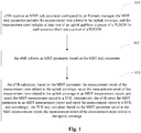
- a method for obtaining and reporting a measurement result of a measurement item related to an uplink coverage includes steps 101 to 103.
- eNB receives an MDT task parameter configured by an element manager.
- the MDT task parameter includes the measurement item related to the uplink coverage.
- the measurement item includes at least one of an uplink pathloss, a power of a PUSCH for each resource block and a power of a PUCCH.
- the element manager may configure, through a network management interface, the MDT task parameter for the eNB when creating an immediate MDT task.
- the MDT task parameter includes the measurement item related to the uplink coverage, and the measurement item includes at least one of the uplink pathloss, the power of the PUSCH for each resource block and the power of the PUCCH.
- the MDT task parameter configured by the element manager may be received by the eNB.
- the measurement item related to the uplink coverage may further include a power headroom.
- the eNB collects an MDT parameter based on the MDT task parameter.
- the eNB may collect, based on the MDT task parameter, the MDT parameter from parameters related to MDT UE.
- the MDT parameter may include, for example, a maximum available output power P CMAX of the UE, the number M PUSCH ( i ) of resource block(s) validated in an ith frame and allocated for the PUSCH, an initial value P O_PUSCH ( j ) of the power of the PUSCH of the UE, a compensation factor ⁇ ( j ) of the pathloss, an adjustment ⁇ TF ( i ) for the power based on a modulation and coding scheme (MCS) of the ith frame, and a correction value f ( i ) based on a Transmission Power Control (TPC) command in case of the ith frame.
- MCS modulation and coding scheme
- j represents a preset transmission approach. In the case that j equals 0, it is indicated that a PUSCH transmission carrying persistent scheduling and non-adaptive retransmission is applied. In the case that j equals to 1, it is indicated that a PUSCH transmission carrying dynamic scheduling and adaptive retransmission is applied. In the case that j equals to 2, it is indicated that a PUSCH transmission carrying a random access message 3 is applied.
- the type of the MDT parameter needed to be collected may be determined based on the measurement item related to the uplink coverage, which is detailed according to the following aspects and is not described here.
- the eNB may choose an UE for performing the minimized drive test, i.e., the MDT UE, after receiving the MDT parameter configured by the element manager.
- the eNB may choose all or a few of the UE in a coverage of the eNB as the MDT UE. It should be noted that, unless specified otherwise, the UE referred to in the embodiment of the disclosure means the MDT UE.
- the UE in the coverage of the eNB may report a parameter of the UE itself to the eNB.
- the eNB may choose the UE and then perform, based on the MDT task parameter, a parameter collection from the parameter reported by the chosen UE.
- the eNB may configure the MDT task parameter and then send the configured MDT task parameter to the chosen UE.
- the chosen MDT UE performs, based on the MDT task parameter, a parameter collection and then reports the collected MDT parameter to the eNB.
- the eNB calculates, based on the MDT parameter, the measurement result of the measurement item related to the uplink coverage, saves the measurement result of the measurement item related to the uplink coverage in an MDT measurement report, and sends the MDT measurement report to a trace collection entity TCE.
- the eNB saves the MDT parameter in the MDT measurement report and sends the measurement report to the TCE, and accordingly, the TCE may calculate, based on the MDT parameter saved in the MDT measurement report, the measurement result of the measurement item related to the uplink coverage.
- the eNB may calculate the measurement result of the measurement item related to the uplink coverage based on the MDT parameter, save the measurement result of the measurement item related to the uplink coverage in the MDT measurement report, and send the MDT measurement report to the TCE. Accordingly, the TCE may obtain the measurement result of the measurement item related to the uplink coverage of the UE.
- the eNB may save the MDT parameter in the MDT measurement report and send the MDT measurement report to the TCE. Accordingly, the TCE may calculate, based on the MDT parameter saved in the MDT measurement report, the measurement result of the measurement item related to the uplink coverage.
- the MDT task parameter configured by the element manager and received by the eNB includes the measurement item related to the uplink coverage.
- the eNB may collect the MDT parameter based on the MDT task parameter, calculate based on the MDT parameter the measurement result of the measurement item related to the uplink coverage, and send the measurement result of the measurement item related to the uplink coverage to the TCE.
- the eNB sends the MDT parameter to the TCE, and accordingly, the TCE calculates, based on the MDT parameter, the measurement result of the measurement item related to the uplink coverage.
- the measurement item related to the uplink coverage includes at least one of the power headroom, the uplink pathloss, the power of the PUSCH for each resource block and the power of the PUCCH, the uplink pathloss or an uplink interference of the UE may be precisely determined by a coverage optimization application in the TCE layer, to precisely identify the problem in the uplink coverage of the UE.
- a method for obtaining and reporting a measurement result of a measurement item related to an uplink coverage according to the disclosure includes steps 201 to 204.
- eNB receives an MDT task parameter configured by an element manager.
- the MDT task parameter includes the measurement item related to the uplink coverage, and the measurement item includes at least one of an uplink pathloss, a power of a PUSCH for each resource block and a power of a PUCCH.
- the eNB collects an MDT parameter based on the MDT task parameter.
- the measurement item related to the uplink coverage may further include a power headroom.
- the eNB calculates, based on the MDT parameter, the measurement result of the measurement item related to the uplink coverage, and saves a correspondence among the measurement result, a serial number of a resource block of the UE and location information of the UE, in an MDT measurement report.
- the eNB saves a parameter, which is included in the MDT parameter and is used for calculating the measurement result of the measurement item related to the uplink coverage, in the MDT measurement report.
- the eNB may calculate the measurement result of the measurement item related to the uplink coverage based on the MDT parameter.
- the measurement item related to the uplink coverage includes at least one of the uplink pathloss, the power of the PUSCH for each resource block and the power of the PUCCH.
- the measurement item related to the uplink coverage may further include the power headroom.
- the eNB collects a downlink reference signal receiving power (RSRP) and calculates a downlink pathloss based on the RSRP.
- RSRP downlink reference signal receiving power
- FDD Frequency Division Duplexing
- TDD Time Division Duplexing
- j may be set as at least one of 0, 1 or 2. In the case that j equals to 0, it is indicated that a PUSCH transmission carrying a persistent scheduling and a non-adaptive retransmission is applied. In the case that j equals to 1, it is indicated that a PUSCH transmission carrying a dynamic scheduling and an adaptive retransmission is applied. In the case that j equals to 2, it is indicated that a PUSCH transmission carrying a random access message 3 is applied. In practice, j may be set based on conditions.
- j may be set as 0 and 1 to calculate compensation factors for the pathloss, and accordingly, a compensation factor ⁇ (0) in case of the PUSCH transmission carrying the persistent scheduling and the non-adaptive retransmission, and a compensation factor ⁇ (1) in case of the PUSCH transmission carrying the dynamic scheduling and the adaptive retransmission may be obtained.
- the UE may send a power headroom report including the PH to the eNB through an air interface following the MAC protocol, and accordingly, eNB obtains the PH of the UE.
- Other parameters such as M PUSCH ( i ), P O_PUSH ( j ), ⁇ ( j ) , j, ⁇ TF ( i ) and f ( i ) are MDT parameters or are set by eNB.
- P CMAX is preset by eNB.
- UE may send P CMAX to eNB, and accordingly, eNB may calculate the downlink pathloss of the UE with the equation (1).
- the uplink pathloss of the UE is determined as being equal to a sum of the calculated downlink pathloss of the UE and a preset correction value in the case that the UE is located in an FDD network, or the uplink pathloss of the UE is determined as being equal to the downlink pathloss of the UE in the case that the UE is located in a TDD network.
- powers of the PUSCH for each resource block calculated with the equations (2) to (5) have different representations from each other.
- P RB_PUSCH is calculated with the equation (2)
- both an effect of the MCS and an effect of the TPC are taken into consideration.
- P RB_PUSCH is calculated with the equation (3)
- the effect of the MCS is taken into consideration while the effect of TPC is not.
- P RB_PUSCH is calculated with the equation (4)
- neither the effect of the MCS nor the effect of the TPC is taken into consideration.
- P RB_PUSCH is calculated with the equation (5), the effect of the TPC is taken into consideration while the effect of the MCS is not.
- P RB_PUSCH in the equation (6) or the equation (7) may be obtained with any one of the equations (2) to (5), which may be chosen based on conditions and is not limited here.
- the UE may calculate the power of the PUSCH for each resource block with any one of the equations (2) to (5), and then calculate the power headroom with the equation (6) or the equation (7).
- the power headroom may be obtained with other approaches.
- UE sends a power headroom report including the PH to the eNB through an air interface following the MAC protocol, and accordingly, eNB extracts PH from the report.
- eNB may collect a downlink RSRP of the UE and calculate PH of the UE based on the RSRP.
- P PUCCH represents the power of the PUCCH
- P O_PUCCH represents an initial value of the power of the PUCCH
- g ( i ) represents a correction value based on a TPC command in case of an ith frame
- P CMAX represents a maximum available output power of the UE
- both h ( n CQI ,n HARQ ) and ⁇ F_PUCCH ( F ) represent correction values based on a format of the PUC
- powers of the PUCCH calculated with the equations (8) to (10) have different representations from each other.
- the power of the PUCCH is calculated with the equation (8)
- an effect of the TPC is taken into consideration while an effect of the format of the PUCCH is not.
- the power of the PUCCH is calculated with the equation (9)
- neither the effect of the format of the PUCCH nor the effect of the TPC is taken into consideration.
- the power of the PUCCH is calculated with the equation (10)
- both the effect of the TPC and the effect of the format of the PUCCH are taken into consideration.
- at least one of the equations (8) to (10) may be chosen to obtain the corresponding P PUCCH , which is not limited here.
- the measurement item related to the uplink coverage includes at least one of the uplink pathloss, the power of the PUSCH for each resource block and the power of the PUCCH.
- eNB may choose corresponding approach(es) based on the specific parameter included in the measurement item related to the uplink coverage to obtain the measurement result of the parameter. For example, in the case that the measurement item related to the uplink coverage includes the uplink pathloss and the power of the PUSCH for each resource block, eNB calculates the measurement results of the uplink pathloss and the power of the PUSCH for each resource block with the approaches described in 1) and 2) .
- eNB may save the obtained measurement result of the measurement item related to the uplink coverage in the MDT measurement report.
- eNB may further save a correspondence among the measurement result of the measurement item related to the uplink coverage, a serial number of a resource block of the UE and location information of the UE, in the MDT measurement report.
- the serial number of the resource block of the UE and the location information of the UE are both MDT parameters.
- eNB may further save a parameter, which is included in the MDT parameter and is used for calculating the measurement item related to the uplink coverage, in the MDT measurement report, and accordingly, a TCE receiving the MDT measurement report may extract the parameter for calculating the measurement item related to the uplink coverage and obtain the measurement result of the measurement item related to the uplink coverage based on the parameter.
- the parameter for calculating the measurement item related to the uplink coverage includes at least one of the maximum available output power P CMAX of the UE, the number M PUSCH ( i ) of the resource block(s) validated in the ith frame and allocated for the PUSCH, the initial value P O_PUSCH ( j ) of the power of the PUSCH, the compensation factor ⁇ ( j ) for the pathloss, the preset transmission approach j, the adjustment ⁇ TF ( i ) for the power based on the modulation and coding scheme MCS of the ith frame, the correction value f ( i ) based on the Transmission Power Control TPC command in case of the ith frame, the initial value P O_PUCCH of the power of the PUCCH, and the correction values h ( n CQI ,n HARQ ) and ⁇ F_PUCCH ( F ) based on the format of the PUCCH.
- the specific type of the parameter for calculating the measurement item related to the uplink coverage is associated with the type of the measurement item related to the uplink coverage and specific approaches for calculating.
- the type of the parameter for calculating the measurement item related to the uplink coverage may be determined based on conditions, which is not limited here.
- the TCE may calculate the measurement item related to the uplink coverage with the approaches described in 1) to 4), which is not limited here.
- the MDT measurement report is sent to the TCE.
- eNB sends the MDT measurement report to the TCE, and accordingly, the TCE may extract, from the MDT measurement report, the measurement result of the measurement item related to the uplink coverage.
- the TCE calculates the measurement result of the measurement item related to the uplink coverage, based on the parameter for calculating the measurement result of the measurement item related to the uplink coverage included in the MDT measurement report.
- eNB may perform, according to the MDT task parameter, a parameter collection from parameters related to MDT UE, obtain, based on the collected MDT parameter, the measurement result of the measurement item related to the uplink coverage, and send the MDT measurement report including the measurement result of the measurement item related to the uplink coverage, to the TCE.
- eNB may save the MDT parameter in the MDT measurement report to send the MDT measurement report to the TCE, and accordingly, the TCE calculates, based on the MDT parameter, the measurement result of the measurement item related to the uplink coverage.
- a coverage optimization application in a TCE layer may determine the uplink pathloss and an uplink interference of the UE precisely, to precisely identify a problem in the uplink coverage of the UE.
- FIG. 1 and Figure 2 it is described the methods for eNB to obtain and report the measurement result of the measurement item related to the uplink coverage in the case that the measurement item included in the MDT task parameter includes at least one of the uplink pathloss, the power of the PUSCH for each resource block and the power of the PUCCH.
- a method for the eNB to obtain and report a measurement result of a measurement item related to an uplink coverage in the case that the measurement item included in an MDT task parameter includes a power headroom is described hereinafter.
- a method for obtaining and reporting a measurement result of a measurement item related to an uplink coverage as shown in Figure 3 includes steps 301 to 303.
- an eNB receives an MDT task parameter configured by an element manager.
- the MDT task parameter includes a first measurement item related to the uplink coverage.
- the first measurement item includes a power headroom.
- eNB may receive the MDT task parameter configured by the element manager.
- the MDT task parameter includes the first measurement item related to the uplink coverage.
- the first measurement item is the power headroom.
- eNB collects an MDT parameter based on the MDT task parameter.
- eNB collects the MDT parameter based on the MDT task parameter.
- eNB may collect, the MDT parameter from parameters related to MDT UE based on the MDT task parameter.
- the MDT parameter may include, for example, a maximum available output power P CMAX of the UE, the number M PUSCH ( i ) of resource block(s) validated in an ith frame and allocated for the PUSCH, an initial value P O_ PUSCH ( j ) of the power of the PUSCH of the UE, a compensation factor ⁇ ( j ) of the pathloss, an adjustment ⁇ TF ( i ) for the power based on a modulation and coding scheme (MCS) of the ith frame, and a correction value f ( i ) based on a Transmission Power Control (TPC) command in case of the ith frame.
- MCS modulation and coding scheme
- j represents a preset transmission approach. In the case that j equals 0, it is indicated that a PUSCH transmission carrying a persistent scheduling and a non-adaptive retransmission is applied. In the case that j equals to 1, it is indicated that a PUSCH transmission carrying a dynamic scheduling and an adaptive retransmission is applied. In the case that j equals to 2, it is indicated that a PUSCH transmission carrying a random access message 3 is applied.
- eNB calculates, based on the MDT parameter, the measurement results of the first measurement item and a preset second measurement item related to the uplink coverage, saves the measurement results of the first measurement item and the second measurement item in an MDT measurement report, and sends the MDT measurement report to a TCE.
- eNB saves the MDT parameter in an MDT measurement report and sends the measurement report to a TCE, and accordingly, the TCE may calculate, based on the MDT parameter saved in the MDT measurement report, the measurement results of the first measurement item and the second measurement item.
- the second measurement item includes at least one of an uplink pathloss, a power of a PUSCH for each resource block and a power of a PUCCH.
- the second measurement item related to the uplink coverage may be preset in eNB.
- the uplink pathloss and an uplink interference of the UE may be determined by a coverage optimization application in a TCE layer based on the measurement result of the second measurement item and the measurement result of the first measurement item which is configured in a first MDT task parameter.
- the second measurement item includes at least one of the uplink pathloss, the power of the PUSCH for each resource block and the power of the PUCCH.
- eNB may calculate the measurement results of the first measurement item and the second measurement item based on the collected MDT parameter.
- An approach for obtaining the measurement result of the first measurement item, i.e., the power headroom, is similar as the approach described in 2) in connected with the step 203 shown in Figure 2 , which is not detailed here.
- an approach for eNB to obtain the measurement result of the uplink pathloss is similar as the approach described in 1) in connecting with the step 203 shown in Figure 2 , which is not detailed here.
- an approach for eNB to obtain the measurement result of the power of the PUSCH for each resource block is similar as the approach described in 2) in connection with the step 203 shown in Figure 2 , which is not detailed here.
- an approach for eNB to obtain the measurement result of the power of the PUCCH is similar as the approach described in 4) of in connection with the step 203 shown in Figure 2 , which is not detailed here.
- eNB may save the MDT parameter in the MDT measurement report and send the MDT measurement report to the TCE, and accordingly, the TCE may calculate the measurement results of the first measurement item and the second measurement item based on the MDT parameter saved in the MDT measurement report.
- the TCE may use the approaches described in 1) to 10) to calculate the corresponding measurement items related to the uplink coverage, which is not detailed here.
- eNB may calculate the measurement results of the first measurement item and the second measurement item after collecting the MDT parameter and send the measurement results to the TCE.
- eNB sends the MDT parameter to the TCE, and accordingly, the TCE calculates, based on the MDT parameter, the measurement results of the first measurement item and the second measurement item.
- the second measurement item includes at least one of the uplink pathloss, the power of the PUSCH for each resource block and the power of the PUCCh, the uplink pathloss and an uplink interference of the UE may be precisely determined with a coverage optimization application in a TCE layer, to precisely identify a problem in the uplink coverage of the UE.
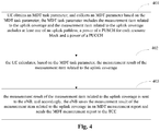
- the method for obtaining and reporting the measurement result of the measurement item related to the uplink coverage is described from the side of eNB in conjunction with Figures 1-3 .
- the method for obtaining and reporting the measurement result of the measurement item related to the uplink coverage is described from the side of the UE.
- the method includes steps 401 to 403.
- UE obtains an MDT task parameter, and collects an MDT parameter based on the MDT task parameter.
- the MDT task parameter includes the measurement item related to the uplink coverage.
- the measurement item related to the uplink coverage includes at least one of an uplink pathloss, a power of a PUSCH for each resource block and a power of a PUCCH.
- an element manager may configure, through a network management interface, the MDT task parameter for an eNB.
- the MDT task parameter includes the measurement item related to the uplink coverage.
- the measurement item related to the uplink coverage includes at least one of the uplink pathloss, the power of the PUSCH for each resource block and the power of the PUCCH.
- the measurement item related to the uplink coverage may further include a power headroom.
- the eNB sends the MDT task parameter to the MDT UE, and accordingly, the UE may obtain the MDT task parameter and collect the MDT parameter based on the MDT task parameter.
- the UE calculates, based on the MDT task parameter, the measurement result of the measurement item related to the uplink coverage.
- the UE calculates, based on the MDT task parameter, the measurement result of the measurement item related to the uplink coverage. 5) In the case that the measurement item related to the uplink coverage includes the uplink pathloss, the UE may calculate the uplink pathloss with any one of the following approaches C and D.
- the UE obtains a downlink RSRP and calculates a downlink pathloss based on the RSRP.
- the uplink pathloss of the UE equals to a sum of the calculated downlink pathloss and a preset correction value.
- the uplink pathloss equals to the calculated downlink pathloss.
- j may be set as at least one of 0, 1 or 2. In the case that j equals to 0, it is indicated that a PUSCH transmission carrying a persistent scheduling and a non-adaptive retransmission is applied. In the case that j equals to 1, it is indicated that a PUSCH transmission carrying a dynamic scheduling and an adaptive retransmission is applied. In the case that j equals to 2, it is indicated that a PUSCH transmission carrying a random access message 3 is applied. In practice, j may be set based on conditions.
- j may be set as 0 and 1 to calculate compensation factors for the pathloss, and accordingly, a compensation factor ⁇ (0) in case of the PUSCH transmission carrying the persistent scheduling and the non-adaptive retransmission, and a compensation factor ⁇ (1) in case of the PUSCH transmission carrying the dynamic scheduling and the adaptive retransmission may be obtained.
- the UE determines that the uplink pathloss equals to a sum of the obtained downlink pathloss and the preset correction value in the case that the UE is located in the FDD network, or the UE determined that the uplink pathloss equals to the downlink pathloss in the case that the UE is located in the TDD network.
- powers of the PUSCH for each resource block calculated with the equations (2) to (5) have different representations from each other.
- P RB_PUSCH is calculated with the equation (2)
- both an effect of the MCS and an effect of the TPC are taken into consideration.
- P RB_PUSCH is calculated with the equation (3)
- the effect of the MCS is taken into consideration while the effect of TPC is not.
- P RB_PUSCH is calculated with the equation (4)
- neither the effect of the MCS nor the effect of the TPC is taken into consideration.
- P RB_PUSCH is calculated with the equation (5), the effect of the TPC is taken into consideration while the effect of the MCS is not.
- P RB_PUSCH in the equation (6) or the equation (7) may be obtained with any one of the equations (2) to (5), which may be chosen based on conditions and is not limited here.
- the UE may calculate the power of the PUSCH for each resource block with any one of the equations (2) to (5), and then calculate the power headroom with the equation (6) or the equation (7).
- the power headroom may be obtained with other approaches.
- the UE calculates PH of the UE based on a downlink RSRP of the UE. 8)
- P PUCCH represents the power of the PUCCH
- P O_PUCCH represents an initial value of the power of the PUCCH
- g(i) represents a correction value based on a TPC command in case of an ith frame
- P CMAX represents a maximum
- powers of the PUCCH calculated with the equations (8) to (10) have different representations from each other.
- the power of the PUCCH is calculated with the equation (8)
- an effect of the TPC is taken into consideration while an effect of the format of the PUCCH is not.
- the power of the PUCCH is calculated with the equation (9)
- neither the effect of the format of the PUCCH nor the effect of the TPC is taken into consideration.
- the power of the PUCCH is calculated with the equation (10)
- both the effect of the TPC and the effect of the format of the PUCCH are taken into consideration.
- at least one of the equations (8) to (10) may be chosen to obtain the corresponding P PUCCH , which is not limited here.
- the measurement item related to the uplink coverage includes at least one of the uplink pathloss, the power of the PUSCH for each resource block and the power of the PUCCH.
- the UE may choose corresponding approach(es) based on the specific parameter included in the measurement item related to the uplink coverage to obtain the measurement result of the parameter. For example, in the case that the measurement item related to the uplink coverage includes the uplink pathloss and the power of the PUSCH for each resource block, the UE calculates the measurement results of the uplink pathloss and the power of the PUSCH for each resource block with the approaches described in 5) and 6).
- the measurement result of the measurement item related to the uplink coverage is sent to eNB, and accordingly, eNB saves the measurement result of the measurement item related to the uplink coverage in an MDT measurement report and sends the MDT measurement report to the TCE.
- the UE sends the measurement result of the measurement item related to the uplink coverage to eNB after obtaining the measurement result of the measurement item related to the uplink coverage. Accordingly, eNB saves the measurement result in the MDT measurement report and sends the MDT measurement report to the TCE.
- the UE collects the MDT parameter based on the MDT task parameter, calculates, based on the collected MDT parameter, the measurement result of the measurement item related to the uplink coverage, and sends the measurement result to eNB. Accordingly, eNB may save the measurement result in the MDT measurement report to send the MDT measurement report to the TCE.
- the measurement item related to the uplink coverage includes at least one of the power headroom, the uplink pathloss, the power of the PUSCH for each resource block and the power of the PUCCH, the uplink pathloss and an uplink interference of the UE may be precisely determined with a coverage optimization application in a TCE layer, to precisely identify a problem in the uplink coverage of the UE.
- a device for executing a method for obtaining and reporting a measurement result of a measurement item related to an uplink coverage includes:
- Figure 5 shows a base station according to an embodiment of the disclosure including a processor 501 and a sender 502.
- the processor 501 is adapted for obtaining an MDT parameter, and calculating, based on the MDT parameter, a measurement result of a measurement item related to an uplink coverage.
- the measurement item related to the uplink coverage includes at least one of an uplink pathloss, a power of a PUSCH for each resource block and a power of a PUCCH.
- the sender 502 is adapted for sending the measurement result of the measurement item related to the uplink coverage after the measurement result of the measurement item related to the uplink coverage is calculated by the processor.
- the processor 501 includes:
- the measurement item related to the uplink coverage includes at least one of the uplink pathloss, the power of the PUSCH for each resource block and the power of the PUCCH.
- the measurement item related to the uplink coverage may further include a power headroom.
- the first calculating unit 504 collects a downlink RSRP of UE and calculates a downlink pathloss of the UE based on the RSRP.
- the uplink pathloss of the UE equals to a sum of the obtained downlink pathloss and a preset correction value.
- the uplink pathloss of the UE equals to the downlink pathloss of the UE.
- j may be set as at least one of 0, 1 or 2. In the case that j equals to 0, it is indicated that a PUSCH transmission carrying a persistent scheduling and a non-adaptive retransmission is applied. In the case that j equals to 1, it is indicated that a PUSCH transmission carrying a dynamic scheduling and an adaptive retransmission is applied. In the case that j equals to 2, it is indicated that a PUSCH transmission carrying a random access message 3 is applied. In practice, j may be set based on conditions.
- j may be set as 0 and 1 to calculate compensation factors for the pathloss, and accordingly, a compensation factor ⁇ (0) in case of the PUSCH transmission carrying the persistent scheduling and the non-adaptive retransmission, and a compensation factor ⁇ (1) in case of the PUSCH transmission carrying the dynamic scheduling and the adaptive retransmission may be obtained.
- the UE may send a power headroom report including the PH to the eNB through an air interface following the MAC protocol, and accordingly, eNB obtains PH of the UE.
- Other parameters such as M PUSCH ( i ), P O_PUSCH ( j ), ⁇ ( j ) , j, ⁇ TF ( i ) and f ( i ) are MDT parameters or are set by eNB.
- P CMAX is preset by eNB.
- the UE may send P CMAX to eNB, and accordingly, eNB may calculate the downlink pathloss of the UE with the equation (1).
- the first calculating unit 504 determines that the uplink pathloss of the UE equals to a sum of the obtained downlink pathloss of the UE and a preset correction value in the case that the UE is located in an FDD network, or the first calculating unit 504 determines that the uplink pathloss of the UE equals to the downlink pathloss of the UE in the case that the UE is located in a TDD network.
- powers of the PUSCH for each resource block calculated with the equations (2) to (5) have different representations from each other.
- P RB_PUSCH is calculated with the equation (2)
- both an effect of the MCS and an effect of the TPC are taken into consideration.
- P RB_PUSCH is calculated with the equation (3)
- the effect of the MCS is taken into consideration while the effect of TPC is not.
- P RB_PUSCH is calculated with the equation (4)
- neither the effect of the MCS nor the effect of the TPC is taken into consideration.
- P RB_PUSCH is calculated with the equation (5), the effect of the TPC is taken into consideration while the effect of the MCS is not.
- P RB_PUSCH in the equation (6) or the equation (7) may be obtained with any one of the equations (2) to (5), which may be chosen based on conditions and is not limited here.
- the first calculating unit 504 may calculate the power of the PUSCH for each resource block with any one of the equations (2) to (5), and then calculate the power headroom with the equation (6) or the equation (7).
- the power headroom may be obtained with other approaches.
- the first calculating unit 504 may collect a downlink RSRP of the UE and calculate PH of the UE based on the RSRP.
- P PUCCH represents the power of the PUCCH
- P O_PUCCH represents an initial value of the power of the PUCCH
- g ( i ) represents a correction value based on a TPC command in case of an ith frame
- P CMAX represents a maximum available output power of the UE
- both h ( n CQI, n HARQ ) and ⁇ F_PUCCH ( F ) represent correction values based on a format of the PUCCH
- powers of the PUCCH calculated with the equations (8) to (10) have different representations from each other.
- the power of the PUCCH is calculated with the equation (8)
- an effect of the TPC is taken into consideration while an effect of the format of the PUCCH is not.
- the power of the PUCCH is calculated with the equation (9)
- neither the effect of the format of the PUCCH nor the effect of the TPC is taken into consideration.
- the power of the PUCCH is calculated with the equation (10)
- both the effect of the TPC and the effect of the format of the PUCCH are taken into consideration.
- at least one of the equations (8) to (10) may be chosen to obtain the corresponding P PUCCH , which is not limited here.
- the MDT task parameter configured by the EM and received by eNB includes the measurement item related to the uplink coverage; eNB collects the MDT parameter based on the MDT task parameter, calculates, based on the MDT parameter, the measurement result of the measurement item related to the uplink coverage, and sends the measurement result of the measurement item related to the uplink coverage to the TCE.
- the measurement item related to the uplink coverage includes at least one of the power headroom, the uplink pathloss, the power of the PUSCH for each resource block and the power of the PUCCH, the uplink pathloss and an uplink interference of the UE may be precisely determined with a coverage optimization application in a TCE layer to precisely identify a problem in the uplink coverage of the UE.
- Figure 6 shows a base station according to an embodiment of the disclosure including a processor 601 and a sender 602.
- the processor 601 is adapted for obtaining an MDT parameter, saving the MDT parameter in an MDT measurement report and sending the MDT measurement report to a trace collection entity TCE. Accordingly, the TCE obtains the MDT parameter from the received MDT measurement report and calculates, based on the MDT parameter, a measurement result of a measurement item related to an uplink coverage.
- the measurement item related to the uplink coverage includes at least one of an uplink pathloss, a power of a PUSCH for each resource block and a power of a PUCCH.
- the sender 602 is adapted for sending the MDT measurement report after the MDT parameter is obtained and saved to the MDT measurement report by the processor.
- the processor 601 includes:
- the MDT task parameter configured by the EM and received by eNB includes the measurement item related to the uplink coverage; eNB collects the MDT parameter based on the MDT task parameter, saves the MDT parameter in the MDT measurement report and sends the MDT measurement report to eNB. Since the measurement item related to the uplink coverage includes at least one of the power headroom, the uplink pathloss, the power of the PUSCH for each resource block and the power of the PUCCH, the uplink pathloss and an uplink interference of the UE may be precisely determined with a coverage optimization application in the TCE layer to precisely identify a problem in the uplink coverage of the UE.
- UE provided according to an example of the disclosure includes a processor 701 and a sender 702.
- the processor 701 is adapted for obtaining an MDT parameter, and calculating, based on the MDT parameter, a measurement result of a measurement item related to an uplink coverage.
- the measurement item related to the uplink coverage includes at least one of an uplink pathloss, a power of a PUSCH for each resource block and a power of a PUCCH.
- the sender 702 is adapted for sending the measurement result of the measurement item related to the uplink coverage after the measurement result of the measurement item related to the uplink coverage is calculated by the processor.
- the processor 701 includes:
- the second calculating unit 704 may obtain a value of the uplink pathloss with any one of the two approaches described as follows.
- the second calculating unit 704 calculates a downlink pathloss based on a downlink RSRP.
- the UE determines that the uplink pathloss of the UE equals to a sum of the obtained downlink pathloss and a preset correction value.
- the UE determines that the uplink pathloss equals to the obtained downlink pathloss.
- j may be set as at least one of 0, 1 or 2. In the case that j equals to 0, it is indicated that a PUSCH transmission carrying a persistent scheduling and a non-adaptive retransmission is applied. In the case that j equals to 1, it is indicated that a PUSCH transmission carrying a dynamic scheduling and an adaptive retransmission is applied. In the case that j equals to 2, it is indicated that a PUSCH transmission carrying a random access message 3 is applied. In practice, j may be set based on conditions.
- j may be set as 0 and 1 to calculate compensation factors for the pathloss, and accordingly, a compensation factor ⁇ (0) in case of the PUSCH transmission carrying the persistent scheduling and the non-adaptive retransmission, and a compensation factor ⁇ (1) in case of the PUSCH transmission carrying the dynamic scheduling and the adaptive retransmission may be obtained.
- the second calculating unit 704 determines that the uplink pathloss equals to a sum of the obtained downlink pathloss and the preset correction value in the case that the UE is located in the FDD network, or the second calculating unit 704 determines that the uplink pathloss equals to the downlink pathloss in the case that the UE is located in the TDD network.
- powers of the PUSCH for each resource block calculated with the equations (2) to (5) have different representations from each other.
- P RB_PUSCH is calculated with the equation (2)
- both an effect of the MCS and an effect of the TPC are taken into consideration.
- P RB_PUSCH is calculated with the equation (3)
- the effect of the MCS is taken into consideration while the effect of TPC is not.
- P RB_PUSCH is calculated with the equation (4)
- neither the effect of the MCS nor the effect of the TPC is taken into consideration.
- P RB_PUSCH is calculated with the equation (5), the effect of the TPC is taken into consideration while the effect of the MCS is not.
- P RB_PUSCH in the equation (6) or the equation (7) may be obtained with any one of the equations (2) to (5), which may be chosen based on conditions and is not limited here.
- the second calculating unit 704 may calculate the power of the PUSCH for each resource block with any one of the equations (2) to (5), and then calculate the power headroom with the equation (6) or the equation (7).
- the power headroom may be obtained with other approaches.
- the second calculating unit 704 may calculate PH of the UE based on the downlink RSRP.
- P PUCCH represents the power of the PUCCH
- P O_PUCCH represents an initial value of the power of the PUCCH
- g ( i ) represents a correction value based on a TPC command in case of an ith frame
- P CMAX represents a maximum available output power of the UE
- both h ( n CQI , n HARQ ) and ⁇ F_PUCCH ( F ) represent correction values based on a format of the PUC
- powers of the PUCCH calculated with the equations (8) to (10) have different representations from each other.
- the power of the PUCCH is calculated with the equation (8)
- an effect of the TPC is taken into consideration while an effect of the format of the PUCCH is not.
- the power of the PUCCH is calculated with the equation (9)
- neither the effect of the format of the PUCCH nor the effect of the TPC is taken into consideration.
- the power of the PUCCH is calculated with the equation (10)
- both the effect of the TPC and the effect of the format of the PUCCH are taken into consideration.
- at least one of the equations (8) to (10) may be chosen to obtain the corresponding P PUCCH , which is not limited here.
- the measurement item related to the uplink coverage includes at least one of the uplink pathloss, the power of the PUSCH for each resource block and the power of the PUCCH.
- the measurement item related to the uplink coverage may further include the power headroom but may not include only the power headroom.
- the UE may choose corresponding approach(es) based on the specific parameter included in the measurement item related to the uplink coverage, to obtain the measurement result of the parameter.
- the second calculating unit 704 calculates the measurement results of the uplink pathloss and the power of the PUSCH for each resource block with the approaches described in 5) and 6).
- the UE collects the MDT parameter based on the MDT task parameter, calculates the measurement result of the measurement item related to the uplink coverage based on the collected MDT parameter, and sends the measurement result to eNB. Accordingly, eNB may save the measurement result in the MDT measurement report to send the MDT measurement report to the TCE.
- the measurement item related to the uplink coverage includes at least one of the power headroom, the uplink pathloss, the power of the PUSCH for each resource block and the power of the PUCCH, the uplink pathloss and an uplink interference of the UE may be precisely determined with a coverage optimization application in a TCE layer, to precisely identify a problem in the uplink coverage of the UE.
- the programs may be stored in a computer readable storage medium.
- the storage medium may be a Read Only Memory, a magnetic disk, a Compact Disk, etc.
Landscapes
- Engineering & Computer Science (AREA)
- Computer Networks & Wireless Communication (AREA)
- Signal Processing (AREA)
- Mobile Radio Communication Systems (AREA)
Claims (10)
- Verfahren zum Erhalt und Reporting eines Messergebnisses eines Messartikels in Bezug auf eine Uplink-Abdeckung, umfassend:Einholen (101, 102) eines minimierten Steuerungstest- MDT -Parameters durch einen entwickelten Knoten B, eNB;Berechnen (103) des Messergebnisses des Messartikels durch den eNB in Bezug auf der Uplink-Abdeckung, die auf dem MDT-Parameter basiert, und Senden des Messergebnisses des Messartikels an eine Spurerfassungseinheit TCE in Bezug auf die Uplink-Abdeckung;wobei der Messartikel in Bezug auf die Uplink-Abdeckung eine Leistung eines Physischen Uplink-Geteilten Kanals PUSCH für jeden Ressourcenblock umfasst; oderAbspeichern (103) des MDT-Parameters durch den eNB in einem MDT-Messbericht und Senden des MDT-Messberichts an die TCE, wobei die TCE den MDT-Parameter von dem eingeholten MDT-Messbericht einholt und das Messergebnis des Messartikels in Bezug auf die Uplink-Abdeckung, die auf dem MDT-Parameter basiert, berechnet; wobei der Messartikel in Bezug auf die Uplink-Abdeckung eine Leistung eines PUSCHs für jeden Ressourcenblock umfasst;wobei der MDT-Parameter einen Anfangswert P O_PUSCH (j) der Leistung des PUSCHs, einen Kompensationsfaktor α(j) eines Pfadverlustes, einen voreingestellten Übertragungsansatz j, eine Anpassung ΔTF (i) für eine Leistung, die auf einem Modulations- und Codierungsschema MSC eines i-ten Frames basiert, und einen Korrekturwert f(i), der auf einem Übertragungs-Energie-Kontroll- TPC -Befehl basiert für den Fall des i-ten Frames, umfasst, für den Fall, dass j gleich 0 ist, ist angegeben, dass eine PUSCH-Übertragung, die eine fortbestehende Ablaufplanung und eine nicht adaptive Rückübertragung trägt, angewendet ist; für den Fall, dass j gleich 1 ist, ist angegeben, dass eine PUSCH-Übertragung, die eine dynamische Ablaufplanung und adaptive Rückübertragung trägt, angewendet ist und für den Fall, dass j gleich 2 ist, ist angegeben, dass eine PUSCH-Übertragung, die eine zufällige Zugangsmeldung trägt, angewendet ist;wobei die Berechnung des Messergebnisses des Messartikels in Bezug auf die Uplink-Abdeckung, die auf dem MDT-Parameter basiert, umfasst:
Berechnen der Leistung des PUSCHs für jeden Ressourcenblock mit wenigstens einer der folgenden Gleichungen:


- Verfahren nach Anspruch 1, wobei das Einholen des minimierten Steuerungstest- MDT - Parameters durch den eNB umfasst:Empfangen (201) eines MDT-Aufgabenparameters, der durch einen Elementmanager EM konfiguriert ist, und Erfassen des MDT-Parameters, der auf dem MDT-Aufgabenparameter basiert, durch den eNB;wobei das Berechnen des Messergebnisses des Messartikels in Bezug auf die Uplink-Abdeckung auf dem MDT-Parameter basiert und das Senden des Messergebnisses des Messartikels in Bezug auf die Uplink-Abdeckung umfasst:Berechnen (203) des Messergebnisses des Messartikels durch den eNB in Bezug auf die Uplink-Abdeckung, die auf dem MDT-Parameter basiert;Abspeichern (203) des Messergebnisses des Messartikels durch den eNB in Bezug auf die Uplink-Abdeckung in einem MDT-Messbericht; undSenden (204) des MDT-Messberichts durch den eNB an die TCE.
- Verfahren nach irgendeinem der Ansprüche 1 bis 2, wobei der Messartikel in Bezug auf die Uplink-Abdeckung weiterhin eine Leistungsbauhöhe umfasst, der MDT-Parameter eine maximale verfügbare Ausgabeleistung P CMAX einer Nutzerausrüstung UE, eine Leistungsklasse P POWERCLASS der UE umfasst;
wobei die Berechnung des Messergebnisses des Messartikels in Bezug auf die Uplink-Abdeckung, die auf dem MDT-Parameter basiert, umfasst:
Berechnen der Leistungsbauhöhe mit wenigstens einer der folgenden Gleichungen:

- Verfahren nach irgendeinem der Ansprüche 1-3, wobei der Messartikel in Bezug auf die Uplink-Abdeckung weiterhin einen Uplink-Pfadverlust umfasst, der MDT-Parameter eine Leistung empfangendes Referenzsignal RSRP umfasst;
wobei die Berechnung des Messergebnisses des Messartikels in Bezug auf die Uplink-Abdeckung, die auf dem MDT-Parameter basiert, umfasst:Berechnen eines Downlink-Pfadverlustes einer Nutzerausrüstung UE, die auf dem RSRP der UE basiert;Bestimmen, dass der Uplink-Pfadverlust der UE einer Summe des Downlink-Pfadverlustes der UE und einem voreingestellten Korrekturwert für den Fall gleichkommt, dass die UE in einem Frequenzdivisions-Duplex- FDD -Netzwerk angeordnet ist, oderBestimmen, dass der Uplink-Pfadverlust der UE dem Downlink-Pfadverlust der UE für den Fall gleichkommt, dass die UE in einem Zeitdivisions-Duplex- TDD -Netzwerk angeordnet ist. - Verfahren nach irgendeinem der Ansprüche 1 bis 3, wobei der Messartikel in Bezug auf die Uplink-Abdeckung einen Uplink-Pfadverlust umfasst, der MDT-Parameter eine maximale verfügbare Ausgabeleistung P CMAX einer Nutzerausrüstung UE, eine Leistungsbauhöhe PH, eine Anzahl M PUSCH (i) von Ressourcenblöcken umfasst, die in einem i-ten Frame validiert und für den PUSCH zugeordnet sind;
wobei die Berechnung des Messergebnisses des Messartikels in Bezug auf die Uplink-Abdeckung, die auf dem MDT-Parameter basiert, umfasst:Berechnen eines Downlink-Pfadverlustes mit der folgenden Gleichung: Bestimmen, dass der Uplink-Pfadverlust der UE einer Summe des Downlink-Pfadverlustes der UE und einem voreingestellten Korrekturwert für den Fall gleichkommt, dass die UE in einem Frequenzdivisions-Duplex- FDD -Netzwerk angeordnet ist, oder Bestimmen, dass der Uplink-Pfadverlust der UE dem Downlink-Pfadverlust der UE für den Fall gleichkommt, dass die UE in einem Zeitdivisions-Duplex- TDD -Netzwerk angeordnet ist.
 - Verfahren nach irgendeinem der Ansprüche 1 bis 5, wobei für den Fall, dass der Messartikel in Bezug auf die Uplink-Abdeckung einen ersten Messartikel und einen zweiten Messartikel umfasst, der erste Messartikel eine Leistungsbauhöhe umfasst, die Leistungsbauhöhe in einem MDT-Aufgabenparameter umfasst ist, der durch einen Elementmanager EM konfiguriert ist, der zweite Messartikel die Leistung des PUSCHs für jeden Ressourcenblock umfasst und der zweite Messartikel durch den eNB vorkonfiguriert ist.
- Entwickelter Knoten B, eNB, umfassend:einen Prozessor (501, 601), der konfiguriert ist, um einen minimierten Steuerungstest-MDT -Parameter einzuholen, Berechnen eines Messergebnisses eines Messartikels in Bezug auf die Uplink-Abdeckung, die auf dem MDT-Parameter basiert; wobei der Messartikel in Bezug auf die Uplink-Abdeckung eine Leistung eines Physischen Uplink-Geteilten Kanals PUSCH für jeden Ressourcenblock umfasst; undeinen Sender (502, 602), der konfiguriert ist, um eine Spurerfassungseinheit TCE zu senden, das Messergebnis des Messartikels in Bezug auf die Uplink-Abdeckung nach dem Messergebnis des Messartikels in Bezug auf die Uplink-Abdeckung durch den Prozessor berechnet ist,wobei der MDT-Parameter einen Anfangswert P O_PUSH (j) der Leistung des PUSCHs, einen Kompensationsfaktor α(j) eines Pfadverlustes, einen voreingestellten Übertragungsansatz j, eine Anpassung ΔTF (i) für ein Modulations- und Codierungsschema MCS eines i-ten Frames und einen Korrekturwert f(i), der auf einer Übertragungsleistungskontroll- TPC -Steuerung für den Fall des i-ten Frames basiert, umfasst, für den Fall, dass j gleich 0 ist, ist angegeben, dass eine PUSCH-Übertragung, die eine fortbestehende Ablaufplanung und nicht adaptive Übertragung trägt, angewendet ist;für den Fall, dass j gleich 1 ist, ist angegeben, dass eine PUSCH-Übertragung, die eine dynamische Ablaufplanung und eine adaptive Rückübertragung trägt, angewendet ist, und für den Fall, dass j gleich 2 ist, ist angegeben, dass eine PUSCH-Übertragung, die eine zufällige Zugangsmeldung trägt, angewendet ist;wobei der Prozessor (501, 601) beim Berechnen des Messergebnisses des Messartikels in Bezug auf die Uplink-Abdeckung, die auf dem MDT-Parameter basiert, konfiguriert ist, um:
die Leistung des PUSCHs für jeden Ressourcenblock mit wenigsten einer der folgenden Gleichungen zu berechnen:


- Entwickelter Knoten B nach Anspruch 7,
wobei der Prozessor (501) umfasst:eine erste Einholeinheit (503), die konfiguriert ist, um einen MDT-Aufgabenparameter zu empfangen, der durch einen Elementmanager EM konfiguriert ist, und Erfassen des MDT-Parameters, der auf dem MDT-Aufgabenparameter basiert;eine erste Berechnungseinheit (504), die konfiguriert ist, um das Messergebnis des Messartikels in Bezug auf die Uplink-Abdeckung, die auf dem MDT-Parameter basiert, zu berechnen, nachdem der MDT-Parameter durch die erste Einholeinheit erfasst ist; undeine Abspeichereinheit (505), die konfiguriert ist, um das Messergebnis des Messartikels in Bezug auf die Uplink-Abdeckung in dem MDT-Messbericht abzuspeichern, nachdem das Messergebnis des Messartikels in Bezug auf die Uplink-Abdeckung durch die erste Berechnungseinheit berechnet ist. - Entwickelter Knoten B nach Anspruch 7, wobei der Messartikel in Bezug auf die Uplink-Abdeckung weiterhin eine Leistungsbauhöhe umfasst, der MDT-Parameter eine maximale verfügbare Ausgabeleistung P CMAX einer Nutzerausrüstung UE, eine Leistungsklasse P POWERCLASS der UE umfasst,
wobei der Prozessor (501, 601) beim Berechnen des Messergebnisses des Messartikels in Bezug auf die Uplink-Abdeckung, die auf dem MDT-Parameter basiert, konfiguriert ist, um:
die Leistungsbauhöhe mit wenigstens einer der folgenden Gleichungen zu berechnen:

- Entwickelter Knoten B nach Anspruch 7, wobei der Messartikel in Bezug auf die Uplink-Abdeckung weiterhin einen Uplink-Pfadverlust umfasst, der MDT-Parameter ein maximale verfügbare Ausgabeleistung P CMAX einer Nutzerausrüstung UE, eine Leistungsbauhöhe PH, eine Anzahl M PUSCH(i) von Ressourcenblöcken, die in einem i-ten Frame validiert und dem PUSCH zugeordnet sind, umfasst;
wobei der Prozessor (501, 601) beim Berechnen des Messergebnisses des Messartikels in Bezug auf die Uplink-Abdeckung, die auf dem MDT-Parameter basiert, konfiguriert ist, um:einen Downlink-Pfadverlust mit der folgenden Gleichung zu berechnen: Bestimmen, dass der Uplink-Pfadverlust der UE einer Summe des Downlink-Pfadverlustes der UE und einem voreingestellten Korrekturwert für den Fall gleichkommt, dass die UE in einem Frequenzdivisionsduplex- FDD -Netzwerk angeordnet ist, oder Bestimmen, dass der Uplink-Pfadverlust der UE dem Downlink-Pfadverlust der UE für den Fall gleichkommt, dass die UE in einem Zeitdivisionsduplex- TDD -Netzwerk angeordnet ist.
Applications Claiming Priority (1)
| Application Number | Priority Date | Filing Date | Title |
|---|---|---|---|
| PCT/CN2012/072561 WO2013138987A1 (zh) | 2012-03-19 | 2012-03-19 | 上行覆盖测量项的测量结果获取和上报方法、设备 |
Publications (3)
| Publication Number | Publication Date |
|---|---|
| EP2830348A1 EP2830348A1 (de) | 2015-01-28 |
| EP2830348A4 EP2830348A4 (de) | 2015-04-22 |
| EP2830348B1 true EP2830348B1 (de) | 2019-05-15 |
Family
ID=49221790
Family Applications (1)
| Application Number | Title | Priority Date | Filing Date |
|---|---|---|---|
| EP12872032.3A Active EP2830348B1 (de) | 2012-03-19 | 2012-03-19 | Verfahren und vorrichtung zur gewinnung und meldung von messergebnissen von aufwärtsabdeckungs-messelementen |
Country Status (4)
| Country | Link |
|---|---|
| US (1) | US9848350B2 (de) |
| EP (1) | EP2830348B1 (de) |
| CN (1) | CN103404192B (de) |
| WO (1) | WO2013138987A1 (de) |
Families Citing this family (10)
| Publication number | Priority date | Publication date | Assignee | Title |
|---|---|---|---|---|
| WO2016115717A1 (en) | 2015-01-23 | 2016-07-28 | Telefonaktiebolaget Lm Ericsson (Publ) | Method, terminal device and wireless network node for matching uplink coverage area and downlink coverage area |
| CN105657742B (zh) * | 2016-03-11 | 2019-01-01 | 中国联合网络通信集团有限公司 | 移动终端的功率测量方法和基站模拟设备 |
| US11564179B2 (en) * | 2016-06-21 | 2023-01-24 | Telefonaktiebolaget Lm Ericsson (Publ) | Systems and methods of determining a reporting configuration associated with a coverage level of a wireless device |
| CN108668297B (zh) * | 2017-03-29 | 2021-11-02 | 中国移动通信集团贵州有限公司 | 无线切换定时器的调整方法、装置和系统 |
| US10003418B1 (en) * | 2017-04-11 | 2018-06-19 | Litepoint Corporation | Performing parametric measurement for verification of a wireless communication device |
| US10849076B2 (en) * | 2017-06-26 | 2020-11-24 | Mediatek Inc. | Physical random access channel preamble retransmission for NR |
| CN109495905A (zh) * | 2017-09-11 | 2019-03-19 | 大唐移动通信设备有限公司 | 一种基于mdt的网络覆盖管理方法和mc系统 |
| CN110875786B (zh) * | 2018-09-04 | 2022-04-29 | 中国移动通信有限公司研究院 | 获取rsrp的方法及网络侧设备 |
| WO2020089791A1 (en) * | 2018-10-29 | 2020-05-07 | Nokia Technologies Oy | Methods and apparatuses for limited uplink |
| CN113556193B (zh) * | 2021-06-15 | 2023-10-24 | 北京长焜科技有限公司 | 一种基于lte的上行路径损耗测试方法 |
Family Cites Families (14)
| Publication number | Priority date | Publication date | Assignee | Title |
|---|---|---|---|---|
| JP2005328525A (ja) * | 2004-05-04 | 2005-11-24 | Samsung Electronics Co Ltd | 上りリンクパケット伝送システムにおけるソフトハンドオーバー端末機の最適のスケジューリングセルを選択するための方法及び装置 |
| CN101931981B (zh) * | 2009-06-18 | 2013-08-28 | 华为技术有限公司 | 一种最小化路测日志测量方法及装置 |
| CN102045644B (zh) * | 2009-10-22 | 2013-12-25 | 电信科学技术研究院 | 一种物理下行控制信道的覆盖处理方法及设备 |
| CN102907132B (zh) * | 2010-02-16 | 2016-04-13 | 瑞典爱立信有限公司 | 报告非实时mdt测量 |
| BR112012032400A2 (pt) * | 2010-06-21 | 2016-11-08 | Ericsson Telefon Ab L M | métodos e arranjos em sistemas de comunicação sem fio |
| CN102378237B (zh) * | 2010-08-24 | 2016-05-25 | 中兴通讯股份有限公司 | 一种用户设备网络性能测量的负荷控制方法及装置 |
| KR20120037603A (ko) * | 2010-10-12 | 2012-04-20 | 주식회사 팬택 | 엠디티 관련 데이터의 획득 및 보고 방법, 이를 수행하는 통신 장치 |
| US8724497B2 (en) * | 2010-11-03 | 2014-05-13 | Mediatek Inc. | Method of uplink MDT measurement |
| CN102137415A (zh) * | 2011-04-29 | 2011-07-27 | 电信科学技术研究院 | 一种传输rlf数据的方法及装置 |
| US9380480B2 (en) * | 2011-08-25 | 2016-06-28 | Kyocera Corporation | Minimization drive test with reduced wireless device memory usage |
| US9272851B2 (en) * | 2011-11-07 | 2016-03-01 | Mediatek Inc. | Minimization of drive tests for uplink link coverage |
| CN104067667A (zh) * | 2012-01-23 | 2014-09-24 | 英特尔公司 | 用于集成的多rat异类网络的网络辅助的用户关联和卸载技术 |
| WO2013135805A1 (en) * | 2012-03-16 | 2013-09-19 | Nokia Siemens Networks Oy | Method and apparatus for use in mdt data collection |
| CN104380785B (zh) * | 2012-03-16 | 2019-06-04 | 英特尔德国有限责任公司 | 最小化路测上行链路测量 |
-
2012
- 2012-03-19 EP EP12872032.3A patent/EP2830348B1/de active Active
- 2012-03-19 CN CN201280000789.XA patent/CN103404192B/zh active Active
- 2012-03-19 WO PCT/CN2012/072561 patent/WO2013138987A1/zh not_active Ceased
-
2014
- 2014-09-18 US US14/490,315 patent/US9848350B2/en active Active
Non-Patent Citations (1)
| Title |
|---|
| None * |
Also Published As
| Publication number | Publication date |
|---|---|
| US20150003278A1 (en) | 2015-01-01 |
| WO2013138987A1 (zh) | 2013-09-26 |
| EP2830348A1 (de) | 2015-01-28 |
| EP2830348A4 (de) | 2015-04-22 |
| US9848350B2 (en) | 2017-12-19 |
| CN103404192B (zh) | 2017-07-21 |
| CN103404192A (zh) | 2013-11-20 |
Similar Documents
| Publication | Publication Date | Title |
|---|---|---|
| EP2830348B1 (de) | Verfahren und vorrichtung zur gewinnung und meldung von messergebnissen von aufwärtsabdeckungs-messelementen | |
| US12376115B2 (en) | Method, device and system for performing wireless communication in wireless communication system | |
| CN105580449B (zh) | 用于功率余量报告的移动台、主控基站及其方法 | |
| EP3422778B1 (de) | Verfahren zur effizienten sendung eines leistungsreserveberichts einer benutzervorrichtung und vorrichtung dafür | |
| EP3942868B1 (de) | Verfahren zur bestimmung einer sendeleistung einer uplink-übertragung | |
| EP2260664B1 (de) | Erweiterte berichterstattung über leistungsaussteuerungsreserve | |
| RU2515606C2 (ru) | Способ обработки запаса мощности передачи восходящей связи и терминал для его осуществления | |
| CN102740436B (zh) | 功率调整方法和基站 | |
| JP6671173B2 (ja) | 端末装置、基地局装置、通信方法、および集積回路 | |
| JP6410153B2 (ja) | 端末装置、基地局装置、通信方法および集積回路 | |
| EP2683205B1 (de) | Sendeleistungs-steuerinformationen sowie leistungssteuerungsverfahren, -system und -vorrichtung | |
| EP2696628B1 (de) | Leistungssteuerungsverfahren und -vorrichtung | |
| CN102958045A (zh) | 一种功率控制方法、激活管理方法、用户终端及基站 | |
| CN102687552B (zh) | 用于发送和接收功率余量报告的方法和设备 | |
| JP7421012B2 (ja) | 柔軟なビーム管理のためのシグナリング・フレームワークの方法および装置 | |
| US20130208675A1 (en) | Method and Device for Reporting and Obtaining Power Headroom | |
| EP3178264B1 (de) | Leistungssteuerungsverfahren und benutzergerät in der vorrichtung-zu-vorrichtung-kommunikation in einer versorgenden zelle | |
| CN109429321B (zh) | 功率余量信息的上报方法、用户终端及可读存储介质 | |
| US10117189B2 (en) | Uplink power control method, user equipment, and base station | |
| EP2938141B1 (de) | Multiflow-übertragungskanalzeitsteuerungsverfahren- und vorrichtung |
Legal Events
| Date | Code | Title | Description |
|---|---|---|---|
| PUAI | Public reference made under article 153(3) epc to a published international application that has entered the european phase |
Free format text: ORIGINAL CODE: 0009012 |
|
| 17P | Request for examination filed |
Effective date: 20141002 |
|
| AK | Designated contracting states |
Kind code of ref document: A1 Designated state(s): AL AT BE BG CH CY CZ DE DK EE ES FI FR GB GR HR HU IE IS IT LI LT LU LV MC MK MT NL NO PL PT RO RS SE SI SK SM TR |
|
| AX | Request for extension of the european patent |
Extension state: BA ME |
|
| RA4 | Supplementary search report drawn up and despatched (corrected) |
Effective date: 20150323 |
|
| RIC1 | Information provided on ipc code assigned before grant |
Ipc: H04W 24/02 20090101AFI20150317BHEP |
|
| DAX | Request for extension of the european patent (deleted) | ||
| RAP1 | Party data changed (applicant data changed or rights of an application transferred) |
Owner name: HUAWEI TECHNOLOGIES CO., LTD. |
|
| STAA | Information on the status of an ep patent application or granted ep patent |
Free format text: STATUS: EXAMINATION IS IN PROGRESS |
|
| 17Q | First examination report despatched |
Effective date: 20170523 |
|
| RIC1 | Information provided on ipc code assigned before grant |
Ipc: H04W 24/02 20090101AFI20181018BHEP Ipc: H04W 24/10 20090101ALI20181018BHEP |
|
| GRAP | Despatch of communication of intention to grant a patent |
Free format text: ORIGINAL CODE: EPIDOSNIGR1 |
|
| STAA | Information on the status of an ep patent application or granted ep patent |
Free format text: STATUS: GRANT OF PATENT IS INTENDED |
|
| INTG | Intention to grant announced |
Effective date: 20181123 |
|
| RIN1 | Information on inventor provided before grant (corrected) |
Inventor name: YANG, XIAODONG Inventor name: XIA, HAITAO |
|
| GRAS | Grant fee paid |
Free format text: ORIGINAL CODE: EPIDOSNIGR3 |
|
| GRAA | (expected) grant |
Free format text: ORIGINAL CODE: 0009210 |
|
| STAA | Information on the status of an ep patent application or granted ep patent |
Free format text: STATUS: THE PATENT HAS BEEN GRANTED |
|
| AK | Designated contracting states |
Kind code of ref document: B1 Designated state(s): AL AT BE BG CH CY CZ DE DK EE ES FI FR GB GR HR HU IE IS IT LI LT LU LV MC MK MT NL NO PL PT RO RS SE SI SK SM TR |
|
| REG | Reference to a national code |
Ref country code: CH Ref legal event code: EP |
|
| REG | Reference to a national code |
Ref country code: DE Ref legal event code: R096 Ref document number: 602012060255 Country of ref document: DE |
|
| REG | Reference to a national code |
Ref country code: IE Ref legal event code: FG4D |
|
| REG | Reference to a national code |
Ref country code: NL Ref legal event code: MP Effective date: 20190515 |
|
| REG | Reference to a national code |
Ref country code: LT Ref legal event code: MG4D |
|
| PG25 | Lapsed in a contracting state [announced via postgrant information from national office to epo] |
Ref country code: AL Free format text: LAPSE BECAUSE OF FAILURE TO SUBMIT A TRANSLATION OF THE DESCRIPTION OR TO PAY THE FEE WITHIN THE PRESCRIBED TIME-LIMIT Effective date: 20190515 Ref country code: PT Free format text: LAPSE BECAUSE OF FAILURE TO SUBMIT A TRANSLATION OF THE DESCRIPTION OR TO PAY THE FEE WITHIN THE PRESCRIBED TIME-LIMIT Effective date: 20190915 Ref country code: SE Free format text: LAPSE BECAUSE OF FAILURE TO SUBMIT A TRANSLATION OF THE DESCRIPTION OR TO PAY THE FEE WITHIN THE PRESCRIBED TIME-LIMIT Effective date: 20190515 Ref country code: FI Free format text: LAPSE BECAUSE OF FAILURE TO SUBMIT A TRANSLATION OF THE DESCRIPTION OR TO PAY THE FEE WITHIN THE PRESCRIBED TIME-LIMIT Effective date: 20190515 Ref country code: HR Free format text: LAPSE BECAUSE OF FAILURE TO SUBMIT A TRANSLATION OF THE DESCRIPTION OR TO PAY THE FEE WITHIN THE PRESCRIBED TIME-LIMIT Effective date: 20190515 Ref country code: NO Free format text: LAPSE BECAUSE OF FAILURE TO SUBMIT A TRANSLATION OF THE DESCRIPTION OR TO PAY THE FEE WITHIN THE PRESCRIBED TIME-LIMIT Effective date: 20190815 Ref country code: NL Free format text: LAPSE BECAUSE OF FAILURE TO SUBMIT A TRANSLATION OF THE DESCRIPTION OR TO PAY THE FEE WITHIN THE PRESCRIBED TIME-LIMIT Effective date: 20190515 Ref country code: LT Free format text: LAPSE BECAUSE OF FAILURE TO SUBMIT A TRANSLATION OF THE DESCRIPTION OR TO PAY THE FEE WITHIN THE PRESCRIBED TIME-LIMIT Effective date: 20190515 Ref country code: ES Free format text: LAPSE BECAUSE OF FAILURE TO SUBMIT A TRANSLATION OF THE DESCRIPTION OR TO PAY THE FEE WITHIN THE PRESCRIBED TIME-LIMIT Effective date: 20190515 |
|
| PG25 | Lapsed in a contracting state [announced via postgrant information from national office to epo] |
Ref country code: RS Free format text: LAPSE BECAUSE OF FAILURE TO SUBMIT A TRANSLATION OF THE DESCRIPTION OR TO PAY THE FEE WITHIN THE PRESCRIBED TIME-LIMIT Effective date: 20190515 Ref country code: BG Free format text: LAPSE BECAUSE OF FAILURE TO SUBMIT A TRANSLATION OF THE DESCRIPTION OR TO PAY THE FEE WITHIN THE PRESCRIBED TIME-LIMIT Effective date: 20190815 Ref country code: GR Free format text: LAPSE BECAUSE OF FAILURE TO SUBMIT A TRANSLATION OF THE DESCRIPTION OR TO PAY THE FEE WITHIN THE PRESCRIBED TIME-LIMIT Effective date: 20190816 Ref country code: LV Free format text: LAPSE BECAUSE OF FAILURE TO SUBMIT A TRANSLATION OF THE DESCRIPTION OR TO PAY THE FEE WITHIN THE PRESCRIBED TIME-LIMIT Effective date: 20190515 |
|
| REG | Reference to a national code |
Ref country code: AT Ref legal event code: MK05 Ref document number: 1134839 Country of ref document: AT Kind code of ref document: T Effective date: 20190515 |
|
| PG25 | Lapsed in a contracting state [announced via postgrant information from national office to epo] |
Ref country code: CZ Free format text: LAPSE BECAUSE OF FAILURE TO SUBMIT A TRANSLATION OF THE DESCRIPTION OR TO PAY THE FEE WITHIN THE PRESCRIBED TIME-LIMIT Effective date: 20190515 Ref country code: DK Free format text: LAPSE BECAUSE OF FAILURE TO SUBMIT A TRANSLATION OF THE DESCRIPTION OR TO PAY THE FEE WITHIN THE PRESCRIBED TIME-LIMIT Effective date: 20190515 Ref country code: AT Free format text: LAPSE BECAUSE OF FAILURE TO SUBMIT A TRANSLATION OF THE DESCRIPTION OR TO PAY THE FEE WITHIN THE PRESCRIBED TIME-LIMIT Effective date: 20190515 Ref country code: EE Free format text: LAPSE BECAUSE OF FAILURE TO SUBMIT A TRANSLATION OF THE DESCRIPTION OR TO PAY THE FEE WITHIN THE PRESCRIBED TIME-LIMIT Effective date: 20190515 Ref country code: SK Free format text: LAPSE BECAUSE OF FAILURE TO SUBMIT A TRANSLATION OF THE DESCRIPTION OR TO PAY THE FEE WITHIN THE PRESCRIBED TIME-LIMIT Effective date: 20190515 Ref country code: RO Free format text: LAPSE BECAUSE OF FAILURE TO SUBMIT A TRANSLATION OF THE DESCRIPTION OR TO PAY THE FEE WITHIN THE PRESCRIBED TIME-LIMIT Effective date: 20190515 |
|
| REG | Reference to a national code |
Ref country code: DE Ref legal event code: R097 Ref document number: 602012060255 Country of ref document: DE |
|
| PG25 | Lapsed in a contracting state [announced via postgrant information from national office to epo] |
Ref country code: IT Free format text: LAPSE BECAUSE OF FAILURE TO SUBMIT A TRANSLATION OF THE DESCRIPTION OR TO PAY THE FEE WITHIN THE PRESCRIBED TIME-LIMIT Effective date: 20190515 Ref country code: SM Free format text: LAPSE BECAUSE OF FAILURE TO SUBMIT A TRANSLATION OF THE DESCRIPTION OR TO PAY THE FEE WITHIN THE PRESCRIBED TIME-LIMIT Effective date: 20190515 |
|
| PLBE | No opposition filed within time limit |
Free format text: ORIGINAL CODE: 0009261 |
|
| STAA | Information on the status of an ep patent application or granted ep patent |
Free format text: STATUS: NO OPPOSITION FILED WITHIN TIME LIMIT |
|
| PG25 | Lapsed in a contracting state [announced via postgrant information from national office to epo] |
Ref country code: TR Free format text: LAPSE BECAUSE OF FAILURE TO SUBMIT A TRANSLATION OF THE DESCRIPTION OR TO PAY THE FEE WITHIN THE PRESCRIBED TIME-LIMIT Effective date: 20190515 |
|
| 26N | No opposition filed |
Effective date: 20200218 |
|
| PG25 | Lapsed in a contracting state [announced via postgrant information from national office to epo] |
Ref country code: PL Free format text: LAPSE BECAUSE OF FAILURE TO SUBMIT A TRANSLATION OF THE DESCRIPTION OR TO PAY THE FEE WITHIN THE PRESCRIBED TIME-LIMIT Effective date: 20190515 |
|
| PG25 | Lapsed in a contracting state [announced via postgrant information from national office to epo] |
Ref country code: SI Free format text: LAPSE BECAUSE OF FAILURE TO SUBMIT A TRANSLATION OF THE DESCRIPTION OR TO PAY THE FEE WITHIN THE PRESCRIBED TIME-LIMIT Effective date: 20190515 |
|
| PG25 | Lapsed in a contracting state [announced via postgrant information from national office to epo] |
Ref country code: MC Free format text: LAPSE BECAUSE OF FAILURE TO SUBMIT A TRANSLATION OF THE DESCRIPTION OR TO PAY THE FEE WITHIN THE PRESCRIBED TIME-LIMIT Effective date: 20190515 |
|
| REG | Reference to a national code |
Ref country code: CH Ref legal event code: PL |
|
| REG | Reference to a national code |
Ref country code: BE Ref legal event code: MM Effective date: 20200331 |
|
| PG25 | Lapsed in a contracting state [announced via postgrant information from national office to epo] |
Ref country code: LU Free format text: LAPSE BECAUSE OF NON-PAYMENT OF DUE FEES Effective date: 20200319 |
|
| PG25 | Lapsed in a contracting state [announced via postgrant information from national office to epo] |
Ref country code: IE Free format text: LAPSE BECAUSE OF NON-PAYMENT OF DUE FEES Effective date: 20200319 Ref country code: CH Free format text: LAPSE BECAUSE OF NON-PAYMENT OF DUE FEES Effective date: 20200331 Ref country code: LI Free format text: LAPSE BECAUSE OF NON-PAYMENT OF DUE FEES Effective date: 20200331 Ref country code: FR Free format text: LAPSE BECAUSE OF NON-PAYMENT OF DUE FEES Effective date: 20200331 |
|
| PG25 | Lapsed in a contracting state [announced via postgrant information from national office to epo] |
Ref country code: BE Free format text: LAPSE BECAUSE OF NON-PAYMENT OF DUE FEES Effective date: 20200331 |
|
| PG25 | Lapsed in a contracting state [announced via postgrant information from national office to epo] |
Ref country code: MT Free format text: LAPSE BECAUSE OF FAILURE TO SUBMIT A TRANSLATION OF THE DESCRIPTION OR TO PAY THE FEE WITHIN THE PRESCRIBED TIME-LIMIT Effective date: 20190515 Ref country code: CY Free format text: LAPSE BECAUSE OF FAILURE TO SUBMIT A TRANSLATION OF THE DESCRIPTION OR TO PAY THE FEE WITHIN THE PRESCRIBED TIME-LIMIT Effective date: 20190515 |
|
| PG25 | Lapsed in a contracting state [announced via postgrant information from national office to epo] |
Ref country code: MK Free format text: LAPSE BECAUSE OF FAILURE TO SUBMIT A TRANSLATION OF THE DESCRIPTION OR TO PAY THE FEE WITHIN THE PRESCRIBED TIME-LIMIT Effective date: 20190515 Ref country code: IS Free format text: LAPSE BECAUSE OF FAILURE TO SUBMIT A TRANSLATION OF THE DESCRIPTION OR TO PAY THE FEE WITHIN THE PRESCRIBED TIME-LIMIT Effective date: 20190915 |
|
| PGFP | Annual fee paid to national office [announced via postgrant information from national office to epo] |
Ref country code: DE Payment date: 20250204 Year of fee payment: 14 |
|
| PGFP | Annual fee paid to national office [announced via postgrant information from national office to epo] |
Ref country code: GB Payment date: 20250130 Year of fee payment: 14 |