EP2830258A1 - Method for a multicast communication - Google Patents
Method for a multicast communication Download PDFInfo
- Publication number
- EP2830258A1 EP2830258A1 EP20140176956 EP14176956A EP2830258A1 EP 2830258 A1 EP2830258 A1 EP 2830258A1 EP 20140176956 EP20140176956 EP 20140176956 EP 14176956 A EP14176956 A EP 14176956A EP 2830258 A1 EP2830258 A1 EP 2830258A1
- Authority
- EP
- European Patent Office
- Prior art keywords
- service
- communication apparatus
- message
- providing apparatus
- multicast
- Prior art date
- Legal status (The legal status is an assumption and is not a legal conclusion. Google has not performed a legal analysis and makes no representation as to the accuracy of the status listed.)
- Granted
Links
- 238000004891 communication Methods 0.000 title claims abstract description 77
- 238000000034 method Methods 0.000 title claims description 27
- 230000004044 response Effects 0.000 claims description 29
- 230000006870 function Effects 0.000 description 66
- 238000001514 detection method Methods 0.000 description 19
- 238000005259 measurement Methods 0.000 description 13
- 238000012545 processing Methods 0.000 description 12
- 238000010586 diagram Methods 0.000 description 6
- 230000032683 aging Effects 0.000 description 5
- 230000005540 biological transmission Effects 0.000 description 2
- 238000012986 modification Methods 0.000 description 2
- 230000004048 modification Effects 0.000 description 2
- 230000003287 optical effect Effects 0.000 description 2
- 230000007774 longterm Effects 0.000 description 1
Images









Classifications
-
- H—ELECTRICITY
- H04—ELECTRIC COMMUNICATION TECHNIQUE
- H04L—TRANSMISSION OF DIGITAL INFORMATION, e.g. TELEGRAPHIC COMMUNICATION
- H04L65/00—Network arrangements, protocols or services for supporting real-time applications in data packet communication
-
- H—ELECTRICITY
- H04—ELECTRIC COMMUNICATION TECHNIQUE
- H04L—TRANSMISSION OF DIGITAL INFORMATION, e.g. TELEGRAPHIC COMMUNICATION
- H04L1/00—Arrangements for detecting or preventing errors in the information received
- H04L1/12—Arrangements for detecting or preventing errors in the information received by using return channel
- H04L1/16—Arrangements for detecting or preventing errors in the information received by using return channel in which the return channel carries supervisory signals, e.g. repetition request signals
- H04L1/18—Automatic repetition systems, e.g. Van Duuren systems
- H04L1/1809—Selective-repeat protocols
-
- H—ELECTRICITY
- H04—ELECTRIC COMMUNICATION TECHNIQUE
- H04L—TRANSMISSION OF DIGITAL INFORMATION, e.g. TELEGRAPHIC COMMUNICATION
- H04L12/00—Data switching networks
- H04L12/02—Details
- H04L12/16—Arrangements for providing special services to substations
- H04L12/18—Arrangements for providing special services to substations for broadcast or conference, e.g. multicast
- H04L12/1863—Arrangements for providing special services to substations for broadcast or conference, e.g. multicast comprising mechanisms for improved reliability, e.g. status reports
- H04L12/1877—Measures taken prior to transmission
-
- H—ELECTRICITY
- H04—ELECTRIC COMMUNICATION TECHNIQUE
- H04L—TRANSMISSION OF DIGITAL INFORMATION, e.g. TELEGRAPHIC COMMUNICATION
- H04L67/00—Network arrangements or protocols for supporting network services or applications
- H04L67/01—Protocols
- H04L67/10—Protocols in which an application is distributed across nodes in the network
- H04L67/104—Peer-to-peer [P2P] networks
- H04L67/1061—Peer-to-peer [P2P] networks using node-based peer discovery mechanisms
-
- H—ELECTRICITY
- H04—ELECTRIC COMMUNICATION TECHNIQUE
- H04L—TRANSMISSION OF DIGITAL INFORMATION, e.g. TELEGRAPHIC COMMUNICATION
- H04L67/00—Network arrangements or protocols for supporting network services or applications
- H04L67/50—Network services
- H04L67/51—Discovery or management thereof, e.g. service location protocol [SLP] or web services
-
- H—ELECTRICITY
- H04—ELECTRIC COMMUNICATION TECHNIQUE
- H04W—WIRELESS COMMUNICATION NETWORKS
- H04W48/00—Access restriction; Network selection; Access point selection
- H04W48/16—Discovering, processing access restriction or access information
-
- H—ELECTRICITY
- H04—ELECTRIC COMMUNICATION TECHNIQUE
- H04W—WIRELESS COMMUNICATION NETWORKS
- H04W80/00—Wireless network protocols or protocol adaptations to wireless operation
- H04W80/02—Data link layer protocols
-
- H—ELECTRICITY
- H04—ELECTRIC COMMUNICATION TECHNIQUE
- H04W—WIRELESS COMMUNICATION NETWORKS
- H04W84/00—Network topologies
- H04W84/02—Hierarchically pre-organised networks, e.g. paging networks, cellular networks, WLAN [Wireless Local Area Network] or WLL [Wireless Local Loop]
- H04W84/10—Small scale networks; Flat hierarchical networks
- H04W84/12—WLAN [Wireless Local Area Networks]
Definitions
- the present invention relates to a communication apparatus configured to send information about a function provided by the communication apparatus.
- service detection protocols for a communication apparatus to search for a function provided by other communication apparatuses and notify other communication apparatuses of information about a function provided by the communication apparatus via a network.
- a communication apparatus sends information about a function provided by the communication apparatus in a multicast signal, thereby notifying an unspecified number of service using apparatuses present in the network about the function provided by the providing apparatus and a change (termination, etc.) in the function.
- Japanese Patent Application Laid-Open No. 2006-203344 discusses a communication apparatus configured to discard multicast signals.
- Japanese Patent Application Laid-Open No. 2006-203344 discusses a method in which an apparatus that uses a function provided by a providing apparatus sends a unicast signal to an apparatus that provides the function to inquire about the function provided by the communication apparatus, and the using apparatus receives a response to the inquiry to detect the function provided by the providing apparatus.
- the function using apparatus inquires of the providing apparatus about the function provided by the providing apparatus, if the function provided by the providing apparatus has been changed, there is a time lag from when the change has been made until the function using apparatus detects the change in the function.
- the function using apparatus desirably detects the change when notified from the function providing apparatus about the change in the function.
- the present invention is directed to enabling a communication apparatus to notify other communication apparatuses that do not receive a multicast signal of information about a function provided by the communication apparatus when the communication apparatus sends a multicast signal to notify the information about the function provided by the communication apparatus.
- the present invention in its first aspect provides a communication apparatus as specified in claims 1 to 7.
- Fig. 1 illustrates the configuration of a system according to the first embodiment.
- one communication apparatus hereinafter “providing apparatus” 101, which provides a service
- two other communication apparatuses hereinafter “using apparatuses” 111 and 112, which use the service provided by the providing apparatus 101
- the AP 121 manages a wireless local area network (LAN) 131 compliant with the IEEE 802.11 family.
- LAN wireless local area network
- service refers to a function that the providing apparatus provides to the using apparatuses. Examples include an image publication service for providing image data stored in a storage unit 201 to the using apparatuses.
- Each of the apparatuses communicates via the wireless LAN 131 compliant with the IEEE 802.11 family.
- the apparatuses can communicate via a wired LAN such as Ethernet (registered trademark) or a wireless network compliant with any other communication standard such as Bluetooth (registered trademark) and long-term evolution (LTE).
- IEEE is an abbreviation of the Institute of Electrical and Electronics Engineers.
- the using apparatus 112 is set not to receive a multicast packet sent from the providing apparatus 101.
- multicast packet refers to a packet that is sent to a plurality of destination devices.
- each apparatus is set to receive a unicast packet.
- unicast packet refers to a packet that is sent to a single destination device.
- the providing apparatus 101 is not limited to the digital camera and can be any other device such as a printer, storage medium, personal computer, and mobile phone. While the present embodiment assumes the using apparatuses 111 and 112 to be mobile phones, the using apparatuses 111 and 112 can be any other devices such as a digital camera, printer, storage medium, and personal computer.
- Fig. 2 illustrates the hardware configuration of the providing apparatus 101. Since the hardware configurations of the using apparatuses 111 and 112 are similar to that of the providing apparatus 101, description of the hardware configurations of the using apparatuses 111 and 112 is omitted in the present embodiment.
- the storage unit 201 includes a read-only memory (ROM) and random-access memory (RAM) and stores programs for executing various operations that will be described below and various types of data such as wireless communication network information, data transmission and reception information, and communication apparatus information.
- ROM read-only memory
- RAM random-access memory
- other storage media can be used as the storage unit 201 such as a flexible disk, hard disk, optical disk, magnetooptical disk, compact disk (CD) ROM, CD recordable (CD-R), magnetic tape, nonvolatile memory card, and DVD.
- a control unit 202 includes a central processing unit (CPU) or micro processing unit (MPU) and is configured to execute a program stored in the storage unit 201 to control the entire providing apparatus 101.
- the control unit 202 can control the entire providing apparatus 101 by cooperating with an operating system (OS) executed by the control unit 202.
- OS operating system
- a user interface unit (hereinafter “UI”) 203 outputs various types of information and receives various user operations.
- the output includes at least one of a display on a screen, audio output from a speaker, and vibration output.
- a timer 204 measures a predetermined time period by counting down, counting up, or measuring the time.
- a communication interface unit (hereinafter “communication IF”) 205 performs communication compliant with the IEEE 802.11 family by use of an antenna 206.
- Fig. 3 illustrates the function block diagram of the providing apparatus 101.
- the control unit 202 reads and executes a program stored in the storage unit 201 to realize the function blocks of the providing apparatus 101.
- a part or all of the function blocks of the providing apparatus 101 can be realized by hardware devices.
- a predetermined compiler is used to automatically generate a dedicated circuit on a field programmable gate array (FPGA) from a program for realizing the function block, and the dedicated circuit can be used as hardware having the function of the function block.
- FPGA field programmable gate array
- a gate array circuit can be formed similar to the FPGA to realize the function block by hardware devices.
- a time measurement unit 301 measures a predetermined time period by use of the timer 204.
- a stop determination unit 302 determines whether the provision of service is stopped. Specifically, if a user performs a predetermined operation via the UI 203 such as application of power of the providing apparatus 101, the stop determination unit 302 determines that the provision of service is to be stopped. The stop determination is not limited to the above example. The stop determination unit 302 can determine that the provision of service is stopped if a predetermined time period has expired or if a predetermined message is received from another communication apparatus.
- a request message receiving unit 303 receives from the using apparatus 111 or 112 via the communication IF 205 a search signal (hereinafter "service information search message") for searching service information provided by the providing apparatus 101.
- the request message receiving unit 303 also determines whether a service information search message has been received.
- the service information search message is an M-SEARCH message defined by the Simple Service Discovery Protocol (SSDP) and a search packet for searching for service information provided by another providing apparatus.
- the SSDP is a communication protocol (hereinafter "service detection protocol") for searching for a service provided by another communication apparatus or notifying another communication apparatus of a service it provides.
- service detection protocol a communication protocol for searching for a service provided by another communication apparatus or notifying another communication apparatus of a service it provides.
- mDNS multicast domain name system
- a using apparatus management unit 304 determines a source apparatus that sends a service information search message as a using apparatus. Further, the using apparatus management unit 304 registers in a using apparatus management table 601 ( Fig. 6 ) information about the apparatus determined as a using apparatus and stores the information in the storage unit 201.
- the using apparatus management table 601 stores an Internet Protocol (IP) address and a source port number of the source apparatus of the service information search message such that the IP address and the source port number are associated with each other.
- IP Internet Protocol
- a service notification unit 305 sends a response signal (hereinafter "response message") via the communication IF 205 in response to the service information search message received by the request message receiving unit 303.
- the response message contains information about the service provided by the providing apparatus 101.
- the response message is a Response message defined by SSDP.
- the service notification unit 305 also sends a service presence notification message by unicast addressing to the using apparatus registered in the using apparatus management table 601.
- the service presence notification message contains the information about the service provided by the providing apparatus 101.
- the service presence notification message is a Notify message defined by SSDP.
- the service notification unit 305 also sends (multicasts) the service presence notification message to multicast addresses designated by SSDP.
- the service notification unit 305 also sends a service withdrawal notification message by unicast addressing to the using apparatus registered in the using apparatus management table 601.
- the service withdrawal notification message notifies the using apparatus that the providing apparatus 101 stops providing the service.
- the service withdrawal notification contains information about the function of the service that the providing apparatus 101 stops providing. Accordingly, if the providing apparatus 101 leaves the network, the service withdrawal notification contains information about the function provided by the providing apparatus 101.
- the service withdrawal notification message is a byebye message defined by SSDP. Further, the service notification unit 305 also sends (multicasts) the service withdrawal notification message to multicast addresses designated by SSDP.
- the service notification unit 305 can be configured to send each of the above messages continuously for a plurality of times.
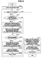
- Fig. 4 illustrates a flow chart realized by the control unit 202 of the providing apparatus 101.
- the control unit 202 realizes the flow chart by reading a program stored in the storage unit 201.
- the flow chart is realized if the providing apparatus 101 starts providing a service.
- the provision of the service is started if a user performs a predetermined operation such as power-on of the providing apparatus 101, a predetermined time period has expired, or a predetermined message is received from an external device such as the using apparatus 111 or 112, etc.
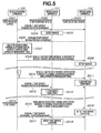
- Fig. 5 illustrates a sequence chart of the case in which the providing apparatus 101 provides a service and the using apparatuses 111 and 112 use the service.
- the providing apparatus 101 and the using apparatuses 111 and 112 have already joined the wireless LAN 131 configured by the AP 121. Further, the using apparatus 111 is set to receive a multicast message sent from the providing apparatus 101, whereas the using apparatus 112 is set not to receive a multicast message sent from the providing apparatus 101.
- the using apparatus 112 is set not to receive a multicast message sent by the TCP/IP or UDP/IP function.
- TCP is an abbreviation of "Transmission Control Protocol.”
- IP is an abbreviation of "Internet Protocol.”
- UDP is an abbreviation of "User Datagram Protocol.”
- step S501 a user operates the providing apparatus 101 to start providing a service.
- steps S502 and S503 users operate the using apparatuses 111 and 112 to start searching for a service.
- step S401 if the providing apparatus 101 starts providing the service, the time measurement unit 301 starts measuring the time.
- step S402 the stop determination unit 302 determines whether the provision of the service is stopped. Until the providing apparatus 101 stops the provision of the service (until YES in step S402), the providing apparatus 101 repeats management of the using apparatuses (steps S403 to S405) and notification of the service information (steps S406 to S409).
- step S403 the request message receiving unit 303 determines whether the request message receiving unit 303 has received a service information search message from the using apparatus 111 or 112.
- step S403 the request message receiving unit 303 has received no service information search message (NO in step S403). If the request message receiving unit 303 has received no service information search message (NO in step S403), then in step S406, the time measurement unit 301 determines whether a predetermined time period is measured. In the present embodiment, the predetermined time period is measured.
- step S407 the service notification unit 305 sends a service presence notification message by unicast addressing to the using apparatus registered in the using apparatus management table 601. If, however, no using apparatus is registered in the using apparatus management table 601, the service notification unit 305 sends no unicast service presence notification message.
- step S408 and S504 the service notification unit 305 sends no unicast service presence notification message but sends a multicast service presence notification message.
- step S409 if the service notification unit 305 sends the multicast service presence notification message, the time measurement unit 301 resets the timer and starts measuring the time again.
- Step S505 the using apparatus 111 having received the multicast service presence notification message detects that the providing apparatus 101 provides the service. On the other hand, the using apparatus 112 does not detect that the providing apparatus 101 provides the service, because the using apparatus 112 does not receive the multicast service presence notification message.
- step S506 the using apparatus 112 multicasts a service information search message at predetermined timing. If the request message receiving unit 303 receives the service information search message and determines that the request message receiving unit 303 receives the service information search message (YES in step S403), then in steps S404 and S507, the using apparatus management unit 304 registers information about the source apparatus having sent the service information search message in the using apparatus management table 601 and stores the information in the storage unit 201. In the present embodiment, the using apparatus management unit 304 registers an IP address and a source port number of the using apparatus 112 in the using apparatus management table 601 such that the IP address and the source port number are associated with each other.
- the service notification unit 305 sends a response message by unicast addressing to the using apparatus 112 in response to the received service information search message.
- the using apparatus 112 having received the service information search response message detects that the providing apparatus 101 provides the service.
- step S406 the time measurement unit 301 determines again whether the predetermined time is measured. If the predetermined time is measured (YES in step S406), then in steps S407 and S510, the service notification unit 305 sends a service presence notification message by unicast addressing to the using apparatus registered in the using apparatus management table 601.
- step S511 the using apparatus 112 having received the unicast service presence notification message detects that the providing apparatus 101 continues the provision of the service, and the using apparatus 112 clears an aging timer which is internally managed.
- aging timer refers to a timer used to determine whether the providing apparatus 101 continues providing the service.
- the service notification unit 305 sends a service presence notification message by multicast addressing.
- the using apparatus 111 having received the multicast service presence notification message also detects that the providing apparatus 101 continues the provision of the service, and the using apparatus 111 clears the aging timer which is internally managed. Thereafter, the time measurement unit 301 resets the timer and starts measuring the time again.
- the service notification unit 305 sends a service presence notification message by unicast addressing and multicast addressing in a predetermined cycle.
- step S402 The following describes the case in which the user operates the providing apparatus 101 thereafter to stop the provision of the service. If the user carries out a stop operation (YES in step S402), then in steps S410 and S515, the service notification unit 305 sends a service withdrawal notification message by unicast addressing to the using apparatus registered in the using apparatus management table 601. In step S516, the using apparatus 112 having received the unicast service withdrawal notification message detects that the providing apparatus 101 stops the provision of the service.
- the service notification unit 305 sends a service withdrawal notification message to multicast addresses designated by SSDP.
- the using apparatus 111 having received the multicast service withdrawal notification message also detects that the providing apparatus 101 stops the provision of the service. Then, in step S412, the time measurement unit 301 stops the timer.
- a using apparatus (the using apparatus 112 in the above example) that does not receive a multicast packet can also be notified of the service state of a providing apparatus. Furthermore, a using apparatus (the using apparatus 111 in the above example) that does not send a service information search message to a providing apparatus can also be notified of the service state of the providing apparatus.
- the information about the using apparatus is stored in the using apparatus management table in response to the reception of the service information search message from the using apparatus.
- the information about the using apparatus can be stored in the using apparatus management table in response to a user operation, or an IP address stored in an Address Resolution Protocol (ARP) table can be stored as the information of the using apparatus.
- ARP table is a correspondence table for use in IP communication that lists IP addresses and corresponding media access control (MAC) addresses of devices.
- DHCP dynamic host configuration protocol
- information of a using apparatus outside the broadcast domain can be stored.
- various unicast messages can be sent to a using apparatus that does not send a service information search message, whereby the using apparatus can be notified of the service state of the providing apparatus 101.
- Membership Query message refers to a message that enables a multicast message to be received by unicast addressing.
- the AP having received a Membership Query message sends various multicast messages sent by unicast addressing to an apparatus that has sent the Membership Query message.
- a multicast message sent from the providing apparatus is resent by the AP by unicast addressing to the apparatus that has sent the Membership Query message.
- the providing apparatus does not have to send the message by unicast addressing to the apparatus. Since the providing apparatus does not send a unicast message to the apparatus, the communication band being used can be prevented from increasing.
- the second embodiment will describe the case in which apparatuses each having a function both as a providing apparatus and as a using apparatus monitor the service states of one another by use of a plurality of service detection protocols.
- elements that are similar to those in the first embodiment are given the same reference numerals, and description of the elements is omitted.
- FIG. 7 illustrates the configuration of a system according to the present embodiment.
- four communication apparatuses hereinafter “providing apparatuses” 701 to 704, each of which provides and uses a service, are connected to one another via the AP 121.
- the providing apparatus 701 is compatible with both the service detection protocols SSDP and mDNS.
- the providing apparatuses 702 and 704 are compatible with SSDP but incompatible with mDNS.
- the providing apparatus 703 is compatible with mDNS but incompatible with SSDP.
- the hardware configurations of the providing apparatuses 701 to 704 are similar to that of the providing apparatus 101 according to the first embodiment, so description of the hardware configurations is omitted in the present embodiment.
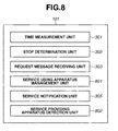
- Fig. 8 illustrates the function block diagram of the providing apparatus 701.
- the control unit 202 reads and executes a program stored in the storage unit 201 to realize the function blocks of the providing apparatus 701.
- a part or all of the function blocks of the providing apparatus 701 can be realized by hardware devices.
- the function blocks that are similar to those in the first embodiment are given the same reference numerals, and description of the function blocks is omitted in the present embodiment.
- the function blocks of the providing apparatuses 702 to 704 are also similar to those in the first embodiment, so description of the function blocks is also omitted in the present embodiment.
- a using apparatus management unit 801 registers in a using apparatus management table 1101 ( Fig. 11 ) information about an apparatus determined as a using apparatus, and stores the information in the storage unit 201.
- the using apparatus management table 1101 stores an IP address and a source port number of the using apparatus and corresponding protocol type such that the IP address, the source port number, and the corresponding protocol type are associated with one another.
- a providing apparatus detection unit 802 detects another providing apparatus based on a message received from another providing apparatus. Specifically, if the providing apparatus detection unit 802 receives a service presence notification message, the providing apparatus detection unit 802 detects the source apparatus that has sent the service presence notification message as another providing apparatus.
- Fig. 9 illustrates a flow chart realized by the control unit 202 of the providing apparatus 701.
- the control unit 202 realizes the flow chart by reading a program stored in the storage unit 201.
- the flow chart is realized when the providing apparatus 701 starts providing a service.
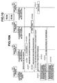
- Fig. 10 illustrates a sequence chart of the case in which the providing apparatuses 701 to 704 provide and search for a service.
- the providing apparatuses 701 to 704 have already joined the wireless LAN 131 configured by the AP 121. Further, each of the providing apparatuses 701 to 703 is set to receive a multicast message sent from another providing apparatus, whereas the providing apparatus 704 is set not to receive a multicast message sent from another providing apparatus.
- steps S1001 to S1004 users operate the providing apparatuses 701 to 704 to start providing and searching for a service.
- step S901 when the providing apparatus 701 starts providing a service, the time measurement unit 301 starts measuring the time.
- step S902 the stop determination unit 302 determines whether the provision of the service is stopped. If the provision of the service is not stopped, then in step S903, it is determined whether the request message receiving unit 303 has received a service information search message from the using apparatus 111 or 112.
- step S903 The following describes the case in which the request message receiving unit 303 has received no service information search message (NO in step S903). If the request message receiving unit 303 has received no service information search message (NO in step S903), then in step S905, the service notification unit 305 determines whether it is time to send a Notify message defined by SSDP as a service presence notification message, based on the time measured by the time measurement unit 301.
- the service notification unit 305 determines that it is time to send a Notify message. If it is time to send a Notify message (YES in step S905), then in step S906, the service notification unit 305 sends a Notify message by unicast addressing to a using apparatus registered in the using apparatus management table 1101. If, however, no using apparatus is registered in the using apparatus management table 1101, the service notification unit 305 sends no unicast Notify message.
- the service notification unit 305 sends no unicast Notify message.
- the service notification unit 305 sends a multicast Notify message.
- step S1006 the providing apparatus 702 having received the multicast Notify message detects that the providing apparatus 701 provides the service.
- the providing apparatus 703 does not receive the multicast Notify message, because the providing apparatus 703 is incompatible with SSDP.
- the providing apparatus 704 also does not receive the multicast Notify message, because the providing apparatus 704 is set not to receive a multicast message. Accordingly, at this stage, the providing apparatuses 703 and 704 do not detect that the providing apparatus 701 provides the service.
- step S908 the service notification unit 305 determines whether it is time to send an mDNS-compliant service presence notification message, based on the time measured by the time measurement unit 301.
- the service notification unit 305 determines that it is time to send an mDNS-compliant service presence notification message. If it is time to send an mDNS-compliant service presence notification message, then in steps S909 and S1007, the service notification unit 305 sends an mDNS-compliant service presence notification message by multicast addressing.
- step S1008 the providing apparatus 703 having received the mDNS-compliant service presence notification message detects that the providing apparatus 701 provides the service. On the other hand, the providing apparatus 704 does not receive the mDNS-compliant service presence notification message, because the providing apparatus 704 is incompatible with mDNS.
- the providing apparatus detection unit 802 detects another providing apparatus based on a message received from another apparatus. Specifically, if the providing apparatus detection unit 802 receives a service presence notification message, the providing apparatus detection unit 802 detects the source apparatus that has sent the service presence notification message as another providing apparatus.
- the providing apparatus detection unit 802 has received no service presence notification message from other apparatuses. Thus, the providing apparatus detection unit 802 has not detected another providing apparatus.
- step S912 the providing apparatus detection unit 802 determines whether another providing apparatus stops the provision of the service, based on the message received from another apparatus. Specifically, if the providing apparatus detection unit 802 receives a service withdrawal notification message, the providing apparatus detection unit 802 determines that the source apparatus that has sent the service withdrawal notification message stops the provision of the service. If another providing apparatus stops the provision of the service (YES in step S912), then in step S913, the using apparatus management unit 801 deletes from the using apparatus management table 1101 the information about another providing apparatus that stops the provision of the service.
- the providing apparatus detection unit 802 has received no service withdrawal notification message from other apparatuses. Thus, the providing apparatus detection unit 802 has not detected that another providing apparatus stops the provision of the service.
- step S1009 the providing apparatus 704 sends a service information search message by multicast addressing at predetermined timing.
- the request message receiving unit 303 receives the service information search message and determines that the request message receiving unit 303 receives the service information search message (YES in step S903).
- the service notification unit 305 sends a response message in response to the received service information search message.
- the service notification unit 305 sends a unicast response message in response to a SSDP service information search request, or sends a multicast response message in response to a mDNS service information search request.
- the providing apparatus 704 having received the service information search response message detects that the providing apparatus 701 provides the service.
- steps S1012, S1014, and S1016 if the providing apparatuses 702 to 704 send a service presence notification message, the providing apparatus detection unit 802 receives the service presence notification messages to detect the providing apparatuses 702 to 704 (YES in step S910).
- the using apparatus management unit 801 registers information about the detected providing apparatuses 702 to 704 in the using apparatus management table 1101 and stores the information in the storage unit 201.
- the using apparatus management unit 801 registers an IP address and a source port number of each of the providing apparatuses 702 to 704 and corresponding protocol type in the using apparatus management table 1101 such that the IP address, the source port number, and the corresponding protocol type are associated with one another.
- step S906 the service notification unit 305 sends a Notify message by unicast addressing to the using apparatuses registered in the using apparatus management table 601.
- steps S1018 and S1020 the service notification unit 305 sends a Notify message by unicast addressing to the using apparatus that is compatible with SSDP among the using apparatuses registered in the using apparatus management table 601.
- the service notification unit 305 sends no Notify message to the using apparatus that is incompatible with SSDP. This enables efficient use of the communication band.
- the providing apparatuses 702 and 704 having received the unicast Notify message detect that the providing apparatus 701 continues to provide the service, and the providing apparatuses 702 and 704 clear the aging timers which are internally managed. Then, in steps S907 and S1022, the service notification unit 305 further sends a multicast Notify message.
- the service notification unit 305 sends an mDNS-compliant service presence notification message by multicast addressing.
- step S1024 the providing apparatus 703 having received the mDNS-compliant service presence notification message detects that the providing apparatus 701 continues to provide the service, and the providing apparatus 703 clears an aging apparatus which are internally managed.
- step S914 the service notification unit 305 sends an SSDP-compliant service withdrawal notification message by unicast addressing.
- the service notification unit 305 sends a service withdrawal notification message by unicast addressing.
- the using apparatus of which the protocol type is SSDP is determined as the using apparatus that may not receive a multicast message.
- the service notification unit 305 sends a service withdrawal notification message by unicast addressing to the using apparatus of which the protocol type is SSDP.
- the service notification unit 305 further sends an SSDP-compliant service withdrawal notification message and an mNDS-compliant service withdrawal notification message by multicast addressing.
- the providing apparatuses 702 to 704 having received the service withdrawal notification messages detect that the providing apparatus 701 stops the provision of the service.
- the time measurement unit 301 stops the timer and ends the processing.
- the notification message is sent by unicast addressing only to the using apparatus that may not be able to receive a multicast packet. This enables efficient notification of the withdrawal of the service to the using apparatuses.
- Fig. 12 illustrates the configuration of a system according to the third embodiment.
- the system includes four communication apparatuses (hereinafter "providing apparatuses") 1201 to 1204 each providing and using a service.
- Each of the providing apparatuses 1201 to 1204 selects one of the plurality of wireless LAN connection methods described below to connect to the wireless network.
- the hardware configurations of the providing apparatuses 1201 to 1204 are similar to that of the providing apparatus 101, therefore description of the hardware configurations is omitted in the present embodiment.
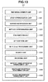
- Fig. 13 illustrates the function block diagram of the providing apparatus 1201.
- the control unit 202 reads and executes a program stored in the storage unit 201 to realize the function blocks of the providing apparatus 1201.
- a part or all of the function blocks of the providing apparatus 1201 can be realized by hardware devices.
- the function blocks that are similar to those in the first embodiment are given the same reference numerals, and description of the function blocks is omitted in the present embodiment.
- the function blocks of the providing apparatuses 1202 to 1204 are also similar to those in the first embodiment, therefore description of the function blocks is omitted in the present embodiment.
- a method determination unit 1301 determines the wireless LAN connection method based on the information stored in advance in the storage unit 201.
- a station (STA) function unit 1302 provides various functions that enable the providing apparatus 1201 to operate as an apparatus controlled by the AP 121.
- An AP function unit 1303 provides various functions that enable the providing apparatus 1201 to operate as an apparatus that controls the wireless network.
- a Wi-Fi Direct processing unit 1304 establishes a wireless LAN connection with other wireless apparatuses by use of a procedure according to the Wi-Fi Direct (trademark) standards defined by the Wi-Fi Alliance.
- a search unit 1305 sends an M-SEARCH message defined by SSDP by multicast addressing.
- a receiving unit 1306 executes processing to receive a message sent from other providing apparatuses.
- a using apparatus management unit 1307 manages a unicast destination apparatus and stores the unicast destination apparatus in the storage unit 201.
- a multicast reception determination unit 1308 determines whether another apparatus is an apparatus that can receive a multicast.
- a device information management unit 1309 acquires device information about an apparatus having sent a Notify message, and stores the device information in the storage unit 201 to manage the device information.
- Fig. 14 illustrates a flow chart realized by the control unit 202 of the providing apparatus 1201.
- the control unit 202 realizes the flow chart by reading a program stored in the storage unit 201.
- the flow chart is realized if the providing apparatus 1201 starts providing a service.
- step S1401 if the providing apparatus 1201 starts providing a service, the method determination unit 1301 determines the wireless LAN connection method based on the information stored in advance in the storage unit 201.
- the wireless LAN connection method there are first and second methods.
- the wireless LAN connection is established in the STA mode in which the providing apparatus 1201 operates as an apparatus controlled by the AP 121.
- the wireless LAN connection is established in the AP mode in which the providing apparatus 1201 controls the wireless network.
- the wireless LAN connection is established with another wireless apparatus by use of the procedure according to the Wi-Fi Direct (trademark) standards defined by the Wi-Fi Alliance.
- Wi-Fi Direct trademark
- one apparatus and another apparatus determine which one of them operates in the STA mode or in the AP mode, and then each of the apparatuses communicates with each other according to the determined role.
- step S1402 if the method (first method) in which the providing apparatus 1201 operates in the STA mode is selected, the STA function unit 1302 connects to the AP 121.
- step S1403 if the method (second method) in which the providing apparatus 1201 operates in the AP mode is selected, the AP function unit 1303 starts operating as an AP and configures a wireless network.
- step S1404 if the method (third method) in which the providing apparatus 1201 performs Wi-Fi Direct is selected, the Wi-Fi Direct processing unit 1304 performs connection processing according to the Wi-Fi Direct standard.
- the providing apparatus 1201 operates in the STA mode or AP mode depending on the result of the connection processing.
- the providing apparatus 1201 starts providing the service and repeats steps S1406 to S1422 until the providing apparatus 1201 stops the provision of the service (until YES in step S1405).
- the providing apparatus 1201 stops the provision of the service when, for example, the providing apparatus 1201 leaves the wireless network in response to a user command or when the providing apparatus 1201 leaves the wireless network in view of a remaining battery level of the providing apparatus 1201.
- step S1406 if the providing apparatus 1201 does not stop the provision of the service, the time measurement unit 301 determines whether it is the timing to send a Notify message. If it is the timing to send a Notify message (YES in step S1406), then in step S1407, the service notification unit 305 sends a Notify message by multicast addressing. Further, in step S1408, the service notification unit 305 sends a Notify message by unicast addressing to a unicast destination apparatus described below.
- step S1409 the time measurement unit 301 determines whether it is the timing to send an M-SEARCH message. If it is the timing to send an M-SEARCH message (YES in step S1409), then in step S1410, the search unit 1305 sends an M-SEARCH message by multicast addressing.
- step S1411 the receiving unit 1306 performs processing to receive the message sent by other providing apparatus.
- step S1412 if the received message is the Notify message, the device information management unit 1309 determines whether the apparatus that has sent the Notify message is already managed by the device information management unit 1309.
- step S1413 the device information management unit 1309 acquires device information about the apparatus that has sent the Notify message, and the device information management unit 1309 stores the device information in the storage unit 201.
- device information refers to a Device Description defined by the Universal Plug and Play (UPnP) specification.
- step S1414 the multicast reception determination unit 1308 determines whether the apparatus is an apparatus that can receive a multicast, based on the acquired device information. If the multicast reception determination unit 1308 determines that the apparatus cannot receive a multicast or that it is not certain whether the providing apparatus can receive a multicast (NO in step S1414), then in step S1415, the using apparatus management unit 1307 stores the apparatus as a unicast destination apparatus.
- step S1416 if the received message is a response message, the device information management unit 1309 determines whether the apparatus that has sent the Notify message is already managed by the device information management unit 1309. If the apparatus that has sent the Notify message is not registered (NO in step S1416), then in step S1417, the device information management unit 1309 acquires device information about the apparatus that has sent the Notify message, and the device information management unit 1309 stores the device information in the storage unit 201.
- step S1418 the using apparatus management unit 1307 determines whether the apparatus that has sent the response message is already registered as a unicast destination apparatus. If the apparatus that has sent the response message is already registered as a unicast destination apparatus (YES in step S1418), then in step S1419, the using apparatus management unit 1307 deletes the information about the apparatus. Since an apparatus that sends a response message is considered to have been able to receive an information search message sent by multicast addressing, the terminal can be eliminated from the unicast destination terminals.
- step S1420 the service notification unit 305 sends a response message by unicast addressing to the source apparatus that has sent the M-SEARCH message.
- step S1421 the using apparatus management unit 1307 determines whether the apparatus that has sent the byebye message is already registered as a unicast destination apparatus. If the apparatus is already registered as a unicast destination apparatus (YES in step S1421), then in step S1422, the using apparatus management unit 1307 deletes the information about the apparatus. Further, in step S1423, the device information management unit 1309 deletes the device information about the apparatus.
- step S1424 if the providing apparatus 1201 is to stop the provision of the service, the method determination unit 1301 determines whether the providing apparatus 1201 is connected in the STA mode.
- step S1425 the service notification unit 305 sends a byebye message by unicast addressing to the apparatus registered as a unicast destination apparatus. Then, in step S1426, the service notification unit 305 sends a byebye message by multicast addressing.
- step S1427 the providing apparatus 701 disconnects from the wireless connection. If the providing apparatus 701 operates in the AP mode, the AP function is stopped at this point. Thus, the wireless LAN network communicating with other providing apparatuses is terminated.
- the unicast notification message is sent only to the using apparatus that may not be able to receive appropriately a multicast. This enables efficient notification of the termination of the service to the using apparatuses.
- a message can be sent to a detected providing apparatus to inquire about whether the detected providing apparatus receives a multicast packet. Then it can be determined based on a response message whether the detected providing apparatus receives a multicast packet. Alternatively, whether the detected providing apparatus receives a multicast packet can be determined based on the type of the detected providing apparatus, the version of software, etc.
- the method by which a providing apparatus determines whether a using apparatus can receive a multicast packet is not limited to the method described above. For example, whether a using apparatus can receive a multicast packet can be determined based on the MAC address of the using apparatus, device information about the using apparatus, version of an OS or application software, user's presetting, etc. Alternatively, an identifier of the using apparatus and the determination result can be stored in a nonvolatile memory, and then whether a using apparatus can receive a multicast packet can be determined using the stored information.
- a unicast message can be sent to a discovered service providing apparatus to inquire whether the discovered service providing apparatus receives a multicast packet. Then, whether the discovered service providing apparatus receives a multicast packet can be determined based on a response message. For example, in the device information (Device Description) acquisition processing described above, information indicating whether the apparatus receives a multicast packet can be included in the device information of the apparatus. Whether the discovered service providing apparatus receives a multicast packet can be determined based on the device information.
- the method of acquiring information about the using apparatus does not have to use UPnP or mDNS as described above, and the information can be acquired using a unique communication unit.
- information about the type of the using apparatus can be acquired by a near-field wireless communication unit that is different from the wireless LAN, and then whether the using apparatus can receive a multicast packet can be determined using the acquired information.
- a communication apparatus can notify other communication apparatuses that do not receive a multicast signal of information on a function provided by the communication apparatus when the communication apparatus sends a multicast signal to notify the information on the function provided by the communication apparatus.
- Embodiments of the present invention can also be realized by a computer of a system or apparatus that reads out and executes computer executable instructions recorded on a storage medium (e.g., non-transitory computer-readable storage medium) to perform the functions of one or more of the above-described embodiment(s) of the present invention, and by a method performed by the computer of the system or apparatus by, for example, reading out and executing the computer executable instructions from the storage medium to perform the functions of one or more of the above-described embodiment(s).
- the computer may comprise one or more of a central processing unit (CPU), micro processing unit (MPU), or other circuitry, and may include a network of separate computers or separate computer processors.
- the computer executable instructions may be provided to the computer, for example, from a network or the storage medium.
- the storage medium may include, for example, one or more of a hard disk, a random-access memory (RAM), a read only memory (ROM), a storage of distributed computing systems, an optical disk (such as a compact disc (CD), digital versatile disc (DVD), or Blu-ray Disc (BD) TM ), a flash memory device, a memory card, and the like.
Landscapes
- Engineering & Computer Science (AREA)
- Computer Networks & Wireless Communication (AREA)
- Signal Processing (AREA)
- Computer Security & Cryptography (AREA)
- Multimedia (AREA)
- Small-Scale Networks (AREA)
- Mobile Radio Communication Systems (AREA)
- Computer And Data Communications (AREA)
- Data Exchanges In Wide-Area Networks (AREA)
Abstract
Description
- The present invention relates to a communication apparatus configured to send information about a function provided by the communication apparatus.
- There are communication protocols (hereinafter "service detection protocols") for a communication apparatus to search for a function provided by other communication apparatuses and notify other communication apparatuses of information about a function provided by the communication apparatus via a network. According to the service detection protocols, a communication apparatus sends information about a function provided by the communication apparatus in a multicast signal, thereby notifying an unspecified number of service using apparatuses present in the network about the function provided by the providing apparatus and a change (termination, etc.) in the function.
- Meanwhile, there is a communication apparatus that does not receive the multicast signal. Japanese Patent Application Laid-Open No.
2006-203344 2006-203344 - However, when the function using apparatus inquires of the providing apparatus about the function provided by the providing apparatus, if the function provided by the providing apparatus has been changed, there is a time lag from when the change has been made until the function using apparatus detects the change in the function.
- In view of immediacy, the function using apparatus desirably detects the change when notified from the function providing apparatus about the change in the function.
- The present invention is directed to enabling a communication apparatus to notify other communication apparatuses that do not receive a multicast signal of information about a function provided by the communication apparatus when the communication apparatus sends a multicast signal to notify the information about the function provided by the communication apparatus.
- The present invention in its first aspect provides a communication apparatus as specified in
claims 1 to 7. - Further features of the present invention will become apparent from the following description of exemplary embodiments with reference to the attached drawings.
-
-
Fig. 1 illustrates the configuration of a system according to a first exemplary embodiment. -
Fig. 2 illustrates the hardware configuration of a providing apparatus. -
Fig. 3 is a function block diagram realized by the providing apparatus. -
Fig. 4 is a flow chart realized by the providing apparatus. -
Fig. 5 is a sequence chart according to the first exemplary embodiment. -
Fig. 6 illustrates a function using apparatus management table according to the first exemplary embodiment. -
Fig. 7 illustrates the configuration of a system according to a second exemplary embodiment. -
Fig. 8 is a function block diagram realized by a providing apparatus. -
Fig. 9 is a flow chart realized by the function providing apparatus. -
Fig. 10 is a sequence chart according to the second exemplary embodiment. -
Fig. 11 illustrates a function using apparatus management table according to the second exemplary embodiment. -
Fig. 12 illustrates the configuration of a system according to a third exemplary embodiment. -
Fig. 13 is a function block diagram realized by a function providing apparatus. -
Fig. 14 is a flow chart realized by thefunction providing apparatus 101. - Various embodiments, features, and aspects of the invention will be described in detail below with reference to the drawings.
-
Fig. 1 illustrates the configuration of a system according to the first embodiment. In the system, one communication apparatus (hereinafter "providing apparatus") 101, which provides a service, and two other communication apparatuses (hereinafter "using apparatuses") 111 and 112, which use the service provided by the providingapparatus 101, are connected together via an access point (hereinafter "AP") 121. The AP 121 manages a wireless local area network (LAN) 131 compliant with the IEEE 802.11 family. As used herein, the term "service" refers to a function that the providing apparatus provides to the using apparatuses. Examples include an image publication service for providing image data stored in astorage unit 201 to the using apparatuses. - Each of the apparatuses communicates via the
wireless LAN 131 compliant with the IEEE 802.11 family. In place of the IEEE 802.11 family, the apparatuses can communicate via a wired LAN such as Ethernet (registered trademark) or a wireless network compliant with any other communication standard such as Bluetooth (registered trademark) and long-term evolution (LTE). "IEEE" is an abbreviation of the Institute of Electrical and Electronics Engineers. - The using
apparatus 112 is set not to receive a multicast packet sent from the providingapparatus 101. As used herein, the term "multicast packet" refers to a packet that is sent to a plurality of destination devices. Further, each apparatus is set to receive a unicast packet. As used herein, the term "unicast packet" refers to a packet that is sent to a single destination device. - While the present embodiment assumes the providing
apparatus 101 to be a digital camera, the providingapparatus 101 is not limited to the digital camera and can be any other device such as a printer, storage medium, personal computer, and mobile phone. While the present embodiment assumes the usingapparatuses apparatuses -
Fig. 2 illustrates the hardware configuration of the providingapparatus 101. Since the hardware configurations of the usingapparatuses apparatus 101, description of the hardware configurations of the usingapparatuses - The
storage unit 201 includes a read-only memory (ROM) and random-access memory (RAM) and stores programs for executing various operations that will be described below and various types of data such as wireless communication network information, data transmission and reception information, and communication apparatus information. In place of a memory such as ROM and RAM, other storage media can be used as thestorage unit 201 such as a flexible disk, hard disk, optical disk, magnetooptical disk, compact disk (CD) ROM, CD recordable (CD-R), magnetic tape, nonvolatile memory card, and DVD. - A
control unit 202 includes a central processing unit (CPU) or micro processing unit (MPU) and is configured to execute a program stored in thestorage unit 201 to control the entire providingapparatus 101. Thecontrol unit 202 can control the entire providingapparatus 101 by cooperating with an operating system (OS) executed by thecontrol unit 202. - A user interface unit (hereinafter "UI") 203 outputs various types of information and receives various user operations. The output includes at least one of a display on a screen, audio output from a speaker, and vibration output. A
timer 204 measures a predetermined time period by counting down, counting up, or measuring the time. A communication interface unit (hereinafter "communication IF") 205 performs communication compliant with the IEEE 802.11 family by use of anantenna 206. -
Fig. 3 illustrates the function block diagram of the providingapparatus 101. According to the present embodiment, thecontrol unit 202 reads and executes a program stored in thestorage unit 201 to realize the function blocks of the providingapparatus 101. A part or all of the function blocks of the providingapparatus 101 can be realized by hardware devices. - To realize a function block by the hardware devices, for example, a predetermined compiler is used to automatically generate a dedicated circuit on a field programmable gate array (FPGA) from a program for realizing the function block, and the dedicated circuit can be used as hardware having the function of the function block. A gate array circuit can be formed similar to the FPGA to realize the function block by hardware devices.
- A
time measurement unit 301 measures a predetermined time period by use of thetimer 204. Astop determination unit 302 determines whether the provision of service is stopped. Specifically, if a user performs a predetermined operation via theUI 203 such as application of power of the providingapparatus 101, thestop determination unit 302 determines that the provision of service is to be stopped. The stop determination is not limited to the above example. Thestop determination unit 302 can determine that the provision of service is stopped if a predetermined time period has expired or if a predetermined message is received from another communication apparatus. - A request
message receiving unit 303 receives from the usingapparatus apparatus 101. The requestmessage receiving unit 303 also determines whether a service information search message has been received. - According to the present embodiment, the service information search message is an M-SEARCH message defined by the Simple Service Discovery Protocol (SSDP) and a search packet for searching for service information provided by another providing apparatus. The SSDP is a communication protocol (hereinafter "service detection protocol") for searching for a service provided by another communication apparatus or notifying another communication apparatus of a service it provides. In place of or in addition to SSDP, a multicast domain name system (mDNS) protocol can be used.
- A using
apparatus management unit 304 determines a source apparatus that sends a service information search message as a using apparatus. Further, the usingapparatus management unit 304 registers in a using apparatus management table 601 (Fig. 6 ) information about the apparatus determined as a using apparatus and stores the information in thestorage unit 201. The using apparatus management table 601 stores an Internet Protocol (IP) address and a source port number of the source apparatus of the service information search message such that the IP address and the source port number are associated with each other. - A
service notification unit 305 sends a response signal (hereinafter "response message") via the communication IF 205 in response to the service information search message received by the requestmessage receiving unit 303. The response message contains information about the service provided by the providingapparatus 101. According to the present embodiment, the response message is a Response message defined by SSDP. - The
service notification unit 305 also sends a service presence notification message by unicast addressing to the using apparatus registered in the using apparatus management table 601. The service presence notification message contains the information about the service provided by the providingapparatus 101. According to the present embodiment, the service presence notification message is a Notify message defined by SSDP. Theservice notification unit 305 also sends (multicasts) the service presence notification message to multicast addresses designated by SSDP. - The
service notification unit 305 also sends a service withdrawal notification message by unicast addressing to the using apparatus registered in the using apparatus management table 601. The service withdrawal notification message notifies the using apparatus that the providingapparatus 101 stops providing the service. The service withdrawal notification contains information about the function of the service that the providingapparatus 101 stops providing. Accordingly, if the providingapparatus 101 leaves the network, the service withdrawal notification contains information about the function provided by the providingapparatus 101. According to the present embodiment, the service withdrawal notification message is a byebye message defined by SSDP. Further, theservice notification unit 305 also sends (multicasts) the service withdrawal notification message to multicast addresses designated by SSDP. - The
service notification unit 305 can be configured to send each of the above messages continuously for a plurality of times. -
Fig. 4 illustrates a flow chart realized by thecontrol unit 202 of the providingapparatus 101. Thecontrol unit 202 realizes the flow chart by reading a program stored in thestorage unit 201. The flow chart is realized if the providingapparatus 101 starts providing a service. The provision of the service is started if a user performs a predetermined operation such as power-on of the providingapparatus 101, a predetermined time period has expired, or a predetermined message is received from an external device such as the usingapparatus -
Fig. 5 illustrates a sequence chart of the case in which the providingapparatus 101 provides a service and the usingapparatuses - In the present embodiment, the providing
apparatus 101 and the usingapparatuses wireless LAN 131 configured by theAP 121. Further, the usingapparatus 111 is set to receive a multicast message sent from the providingapparatus 101, whereas the usingapparatus 112 is set not to receive a multicast message sent from the providingapparatus 101. - In the present embodiment, the using
apparatus 112 is set not to receive a multicast message sent by the TCP/IP or UDP/IP function. "TCP" is an abbreviation of "Transmission Control Protocol." "IP" is an abbreviation of "Internet Protocol." "UDP" is an abbreviation of "User Datagram Protocol." - In step S501, a user operates the providing
apparatus 101 to start providing a service. In steps S502 and S503, users operate the usingapparatuses - In step S401, if the providing
apparatus 101 starts providing the service, thetime measurement unit 301 starts measuring the time. In step S402, thestop determination unit 302 determines whether the provision of the service is stopped. Until the providingapparatus 101 stops the provision of the service (until YES in step S402), the providingapparatus 101 repeats management of the using apparatuses (steps S403 to S405) and notification of the service information (steps S406 to S409). - If the provision of the service is not stopped (NO in step S402), then in step S403, the request
message receiving unit 303 determines whether the requestmessage receiving unit 303 has received a service information search message from the usingapparatus - The following describes the case in which the request
message receiving unit 303 has received no service information search message (NO in step S403). If the requestmessage receiving unit 303 has received no service information search message (NO in step S403), then in step S406, thetime measurement unit 301 determines whether a predetermined time period is measured. In the present embodiment, the predetermined time period is measured. - If the predetermined time is measured (YES in step S406), then in step S407, the
service notification unit 305 sends a service presence notification message by unicast addressing to the using apparatus registered in the using apparatus management table 601. If, however, no using apparatus is registered in the using apparatus management table 601, theservice notification unit 305 sends no unicast service presence notification message. - At this stage, no using apparatus is registered in the using apparatus management table 601. Accordingly, in steps S408 and S504, the
service notification unit 305 sends no unicast service presence notification message but sends a multicast service presence notification message. In step S409, if theservice notification unit 305 sends the multicast service presence notification message, thetime measurement unit 301 resets the timer and starts measuring the time again. - In Step S505, the using
apparatus 111 having received the multicast service presence notification message detects that the providingapparatus 101 provides the service. On the other hand, the usingapparatus 112 does not detect that the providingapparatus 101 provides the service, because the usingapparatus 112 does not receive the multicast service presence notification message. - In step S506, the using
apparatus 112 multicasts a service information search message at predetermined timing. If the requestmessage receiving unit 303 receives the service information search message and determines that the requestmessage receiving unit 303 receives the service information search message (YES in step S403), then in steps S404 and S507, the usingapparatus management unit 304 registers information about the source apparatus having sent the service information search message in the using apparatus management table 601 and stores the information in thestorage unit 201. In the present embodiment, the usingapparatus management unit 304 registers an IP address and a source port number of the usingapparatus 112 in the using apparatus management table 601 such that the IP address and the source port number are associated with each other. - In steps S405 and S508, the
service notification unit 305 sends a response message by unicast addressing to the usingapparatus 112 in response to the received service information search message. In step S509, the usingapparatus 112 having received the service information search response message detects that the providingapparatus 101 provides the service. - In step S406, the
time measurement unit 301 determines again whether the predetermined time is measured. If the predetermined time is measured (YES in step S406), then in steps S407 and S510, theservice notification unit 305 sends a service presence notification message by unicast addressing to the using apparatus registered in the using apparatus management table 601. - In step S511, the using
apparatus 112 having received the unicast service presence notification message detects that the providingapparatus 101 continues the provision of the service, and the usingapparatus 112 clears an aging timer which is internally managed. As used herein, the term "aging timer" refers to a timer used to determine whether the providingapparatus 101 continues providing the service. - In steps S408 and S512, the
service notification unit 305 sends a service presence notification message by multicast addressing. In step S513, the usingapparatus 111 having received the multicast service presence notification message also detects that the providingapparatus 101 continues the provision of the service, and the usingapparatus 111 clears the aging timer which is internally managed. Thereafter, thetime measurement unit 301 resets the timer and starts measuring the time again. As the foregoing describes, theservice notification unit 305 sends a service presence notification message by unicast addressing and multicast addressing in a predetermined cycle. - The following describes the case in which the user operates the providing
apparatus 101 thereafter to stop the provision of the service (YES in step S402, step S514). If the user carries out a stop operation (YES in step S402), then in steps S410 and S515, theservice notification unit 305 sends a service withdrawal notification message by unicast addressing to the using apparatus registered in the using apparatus management table 601. In step S516, the usingapparatus 112 having received the unicast service withdrawal notification message detects that the providingapparatus 101 stops the provision of the service. - In steps S411 and S517, the
service notification unit 305 sends a service withdrawal notification message to multicast addresses designated by SSDP. In step S518, the usingapparatus 111 having received the multicast service withdrawal notification message also detects that the providingapparatus 101 stops the provision of the service. Then, in step S412, thetime measurement unit 301 stops the timer. - According to the present embodiment, a using apparatus (the using
apparatus 112 in the above example) that does not receive a multicast packet can also be notified of the service state of a providing apparatus. Furthermore, a using apparatus (the usingapparatus 111 in the above example) that does not send a service information search message to a providing apparatus can also be notified of the service state of the providing apparatus. - In the foregoing embodiment, the information about the using apparatus is stored in the using apparatus management table in response to the reception of the service information search message from the using apparatus. However, an embodiment is not limited thereto. The information about the using apparatus can be stored in the using apparatus management table in response to a user operation, or an IP address stored in an Address Resolution Protocol (ARP) table can be stored as the information of the using apparatus. The ARP table is a correspondence table for use in IP communication that lists IP addresses and corresponding media access control (MAC) addresses of devices.
- Further, if the providing apparatus has a dynamic host configuration protocol (DHCP) server function, an address assigned to the DHCP server can be stored as the information of the using apparatus.
- Further, information of a using apparatus outside the broadcast domain can be stored. By this way, various unicast messages can be sent to a using apparatus that does not send a service information search message, whereby the using apparatus can be notified of the service state of the providing
apparatus 101. - Further, only the information about an apparatus that does not send a Membership Query message defined by the Internet Group Management Protocol (IGMP) can be stored in the using apparatus management table. The term "Membership Query message" refers to a message that enables a multicast message to be received by unicast addressing. Specifically, the AP having received a Membership Query message sends various multicast messages sent by unicast addressing to an apparatus that has sent the Membership Query message.
- In other words, a multicast message sent from the providing apparatus is resent by the AP by unicast addressing to the apparatus that has sent the Membership Query message. Thus, the providing apparatus does not have to send the message by unicast addressing to the apparatus. Since the providing apparatus does not send a unicast message to the apparatus, the communication band being used can be prevented from increasing.
- The second embodiment will describe the case in which apparatuses each having a function both as a providing apparatus and as a using apparatus monitor the service states of one another by use of a plurality of service detection protocols. In the following description, elements that are similar to those in the first embodiment are given the same reference numerals, and description of the elements is omitted.
-
Fig. 7 illustrates the configuration of a system according to the present embodiment. In the system, four communication apparatuses (hereinafter "providing apparatuses") 701 to 704, each of which provides and uses a service, are connected to one another via theAP 121. - The providing
apparatus 701 is compatible with both the service detection protocols SSDP and mDNS. The providingapparatuses apparatus 703 is compatible with mDNS but incompatible with SSDP. - The hardware configurations of the providing
apparatuses 701 to 704 are similar to that of the providingapparatus 101 according to the first embodiment, so description of the hardware configurations is omitted in the present embodiment. -
Fig. 8 illustrates the function block diagram of the providingapparatus 701. According to the present embodiment, thecontrol unit 202 reads and executes a program stored in thestorage unit 201 to realize the function blocks of the providingapparatus 701. A part or all of the function blocks of the providingapparatus 701 can be realized by hardware devices. The function blocks that are similar to those in the first embodiment are given the same reference numerals, and description of the function blocks is omitted in the present embodiment. Further, the function blocks of the providingapparatuses 702 to 704 are also similar to those in the first embodiment, so description of the function blocks is also omitted in the present embodiment. - A using
apparatus management unit 801 registers in a using apparatus management table 1101 (Fig. 11 ) information about an apparatus determined as a using apparatus, and stores the information in thestorage unit 201. The using apparatus management table 1101 stores an IP address and a source port number of the using apparatus and corresponding protocol type such that the IP address, the source port number, and the corresponding protocol type are associated with one another. - A providing
apparatus detection unit 802 detects another providing apparatus based on a message received from another providing apparatus. Specifically, if the providingapparatus detection unit 802 receives a service presence notification message, the providingapparatus detection unit 802 detects the source apparatus that has sent the service presence notification message as another providing apparatus. -
Fig. 9 illustrates a flow chart realized by thecontrol unit 202 of the providingapparatus 701. Thecontrol unit 202 realizes the flow chart by reading a program stored in thestorage unit 201. The flow chart is realized when the providingapparatus 701 starts providing a service.Fig. 10 illustrates a sequence chart of the case in which the providingapparatuses 701 to 704 provide and search for a service. - In the present embodiment, the providing
apparatuses 701 to 704 have already joined thewireless LAN 131 configured by theAP 121. Further, each of the providingapparatuses 701 to 703 is set to receive a multicast message sent from another providing apparatus, whereas the providingapparatus 704 is set not to receive a multicast message sent from another providing apparatus. - In steps S1001 to S1004, users operate the providing
apparatuses 701 to 704 to start providing and searching for a service. In step S901, when the providingapparatus 701 starts providing a service, thetime measurement unit 301 starts measuring the time. - In step S902, the
stop determination unit 302 determines whether the provision of the service is stopped. If the provision of the service is not stopped, then in step S903, it is determined whether the requestmessage receiving unit 303 has received a service information search message from the usingapparatus - The following describes the case in which the request
message receiving unit 303 has received no service information search message (NO in step S903). If the requestmessage receiving unit 303 has received no service information search message (NO in step S903), then in step S905, theservice notification unit 305 determines whether it is time to send a Notify message defined by SSDP as a service presence notification message, based on the time measured by thetime measurement unit 301. - In the present embodiment, the
service notification unit 305 determines that it is time to send a Notify message. If it is time to send a Notify message (YES in step S905), then in step S906, theservice notification unit 305 sends a Notify message by unicast addressing to a using apparatus registered in the using apparatus management table 1101. If, however, no using apparatus is registered in the using apparatus management table 1101, theservice notification unit 305 sends no unicast Notify message. - At this stage, no using apparatus is registered in the using apparatus management table 1101. Thus, the
service notification unit 305 sends no unicast Notify message. In steps S907 and S1005, theservice notification unit 305 sends a multicast Notify message. - In step S1006, the providing
apparatus 702 having received the multicast Notify message detects that the providingapparatus 701 provides the service. On the other hand, the providingapparatus 703 does not receive the multicast Notify message, because the providingapparatus 703 is incompatible with SSDP. Further, the providingapparatus 704 also does not receive the multicast Notify message, because the providingapparatus 704 is set not to receive a multicast message. Accordingly, at this stage, the providingapparatuses apparatus 701 provides the service. - Then, in step S908, the
service notification unit 305 determines whether it is time to send an mDNS-compliant service presence notification message, based on the time measured by thetime measurement unit 301. - In the present embodiment, the
service notification unit 305 determines that it is time to send an mDNS-compliant service presence notification message. If it is time to send an mDNS-compliant service presence notification message, then in steps S909 and S1007, theservice notification unit 305 sends an mDNS-compliant service presence notification message by multicast addressing. - In step S1008, the providing
apparatus 703 having received the mDNS-compliant service presence notification message detects that the providingapparatus 701 provides the service. On the other hand, the providingapparatus 704 does not receive the mDNS-compliant service presence notification message, because the providingapparatus 704 is incompatible with mDNS. - Then, in step S910, the providing
apparatus detection unit 802 detects another providing apparatus based on a message received from another apparatus. Specifically, if the providingapparatus detection unit 802 receives a service presence notification message, the providingapparatus detection unit 802 detects the source apparatus that has sent the service presence notification message as another providing apparatus. - At this stage, the providing
apparatus detection unit 802 has received no service presence notification message from other apparatuses. Thus, the providingapparatus detection unit 802 has not detected another providing apparatus. - Then, in step S912, the providing
apparatus detection unit 802 determines whether another providing apparatus stops the provision of the service, based on the message received from another apparatus. Specifically, if the providingapparatus detection unit 802 receives a service withdrawal notification message, the providingapparatus detection unit 802 determines that the source apparatus that has sent the service withdrawal notification message stops the provision of the service. If another providing apparatus stops the provision of the service (YES in step S912), then in step S913, the usingapparatus management unit 801 deletes from the using apparatus management table 1101 the information about another providing apparatus that stops the provision of the service. - At this stage, the providing
apparatus detection unit 802 has received no service withdrawal notification message from other apparatuses. Thus, the providingapparatus detection unit 802 has not detected that another providing apparatus stops the provision of the service. - Then, in step S1009, the providing
apparatus 704 sends a service information search message by multicast addressing at predetermined timing. The requestmessage receiving unit 303 receives the service information search message and determines that the requestmessage receiving unit 303 receives the service information search message (YES in step S903). Then, theservice notification unit 305 sends a response message in response to the received service information search message. - In steps S904 and S1010, the
service notification unit 305 sends a unicast response message in response to a SSDP service information search request, or sends a multicast response message in response to a mDNS service information search request. In step S1011, the providingapparatus 704 having received the service information search response message detects that the providingapparatus 701 provides the service. - In steps S1012, S1014, and S1016, if the providing
apparatuses 702 to 704 send a service presence notification message, the providingapparatus detection unit 802 receives the service presence notification messages to detect the providingapparatuses 702 to 704 (YES in step S910). - In steps S911, S1013, S1015, and S1017, the using
apparatus management unit 801 registers information about the detected providingapparatuses 702 to 704 in the using apparatus management table 1101 and stores the information in thestorage unit 201. The usingapparatus management unit 801 registers an IP address and a source port number of each of the providingapparatuses 702 to 704 and corresponding protocol type in the using apparatus management table 1101 such that the IP address, the source port number, and the corresponding protocol type are associated with one another. - Thereafter, if it is time to send a Notify message (YES in step S905), then in step S906, the
service notification unit 305 sends a Notify message by unicast addressing to the using apparatuses registered in the using apparatus management table 601. In steps S1018 and S1020, theservice notification unit 305 sends a Notify message by unicast addressing to the using apparatus that is compatible with SSDP among the using apparatuses registered in the using apparatus management table 601. On the other hand, theservice notification unit 305 sends no Notify message to the using apparatus that is incompatible with SSDP. This enables efficient use of the communication band. - In steps S1019 and S1021, the providing
apparatuses apparatus 701 continues to provide the service, and the providingapparatuses service notification unit 305 further sends a multicast Notify message. - If it is time to send an mDNS-compliant service presence notification message (YES in step S908), then in steps S909 and S1023, the
service notification unit 305 sends an mDNS-compliant service presence notification message by multicast addressing. - In step S1024, the providing
apparatus 703 having received the mDNS-compliant service presence notification message detects that the providingapparatus 701 continues to provide the service, and the providingapparatus 703 clears an aging apparatus which are internally managed. - Thereafter, if the user operates the providing
apparatus 701 to stop the provision of the service (YES in step S902, step S1025), then in step S914, theservice notification unit 305 sends an SSDP-compliant service withdrawal notification message by unicast addressing. To a using apparatus that may not receive a multicast message, theservice notification unit 305 sends a service withdrawal notification message by unicast addressing. - In the present embodiment, among the using apparatuses registered in the using apparatus management table 1101, the using apparatus of which the protocol type is SSDP is determined as the using apparatus that may not receive a multicast message. Thus, in steps S1026 and S1028, the
service notification unit 305 sends a service withdrawal notification message by unicast addressing to the using apparatus of which the protocol type is SSDP. - In steps S915, S916, S1030, and S1031, the
service notification unit 305 further sends an SSDP-compliant service withdrawal notification message and an mNDS-compliant service withdrawal notification message by multicast addressing. In steps S1027, S1029, and S1032, the providingapparatuses 702 to 704 having received the service withdrawal notification messages detect that the providingapparatus 701 stops the provision of the service. Then, in step S917, thetime measurement unit 301 stops the timer and ends the processing. - According to the present embodiment, the notification message is sent by unicast addressing only to the using apparatus that may not be able to receive a multicast packet. This enables efficient notification of the withdrawal of the service to the using apparatuses.
-
Fig. 12 illustrates the configuration of a system according to the third embodiment. The system includes four communication apparatuses (hereinafter "providing apparatuses") 1201 to 1204 each providing and using a service. Each of the providingapparatuses 1201 to 1204 selects one of the plurality of wireless LAN connection methods described below to connect to the wireless network. The hardware configurations of the providingapparatuses 1201 to 1204 are similar to that of the providingapparatus 101, therefore description of the hardware configurations is omitted in the present embodiment. -
Fig. 13 illustrates the function block diagram of the providingapparatus 1201. According to the present embodiment, thecontrol unit 202 reads and executes a program stored in thestorage unit 201 to realize the function blocks of the providingapparatus 1201. A part or all of the function blocks of the providingapparatus 1201 can be realized by hardware devices. The function blocks that are similar to those in the first embodiment are given the same reference numerals, and description of the function blocks is omitted in the present embodiment. The function blocks of the providingapparatuses 1202 to 1204 are also similar to those in the first embodiment, therefore description of the function blocks is omitted in the present embodiment. - A
method determination unit 1301 determines the wireless LAN connection method based on the information stored in advance in thestorage unit 201. A station (STA)function unit 1302 provides various functions that enable the providingapparatus 1201 to operate as an apparatus controlled by theAP 121. AnAP function unit 1303 provides various functions that enable the providingapparatus 1201 to operate as an apparatus that controls the wireless network. A Wi-FiDirect processing unit 1304 establishes a wireless LAN connection with other wireless apparatuses by use of a procedure according to the Wi-Fi Direct (trademark) standards defined by the Wi-Fi Alliance. - A
search unit 1305 sends an M-SEARCH message defined by SSDP by multicast addressing. A receivingunit 1306 executes processing to receive a message sent from other providing apparatuses. A usingapparatus management unit 1307 manages a unicast destination apparatus and stores the unicast destination apparatus in thestorage unit 201. A multicastreception determination unit 1308 determines whether another apparatus is an apparatus that can receive a multicast. A deviceinformation management unit 1309 acquires device information about an apparatus having sent a Notify message, and stores the device information in thestorage unit 201 to manage the device information. -
Fig. 14 illustrates a flow chart realized by thecontrol unit 202 of the providingapparatus 1201. Thecontrol unit 202 realizes the flow chart by reading a program stored in thestorage unit 201. The flow chart is realized if the providingapparatus 1201 starts providing a service. - In step S1401, if the providing
apparatus 1201 starts providing a service, themethod determination unit 1301 determines the wireless LAN connection method based on the information stored in advance in thestorage unit 201. - As to the wireless LAN connection method, there are first and second methods. In the first method, the wireless LAN connection is established in the STA mode in which the providing
apparatus 1201 operates as an apparatus controlled by theAP 121. In the second method, the wireless LAN connection is established in the AP mode in which the providingapparatus 1201 controls the wireless network. There is also a third method in which the wireless LAN connection is established with another wireless apparatus by use of the procedure according to the Wi-Fi Direct (trademark) standards defined by the Wi-Fi Alliance. According to Wi-Fi Direct, one apparatus and another apparatus determine which one of them operates in the STA mode or in the AP mode, and then each of the apparatuses communicates with each other according to the determined role. - In step S1402, if the method (first method) in which the providing
apparatus 1201 operates in the STA mode is selected, theSTA function unit 1302 connects to theAP 121. In step S1403, if the method (second method) in which the providingapparatus 1201 operates in the AP mode is selected, theAP function unit 1303 starts operating as an AP and configures a wireless network. - In step S1404, if the method (third method) in which the providing
apparatus 1201 performs Wi-Fi Direct is selected, the Wi-FiDirect processing unit 1304 performs connection processing according to the Wi-Fi Direct standard. The providingapparatus 1201 operates in the STA mode or AP mode depending on the result of the connection processing. - Once the providing
apparatus 1201 successfully connects to the wireless LAN network, the providingapparatus 1201 starts providing the service and repeats steps S1406 to S1422 until the providingapparatus 1201 stops the provision of the service (until YES in step S1405). The providingapparatus 1201 stops the provision of the service when, for example, the providingapparatus 1201 leaves the wireless network in response to a user command or when the providingapparatus 1201 leaves the wireless network in view of a remaining battery level of the providingapparatus 1201. - In step S1406, if the providing
apparatus 1201 does not stop the provision of the service, thetime measurement unit 301 determines whether it is the timing to send a Notify message. If it is the timing to send a Notify message (YES in step S1406), then in step S1407, theservice notification unit 305 sends a Notify message by multicast addressing. Further, in step S1408, theservice notification unit 305 sends a Notify message by unicast addressing to a unicast destination apparatus described below. - In step S1409, the
time measurement unit 301 determines whether it is the timing to send an M-SEARCH message. If it is the timing to send an M-SEARCH message (YES in step S1409), then in step S1410, thesearch unit 1305 sends an M-SEARCH message by multicast addressing. - In step S1411, the receiving
unit 1306 performs processing to receive the message sent by other providing apparatus. In step S1412, if the received message is the Notify message, the deviceinformation management unit 1309 determines whether the apparatus that has sent the Notify message is already managed by the deviceinformation management unit 1309. - If the apparatus that has sent the Notify message is not managed (NO in step S1412), then in step S1413, the device
information management unit 1309 acquires device information about the apparatus that has sent the Notify message, and the deviceinformation management unit 1309 stores the device information in thestorage unit 201. As used herein, the term "device information" refers to a Device Description defined by the Universal Plug and Play (UPnP) specification. By this way, the deviceinformation management unit 1309 manages the apparatus that has sent the Notify message. - In step S1414, the multicast
reception determination unit 1308 determines whether the apparatus is an apparatus that can receive a multicast, based on the acquired device information. If the multicastreception determination unit 1308 determines that the apparatus cannot receive a multicast or that it is not certain whether the providing apparatus can receive a multicast (NO in step S1414), then in step S1415, the usingapparatus management unit 1307 stores the apparatus as a unicast destination apparatus. - The following describes the case in which a response message to the M-SEARCH message is received.
- In step S1416, if the received message is a response message, the device
information management unit 1309 determines whether the apparatus that has sent the Notify message is already managed by the deviceinformation management unit 1309. If the apparatus that has sent the Notify message is not registered (NO in step S1416), then in step S1417, the deviceinformation management unit 1309 acquires device information about the apparatus that has sent the Notify message, and the deviceinformation management unit 1309 stores the device information in thestorage unit 201. - In step S1418, the using
apparatus management unit 1307 determines whether the apparatus that has sent the response message is already registered as a unicast destination apparatus. If the apparatus that has sent the response message is already registered as a unicast destination apparatus (YES in step S1418), then in step S1419, the usingapparatus management unit 1307 deletes the information about the apparatus. Since an apparatus that sends a response message is considered to have been able to receive an information search message sent by multicast addressing, the terminal can be eliminated from the unicast destination terminals. - The following describes the case of receiving an M-SEARCH message. If the received message is an M-SEARCH message, then in step S1420, the
service notification unit 305 sends a response message by unicast addressing to the source apparatus that has sent the M-SEARCH message. - The following describes the case of receiving a byebye message. If the received message is the byebye message, then in step S1421, the using
apparatus management unit 1307 determines whether the apparatus that has sent the byebye message is already registered as a unicast destination apparatus. If the apparatus is already registered as a unicast destination apparatus (YES in step S1421), then in step S1422, the usingapparatus management unit 1307 deletes the information about the apparatus. Further, in step S1423, the deviceinformation management unit 1309 deletes the device information about the apparatus. - The following describes the case in which the providing
apparatus 1201 stops the provision of the service. In step S1424, if the providingapparatus 1201 is to stop the provision of the service, themethod determination unit 1301 determines whether the providingapparatus 1201 is connected in the STA mode. - If the providing
apparatus 1201 is connected in the STA mode (YES in step S1424), then in step S1425, theservice notification unit 305 sends a byebye message by unicast addressing to the apparatus registered as a unicast destination apparatus. Then, in step S1426, theservice notification unit 305 sends a byebye message by multicast addressing. - In step S1427, the providing
apparatus 701 disconnects from the wireless connection. If the providingapparatus 701 operates in the AP mode, the AP function is stopped at this point. Thus, the wireless LAN network communicating with other providing apparatuses is terminated. - According to the present embodiment, the unicast notification message is sent only to the using apparatus that may not be able to receive appropriately a multicast. This enables efficient notification of the termination of the service to the using apparatuses.
- For example, a message can be sent to a detected providing apparatus to inquire about whether the detected providing apparatus receives a multicast packet. Then it can be determined based on a response message whether the detected providing apparatus receives a multicast packet. Alternatively, whether the detected providing apparatus receives a multicast packet can be determined based on the type of the detected providing apparatus, the version of software, etc.
- While the foregoing describes examples of embodiments of the present invention, the present invention is not limited to the embodiments described or illustrated in the specification or drawings. It will of course be understood that this invention has been described above by way of example only, and that modifications of detail can be made within the scope of this invention.
- Further, the method by which a providing apparatus determines whether a using apparatus can receive a multicast packet is not limited to the method described above. For example, whether a using apparatus can receive a multicast packet can be determined based on the MAC address of the using apparatus, device information about the using apparatus, version of an OS or application software, user's presetting, etc. Alternatively, an identifier of the using apparatus and the determination result can be stored in a nonvolatile memory, and then whether a using apparatus can receive a multicast packet can be determined using the stored information.
- Further, a unicast message can be sent to a discovered service providing apparatus to inquire whether the discovered service providing apparatus receives a multicast packet. Then, whether the discovered service providing apparatus receives a multicast packet can be determined based on a response message. For example, in the device information (Device Description) acquisition processing described above, information indicating whether the apparatus receives a multicast packet can be included in the device information of the apparatus. Whether the discovered service providing apparatus receives a multicast packet can be determined based on the device information.
- Further, the method of acquiring information about the using apparatus does not have to use UPnP or mDNS as described above, and the information can be acquired using a unique communication unit. For example, information about the type of the using apparatus can be acquired by a near-field wireless communication unit that is different from the wireless LAN, and then whether the using apparatus can receive a multicast packet can be determined using the acquired information.
- According to the embodiments of the present invention, a communication apparatus can notify other communication apparatuses that do not receive a multicast signal of information on a function provided by the communication apparatus when the communication apparatus sends a multicast signal to notify the information on the function provided by the communication apparatus.
- Embodiments of the present invention can also be realized by a computer of a system or apparatus that reads out and executes computer executable instructions recorded on a storage medium (e.g., non-transitory computer-readable storage medium) to perform the functions of one or more of the above-described embodiment(s) of the present invention, and by a method performed by the computer of the system or apparatus by, for example, reading out and executing the computer executable instructions from the storage medium to perform the functions of one or more of the above-described embodiment(s). The computer may comprise one or more of a central processing unit (CPU), micro processing unit (MPU), or other circuitry, and may include a network of separate computers or separate computer processors. The computer executable instructions may be provided to the computer, for example, from a network or the storage medium. The storage medium may include, for example, one or more of a hard disk, a random-access memory (RAM), a read only memory (ROM), a storage of distributed computing systems, an optical disk (such as a compact disc (CD), digital versatile disc (DVD), or Blu-ray Disc (BD)™), a flash memory device, a memory card, and the like.
- While the present invention has been described with reference to embodiments, it is to be understood that the invention is not limited to the disclosed embodiments. It will of course be understood that this invention has been described above by way of example only, and that modifications of detail can be made within the scope of this invention.
Claims (10)
- A communication apparatus (101) comprising:determination means (302) configured to determine whether another communication apparatus (101) is capable of receiving a multicast packet containing information about a function provided by the communication apparatus (101); andsending means (305) configured to send a unicast packet containing the information about the function to another communication apparatus (101) determined by the determination means (302) as not capable of receiving such a multicast packet, together with a multicast packet, but not to send the unicast packet to another communication apparatus (101) determined by the determination means (302) as capable of receiving such a multicast packet.
- The communication apparatus (101) according to claim 1, further comprising:another determination means configured to determine whether the communication apparatus (101) operates as a control apparatus controlling a wireless network or operates as an apparatus controlled by the control apparatus,wherein based on a result of the determination made by the other determination means, the sending means (305) is configured to send the unicast packet together with the multicast packet to another communication apparatus (101) determined by the determination means (302) as not capable of receiving the multicast packet.
- The communication apparatus (101) according to claim 2, wherein if the other determination means determines that the communication apparatus (101) operates as the controlled apparatus, the sending means (305) is configured to send the unicast packet together with the multicast packet to another communication apparatus (101) determined by the determination means (302) as not capable of receiving the multicast packet.
- The communication apparatus (101) according to any one of claims 1 to 3, further comprising:another sending means configured to multicast a search packet for searching for information about a function provided by another communication apparatus (101),wherein the determination means (302) is configured to determine another communication apparatus (101) that has not sent a response signal responding to the search packet, as another communication apparatus (101) that is not capable of receiving the multicast packet.
- The communication apparatus (101) according to claim 4, wherein the search packet is an M-SEARCH defined by UPnP.
- The communication apparatus (101) according to any one of claims 1 to 5, wherein the multicast packet is a Notify or byebye defined by UPnP.
- The communication apparatus (101) according to any one of claims 1 to 6, wherein the sending means (305) is configured to send the multicast packet in the form of a signal that is compliant with the IEEE 802.11 family.
- A method of controlling a communication apparatus (101), the method comprising:determining whether another communication apparatus (101) is capable of receiving a multicast packet containing information about a function provided by the communication apparatus (101); andsending a unicast packet containing the information about the function together with a multicast packet to another communication apparatus (101) determined in the determining step as not capable of receiving such a multicast packet, but not sending the unicast packet to another communication apparatus (101) determined in the determining step as capable of receiving the multicast packet.
- A program which, when run on a device, causes the device to operate as the communication apparatus (101) according to any one of claims 1 to 7.
- A computer-readable storage medium storing a program according to claim 9.
Applications Claiming Priority (1)
| Application Number | Priority Date | Filing Date | Title |
|---|---|---|---|
| JP2013151649A JP6207274B2 (en) | 2013-07-22 | 2013-07-22 | COMMUNICATION DEVICE, COMMUNICATION DEVICE CONTROL METHOD, AND PROGRAM |
Publications (2)
| Publication Number | Publication Date |
|---|---|
| EP2830258A1 true EP2830258A1 (en) | 2015-01-28 |
| EP2830258B1 EP2830258B1 (en) | 2017-11-15 |
Family
ID=51211559
Family Applications (1)
| Application Number | Title | Priority Date | Filing Date |
|---|---|---|---|
| EP14176956.2A Not-in-force EP2830258B1 (en) | 2013-07-22 | 2014-07-14 | Method for a multicast communication |
Country Status (5)
| Country | Link |
|---|---|
| US (1) | US9819453B2 (en) |
| EP (1) | EP2830258B1 (en) |
| JP (1) | JP6207274B2 (en) |
| KR (1) | KR101719594B1 (en) |
| CN (1) | CN104333480B (en) |
Families Citing this family (5)
| Publication number | Priority date | Publication date | Assignee | Title |
|---|---|---|---|---|
| WO2016158086A1 (en) * | 2015-03-31 | 2016-10-06 | シャープ株式会社 | Terminal and method of controlling same |
| US11575775B2 (en) * | 2017-01-04 | 2023-02-07 | Extreme Networks, Inc. | Overlay IP multicast over unicast IP networks |
| CN110391932B (en) * | 2019-06-03 | 2021-10-22 | 杭州未名信科科技有限公司 | Multi-device media data management system, method and robotic device |
| US20230099207A1 (en) * | 2021-09-29 | 2023-03-30 | Quixotic Holdings, LLC | Dynamic emergence, synchronization, and consolidation of specialized authorities among nodes of an ad hoc peer network |
| JP2024044162A (en) * | 2022-09-20 | 2024-04-02 | キヤノン株式会社 | COMMUNICATION DEVICE, COMMUNICATION METHOD, AND COMMUNICATION SYSTEM |
Citations (5)
| Publication number | Priority date | Publication date | Assignee | Title |
|---|---|---|---|---|
| US20060083236A1 (en) * | 2004-10-05 | 2006-04-20 | Jon Rachwalski | Method and system for loss-tolerant multimedia multicasting |
| JP2006203344A (en) | 2005-01-18 | 2006-08-03 | Matsushita Electric Ind Co Ltd | Device management apparatus and device management method |
| EP1753166A2 (en) * | 2005-08-11 | 2007-02-14 | Samsung Electronics Co., Ltd. | Method and system for transmitting and receiving access information for a broadcast service |
| US20080310444A1 (en) * | 2007-06-18 | 2008-12-18 | Eliezer Dekel | Group Communication System Achieving Efficient Total Order and State Synchronization in a Multi-tier Environment |
| US20130182581A1 (en) * | 2012-01-12 | 2013-07-18 | Brocade Communications Systems, Inc. | Ip multicast over multi-chassis trunk |
Family Cites Families (8)
| Publication number | Priority date | Publication date | Assignee | Title |
|---|---|---|---|---|
| US20050108331A1 (en) * | 2003-10-31 | 2005-05-19 | Osterman Lawrence W. | Presence tracking for datagram based protocols with search |
| JP4789512B2 (en) * | 2005-06-06 | 2011-10-12 | キヤノン株式会社 | Information communication apparatus, system, and method |
| US20080008114A1 (en) * | 2006-04-21 | 2008-01-10 | Nokia Corporation | UPnP device control protocol for mobile telephones |
| KR101495536B1 (en) | 2007-06-22 | 2015-02-25 | 삼성전자주식회사 | Method and apparatus for providing dynamically changed description of Universal Plug and Play |
| JP5587034B2 (en) * | 2010-05-27 | 2014-09-10 | キヤノン株式会社 | Service disclosure apparatus, method, and program |
| JP5668435B2 (en) * | 2010-11-26 | 2015-02-12 | 富士通株式会社 | Device detection apparatus and device detection program |
| JP2013123126A (en) * | 2011-12-09 | 2013-06-20 | Samsung Yokohama Research Institute Co Ltd | Dlna compatible device and method of searching the same |
| CN103152234A (en) | 2013-02-20 | 2013-06-12 | 广州市佳思信息科技有限公司 | Method for implementing interconnection of digital home network devices |
-
2013
- 2013-07-22 JP JP2013151649A patent/JP6207274B2/en active Active
-
2014
- 2014-07-14 EP EP14176956.2A patent/EP2830258B1/en not_active Not-in-force
- 2014-07-17 US US14/334,561 patent/US9819453B2/en active Active
- 2014-07-21 KR KR1020140091612A patent/KR101719594B1/en not_active Expired - Fee Related
- 2014-07-22 CN CN201410350502.7A patent/CN104333480B/en not_active Expired - Fee Related
Patent Citations (5)
| Publication number | Priority date | Publication date | Assignee | Title |
|---|---|---|---|---|
| US20060083236A1 (en) * | 2004-10-05 | 2006-04-20 | Jon Rachwalski | Method and system for loss-tolerant multimedia multicasting |
| JP2006203344A (en) | 2005-01-18 | 2006-08-03 | Matsushita Electric Ind Co Ltd | Device management apparatus and device management method |
| EP1753166A2 (en) * | 2005-08-11 | 2007-02-14 | Samsung Electronics Co., Ltd. | Method and system for transmitting and receiving access information for a broadcast service |
| US20080310444A1 (en) * | 2007-06-18 | 2008-12-18 | Eliezer Dekel | Group Communication System Achieving Efficient Total Order and State Synchronization in a Multi-tier Environment |
| US20130182581A1 (en) * | 2012-01-12 | 2013-07-18 | Brocade Communications Systems, Inc. | Ip multicast over multi-chassis trunk |
Also Published As
| Publication number | Publication date |
|---|---|
| KR101719594B1 (en) | 2017-03-24 |
| US20150023242A1 (en) | 2015-01-22 |
| CN104333480B (en) | 2018-04-13 |
| US9819453B2 (en) | 2017-11-14 |
| JP6207274B2 (en) | 2017-10-04 |
| JP2015023493A (en) | 2015-02-02 |
| KR20150011320A (en) | 2015-01-30 |
| EP2830258B1 (en) | 2017-11-15 |
| CN104333480A (en) | 2015-02-04 |
Similar Documents
| Publication | Publication Date | Title |
|---|---|---|
| EP2830258B1 (en) | Method for a multicast communication | |
| CN104380700B (en) | System and method for lasting wireless docking | |
| US9826021B2 (en) | Communication apparatus and method for controlling the same | |
| EP2991435B1 (en) | Communication apparatus and control method of communication apparatus | |
| EP2919490B1 (en) | Communication apparatus, control method for the same and computer-readable storage medium | |
| CN106537949B (en) | Automatic content sharing method and apparatus | |
| JP6100926B2 (en) | Tag identification method and apparatus | |
| KR102401837B1 (en) | Method for configuring an audio rendering and/or acquiring device, and corresponding audio rendering and/or acquiring device, system, computer readable program product and computer readable storage medium | |
| EP3422774A1 (en) | Communication apparatus, method for controlling the same, computer program, and computer-readable recording medium | |
| JP2015149625A (en) | Communication device, control method of the same and program | |
| EP3189440A1 (en) | Communication apparatus, information processing apparatus, methods and computer-readable storage medium | |
| US20170118276A1 (en) | Display apparatus and control method thereof | |
| WO2016051724A1 (en) | Communication apparatus, control method, and storage medium | |
| EP3384696B1 (en) | Communication apparatus, method of controlling the same, and program | |
| CN105933469A (en) | Network access method and device for intelligent equipment and intelligent equipment | |
| US12262444B2 (en) | Communication apparatus for data transmission in a neighbor aware network (NAN), control method, and computer-readable storage medium | |
| US9326301B2 (en) | Group provisioning of wireless stations of a wireless local area network (WLAN) | |
| CN103312357A (en) | Communication apparatus and control method thereof | |
| US10462348B2 (en) | Communication apparatus capable of establishing communication with multiple devices, control method thereof, and storage medium | |
| US20180310160A1 (en) | Communication apparatus, control method of the same, and non-transitory computer-readable storage medium | |
| WO2014139478A1 (en) | Methods to mobile printing and devices and systems thereof | |
| CN103533098A (en) | DLNA (Digital Living Network Alliance) device discovery method, DLNA device discovery device and DLNA device discovery system thereof | |
| WO2016035293A1 (en) | Communication apparatus, information processing apparatus, methods and computer-readable storage medium | |
| JP2016178460A (en) | COMMUNICATION DEVICE, ITS CONTROL METHOD, PROGRAM |
Legal Events
| Date | Code | Title | Description |
|---|---|---|---|
| 17P | Request for examination filed |
Effective date: 20140714 |
|
| AK | Designated contracting states |
Kind code of ref document: A1 Designated state(s): AL AT BE BG CH CY CZ DE DK EE ES FI FR GB GR HR HU IE IS IT LI LT LU LV MC MK MT NL NO PL PT RO RS SE SI SK SM TR |
|
| AX | Request for extension of the european patent |
Extension state: BA ME |
|
| PUAI | Public reference made under article 153(3) epc to a published international application that has entered the european phase |
Free format text: ORIGINAL CODE: 0009012 |
|
| R17P | Request for examination filed (corrected) |
Effective date: 20150728 |
|
| RBV | Designated contracting states (corrected) |
Designated state(s): AL AT BE BG CH CY CZ DE DK EE ES FI FR GB GR HR HU IE IS IT LI LT LU LV MC MK MT NL NO PL PT RO RS SE SI SK SM TR |
|
| GRAP | Despatch of communication of intention to grant a patent |
Free format text: ORIGINAL CODE: EPIDOSNIGR1 |
|
| RIC1 | Information provided on ipc code assigned before grant |
Ipc: H04L 12/18 20060101AFI20170512BHEP |
|
| INTG | Intention to grant announced |
Effective date: 20170606 |
|
| GRAS | Grant fee paid |
Free format text: ORIGINAL CODE: EPIDOSNIGR3 |
|
| GRAA | (expected) grant |
Free format text: ORIGINAL CODE: 0009210 |
|
| AK | Designated contracting states |
Kind code of ref document: B1 Designated state(s): AL AT BE BG CH CY CZ DE DK EE ES FI FR GB GR HR HU IE IS IT LI LT LU LV MC MK MT NL NO PL PT RO RS SE SI SK SM TR |
|
| REG | Reference to a national code |
Ref country code: CH Ref legal event code: EP Ref country code: GB Ref legal event code: FG4D Ref country code: AT Ref legal event code: REF Ref document number: 947267 Country of ref document: AT Kind code of ref document: T Effective date: 20171115 |
|
| REG | Reference to a national code |
Ref country code: IE Ref legal event code: FG4D |
|
| REG | Reference to a national code |
Ref country code: DE Ref legal event code: R096 Ref document number: 602014017140 Country of ref document: DE |
|
| REG | Reference to a national code |
Ref country code: NL Ref legal event code: MP Effective date: 20171115 |
|
| REG | Reference to a national code |
Ref country code: LT Ref legal event code: MG4D |
|
| REG | Reference to a national code |
Ref country code: AT Ref legal event code: MK05 Ref document number: 947267 Country of ref document: AT Kind code of ref document: T Effective date: 20171115 |
|
| PG25 | Lapsed in a contracting state [announced via postgrant information from national office to epo] |
Ref country code: SE Free format text: LAPSE BECAUSE OF FAILURE TO SUBMIT A TRANSLATION OF THE DESCRIPTION OR TO PAY THE FEE WITHIN THE PRESCRIBED TIME-LIMIT Effective date: 20171115 Ref country code: NL Free format text: LAPSE BECAUSE OF FAILURE TO SUBMIT A TRANSLATION OF THE DESCRIPTION OR TO PAY THE FEE WITHIN THE PRESCRIBED TIME-LIMIT Effective date: 20171115 Ref country code: FI Free format text: LAPSE BECAUSE OF FAILURE TO SUBMIT A TRANSLATION OF THE DESCRIPTION OR TO PAY THE FEE WITHIN THE PRESCRIBED TIME-LIMIT Effective date: 20171115 Ref country code: NO Free format text: LAPSE BECAUSE OF FAILURE TO SUBMIT A TRANSLATION OF THE DESCRIPTION OR TO PAY THE FEE WITHIN THE PRESCRIBED TIME-LIMIT Effective date: 20180215 Ref country code: LT Free format text: LAPSE BECAUSE OF FAILURE TO SUBMIT A TRANSLATION OF THE DESCRIPTION OR TO PAY THE FEE WITHIN THE PRESCRIBED TIME-LIMIT Effective date: 20171115 Ref country code: ES Free format text: LAPSE BECAUSE OF FAILURE TO SUBMIT A TRANSLATION OF THE DESCRIPTION OR TO PAY THE FEE WITHIN THE PRESCRIBED TIME-LIMIT Effective date: 20171115 |
|
| PG25 | Lapsed in a contracting state [announced via postgrant information from national office to epo] |
Ref country code: LV Free format text: LAPSE BECAUSE OF FAILURE TO SUBMIT A TRANSLATION OF THE DESCRIPTION OR TO PAY THE FEE WITHIN THE PRESCRIBED TIME-LIMIT Effective date: 20171115 Ref country code: RS Free format text: LAPSE BECAUSE OF FAILURE TO SUBMIT A TRANSLATION OF THE DESCRIPTION OR TO PAY THE FEE WITHIN THE PRESCRIBED TIME-LIMIT Effective date: 20171115 Ref country code: BG Free format text: LAPSE BECAUSE OF FAILURE TO SUBMIT A TRANSLATION OF THE DESCRIPTION OR TO PAY THE FEE WITHIN THE PRESCRIBED TIME-LIMIT Effective date: 20180215 Ref country code: AT Free format text: LAPSE BECAUSE OF FAILURE TO SUBMIT A TRANSLATION OF THE DESCRIPTION OR TO PAY THE FEE WITHIN THE PRESCRIBED TIME-LIMIT Effective date: 20171115 Ref country code: GR Free format text: LAPSE BECAUSE OF FAILURE TO SUBMIT A TRANSLATION OF THE DESCRIPTION OR TO PAY THE FEE WITHIN THE PRESCRIBED TIME-LIMIT Effective date: 20180216 Ref country code: HR Free format text: LAPSE BECAUSE OF FAILURE TO SUBMIT A TRANSLATION OF THE DESCRIPTION OR TO PAY THE FEE WITHIN THE PRESCRIBED TIME-LIMIT Effective date: 20171115 |
|
| REG | Reference to a national code |
Ref country code: FR Ref legal event code: PLFP Year of fee payment: 5 |
|
| PG25 | Lapsed in a contracting state [announced via postgrant information from national office to epo] |
Ref country code: EE Free format text: LAPSE BECAUSE OF FAILURE TO SUBMIT A TRANSLATION OF THE DESCRIPTION OR TO PAY THE FEE WITHIN THE PRESCRIBED TIME-LIMIT Effective date: 20171115 Ref country code: CY Free format text: LAPSE BECAUSE OF FAILURE TO SUBMIT A TRANSLATION OF THE DESCRIPTION OR TO PAY THE FEE WITHIN THE PRESCRIBED TIME-LIMIT Effective date: 20171115 Ref country code: SK Free format text: LAPSE BECAUSE OF FAILURE TO SUBMIT A TRANSLATION OF THE DESCRIPTION OR TO PAY THE FEE WITHIN THE PRESCRIBED TIME-LIMIT Effective date: 20171115 Ref country code: CZ Free format text: LAPSE BECAUSE OF FAILURE TO SUBMIT A TRANSLATION OF THE DESCRIPTION OR TO PAY THE FEE WITHIN THE PRESCRIBED TIME-LIMIT Effective date: 20171115 Ref country code: DK Free format text: LAPSE BECAUSE OF FAILURE TO SUBMIT A TRANSLATION OF THE DESCRIPTION OR TO PAY THE FEE WITHIN THE PRESCRIBED TIME-LIMIT Effective date: 20171115 |
|
| REG | Reference to a national code |
Ref country code: DE Ref legal event code: R097 Ref document number: 602014017140 Country of ref document: DE |
|
| PG25 | Lapsed in a contracting state [announced via postgrant information from national office to epo] |
Ref country code: PL Free format text: LAPSE BECAUSE OF FAILURE TO SUBMIT A TRANSLATION OF THE DESCRIPTION OR TO PAY THE FEE WITHIN THE PRESCRIBED TIME-LIMIT Effective date: 20171115 Ref country code: SM Free format text: LAPSE BECAUSE OF FAILURE TO SUBMIT A TRANSLATION OF THE DESCRIPTION OR TO PAY THE FEE WITHIN THE PRESCRIBED TIME-LIMIT Effective date: 20171115 Ref country code: RO Free format text: LAPSE BECAUSE OF FAILURE TO SUBMIT A TRANSLATION OF THE DESCRIPTION OR TO PAY THE FEE WITHIN THE PRESCRIBED TIME-LIMIT Effective date: 20171115 Ref country code: IT Free format text: LAPSE BECAUSE OF FAILURE TO SUBMIT A TRANSLATION OF THE DESCRIPTION OR TO PAY THE FEE WITHIN THE PRESCRIBED TIME-LIMIT Effective date: 20171115 |
|
| PLBE | No opposition filed within time limit |
Free format text: ORIGINAL CODE: 0009261 |
|
| STAA | Information on the status of an ep patent application or granted ep patent |
Free format text: STATUS: NO OPPOSITION FILED WITHIN TIME LIMIT |
|
| 26N | No opposition filed |
Effective date: 20180817 |
|
| PG25 | Lapsed in a contracting state [announced via postgrant information from national office to epo] |
Ref country code: SI Free format text: LAPSE BECAUSE OF FAILURE TO SUBMIT A TRANSLATION OF THE DESCRIPTION OR TO PAY THE FEE WITHIN THE PRESCRIBED TIME-LIMIT Effective date: 20171115 |
|
| REG | Reference to a national code |
Ref country code: CH Ref legal event code: PL |
|
| PG25 | Lapsed in a contracting state [announced via postgrant information from national office to epo] |
Ref country code: MC Free format text: LAPSE BECAUSE OF FAILURE TO SUBMIT A TRANSLATION OF THE DESCRIPTION OR TO PAY THE FEE WITHIN THE PRESCRIBED TIME-LIMIT Effective date: 20171115 Ref country code: LU Free format text: LAPSE BECAUSE OF NON-PAYMENT OF DUE FEES Effective date: 20180714 |
|
| REG | Reference to a national code |
Ref country code: BE Ref legal event code: MM Effective date: 20180731 |
|
| REG | Reference to a national code |
Ref country code: IE Ref legal event code: MM4A |
|
| PG25 | Lapsed in a contracting state [announced via postgrant information from national office to epo] |
Ref country code: CH Free format text: LAPSE BECAUSE OF NON-PAYMENT OF DUE FEES Effective date: 20180731 Ref country code: IE Free format text: LAPSE BECAUSE OF NON-PAYMENT OF DUE FEES Effective date: 20180714 Ref country code: LI Free format text: LAPSE BECAUSE OF NON-PAYMENT OF DUE FEES Effective date: 20180731 |
|
| PG25 | Lapsed in a contracting state [announced via postgrant information from national office to epo] |
Ref country code: BE Free format text: LAPSE BECAUSE OF NON-PAYMENT OF DUE FEES Effective date: 20180731 |
|
| PG25 | Lapsed in a contracting state [announced via postgrant information from national office to epo] |
Ref country code: MT Free format text: LAPSE BECAUSE OF NON-PAYMENT OF DUE FEES Effective date: 20180714 |
|
| PG25 | Lapsed in a contracting state [announced via postgrant information from national office to epo] |
Ref country code: TR Free format text: LAPSE BECAUSE OF FAILURE TO SUBMIT A TRANSLATION OF THE DESCRIPTION OR TO PAY THE FEE WITHIN THE PRESCRIBED TIME-LIMIT Effective date: 20171115 |
|
| PG25 | Lapsed in a contracting state [announced via postgrant information from national office to epo] |
Ref country code: PT Free format text: LAPSE BECAUSE OF FAILURE TO SUBMIT A TRANSLATION OF THE DESCRIPTION OR TO PAY THE FEE WITHIN THE PRESCRIBED TIME-LIMIT Effective date: 20171115 Ref country code: HU Free format text: LAPSE BECAUSE OF FAILURE TO SUBMIT A TRANSLATION OF THE DESCRIPTION OR TO PAY THE FEE WITHIN THE PRESCRIBED TIME-LIMIT; INVALID AB INITIO Effective date: 20140714 |
|
| PG25 | Lapsed in a contracting state [announced via postgrant information from national office to epo] |
Ref country code: MK Free format text: LAPSE BECAUSE OF NON-PAYMENT OF DUE FEES Effective date: 20171115 |
|
| PG25 | Lapsed in a contracting state [announced via postgrant information from national office to epo] |
Ref country code: AL Free format text: LAPSE BECAUSE OF FAILURE TO SUBMIT A TRANSLATION OF THE DESCRIPTION OR TO PAY THE FEE WITHIN THE PRESCRIBED TIME-LIMIT Effective date: 20171115 Ref country code: IS Free format text: LAPSE BECAUSE OF FAILURE TO SUBMIT A TRANSLATION OF THE DESCRIPTION OR TO PAY THE FEE WITHIN THE PRESCRIBED TIME-LIMIT Effective date: 20180315 |
|
| PGFP | Annual fee paid to national office [announced via postgrant information from national office to epo] |
Ref country code: FR Payment date: 20230621 Year of fee payment: 10 |
|
| PGFP | Annual fee paid to national office [announced via postgrant information from national office to epo] |
Ref country code: GB Payment date: 20230620 Year of fee payment: 10 |
|
| PGFP | Annual fee paid to national office [announced via postgrant information from national office to epo] |
Ref country code: DE Payment date: 20230620 Year of fee payment: 10 |
|
| REG | Reference to a national code |
Ref country code: DE Ref legal event code: R119 Ref document number: 602014017140 Country of ref document: DE |
|
| GBPC | Gb: european patent ceased through non-payment of renewal fee |
Effective date: 20240714 |
|
| PG25 | Lapsed in a contracting state [announced via postgrant information from national office to epo] |
Ref country code: DE Free format text: LAPSE BECAUSE OF NON-PAYMENT OF DUE FEES Effective date: 20250201 |
|
| PG25 | Lapsed in a contracting state [announced via postgrant information from national office to epo] |
Ref country code: FR Free format text: LAPSE BECAUSE OF NON-PAYMENT OF DUE FEES Effective date: 20240731 |
|
| PG25 | Lapsed in a contracting state [announced via postgrant information from national office to epo] |
Ref country code: GB Free format text: LAPSE BECAUSE OF NON-PAYMENT OF DUE FEES Effective date: 20240714 |