EP2829953A1 - Verfahren zum Betreiben eines Berührungsbildschirms - Google Patents
Verfahren zum Betreiben eines Berührungsbildschirms Download PDFInfo
- Publication number
- EP2829953A1 EP2829953A1 EP13177962.1A EP13177962A EP2829953A1 EP 2829953 A1 EP2829953 A1 EP 2829953A1 EP 13177962 A EP13177962 A EP 13177962A EP 2829953 A1 EP2829953 A1 EP 2829953A1
- Authority
- EP
- European Patent Office
- Prior art keywords
- touch
- sensor set
- sensors
- touch sensors
- touch sensor
- Prior art date
- Legal status (The legal status is an assumption and is not a legal conclusion. Google has not performed a legal analysis and makes no representation as to the accuracy of the status listed.)
- Withdrawn
Links
Images

Classifications
-
- G—PHYSICS
- G06—COMPUTING OR CALCULATING; COUNTING
- G06F—ELECTRIC DIGITAL DATA PROCESSING
- G06F3/00—Input arrangements for transferring data to be processed into a form capable of being handled by the computer; Output arrangements for transferring data from processing unit to output unit, e.g. interface arrangements
- G06F3/01—Input arrangements or combined input and output arrangements for interaction between user and computer
- G06F3/03—Arrangements for converting the position or the displacement of a member into a coded form
- G06F3/041—Digitisers, e.g. for touch screens or touch pads, characterised by the transducing means
- G06F3/0416—Control or interface arrangements specially adapted for digitisers
- G06F3/04166—Details of scanning methods, e.g. sampling time, grouping of sub areas or time sharing with display driving
- G06F3/041661—Details of scanning methods, e.g. sampling time, grouping of sub areas or time sharing with display driving using detection at multiple resolutions, e.g. coarse and fine scanning; using detection within a limited area, e.g. object tracking window
Definitions
- the present invention relates to a method for operating a touch panel, especially to a method for improving a scanning of a touch panel to get a high accuracy and high scanning speed to be able to follow the movement of an object that is touching the touch panel.
- the present invention relates furthermore to a control device and a mobile device implementing the method for operating the touch panel.
- the consumer industry is moving into a world where a stylus needs to be supported as an input means and high responsive touch panels are required.
- the stylus may comprise a finger or a pointing device like a pen for more accurate inputs.
- the stylus support demands touch panels with a closer sensor pitch.
- the closer sensor pitch comes along with an increasing amount of channels on a control device controlling the touch panel, a so-called touch IC, to get an acceptable accuracy.
- a high temporal responsiveness requires that the sensors need to be scanned quickly to be able to follow the movement of the object that is touching the touch panel.
- the increasing amount of needed channels and sensors increases the scanning time.
- a handset for example a mobile phone or a mobile music player, comprising a touch-sensitive display, a so-called touch screen, with a size of around 5 inches, may have a touch matrix set up of 23 rows and 12 columns.
- 276 sensor nodes need to be scanned for a complete scan of the touch screen.
- Large tablet PCs may have more than 2000 nodes to be scanned.
- the touch panel needs to be scanned for example 50-60 times per second.
- higher scanning speeds or more scans per second are desired.
- the scanning speed needs to be increased dramatically as the touch displays grow in size and the spatial resolution of the touch sensors increases.
- this object is achieved by a method for operating a touch panel as defined in claim 1, a control device for controlling a touch panel as defined in claim 9, and a mobile device as defined in claim 11.
- the dependent claims define preferred and advantageous embodiments of the invention.
- a method for operating a touch panel comprises a plurality of touch sensors arranged at the touch panel for detecting a touch position where an object touches the touch panel.
- the touch panel may be combined with a display to form a so-called touch screen.
- a touch position where the object touches the touch panel is detected.
- a first touch sensor set is determined.
- the first touch sensor set comprises those touch sensors of the plurality of touch sensors which are arranged within a predetermined distance to the determined touch position.
- a second touch sensor set is determined.
- the second touch sensor set comprises those touch sensors of the plurality of touch sensors which are arranged outside the predetermined distance to the touch position.
- the first touch sensor set comprises touch sensors in a predetermined close vicinity to the touch position and the second touch sensor set comprises the remaining touch sensors of the touch panel.
- the touch sensors of the first touch sensor set are scanned and additionally a proper subset of the touch sensors of the second touch sensor set is scanned.
- the touch sensors in the predetermined vicinity of the touch position are scanned completely and only a proper subset of the remaining touch sensors are scanned.
- the term "proper subset" defines that only a part and not all of the touch sensors of the second touch sensor set are scanned.
- the proper subset is also called strict subset. Based on the scanning of the sensors of the first touch sensor set and the proper subset of the second touch sensor set the actual touch position may be determined.
- the scanning speed can be increased to get a better responsiveness and still have a closer sensor pitch.
- the object touching the touch panel usually moves only within a small distance. Therefore, by scanning the first touch sensor set completely, a high spatial resolution of the area where the object presumably touches the touch panel can be provided. By scanning only a proper subset of the remaining touch sensors, the object touching the touch panel can be roughly determined, for example in case the object has moved very quickly or in case a second object touches the touch panel.
- the plurality of touch sensors is arranged in a grid comprising a plurality of rows and a plurality of columns. Each of the touch sensors is associated with a corresponding crossing point of one of the rows with one of the columns.
- the partial scanning of the touch sensors of the second touch sensor set i.e. the scanning of the proper subset, may be performed in that not every row and every column of the grid is scanned, but only those touch sensors of the second touch sensor set which are associated with every n-th row and m-th column of the grid.
- n and m are integers and the sum n+m is at least 3, that means that not every row or not every column of the grid is scanned.
- a scanning sensitivity of the scanned sensors of the second touch sensor set may be increased such that an object touching the touch panel in an area of the second touch sensor set is reliably recognized.
- the spatial resolution in the area of the second touch sensor set may be reduced at that point in time, but may be increased during the next scan of the touch panel based on the detected touch position as described above.
- the first touch sensor set comprises those touch sensors which are associated with rows arranged within a first predetermined distance to a row of the detected touch position and which are associated with columns arranged within a second predetermined distance to a column of the detected touch position.
- the first and second predetermined distances define a rectangular area around the detected touch position as the first touch sensor set.
- the rows may be arranged in the grid at a first uniform distance between the rows and the first predetermined distance may be two times the first uniform distance.
- sensors which are arranged in the two rows above and below the detected touch position are associated to the first touch sensor set.
- the columns may be arranged in the grid at a second uniform distance between the columns and the second predetermined distance may be two times the second uniform distance.
- the first touch sensor set may comprise the sensors which are arranged in a five by five sensor matrix with the detected touch position near the center of the matrix.
- Such a size of the first touch sensor set may be adapted especially for touch panels of a mobile device comprising for example 23 rows and 12 columns.
- the number of rows and columns of the grid of the touch panel is not restricted to these numbers and may be any other as required by the application.
- the number of rows may be in the range of 10 to 300 or preferably in the range from 10 to 50.
- the number of columns may be in the range of 10 to 300 and preferably in the range from 1 to 50.
- the grid may comprise about 220 rows and about 125 columns.
- the detected touch position is a first touch position and a second touch position of the object is detected based on the scanning of the touch sensors of the first touch sensor set and the scanning of the proper subset of the touch sensors of the second touch sensor set. Therefore, the second touch position can be detected with a high accuracy at a high speed.
- a future third touch position of the object may be predicted based on the first touch position and the second touch position. The prediction may be based on a speed and direction of the object determined by evaluating the first and second touch positions. Based on the predicted third touch position, a further first touch sensor set and a further second touch sensor set are determined.
- the further first touch sensor set comprises those touch sensors which are arranged in the predetermined distance to the predicted third touch position and the further second touch sensor set comprises those touch sensors which are arranged outside the predetermined distance to the predicted third touch position. Then, the touch sensors of the further first touch sensor set and a proper subset of the touch sensors of the further second touch sensor set are scanned. Under the assumption of a good prediction of the third touch position, the third touch position can be scanned with a high precision as it is located within the further first touch sensor set. The remaining touch sensors, which are located in the further second touch sensor set, are only scanned partly, which increases the scanning speed.
- a control device for controlling a touch panel comprises a plurality of touch sensors arranged at the touch panel.
- the control device comprises interface ports for coupling to the touch sensors of the touch panel.
- the control device comprises furthermore a processing unit configured to detect a touch position where an object touches the touch panel.
- the processing unit is configured to determine a first touch sensor set based on the touch position and to determine a second touch sensor set based on the touch position.
- the first touch sensor set comprises those touch sensors of the plurality of touch sensors which are arranged within a predetermined distance to the touch position.
- the second touch sensor set comprises the touch sensors of the touch panel which are arranged outside the predetermined distance to the touch position, which means that the second touch sensor set comprises the remaining touch sensors.
- the processing unit is configured to scan the touch sensors of the first touch sensor set and to scan a proper subset of the touch sensors of the second touch sensor set. In other words, after having detected a touch position, the processing unit scans in a subsequent scan all sensors within a predetermined distance to the touch position, which are the touch sensors of the first touch sensor set, and scans additionally only a part of the remaining touch sensors, which are the touch sensors of the second touch sensor set.
- the detection of a touch position can be performed in the subsequent scan with a high precision assuming that the touch position has only moved within the predetermined distance, and additionally the remaining area of the touch panel can be scanned in a very short time to detect a touch position of for example a further object or if the object has moved out of the area defined by the predetermined distance.
- control device is configured to perform the above-described method and embodiments of the method. Therefore, the mobile device comprises the above-described advantages.
- the mobile device comprises a multiplexer coupled between one of the interface ports and at least two of the touch sensors.
- the multiplexer may be coupled between one of the interface ports and at least two of the rows or columns.
- the amount of scanned rows or columns can be locally increased in an area where for example an object has been detected before. This can be done by multiplexing the sensors.
- a control device with a limited number of interface ports can be used at a higher spatial precision. This may be used to increase the accuracy and signal-to-noise ratio for stylus support, especially for a pen-like stylus, and other small objects.
- the mobile device comprises a mobile phone, a personal digital assistant, a mobile music player, a tablet computer or a tablet PC, a laptop computer, a notebook computer, or a navigation system.
- Fig. 1 shows a mobile device 10, for example a mobile phone or a mobile music player.
- the mobile device 10 comprises a display 11 and a touch panel 12 arranged in combination with display 11.
- the combination of display 11 and touch panel 12 forms a so-called touch screen.
- the touch panel 12 comprises a plurality of touch sensors which are arranged in rows 13 and columns 14. At each crossing point of the rows 13 and the columns 14 a sensor 15 is arranged.
- the touch panel 12 comprises 23 rows and 12 columns. This results in a total of 276 sensors 15.
- the number of rows and columns shown in Fig. 1 is just an exemplary embodiment and any other number of rows and columns may be utilized in connection with the present invention.
- the mobile device 10 comprises furthermore a control device 16 for scanning the sensors 15 to detect a touch position where an object touches the touch panel 12.
- the touch panel 12 may utilize a capacitive effect for detecting the touch position where the object touches the touch panel 12.
- the touch panel 12 may be based on any other technology, and may comprise for example a resistive or a capacitive or even an optical touch panel.
- the control device 16 comprises a plurality of interface ports 17 which are coupled to the rows 13 and the columns 14. For clarity reasons, in Fig. 1 only the coupling to the columns 14 is shown.
- the control device 16 may scan the touch sensors 15 in the scan directions indicated by the arrows in Fig. 1 .
- control device 16 may transmit (Tx) a scan signal to each of the columns subsequently and may receive (Rx) signals from the rows 13 for evaluating a touch position where an object touches the touch panel.
- the processing of the control device 16 may be performed in a processing unit 18, for example a microprocessor or a controller. The functioning of the control device 16 will be explained in the following in connection with Figs. 2-5 in more detail.
- Fig. 2 shows a method 20 comprising method steps 21-24.
- a touch position where an object touches the touch panel 12 is detected.
- the touch position may be detected by scanning all the touch sensors 15 or by a so-called partial scanning which will be described in more detail in the following.
- a first touch sensor set is determined.
- the first touch sensor set comprises touch sensors of the touch panel which are arranged within a predetermined distance to the detected touch position.
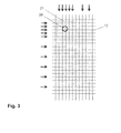
- Fig. 3 shows for example a touch position 30 which has been detected in step 21.
- the predetermined distance may comprise a distance in the direction of the rows and a distance in the direction of the columns.
- the first touch sensor set comprises all touch sensors within the dashed square 31.
- a second touch sensor set is determined comprising those touch sensors which are arranged outside the predetermined distance to the touch position 30. Therefore, with reference to Fig. 3 , the second touch sensor set comprises all touch sensors which are arranged outside the square 31.
- the touch sensors of the first touch sensor set and a proper subset of the touch sensors of the second touch sensor set are scanned. This will be explained in more detail in connection with Fig. 3 .
- step 24 all touch sensors within the square 31 are scanned.
- the corresponding rows and columns are marked with arrows in Fig. 3 . Additionally, only a proper subset of the remaining touch sensors are scanned.
- the corresponding rows and columns of these touch sensors are also indicated by the arrows in Fig. 3 .
- the touch panel 12 is touched at a single point 30. In the area indicated by the square 31 where the touching object is detected, every channel is going to the scanned to get the correct accuracy and sensitivity.
- the other parts of the touch panel 12 will be scanned, but only every other or only every third channel, as indicated in Fig. 3 , is scanned.
- This number could be varied depending on the sensor pitch and the numbers of channel. In this example, only 70 nodes are scanned instead of 276. Therefore, in this case, the scan rate can be increased by almost a factor of four without reducing spatial resolution. However, it is still possible to detect another event on the touch panel and thus the full touch area is covered.
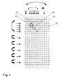
- Fig. 4 shows the partial touch sensor scanning if the touching object, for example a finger, is moved. If the finger is moved in any direction, the scan areas will follow. However, additionally a prediction algorithm may be used to predict a future touch position based on a detected speed and direction of the movement of the touching object. For example, a touch has been detected at the location indicated by the reference sign 30 in Fig. 4 , and a moving direction in the direction of arrow 41 and a moving speed have been determined based on past touch detections. Based on the determined direction 41 and the determined speed of the touching object, a future touch position 40 can be predicted. Therefore, the first touch sensor set is adapted accordingly to the predicted touch position 40 as indicated by the square 42.
- a prediction algorithm may be used to predict a future touch position based on a detected speed and direction of the movement of the touching object. For example, a touch has been detected at the location indicated by the reference sign 30 in Fig. 4 , and a moving direction in the direction of arrow 41 and a moving speed have been determined
- the sensors within the square 42 will be scanned completely and the touch sensors outside the square 42 will be scanned partially as described above.
- the rows and columns which are to be scanned are moving together with the detected touch position and the predicted touch position.
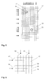
- Fig. 5 shows a case in which two objects are touching the touch panel 12.
- a corresponding first touch sensor set 51, 53 is determined which will be scanned completely during a next scan, and a second touch sensor set comprising the remaining touch sensors will be only scanned partly in the next scan.
- the first touch sensor set associated with the touch position 50 is indicated by the square 51 and the second touch sensor set associated with the touch position 52 is indicated by the square 53.
- 108 sensors need to be scanned instead of 276. Therefore, the partial scanning enables even in case of two touch positions to double the scanning speed.
- two touch positions are shown in connection with the partial scanning of the touch panel, the present invention is not restricted to two touch positions. Rather, the partial scanning may be combined advantageously with any number of touch positions, e.g. three or more touch positions, especially in connection with larger touch panels of e.g. tablet PCs.
- scanning latency can be improved. For example, if a touch panel can be scanned 60 times per second with a complete non-partial scan, the scan frequency can be increased to 240 scans per second when only one object is touching the touch panel and still to 120 scans per second when two objects are touching the touch panel.
- Fig. 6 shows a way to improve the special resolution for detecting a touch position.
- the corresponding control device 16 needs to provide a larger number of interface ports 17 for controlling the increased number of rows and columns.
- control devices may not be available or may be available at higher cost only.
- multiplexers may be used to couple the rows and columns of the grid of the touch panel to the restricted number of interface ports of the control device 16.
- every interface port may be coupled to a 3-to-1-multiplexer and each of the multiplexers may be coupled to three rows or columns of the grid of the touch panel 12.
- the control device can scan a considerable larger number of touch sensors which may increase the spatial accuracy for detecting a touch position where an object touches the touch panel 12, especially in case the object used to touch the touch panel comprises a pen-like stylus.
Landscapes
- Engineering & Computer Science (AREA)
- General Engineering & Computer Science (AREA)
- Theoretical Computer Science (AREA)
- Human Computer Interaction (AREA)
- Physics & Mathematics (AREA)
- General Physics & Mathematics (AREA)
- Position Input By Displaying (AREA)
Priority Applications (1)
| Application Number | Priority Date | Filing Date | Title |
|---|---|---|---|
| EP13177962.1A EP2829953A1 (de) | 2013-07-25 | 2013-07-25 | Verfahren zum Betreiben eines Berührungsbildschirms |
Applications Claiming Priority (1)
| Application Number | Priority Date | Filing Date | Title |
|---|---|---|---|
| EP13177962.1A EP2829953A1 (de) | 2013-07-25 | 2013-07-25 | Verfahren zum Betreiben eines Berührungsbildschirms |
Publications (1)
| Publication Number | Publication Date |
|---|---|
| EP2829953A1 true EP2829953A1 (de) | 2015-01-28 |
Family
ID=48874872
Family Applications (1)
| Application Number | Title | Priority Date | Filing Date |
|---|---|---|---|
| EP13177962.1A Withdrawn EP2829953A1 (de) | 2013-07-25 | 2013-07-25 | Verfahren zum Betreiben eines Berührungsbildschirms |
Country Status (1)
| Country | Link |
|---|---|
| EP (1) | EP2829953A1 (de) |
Cited By (2)
| Publication number | Priority date | Publication date | Assignee | Title |
|---|---|---|---|---|
| WO2018085168A1 (en) * | 2016-11-04 | 2018-05-11 | Microsoft Technology Licensing, Llc | Locating an active stylus over a capacitive sensor |
| CN109923513A (zh) * | 2016-09-09 | 2019-06-21 | 森赛尔股份有限公司 | 用于检测和表征触摸传感器上的输入的系统 |
Citations (5)
| Publication number | Priority date | Publication date | Assignee | Title |
|---|---|---|---|---|
| US20090184934A1 (en) * | 2008-01-17 | 2009-07-23 | Jao-Ching Lin | Method For Determining The Number Of Fingers On A Sensing Device |
| US20100149110A1 (en) * | 2008-12-12 | 2010-06-17 | Wacom Co., Ltd. | Architecture and method for multi-aspect touchscreen scanning |
| US20100283752A1 (en) * | 2009-05-07 | 2010-11-11 | Panasonic Corporation | Capacitive touch panel and method for detecting touched input position on the same |
| US20110248950A1 (en) * | 2010-04-13 | 2011-10-13 | Himax Technologies Limited | Scanning method of a touch panel |
| US20130100071A1 (en) * | 2009-07-28 | 2013-04-25 | Cypress Semiconductor Corporation | Predictive Touch Surface Scanning |
-
2013
- 2013-07-25 EP EP13177962.1A patent/EP2829953A1/de not_active Withdrawn
Patent Citations (5)
| Publication number | Priority date | Publication date | Assignee | Title |
|---|---|---|---|---|
| US20090184934A1 (en) * | 2008-01-17 | 2009-07-23 | Jao-Ching Lin | Method For Determining The Number Of Fingers On A Sensing Device |
| US20100149110A1 (en) * | 2008-12-12 | 2010-06-17 | Wacom Co., Ltd. | Architecture and method for multi-aspect touchscreen scanning |
| US20100283752A1 (en) * | 2009-05-07 | 2010-11-11 | Panasonic Corporation | Capacitive touch panel and method for detecting touched input position on the same |
| US20130100071A1 (en) * | 2009-07-28 | 2013-04-25 | Cypress Semiconductor Corporation | Predictive Touch Surface Scanning |
| US20110248950A1 (en) * | 2010-04-13 | 2011-10-13 | Himax Technologies Limited | Scanning method of a touch panel |
Cited By (11)
| Publication number | Priority date | Publication date | Assignee | Title |
|---|---|---|---|---|
| CN109923513A (zh) * | 2016-09-09 | 2019-06-21 | 森赛尔股份有限公司 | 用于检测和表征触摸传感器上的输入的系统 |
| EP3510476A4 (de) * | 2016-09-09 | 2020-04-15 | Sensel Inc. | System zur erkennung und charakterisierung von eingaben bei einem berührungssensor |
| CN109923513B (zh) * | 2016-09-09 | 2022-06-03 | 森赛尔股份有限公司 | 用于检测和表征触摸传感器上的输入的系统 |
| CN115268753A (zh) * | 2016-09-09 | 2022-11-01 | 森赛尔股份有限公司 | 用于检测和表征触摸传感器上的输入的系统 |
| CN115268753B (zh) * | 2016-09-09 | 2023-08-22 | 森赛尔股份有限公司 | 用于检测和表征触摸传感器上的输入的系统 |
| WO2018085168A1 (en) * | 2016-11-04 | 2018-05-11 | Microsoft Technology Licensing, Llc | Locating an active stylus over a capacitive sensor |
| US10203778B2 (en) | 2016-11-04 | 2019-02-12 | Microsoft Technology Licensing, Llc | Active stylus motion vector |
| CN109906428A (zh) * | 2016-11-04 | 2019-06-18 | 微软技术许可有限责任公司 | 在电容传感器上定位有源触控笔 |
| EP3535649A1 (de) * | 2016-11-04 | 2019-09-11 | Microsoft Technology Licensing, LLC | Lokalisierung eines aktiven stift über einen kapazitiven sensor |
| CN109906428B (zh) * | 2016-11-04 | 2022-08-26 | 微软技术许可有限责任公司 | 在电容传感器上定位有源触控笔的方法和系统 |
| EP3535649B1 (de) * | 2016-11-04 | 2025-09-03 | Microsoft Technology Licensing, LLC | Lokalisierung eines aktiven stift über einen kapazitiven sensor |
Similar Documents
| Publication | Publication Date | Title |
|---|---|---|
| US11036307B2 (en) | Touch sensitive mechanical keyboard | |
| EP3248087B1 (de) | Multichip-berührungsarchitektur für skalierbarkeit | |
| US8773386B2 (en) | Methods and apparatus to scan a targeted portion of an input device to detect a presence | |
| US7659887B2 (en) | Keyboard with a touchpad layer on keys | |
| US8325147B2 (en) | Touch screen device and methods thereof configured for a plurality of resolutions | |
| KR101378511B1 (ko) | 터치 패널에서 노이즈를 최소화하기 위한 방법, 터치 감지 장치 및 컴퓨터 판독 가능한 기록 매체 | |
| US8730187B2 (en) | Techniques for sorting data that represents touch positions on a sensing device | |
| US20090128516A1 (en) | Multi-point detection on a single-point detection digitizer | |
| US8368667B2 (en) | Method for reducing latency when using multi-touch gesture on touchpad | |
| JP6558704B2 (ja) | 非表示更新期間後の表示アーチファクトの低減 | |
| WO2011042814A1 (en) | Methods and devices that resize touch selection zones while selected on a touch sensitive display | |
| KR20150083437A (ko) | 통합된 입력 디바이스에서의 전극 간섭의 완화 | |
| TWI614652B (zh) | 具有內建觸控螢幕之顯示面板及包含該顯示面板的觸控顯示裝置 | |
| CN102207781A (zh) | 具有改进分辨率的触摸输入装置 | |
| WO2012129973A1 (en) | Method of identifying multi-touch scaling gesture and device using the same | |
| CN105094487B (zh) | 触摸屏及其控制方法、控制装置、触摸显示装置 | |
| US9342196B2 (en) | Hardware accelerator for touchscreen data processing | |
| EP2829953A1 (de) | Verfahren zum Betreiben eines Berührungsbildschirms | |
| KR20170044793A (ko) | 터치 감지부, 이를 포함하는 터치 스크린 패널 및 터치 스크린 패널의 구동 방법 | |
| GB2481606A (en) | Fine movement of an object displayed on an interactive surface having a display resolution greater than its detection resolution | |
| US8922524B2 (en) | Touch sensing device and electronic system including the same | |
| KR101715997B1 (ko) | 정전용량 터치패널용 구동 방법 및 장치 | |
| US20140317568A1 (en) | Information processing apparatus, information processing method, program, and information processing system | |
| US20150346905A1 (en) | Modifying an on-screen keyboard based on asymmetric touch drift | |
| CN102681702A (zh) | 控制方法、控制装置以及电子设备 |
Legal Events
| Date | Code | Title | Description |
|---|---|---|---|
| 17P | Request for examination filed |
Effective date: 20130725 |
|
| AK | Designated contracting states |
Kind code of ref document: A1 Designated state(s): AL AT BE BG CH CY CZ DE DK EE ES FI FR GB GR HR HU IE IS IT LI LT LU LV MC MK MT NL NO PL PT RO RS SE SI SK SM TR |
|
| AX | Request for extension of the european patent |
Extension state: BA ME |
|
| PUAI | Public reference made under article 153(3) epc to a published international application that has entered the european phase |
Free format text: ORIGINAL CODE: 0009012 |
|
| STAA | Information on the status of an ep patent application or granted ep patent |
Free format text: STATUS: THE APPLICATION IS DEEMED TO BE WITHDRAWN |
|
| 18D | Application deemed to be withdrawn |
Effective date: 20150729 |