EP2829896A2 - Temperaturkompensation für seismischen Sensor und für Verfahren zur Erfassung eines seismischen Signals - Google Patents
Temperaturkompensation für seismischen Sensor und für Verfahren zur Erfassung eines seismischen Signals Download PDFInfo
- Publication number
- EP2829896A2 EP2829896A2 EP14150975.2A EP14150975A EP2829896A2 EP 2829896 A2 EP2829896 A2 EP 2829896A2 EP 14150975 A EP14150975 A EP 14150975A EP 2829896 A2 EP2829896 A2 EP 2829896A2
- Authority
- EP
- European Patent Office
- Prior art keywords
- seismic
- temperature
- damping
- magnet
- seismic sensor
- Prior art date
- Legal status (The legal status is an assumption and is not a legal conclusion. Google has not performed a legal analysis and makes no representation as to the accuracy of the status listed.)
- Withdrawn
Links
- 238000000034 method Methods 0.000 title claims description 33
- 238000013016 damping Methods 0.000 claims abstract description 110
- 230000008859 change Effects 0.000 claims description 24
- 230000000694 effects Effects 0.000 claims description 6
- 238000005259 measurement Methods 0.000 claims description 2
- 230000001419 dependent effect Effects 0.000 abstract 1
- 238000012937 correction Methods 0.000 description 12
- 230000004044 response Effects 0.000 description 9
- 238000013459 approach Methods 0.000 description 5
- 238000010586 diagram Methods 0.000 description 4
- 230000010355 oscillation Effects 0.000 description 4
- 238000012545 processing Methods 0.000 description 4
- 230000007246 mechanism Effects 0.000 description 3
- 230000008569 process Effects 0.000 description 3
- 238000009529 body temperature measurement Methods 0.000 description 2
- 238000004364 calculation method Methods 0.000 description 2
- 230000006870 function Effects 0.000 description 2
- 238000012986 modification Methods 0.000 description 2
- 230000004048 modification Effects 0.000 description 2
- 230000003534 oscillatory effect Effects 0.000 description 2
- 230000008901 benefit Effects 0.000 description 1
- 230000015556 catabolic process Effects 0.000 description 1
- 238000006243 chemical reaction Methods 0.000 description 1
- 238000013500 data storage Methods 0.000 description 1
- 238000006731 degradation reaction Methods 0.000 description 1
- 238000005516 engineering process Methods 0.000 description 1
- 239000002360 explosive Substances 0.000 description 1
- 230000006872 improvement Effects 0.000 description 1
- 238000013178 mathematical model Methods 0.000 description 1
- 230000002277 temperature effect Effects 0.000 description 1
Images


Classifications
-
- G—PHYSICS
- G01—MEASURING; TESTING
- G01V—GEOPHYSICS; GRAVITATIONAL MEASUREMENTS; DETECTING MASSES OR OBJECTS; TAGS
- G01V1/00—Seismology; Seismic or acoustic prospecting or detecting
- G01V1/24—Recording seismic data
-
- G—PHYSICS
- G01—MEASURING; TESTING
- G01V—GEOPHYSICS; GRAVITATIONAL MEASUREMENTS; DETECTING MASSES OR OBJECTS; TAGS
- G01V1/00—Seismology; Seismic or acoustic prospecting or detecting
- G01V1/16—Receiving elements for seismic signals; Arrangements or adaptations of receiving elements
- G01V1/18—Receiving elements, e.g. seismometer, geophone or torque detectors, for localised single point measurements
- G01V1/181—Geophones
- G01V1/182—Geophones with moving coil
-
- G—PHYSICS
- G01—MEASURING; TESTING
- G01V—GEOPHYSICS; GRAVITATIONAL MEASUREMENTS; DETECTING MASSES OR OBJECTS; TAGS
- G01V1/00—Seismology; Seismic or acoustic prospecting or detecting
- G01V1/16—Receiving elements for seismic signals; Arrangements or adaptations of receiving elements
- G01V1/162—Details
-
- G—PHYSICS
- G01—MEASURING; TESTING
- G01V—GEOPHYSICS; GRAVITATIONAL MEASUREMENTS; DETECTING MASSES OR OBJECTS; TAGS
- G01V1/00—Seismology; Seismic or acoustic prospecting or detecting
- G01V1/28—Processing seismic data, e.g. for interpretation or for event detection
- G01V1/36—Effecting static or dynamic corrections on records, e.g. correcting spread; Correlating seismic signals; Eliminating effects of unwanted energy
-
- G—PHYSICS
- G01—MEASURING; TESTING
- G01D—MEASURING NOT SPECIALLY ADAPTED FOR A SPECIFIC VARIABLE; ARRANGEMENTS FOR MEASURING TWO OR MORE VARIABLES NOT COVERED IN A SINGLE OTHER SUBCLASS; TARIFF METERING APPARATUS; MEASURING OR TESTING NOT OTHERWISE PROVIDED FOR
- G01D3/00—Indicating or recording apparatus with provision for the special purposes referred to in the subgroups
- G01D3/028—Indicating or recording apparatus with provision for the special purposes referred to in the subgroups mitigating undesired influences, e.g. temperature, pressure
-
- G—PHYSICS
- G01—MEASURING; TESTING
- G01V—GEOPHYSICS; GRAVITATIONAL MEASUREMENTS; DETECTING MASSES OR OBJECTS; TAGS
- G01V2210/00—Details of seismic processing or analysis
- G01V2210/20—Trace signal pre-filtering to select, remove or transform specific events or signal components, i.e. trace-in/trace-out
- G01V2210/27—Other pre-filtering
Definitions
- Embodiments of the subject matter disclosed herein generally relate to sensors for collecting seismic or similar data and, more particularly, to mechanisms and techniques for correcting a temperature-induced phase change of a recording signal during a seismic survey.
- Seismic data acquisition and processing may be used to generate a profile (image) of the geophysical structure under the ground (either on land or seabed). While this profile does not provide an exact location for oil and gas reservoirs, it suggests, to those trained in the field, the presence or absence of such reservoirs. Thus, providing a high-resolution image of the subsurface of the earth is important, for example, to those who need to determine where oil and gas reservoirs are located.
- a land seismic survey system 10 is generally configured as illustrated in Figure 1 , although many other configurations are used.
- System 10 includes plural receivers 12 and acquisition units 12a positioned over an area 13 of a subsurface to be explored and in contact with the surface 14 of the ground.
- a number of vibroseismic or other types of sources 16 are also placed on surface 14 in an area 17, in a vicinity of area 13 of receivers 12.
- a recording device 18 is connected to a plurality of receivers 12 and placed, for example, in a station-truck 20.
- Each source 16 may be composed of a variable number of vibrators or explosive devices, typically between 1 and 5, and may include a local controller 22.
- a central controller 24 may be present to coordinate the shooting times of the sources 16.
- a GPS system 26 may be used to time-correlate sources 16 and receivers 12 and/or acquisition units 12a.
- sources 16 are controlled to generate seismic waves, and the plurality of receivers 12 record waves reflected by oil and/or gas reservoirs and other structures.
- the seismic survey may last for days, or it may be repeated at various time intervals, e.g., months or years apart, to determine the original shape or changes in the monitored reservoirs. Either way, daily temperature changes occur during the life of the seismic survey, and they negatively impact the quality of the recorded signals as now discussed.
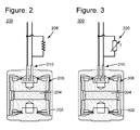
- Receiver 12 may be a geophone having a structure as illustrated in Figure 2 .
- This structure may be found in other transducers that transform mechanical energy into electrical energy, i.e., seismometer, or any other device that uses a magnet field for energy conversion.
- this application refers herein to a geophone, but the novel operation principle described herein also applies for other types of transducers.
- Geophone 200 has a casing 202 that houses a magnet 204 and a coil assembly 206.
- Coil assembly 206 is electrically connected to terminals 210, and these terminals may be electrically connected to an optional damping resistor 208. When in use, the casing 202 moves in response to seismic waves in the earth.
- Either the coil assembly 206 or the magnet 204 is attached to the casing 202 and the mass of the other is suspended in such a way as to cause relative movement between the coil assembly 206 and the magnet 204.
- This movement of coil assembly 206 relative to magnet 204 produces a back electro-magnetic force (emf) in the wires of the coil assembly.
- emf electro-magnetic force
- damping resistor 208 When damping resistor 208 is present, the back emf generates a current through terminals 210 and resistor 208. Voltage across terminals 210 is measured and considered to be indicative of the seismic signal to be recorded.
- a signal (having an amplitude and a phase) is recorded by the geophone 200 based on the voltage across optional damping resistor 208.
- Intrinsic damping is provided by eddy currents that appear in the coil support mechanism, which in turn generate a magnetic field opposing the magnetic field generated by magnet 204.
- a second type of damping may be provided by adding damping resistor 208, which has a resistance calculated in such a way to optimize the assembly motion.
- the calculated value of the damping resistor 208 is only effective for a given temperature. If the ambient temperature of the geophone changes as noted above, there can be no unique match between a fixed resistor and the magnetic field temperature profile. Thus, even with a precision damping resistor 208, the geophone is prone to introducing phase errors into the measured signal when the temperature deviates from the nominal temperature for which the resistance of the damping resistor has been calculated.
- phase errors introduced by the geophones because of variations in their magnetic properties may be significant.
- phase differences it has been observed that two identical geophones simultaneously recording seismic waves, one in shade and one in full sun, recorded the corresponding signals with a phase difference of up to 20 degrees.
- This large phase difference in recorded signals introduces inaccuracies when the central recording unit or other processing units add together several recorded signals in a process commonly called stacking or utilizes other mathematical processes.
- magnets that are not temperature-sensitive, i.e., magnets with low thermal coefficients.
- magnets are expensive and may have their own limitations because any magnet is, to a certain degree, temperature-sensitive.
- these low-thermal-coefficient magnets have geometric limitations.
- a seismic sensor for detecting a characteristic of a medium during a seismic survey.
- the sensor includes a casing; a magnet located inside the casing; a coil assembly located inside the casing, wherein the coil assembly moves relative to the magnet; and a temperature-sensitive device connected to terminals of the coil assembly and configured to generate a compensated damping.
- the magnet and the coil assembly produce a temperature-sensitive intrinsic damping and the temperature-sensitive device produces an additional damping that is selected to counterbalance the temperature-sensitive intrinsic damping to obtain a compensated damping that reduces effects of a changing magnetic field so that a phase of a recorded seismic signal is compensated for temperature-induced magnetic field changes.
- the compensated damping that is a sum of the temperature-sensitive intrinsic damping and the additional damping of the temperature-sensitive device may be about constant over a given range of temperatures.
- the magnet may for example generate a magnetic field that changes with temperature.
- the temperature-sensitive device may include a thermistor.
- the temperature-sensitive device may alternatively include a thermistor and a resistor.
- the temperature-sensitive device may include a plurality of thermistors and fixed resistors.
- the compensated damping may be selected to have a predetermined value at a nominal temperature.
- the predetermined value of damping may be 70%.
- the seismic sensor may be a geophone.
- a method for detecting a characteristic of a medium during a seismic survey includes placing a seismic sensor on ground, wherein the seismic sensor includes a casing, a magnet located inside the casing, a coil assembly located inside the casing, wherein the coil assembly moves relative to the magnet, and a temperature-sensitive device is connected to terminals of the coil assembly; measuring with the seismic sensor a seismic signal; generating with the magnet and the coil assembly an intrinsic damping; and generating with the temperature-sensitive device an additional damping that together with the intrinsic damping form a compensated damping so that a phase of a recorded seismic signal is compensated for temperature-induced magnetic field changes.
- a method for adjusting a phase of a seismic signal recorded with a seismic sensor includes receiving magnet characteristics of a magnet that is part of the seismic sensor; receiving the recorded seismic signal; receiving an ambient temperature of the seismic sensor; calculating, in a processor, a new phase for the recorded seismic sensor based on the magnet characteristics, the recorded seismic signal and the ambient temperature; and replacing an original phase of the recorded seismic signal with the new phase.
- Such method may further comprise:
- the method may further comprise:
- the step of calculating may be performed in the seismic sensor and the ambient temperature is measured in the seismic sensor.
- the step of calculating may be performed in a remote acquisition unit linked to one or more seismic sensors.
- the step of calculating may be performed in a base station that communicates with one or more seismic sensors.
- the method may further comprise:
- the method may further comprise:
- a seismic survey system configured to adjust a phase of a recorded seismic signal.
- the system includes plural seismic sensors configured to record seismic signals; plural remote acquisition units or base stations configured to receive the seismic signals from the plural seismic sensors; and a processor.
- the processor is configured to receive magnet characteristics of a magnet that is part of a given seismic sensor, receive the recorded seismic signal associated with given seismic sensor, receive an ambient temperature of the given seismic sensor, calculate a new phase for the recorded seismic signal based on the magnet characteristics, the recorded seismic signal and the ambient temperature, and replace an original phase of the recorded seismic signal with the new phase.
- an original phase of each recorded seismic signal of each seismic sensor may be replaced with a corresponding new phase.
- a seismic or other type of vibration sensor for detecting a characteristic of a medium during a seismic survey.
- the seismic sensor includes a casing, a magnet located inside the casing, a coil assembly located inside the casing, and a temperature-sensitive device connected to terminals of the coil assembly and configured to optimize damping.
- the magnet and coil assembly produce intrinsic damping which changes with temperature.
- the temperature-sensitive device is selected to counterbalance the temperature effects of the intrinsic damping so that the phase of a recorded seismic signal is compensated for the temperature-induced magnetic field changes.
- Geophone 300 that achieves a more temperature-constant electromagnetic damping is illustrated in Figure 3 .
- Geophone 300 has a casing 302 in which a magnet 304 and a coil assembly 306 are housed. The magnet and the coil assembly are configured to move relative to each other, thus, producing a back emf at terminals 310.
- the novel geophone has a temperature-sensitive unit 320 that provides a near-constant electromagnetic damping. This near-constant electromagnetic damping is achieved as discussed next.
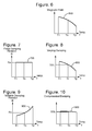
- Figure 4 shows the frequency response of a typical geophone at a nominal temperature Tn with several different damping resistors. Less damping causes a higher peak in the frequency domain which means more cycles of oscillation in the time domain.
- This frequency response will change when the ambient temperature deviates from Tn primarily due to the magnetic field strength changing with temperature but also due to other temperature sensitive characteristics.
- Figure 5 shows a plot of the damping of this typical geophone with a change in damping resistance. It clearly shows a generally negative slope. Thus, the damping of this typical geophone can be changed over a large range by selecting an appropriate damping resistor. Curve 500 shows that increasing the damping resistance will decrease the damping for this particular geophone.
- Figure 6 illustrates a curve 600 corresponding to the variation of a magnetic field B generated by a magnet as a function of the ambient temperature T.
- the curve is plotted between temperatures T1 and T2, which determine a temperature range of interest for the geophones.
- Curve 600 may vary for different magnets, but the illustrated profile is considered a good approximation for many existing magnets.
- the traditional fixed damping resistor has a relatively constant value of Ro at all temperatures.
- Curve 700 is actually shown as a straight line in Figure 7 .
- the damping associated with varying magnetic field B and the traditional fixed resistor Ro is shown as curve 800 in Figure 8 .
- the damping associated with a traditional resistor e.g., resistor 208 deviates from the desired damping at Tn as the temperature deviates from Tn because the magnetic field B has changed with temperature without a commensurate change in damping resistor.
- the total damping illustrated as curve 800 in Figure 8 , shows a variation over the range of interest T1 to T2, resulting in signal degradation (i.e., phase modifications) as the temperature of the sensor deviates from the nominal temperature Tn.
- the temperature-sensitive device may be designed in such a way that its resistance changes with temperature as illustrated by curve 900 in Figure 9 .
- the shape of curve 900 is chosen to counteract the effects of the change in damping in curve 800 due to the change in magnetic field in curve 600 as closely as possible.
- the resulting damping at any given temperature in a given range, which is illustrated as curve 1000 in Figure 10 results in damping that is substantially flat with temperature.
- magnet 304 and coil assembly 306 produce an intrinsic damping and the temperature-sensitive device 320 produces an additional damping that is selected to counterbalance the intrinsic damping to obtain a compensated damping (1000) that reduces effects of a changing magnetic field (600) so that a phase of a recorded seismic signal is compensated for temperature-induced magnetic field changes.
- the resulting damping in curve 1000 for the geophone of Figure 3 does not change (or changes minimally) over the temperature range T1 to T2. This is different from the resulting damping in curve 800 for the geophone of Figure 2 .
- the goal for determining the resistance versus temperature shape of curve 900 is to apply the resistance versus damping characteristics shown in the shape of curve 500 to the uncompensated damping versus temperature shape of curve 800, to create the compensated damping versus temperature shape of curve 1000.
- An effective way to determine the shape of curve 900 empirically and accommodate all temperature-sensitive characteristics is to determine the resistance needed to achieve the typical 70% damping at several different temperatures.
- a PTC (Positive Temperature Coefficient) thermistor or a network of PTC, NTC (Negative Temperature Coefficient) thermistor and a fixed resistor can generally create the shape of curve 900 to one sufficiently skilled in the art. Note that in practice, curve 1000 may not be exactly flat. However, as long as the damping stays significantly closer to the typically desired 70% than the uncompensated damping in curve 800 of traditional devices, the geophone with such a temperature-sensitive device better describes the actual phase of the seismic wave.
- the temperature-sensitive device 320 may achieve curve 1000 by using a thermistor or a combination of thermistors.
- the thermistor or network of thermistors is a preferred embodiment because of their low cost.
- other temperature-sensitive devices may be used.
- a thermistor is a resistor whose resistance varies more than a conventional resistor with the ambient temperature and in a predictable manner.
- thermistor By using a single thermistor or by combining a given number of thermistors and fixed resistors, it is possible to achieve damping having a desired shape, for example, the shape of curve 1000 in Figure 10 .
- a single thermistor or a plurality of thermistors (grouped in series, parallel, or combinations of series and parallel) for achieving a desired temperature-sensitive device.
- the choice of thermistors depends upon the actual shape of curves 500 and 800 for a specific geophone.
- Other electrical components may be added as will be recognized by those skilled in the art.
- not all the geophones are provided with the temperature-sensitive device 320. For example, it is possible for a fraction of the total geophones to be used for a seismic survey to be fitted with the temperature-sensitive device.
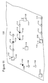
- a seismic survey system 1100 may include a central control unit 1102 that communicates with a harvester unit 1104.
- Harvester unit 1104 (which may be located on a truck, boat, airplane, etc.) may interact with remote acquisition units 1106 or with wireless seismic sensors 1108.
- Remote acquisition units 1106 may communicate with one or more corresponding seismic sensors 1112 for collecting the recorded seismic data. If harvester unit 1104 is not present, one or more base stations 1110 may be used to collect seismic data from individual seismic sensors 1112 and to transmit it to central control unit 1102.
- the temperature correction algorithm may reside in a memory associated with a processor (to be discussed later) and may perform the following calculations.
- the processor may receive characteristics of the magnet associated with a given geophone.
- the processor receives the signal recorded by the geophone, and in step 1204 it also receives the ambient temperature corresponding to the recorded signal. Based on a mathematical model retrieved in step 1206, the processor calculates in step 1208 a new phase for the recorded signal and replaces the recorded phase with the new phase.
- This calculation step may involve calculating or predicting a change in the magnetic field for the detected temperature change, and the modified recorded signal is then used, for further processing (e.g., stacking the seismic signals with the new phases) in step 1210, and for generating an image of the surveyed surface in step 1212.
- modern geophones 1112 have a digital seismic unit (1112a and 1108a), and this unit may have the capability to run the temperature correction algorithm discussed with regard to Figure 12 . Not all the seismic sensors need to run the temperature correction algorithm.
- remote acquisition units 1106 and/or base stations 1110 have a corresponding processor 1120 that can also run the temperature correction algorithm.
- the temperature correction algorithm may be implemented in the harvester unit 1104 or in the central control unit 1102. The ambient temperature measurement may take place at the sensor level or at the base station or remote acquisition unit level if the spread of sensors is at the same temperature. In one application, the temperature correction algorithm is performed at the base station or remote acquisition unit or central control unit while the temperature is measured at the sensor level.
- both the temperature correction algorithm and the temperature measurement are performed at the same level, i.e., at the seismic sensor, base station or remote acquisition unit.
- the temperature correction algorithm is run at the seismic sensor level, or the base station level, or the remote acquisition unit level or at the central control unit level, it is possible to correct the phase of the recorded signal through software instead of adding hardware components (e.g., temperature-sensitive devices).
- the processor that runs the temperature correction algorithm needs to receive the ambient temperature of the sensor.
- the ambient temperature of the sensor There are various approaches to measure the ambient temperature. For simplicity, only two such approaches are discussed next.
- One approach will be to have a temperature sensor installed on the seismic sensor. Not all the seismic sensors need to have a temperature sensor. However, the more seismic sensors that have the temperature sensors, the better the quality of the overall recorded seismic data.
- temperature sensors are installed on the remote acquisition units 1106 and/or on the base stations 1110.
- the resistivity vs. temperature characteristic graph of the resistor 208 (which is well-known for a given resistor and may be stored in the memory of the processor) may be used to determine the ambient temperature by actually measuring the resistivity of the resistor and using the above graph to calculate the temperature. This last approach may also be implemented at the base station and/or the remote acquisition units. Thus, for this approach, no independent temperature sensor is needed because the temperature-sensitive damping resistor may be used to measure the temperature.
- One advantage of the novel embodiments discussed above is that inexpensive magnets may be used for the seismic sensors. While expensive magnets may be designed to have a near-constant electromagnetic damping, the above-discussed embodiments provide a different way for achieving electromagnetic damping, which is inexpensive and easy to implement. Also, the novel embodiments allow existing seismic sensors to be software-updated to implement the temperature correction algorithm with minimum disruption.
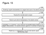
- the method includes a step 1300 of receiving magnet characteristics of a magnet that is part of the seismic sensor; a step 1302 of receiving the recorded seismic signal; a step 1304 of receiving an ambient temperature of the seismic sensor; a step 1306 of calculating, in a processor, a new phase for the recorded seismic sensor based on the magnet characteristics, the recorded seismic signal and the ambient temperature; and a step 1308 of correcting the original phase of the recorded seismic signal with the new phase.
- the above method and others may be implemented in a computing system specifically configured to receive and/or process the data from the seismic sensor.
- An example of a representative computing system capable of carrying out operations in accordance with the exemplary embodiments is illustrated in Figure 14 .
- Hardware, firmware, software or a combination thereof may be used to perform the various steps and operations described herein.
- the computing system may be part of the seismic sensor 1112, or 1108, or remote acquisition unit 1106, or base station 1110, or harvester unit 1104, or it may be part of the central unit 1102.
- the exemplary computing system 1400 suitable for performing the activities described in the exemplary embodiments may include server 1401.
- a server 1401 may include a central processor (CPU) 1402 coupled to a random access memory (RAM) 1404 and to a read-only memory (ROM) 1406.
- the ROM 1406 may also be other types of storage media to store programs, such as programmable ROM (PROM), erasable PROM (EPROM), etc.
- the processor 1402 may communicate with other internal and external components through input/output (I/O) circuitry 1408 and bussing 1410 to provide control signals and the like.
- the processor 1402 carries out a variety of functions as are known in the art, as dictated by software and/or firmware instructions.
- the server 1401 may also include one or more data storage devices, including a hard drive 1412, CD-ROM drives 1414, and other hardware capable of reading and/or storing information such as DVD, etc.
- software for carrying out the above-discussed steps may be stored and distributed on a CD-ROM 1416, removable memory device 1418 or other form of media capable of portably storing information. These storage media may be inserted into, and read by, devices such as the CD-ROM drive 1414, the disk drive 1412, etc.
- the server 1401 may be coupled to a display 1420, which may be any type of known display or presentation screen, such as LCD, LED displays, plasma display, cathode ray tubes (CRT), etc.
- a user input interface 1422 is provided, including one or more user interface mechanisms such as a mouse, keyboard, microphone, touch pad, touch screen, voice-recognition system, etc.
- the server 1401 may be coupled to other computing devices, such as a landline and/or wireless terminals via a network.
- the server may be part of a larger network configuration as in a global area network (GAN) such as the Internet 1428, which allows ultimate connection to various landline and/or mobile client devices.
- GAN global area network
- the computing device may be implemented on a vehicle that performs a land seismic survey.
- the disclosed exemplary embodiments provide a system and a method for compensating temperature-induced magnetic field changes in a seismic sensor. It should be understood that this description is not intended to limit the invention. On the contrary, the exemplary embodiments are intended to cover alternatives, modifications and equivalents, which are included in the spirit and scope of the invention as defined by the appended claims. Further, in the detailed description of the exemplary embodiments, numerous specific details are set forth in order to provide a comprehensive understanding of the claimed invention. However, one skilled in the art would understand that various embodiments may be practiced without such specific details.
Landscapes
- Physics & Mathematics (AREA)
- Life Sciences & Earth Sciences (AREA)
- Engineering & Computer Science (AREA)
- Remote Sensing (AREA)
- Acoustics & Sound (AREA)
- Environmental & Geological Engineering (AREA)
- Geology (AREA)
- General Life Sciences & Earth Sciences (AREA)
- General Physics & Mathematics (AREA)
- Geophysics (AREA)
- Geophysics And Detection Of Objects (AREA)
- Measurement Of Mechanical Vibrations Or Ultrasonic Waves (AREA)
Applications Claiming Priority (1)
| Application Number | Priority Date | Filing Date | Title |
|---|---|---|---|
| US13/950,747 US9389324B2 (en) | 2013-07-25 | 2013-07-25 | Temperature compensation for seismic sensor and method |
Publications (2)
| Publication Number | Publication Date |
|---|---|
| EP2829896A2 true EP2829896A2 (de) | 2015-01-28 |
| EP2829896A3 EP2829896A3 (de) | 2016-03-16 |
Family
ID=49917026
Family Applications (1)
| Application Number | Title | Priority Date | Filing Date |
|---|---|---|---|
| EP14150975.2A Withdrawn EP2829896A3 (de) | 2013-07-25 | 2014-01-13 | Temperaturkompensation für seismischen Sensor und für Verfahren zur Erfassung eines seismischen Signals |
Country Status (2)
| Country | Link |
|---|---|
| US (1) | US9389324B2 (de) |
| EP (1) | EP2829896A3 (de) |
Cited By (2)
| Publication number | Priority date | Publication date | Assignee | Title |
|---|---|---|---|---|
| RU2677951C1 (ru) * | 2017-10-16 | 2019-01-22 | Федеральное государственное казенное учреждение "12 Центральный научно-исследовательский институт" Министерства обороны Российской Федерации | Жидкостной измеритель скорости |
| CN113109153A (zh) * | 2021-04-29 | 2021-07-13 | 长安大学 | 一种适用于固结设备的阻尼比测量装置及信号处理方法 |
Families Citing this family (3)
| Publication number | Priority date | Publication date | Assignee | Title |
|---|---|---|---|---|
| EP3864979A1 (de) | 2014-07-24 | 2021-08-18 | Altria Client Services LLC | Verfahren zum erzeugen eines dampfes mittels einer elektronischen dampfvorrichtung |
| US10684148B2 (en) | 2018-07-10 | 2020-06-16 | Epro Gmbh | Temperature compensation for eddy current sensors |
| CN109597118B (zh) * | 2018-10-17 | 2020-12-08 | 彭章义 | 一种预测地震位置和地震波波击范围的温度波圈板 |
Family Cites Families (7)
| Publication number | Priority date | Publication date | Assignee | Title |
|---|---|---|---|---|
| US4128010A (en) | 1977-09-21 | 1978-12-05 | Honeywell Inc. | Temperature compensated permanent magnet/moving coil accelerometer |
| US4334296A (en) * | 1978-03-16 | 1982-06-08 | Western Geophysical Co. Of America | Seismic method and apparatus |
| US4504932A (en) * | 1982-02-08 | 1985-03-12 | Metrix Instrument Co. | Geophone having a non-conductive coilform |
| NL8202309A (nl) * | 1982-06-08 | 1984-01-02 | Regt Special Cable Bv De | Actieve geofoon, meer in het bijzonder een versnellingsgevoelige geofoon. |
| CA2632105C (en) * | 2005-12-30 | 2015-10-20 | Input/Output, Inc. | Geophone with mass position sensing |
| US8125852B2 (en) | 2009-05-25 | 2012-02-28 | Schlumberger Technology Corporation | Methods and systems for seismic signal detection |
| US8913464B2 (en) | 2010-09-14 | 2014-12-16 | Schlumberger Technology Corporation | Methods and systems for seismic signal detection |
-
2013
- 2013-07-25 US US13/950,747 patent/US9389324B2/en not_active Expired - Fee Related
-
2014
- 2014-01-13 EP EP14150975.2A patent/EP2829896A3/de not_active Withdrawn
Non-Patent Citations (1)
| Title |
|---|
| None |
Cited By (2)
| Publication number | Priority date | Publication date | Assignee | Title |
|---|---|---|---|---|
| RU2677951C1 (ru) * | 2017-10-16 | 2019-01-22 | Федеральное государственное казенное учреждение "12 Центральный научно-исследовательский институт" Министерства обороны Российской Федерации | Жидкостной измеритель скорости |
| CN113109153A (zh) * | 2021-04-29 | 2021-07-13 | 长安大学 | 一种适用于固结设备的阻尼比测量装置及信号处理方法 |
Also Published As
| Publication number | Publication date |
|---|---|
| EP2829896A3 (de) | 2016-03-16 |
| US9389324B2 (en) | 2016-07-12 |
| US20150027229A1 (en) | 2015-01-29 |
Similar Documents
| Publication | Publication Date | Title |
|---|---|---|
| US9389324B2 (en) | Temperature compensation for seismic sensor and method | |
| Wang et al. | An improved automatic scheme for empirical baseline correction of digital strong-motion records | |
| Francis | Performance assessment of the relative gravimeter Scintrex CG-6 | |
| EP2228669A1 (de) | Verfahren und Systeme zur Kalibrierung eines seismischen Sensors | |
| BR102013020149A2 (pt) | dispositivo e método para deconvolução direcional de dados sísmicos | |
| CA2887092C (en) | Electromagnetic receiver tracking and real-time calibration system and method | |
| US20110242933A1 (en) | Determining a characteristic of a seismic sensing module using a processor in the seismic sensing module | |
| EP3092511A1 (de) | Vorrichtung und verfahren zur minderung von zyklusüberspringen in der vollwellenforminversion | |
| US20050201206A1 (en) | Seismic sensors | |
| US20170068014A1 (en) | Systems and methods for a composite magnetic field sensor for airborne geophysical surveys | |
| AU2020267292B2 (en) | Method and system for broadband measurements using multiple electromagnetic receivers | |
| EP3548850A1 (de) | Temperaturkompensation eines in der messgeräteverifizierung verwendeten testtons | |
| US9435644B2 (en) | Digital compensation for non-linearity in displacement sensors | |
| Boucard et al. | Developments in vibrator control | |
| Webb et al. | High-resolution seafloor absolute pressure gauge measurements using a better counting method | |
| US11966252B2 (en) | Clock drift | |
| US20150226554A1 (en) | Seismic streamer shape correction using derived compensated magnetic fields | |
| EP3485297B1 (de) | System und verfahren zur korrektur der antwort eines seismischen sensors | |
| CA3153035C (en) | Correction of clock drift in seismic sensors | |
| US2614432A (en) | Gravity meter | |
| WO2026010507A1 (en) | A method for correcting clock drift |
Legal Events
| Date | Code | Title | Description |
|---|---|---|---|
| 17P | Request for examination filed |
Effective date: 20140113 |
|
| AK | Designated contracting states |
Kind code of ref document: A2 Designated state(s): AL AT BE BG CH CY CZ DE DK EE ES FI FR GB GR HR HU IE IS IT LI LT LU LV MC MK MT NL NO PL PT RO RS SE SI SK SM TR |
|
| AX | Request for extension of the european patent |
Extension state: BA ME |
|
| PUAI | Public reference made under article 153(3) epc to a published international application that has entered the european phase |
Free format text: ORIGINAL CODE: 0009012 |
|
| RIC1 | Information provided on ipc code assigned before grant |
Ipc: G01D 3/028 20060101ALN20151111BHEP Ipc: G01V 1/18 20060101AFI20151111BHEP Ipc: G01V 1/24 20060101ALI20151111BHEP Ipc: G01V 1/16 20060101ALI20151111BHEP Ipc: G01V 1/36 20060101ALI20151111BHEP |
|
| PUAL | Search report despatched |
Free format text: ORIGINAL CODE: 0009013 |
|
| AK | Designated contracting states |
Kind code of ref document: A3 Designated state(s): AL AT BE BG CH CY CZ DE DK EE ES FI FR GB GR HR HU IE IS IT LI LT LU LV MC MK MT NL NO PL PT RO RS SE SI SK SM TR |
|
| AX | Request for extension of the european patent |
Extension state: BA ME |
|
| RIC1 | Information provided on ipc code assigned before grant |
Ipc: G01V 1/24 20060101ALI20160211BHEP Ipc: G01V 1/16 20060101ALI20160211BHEP Ipc: G01V 1/18 20060101AFI20160211BHEP Ipc: G01V 1/36 20060101ALI20160211BHEP Ipc: G01D 3/028 20060101ALN20160211BHEP |
|
| R17P | Request for examination filed (corrected) |
Effective date: 20160830 |
|
| RBV | Designated contracting states (corrected) |
Designated state(s): AL AT BE BG CH CY CZ DE DK EE ES FI FR GB GR HR HU IE IS IT LI LT LU LV MC MK MT NL NO PL PT RO RS SE SI SK SM TR |
|
| GRAP | Despatch of communication of intention to grant a patent |
Free format text: ORIGINAL CODE: EPIDOSNIGR1 |
|
| RIC1 | Information provided on ipc code assigned before grant |
Ipc: G01V 1/24 20060101ALI20170703BHEP Ipc: G01V 1/16 20060101ALI20170703BHEP Ipc: G01V 1/18 20060101AFI20170703BHEP Ipc: G01D 3/028 20060101ALN20170703BHEP Ipc: G01V 1/36 20060101ALI20170703BHEP |
|
| INTG | Intention to grant announced |
Effective date: 20170804 |
|
| RIC1 | Information provided on ipc code assigned before grant |
Ipc: G01V 1/16 20060101ALI20170725BHEP Ipc: G01V 1/18 20060101AFI20170725BHEP Ipc: G01V 1/24 20060101ALI20170725BHEP Ipc: G01V 1/36 20060101ALI20170725BHEP Ipc: G01D 3/028 20060101ALN20170725BHEP |
|
| STAA | Information on the status of an ep patent application or granted ep patent |
Free format text: STATUS: THE APPLICATION IS DEEMED TO BE WITHDRAWN |
|
| 18D | Application deemed to be withdrawn |
Effective date: 20171215 |