EP2829887B1 - Verfahren und Vorrichtung zur Schätzung des Winkels der Spannung im Nullsystem bei einphasigem Erdschluss - Google Patents
Verfahren und Vorrichtung zur Schätzung des Winkels der Spannung im Nullsystem bei einphasigem Erdschluss Download PDFInfo
- Publication number
- EP2829887B1 EP2829887B1 EP14305836.0A EP14305836A EP2829887B1 EP 2829887 B1 EP2829887 B1 EP 2829887B1 EP 14305836 A EP14305836 A EP 14305836A EP 2829887 B1 EP2829887 B1 EP 2829887B1
- Authority
- EP
- European Patent Office
- Prior art keywords
- phase
- voltage
- angle
- sequence
- phase voltage
- Prior art date
- Legal status (The legal status is an assumption and is not a legal conclusion. Google has not performed a legal analysis and makes no representation as to the accuracy of the status listed.)
- Active
Links
Images


Classifications
-
- G—PHYSICS
- G01—MEASURING; TESTING
- G01R—MEASURING ELECTRIC VARIABLES; MEASURING MAGNETIC VARIABLES
- G01R31/00—Arrangements for testing electric properties; Arrangements for locating electric faults; Arrangements for electrical testing characterised by what is being tested not provided for elsewhere
- G01R31/08—Locating faults in cables, transmission lines, or networks
- G01R31/081—Locating faults in cables, transmission lines, or networks according to type of conductors
- G01R31/086—Locating faults in cables, transmission lines, or networks according to type of conductors in power transmission or distribution networks, i.e. with interconnected conductors
-
- G—PHYSICS
- G01—MEASURING; TESTING
- G01R—MEASURING ELECTRIC VARIABLES; MEASURING MAGNETIC VARIABLES
- G01R31/00—Arrangements for testing electric properties; Arrangements for locating electric faults; Arrangements for electrical testing characterised by what is being tested not provided for elsewhere
- G01R31/08—Locating faults in cables, transmission lines, or networks
- G01R31/088—Aspects of digital computing
-
- Y—GENERAL TAGGING OF NEW TECHNOLOGICAL DEVELOPMENTS; GENERAL TAGGING OF CROSS-SECTIONAL TECHNOLOGIES SPANNING OVER SEVERAL SECTIONS OF THE IPC; TECHNICAL SUBJECTS COVERED BY FORMER USPC CROSS-REFERENCE ART COLLECTIONS [XRACs] AND DIGESTS
- Y04—INFORMATION OR COMMUNICATION TECHNOLOGIES HAVING AN IMPACT ON OTHER TECHNOLOGY AREAS
- Y04S—SYSTEMS INTEGRATING TECHNOLOGIES RELATED TO POWER NETWORK OPERATION, COMMUNICATION OR INFORMATION TECHNOLOGIES FOR IMPROVING THE ELECTRICAL POWER GENERATION, TRANSMISSION, DISTRIBUTION, MANAGEMENT OR USAGE, i.e. SMART GRIDS
- Y04S10/00—Systems supporting electrical power generation, transmission or distribution
- Y04S10/50—Systems or methods supporting the power network operation or management, involving a certain degree of interaction with the load-side end user applications
- Y04S10/52—Outage or fault management, e.g. fault detection or location
Definitions
- the present disclosure relates to locating of a single-phase earth fault in a distribution network with Decentralized Generating Devices (DGs), and particularly to a method and a device for estimating an angle of a zero-sequence voltage when the single-phase earth fault occurs in the distribution network.
- DGs Decentralized Generating Devices
- the features of the preamble of the independent claims are known from EP 1 682 909 B1 .
- a single-phase earth fault is a fault caused by a short circuit between one phase and earth via an earth fault impedance.
- a fault indicator is developed for a grid in which its energy flows uni-directionally, and may be disposed at any position in the grid and indicate a fault position according to a flow direction of the energy. For example, the fault indicator lights a red light(s) when the fault occurs at a downstream of the fault indicator, and lights a green light(s) or does not light when the fault occurs at an upstream of the fault indicator.
- the energy may flows bi-directionally as the fault occurs after the decentralized generating device is incorporating into the grid.
- the above fault indictor fails to indicate an earth fault position accurately according to the flow direction of the energy in this case.
- a Voltage Presence Indication System (VPIS) is applied greatly to indicate a voltage presence state.
- the Voltage Presence Indication System (VPIS) is low-cost and is used very popularly, which can provide a very accurate voltage angle but may not provide an accurate voltage magnitude, for example, an error in its voltage magnitude may reach 30% approximately or even higher. Therefore a direct summation of three phase voltages provided by the VPIS to obtain a residual voltage (VR) (or a zero-sequence voltage) will induce an unacceptable angular error (may be reach 180° in extreme cases).
- a method and a device for estimating an angle of a zero-sequence voltage when a single-phase earth fault occurs in a distribution network, which may estimate the angle of the zero-sequence voltage with known voltage angles of respective phases and eliminate a requirement for a voltage sensor which is high-lost.
- a method for estimating an angle of a zero-sequence voltage when a single-phase earth fault occurs in a distribution network comprising: detecting angles of respective phase voltages in three phase voltages; determining a neutral earthing type of the distribution network; and estimating the angle of the zero-sequence voltage when the single-phase earth fault occurs in the distribution network with the detected angles of the respective phase voltages, according to the neutral earthing type of the distribution network.
- said estimating the angle of the zero-sequence voltage when the single-phase earth fault occurs at an A-phase comprises: setting a magnitude of a B-phase voltage as a predetermined reference value FB ; estimating an A-phase voltage and a C-phase voltage by using the magnitude of the B-phase voltage and the angles of the A-phase voltage, the B-phase voltage and the C-phase voltage; and calculating the angle of the zero-sequence voltage by using the B-phase voltage and the estimated A-phase voltage and the estimated C-phase voltage.
- a magnitude FC of the C-phase voltage is determined as a predetermined multiple of the magnitude FB of the B-phase voltage, an angle of a negative-sequence impedance at an earth fault detection device is estimated, and the real part and imaginary part of the A-phase voltage are estimated according to following equations:
- Re ⁇ Va ⁇ Im ⁇ Vsum + tan ⁇ V 2 ⁇ Re ⁇ Vsum tan ⁇ A ⁇ tan ⁇ V 2 ,
- Im ⁇ Va Re ⁇ Va ⁇ tan ⁇ A
- Re Vsum is a real part of V ⁇ sum
- ImVsum is an imaginary part of the V ⁇ sum
- V ⁇ sum ⁇ 2 ⁇ FB ⁇ e j ⁇ B + ⁇ FC ⁇ e j ⁇ C
- ⁇ ⁇ 0.5 + j 3 2
- ⁇ A is the angle of the A-phase voltage
- ⁇ B is
- a device for estimating an angle of a zero-sequence voltage when a single-phase earth fault occurs in a distribution network comprising: an angle detector for an A-phase voltage, an angle detector for a B-phase voltage and an angle detector for a C-phase voltage; and an angle estimator for a zero-sequence voltage for estimating the angle of the zero-sequence voltage when the single-phase earth fault occurs in the distribution network with angles of the respective phase voltages detected by the angle detector for the A-phase voltage, the angle detector for the B-phase voltage and the angle detector for the C-phase voltage, according to a neutral earthing type of the distribution network.
- the device for estimating the angle of the zero-sequence voltage further comprises an A-phase current transformer, a B-phase current transformer and a C-phase current transformer.
- the angle of the zero-sequence voltage may be estimated with the angles of the three phase voltages provided by the existing VPIS without the accurate magnitudes of the three phase voltages, so that the detection for the single-phase earth fault is simpler and easier, and the cost of the earth fault detection device is reduced.
- the feeders may be overhead lines, underground cables, or mixture of overhead lines and underground cables.
- the power system to which the embodiments of the present disclosure may be applied may be a transmission grid, a distribution network or elements in the transmission grid or distribution network, and may include one or more feeders.
- the embodiments of the present disclosure are not limited to be used in systems adopting 50Hz or 60Hz baseband, and are not limited to any particular voltage level.
- Fig.1 schematically illustrates a schematic diagram of a distribution network with Decentralized Generating devices.
- a trunk grid S, decentralized generating devices DGs and loads are included in the distribution network.
- PCC represents a connection point between the decentralized generating device DG and the trunk grid S.
- an earth fault detection device is installed at the trunk grid S side of the PCC and not installed at the decentralized generating device DG side.
- F1 represents a single-phase earth fault in Fig.1 , and following descriptions are made by making a A-phase earth fault as an example in order to simplify the description.
- specified reference directions of currents flowing through current sensors are denoted by thin dot lines, and a direction of the single-phase earth fault in the distribution network is determined according to the specified reference directions of the currents.
- the earth fault detection device may detect a forward fault when the single-phase earth fault locates at a downstream of the earth fault detection device in the distribution network, that is, at the downstream of the earth fault detection device along the reference direction of the current; otherwise, the earth fault detection device may detect a reverse fault when the single-phase earth fault locates at a upstream of the earth fault detection device in the distribution network, that is, at the upstream of the earth fault detection device against the reference direction of the current.
- the earth fault detection devices installed on bold solid lines may detect the forward faults, while the earth fault detection devices installed on dotted solid lines may detect the reverse faults. Additionally, the earth fault detection devices installed on the dotted solid lines may also not indicate any faults, because such earth fault detection device may be far away from a position at which the single-phase earth fault occurs and a residual current (or a zero-sequence current) at such earth fault detection device is quite small.
- the single-phase earth fault is detected in a case that the zero-sequence current exceeds a predetermined current threshold and its duration exceeds a predetermined duration (for example, 100ms), and a directional detection of the single-phase earth fault is based on a magnitude and an angle of the zero-sequence current and a magnitude and an angle of a zero-sequence voltage.
- a predetermined current threshold for example, 100ms
- a directional detection of the single-phase earth fault is based on a magnitude and an angle of the zero-sequence current and a magnitude and an angle of a zero-sequence voltage.
- neutral earthing types in the distribution network include: a neutral solidly earthing, a neutral isolated earthing, a neutral impedance earthing and a neutral resonant earthing (or a compensation earthing).
- an angle leading the angle of the zero-sequence voltage for 180° is considered as a reference axis, and a forward direction is a counterclockwise direction.
- An angle relationship between the zero-sequence voltage and the zero-sequence current is depending on a zero-sequence impedance of the grid at the detection position, such as the neutral earthing type, an earth resistance of the earth fault, a relative position of the earth fault with respect to the earth fault detection device and the like.
- the direction of the single-phase earth fault may be detected only with the angles of the zero-sequence voltage and the zero-sequence current.
- the direction of the single-phase earth fault may be determined based on following criteria.
- Reverse Earth Fault 90 ° ⁇ ⁇ I 0 ⁇ ⁇ V 0 + 180 ° ⁇ RCA ⁇ 270 °
- ⁇ (V 0 + 180°) represents the angle leading the angle of the zero-sequence voltage for 180° (i.e., the angle of the negative zero-sequence voltage)
- ⁇ (I 0 ) represents the angle of the zero-sequence current
- RCA represents a relay characteristic angle and is used for compensating a phase displacement caused by an earth fault loop impedance.
- the RCA is set as a positive value when the zero-sequence current leads the negative zero-sequence voltage, and is set as a negative value when the zero-sequence current lags the negative zero-sequence voltage.
- Fig.2A illustrates a schematic diagram of a forward zone in which the forward earth fault is detected and a reverse zone in which the reverse earth fault is detected in the phase angle mode, wherein a direction of the negative zero-sequence voltage -Vo is considered as the reference axis, and the forward zone and the reverse zone each have 180° in the plane, respectively. Furthermore, a non-indicating zone in Fig.2A represents a case that the magnitude of the zero-sequence voltage is less than a threshold Is and accordingly no earth fault is detected.
- I 0 and I 0 ' represent two boundary conditions in the case that the zero-sequence voltage leads to the negative zero-sequence voltage -Vo, respectively, and RCA represents an average angle of an angle of I 0 and an angle of I 0 '.
- an active component of the zero-sequence current may be calculated with the angle of the zero-sequence voltage together with the angle and magnitude of the zero-sequence current, and the direction of the single-phase earth fault may be detected with the active component of the zero-sequence current.
- Fig.2B illustrates a schematic diagram of the forward zone in which the forward earth fault is detected and the reverse zone in which the reverse earth fault is detected in the active current mode.
- the direction of the single-phase earth fault is determined based on following criteria.
- I 0 cos ⁇ ⁇ ⁇ I ACT
- I 0 represents the magnitude of the zero-sequence current
- ⁇ represents an included angle between the zero-sequence current and the zero-sequence voltage
- I ACT represents a positive active current threshold for the forward single-phase earth fault, for example, may be set as 2A.
- a reactive component of the zero-sequence current may be calculated with the angle of the zero-sequence voltage together with the angle and magnitude of the zero-sequence current, and the direction of the single-phase earth fault may be detected with the reactive component of the zero-sequence current.
- Fig.2C illustrates a schematic diagram of the forward zone in which the forward earth fault is detected and the reverse zone in which the reverse earth fault is detected in the reactive current mode.
- the zero-sequence current is mostly a reactive current component, and the zero-sequence current may lead the negative zero-sequence voltage for 90° during the forward single-phase earth fault while the zero-sequence current may lag the negative zero-sequence voltage for 90° during the reverse single-phase earth fault.
- Such mode is very close to the phase angle mode where the RCA is set as 90°, and a difference therebetween lies in that the non-indicating zone is decided by a reactive current threshold I REACT .
- the direction of the single-phase earth fault is judged based on following criteria.
- I REACT represents a positive reactive current threshold for the forward single-phase earth fault, for example, may be set as 2A.
- the angle of the zero-sequence voltage is required to be determined at first in all of the three different methods for the directional detection.
- a Low Power Voltage Transformer (LPVT) has been proposed to be used as a voltage sensor for acquiring the magnitudes and angles of the respective phase voltages, and in turn the angle of the zero-sequence voltage may be acquired by calculation.
- LPVT Low Power Voltage Transformer
- a utilization rate of the Low Power Voltage Transformer (LPVT) is low now in the distribution network because of its expensive price, although it may provide very accurate voltage angle and very accurate voltage magnitude.
- the Voltage Presence Indication System (VPIS) has been applied greatly to indicate the voltage presence state in the distribution network.
- the Voltage Presence Indication System (VPIS) has a low cost and is used very popularly, which can provide a very accurate voltage angle but may not provide an accurate voltage magnitude.
- the present disclosure tends to estimate the angle of the zero-sequence voltage with the angles of the three phase voltages provided by the existing VPIS system.
- the method and device for estimating the angle of the zero-sequence voltage proposed in the present disclosure may be described below in connection with Figs.3-14 .
- Fig.3 illustrates a flowchart for a method for estimating an angle of a zero-sequence voltage when a single-phase earth fault occurs in a distribution network according to the embodiments of the present disclosure. Since the residual voltage is three times of the zero-sequence voltage, that is, the amplitude of the residual voltage is three times of that of the zero-sequence voltage and the angle of the residual voltage is same as that of the zero-sequence voltage, in the following description, in terms of angle calculation, the zero-sequence voltage and the residual voltage may be interchanged indiscriminately.
- angles of respective phase voltages in three phase voltages are detected.
- the angles of the respective phase voltages may be provided with the existing VPIS system.
- the present disclosure is not limited thereto, and the angles of the respective phase voltages may be provided by other voltage angle detecting device.
- the measure for only acquiring the information on the voltage angles without acquiring the accurate information on the voltage magnitudes may comprise any detecting measures for the voltage angles capable of realizing this object which is existing or may be developed in future of course, instead of being limited to the existing VPIS system.
- a neutral earthing type of the distribution network is determined. As shown in Table 1, following description may involve the following cases of the neutral solidly earthing in the distribution network, the neutral resonant earthing in the distribution network and the neutral isolated earthing in the distribution network.
- a step S330 the angle of the zero-sequence voltage when the single-phase earth fault occurs in the distribution network is estimated with the detected angles of the respective phase voltages, according to the neutral earthing type of the distribution network.
- Fig.4 illustrates a flowchart for a process for estimating the angle of the zero-sequence voltage with the detected angles of the respective phase voltages according to the embodiments of the present disclosure.
- the single-phase earth fault occurs at an A-phase, and a B-phase and a C-phase are normal.
- a magnitude FB of the B-phase voltage is set as a predetermined reference value.
- the predetermined reference value may be a normalized value, for example, 1, or may be a rated voltage of the distribution network system, or even may be any preset value.
- an A-phase voltage and a C-phase voltage is estimated by using the magnitude of the B-phase voltage and the angles of the A-phase voltage, the B-phase voltage and the C-phase voltage.
- the angle of the zero-sequence voltage is calculated by using the B-phase voltage and the estimated A-phase voltage and the estimated C-phase voltage.
- Mode 1 is for the cases of the neutral resonant earthing and the neutral isolated earthing; 2.
- Mode 2 is for other cases of the neutral earthing types (i.e., the neutral solidly earthing and the neutral impedance earthing).
- V ⁇ A , V ⁇ B and V ⁇ C represent phasors of the A-phase voltage, the B-phase voltage and the C-phase voltage, respectively
- FA, FB and FC represent the magnitudes of the A-phase voltage, the B-phase voltage and the C-phase voltage, respectively.
- the angle of the residual voltage may be calculated by the above equation (7), and in turn the direction of the single-phase earth fault may be determined with at least one of the above equations (1)-(6) according to the different neutral earthing type in the distribution network.
- magnitudes of the A-phase voltage and the C-phase voltage are required to be determined in order to obtain the angle of the residual voltage, given that the magnitude FB of the B-phase voltage is the predetermined reference value.
- Fig.5 illustrates a flowchart of the step for estimating the A-phase voltage and the C-phase voltage in the Mode 2.
- a step S510 the magnitude FC of the C-phase voltage is estimated with the magnitude FB of the B-phase voltage.
- a negative-sequence impedance at the earth fault detection device is estimated.
- the A-phase voltage is estimated with the angles of the A-phase voltage, the B-phase voltage and the C-phase voltage, the magnitudes of the B-phase voltage and the C-phase voltage, and with the estimated negative-sequence impedance at the earth fault detection device.
- a positive-sequence voltage component V ⁇ f 1 V ⁇ fa 0 ⁇ Z 1 ⁇ I ⁇ f 1
- V ⁇ f 2 ⁇ Z 1 ⁇ I ⁇ f 2
- V ⁇ f 0 ⁇ Z 0 ⁇ I ⁇ f 0 .
- FC FB.
- the negative-sequence impedance Z 2 is determined by the distribution network itself and nearly not affected by a shunt capacitance, the earth resistance of the earth fault and the neutral earthing types. Therefore, there is a stable relationship between the negative-sequence current and the negative-sequence voltage.
- the relationship between the negative-sequence current and the negative-sequence voltage depends on a negative-sequence loop impedance Z2 behind the earth fault detection device.
- the negative-sequence impedance would be calculated according to three different positions of the earth fault detection device: a grid device, the decentralized generating devices and the load devices.
- step S520 an exact position of the earth fault detection device in the distribution network is needed to be determined at first, then the negative-sequence impedance at the earth fault detection device is differently according to the exact position of the earth fault detection device.
- F1 is an A-phase earth fault
- the earth fault detection devices such as D1, D2 and D3
- normally more than two decentralized generating devices are interconnected in each distribution feeder, and only two decentralized generating devices DGs are illustrated in Fig.7 , which represent the nearest and furthest decentralized generating devices to a substation (a high voltage-medium voltage step-down transformer) in the distribution network, respectively.
- Fig.8 schematically illustrates a connection diagram for the earth fault detection device D1, which is far away from the decentralized generating device and loads while locates at a medium voltage side in the distribution network, and the earth fault detection device D2, which is near to the decentralized generating device while locates at the medium voltage side in the distribution network.
- Fig.9 schematically illustrates a negative-sequence network for the earth fault detection device D1, which is far away from the decentralized generating device and loads while locates at the medium voltage side in the distribution network, and the earth fault detection device D2, which is near to the decentralized generating device while locates at the medium voltage side in the distribution network.
- Z 2SM is a negative-sequence source impedance at the grid side, including a (sub)transmission area impedance (that is, a grid system impedance before the step-down transformer) and a leakage impedance of the step-down transformer;
- Z 2LM is a negative-sequence impedance of lines or cables between the step-down transformer and the device D1;
- I 2M is a negative-sequence current measured by the device D1;
- V 2M is a negative-sequence voltage measured by the device D1;
- V2 is a negative-sequence voltage source at the fault position;
- Z 2SN is a negative-sequence source impedance at the decentralized generating device side, including a generator impedance and a leakage impedance of a step-up transformer;
- Z 2LN is a negative-sequence impedance of lines or cables between the step-up transformer and the device D2;
- I 2N is
- the process for estimating the negative-sequence impedance at the earth fault detection device may comprise: estimating a grid system impedance at the high voltage side of the distribution network; estimating a transformer impedance of the step-down transformer between the high voltage side and the medium voltage side in the distribution network; referencing the estimated grid system impedance and the transformer impedance to the medium voltage side to obtain a grid negative-sequence impedance; estimating a cable negative-sequence impedance from the step-down transformer to the earth fault detection device; and adding the grid negative-sequence impedance to the cable negative-sequence impedance.
- the impedance of the high voltage (HV) side and the impedance of the medium voltage (MV) side may be calculated as follows.
- a medium value between the above two limit situations may be selected as the angle of the negative-sequence impedance of the earth fault detection device D1 at the grid side.
- the angle of the negative-sequence impedance at the earth fault detection device may be estimated as a first predetermined angle, such as 70°.
- the process for estimating the negative-sequence impedance at the earth fault detection device D2 may comprise: estimating a generating device impedance of the decentralized generating device; estimating a transformer impedance of a step-up transformer between the decentralized generating device and the medium voltage side in the distribution network; referencing the estimated generating device impedance and the transformer impedance to the medium voltage side to obtain a generating device negative-sequence impedance; estimating a cable negative-sequence impedance from the step-up transformer to the earth fault detection device; and adding the generating device negative-sequence impedance to the cable negative-sequence impedance.
- the negative-sequence impedance Z 2N at the earth fault detection device D2 may be estimated similarly.
- Z 2 ⁇ SN _ DG V DG 2 S DG + V N 2 S N ⁇ Z K , where V DG is the voltage of the decentralized generating device, S DG is a short-circuit capacity of the decentralized generating device; S N is a rated power of the step-up transformer; and Z K is a short-circuit impedance percentage of the step-up transformer.
- the negative-sequence impedance Z 2LN of the cables between the step-up transformer and the earth fault detection device D2 may be calculated similarly to the Z 2LM .
- the angle of the negative-sequence impedance Z 2N at the earth fault detection device D2 may be estimated correspondingly.
- the angle of the negative-sequence impedance Z 2N at the earth fault detection device D2 may be also within a range of [58°, 84°].
- the angle of the negative-sequence impedance Z 2N at the earth fault detection device D2 may be estimated as a second predetermined angle, for example 70° too.
- Fig.10 schematically illustrates a connection diagram for the earth fault detection device D3 which is near to the loads while locates at the medium voltage side in the distribution network.
- Fig.11 schematically illustrates an equivalent diagram of the negative-sequence network for the earth fault detection device D3 which is near to the loads while locates at the medium voltage side in the distribution network.
- Z 2LN is a negative-sequence impedance of cables between the earth fault detection device D3 and a load;
- Z 2_Load is a negative-sequence impedance of the load;
- I 2N is a negative-sequence current measured by the earth fault detection device D3;
- V 2N is a negative-sequence voltage measured by the earth fault detection device D3.
- V ⁇ 2 N ⁇ 2 N ⁇ Z 2_ Load .
- the negative-sequence impedance of cables between the earth fault detection device D3 and the load may be calculated similarly to above.
- the negative-sequence impedance at the earth fault detection device D3 may be estimated according to a rated power factor of the load.
- the angle of the negative-sequence impedance at the earth fault detection device D3 may be estimated as a third predetermined angle, for example 26°.
- the A-phase voltages at the earth fault detection device D1, the earth fault detection device D2 and the earth fault detection device D3 would be estimated with the negative-sequence impedances calculated above.
- V ⁇ 2 ⁇ M I ⁇ 2 ⁇ M ⁇ Z 2 ⁇ M ⁇
- V ⁇ sum ⁇ 2 ⁇ V ⁇ B + ⁇ ⁇ V ⁇ C in order to simplify the expression.
- V ⁇ sum ⁇ 2 ⁇ FB ⁇ e j ⁇ B + ⁇ ⁇ FC ⁇ e j ⁇ C .
- Fig.12 illustrates the magnitude of the estimated A-phase voltage.
- an extension line may be drawn in a direction of V ⁇ A starting from an endpoint of V ⁇ sum , until this extension line intersects with an extension line of V ⁇ 2 M , and a length of the extension line drawn in the direction of V ⁇ A is the magnitude FA of the A-phase voltage.
- V ⁇ sum ⁇ 2 ⁇ V ⁇ B + ⁇ ⁇ V ⁇ C in order to simplify the expression.
- Fig.13 illustrates the magnitude of the estimated A-phase voltage.
- an extension line may be drawn in a direction of V ⁇ A starting from an endpoint of V ⁇ sum , until this extension line intersects with an extension line of V ⁇ 2 N , and a length of the extension line drawn in the direction of V ⁇ A is the magnitude FA of the A-phase voltage.
- the angle of the negative-sequence impedance at the earth fault detection device D3 is normally decided by a system power factor and is generally less than 30°, if the above equation (8) is still used, the estimated angle of the -V 2N may shift around 40°.
- V 2N is usually a small value compared to the phase voltage during the single-phase earth fault, which causes that the V ⁇ sum and V ⁇ A are nearly 180° out of phase. Therefore the 40° of angle shift will only cause a small error of the FA estimation.
- Fig.14 illustrates the magnitude of the estimated A-phase voltage.
- an extension line may be drawn in a direction of V ⁇ A starting from an endpoint of V ⁇ sum , until this extension line intersects with an extension line of V ⁇ 2 N , and a length of the extension line drawn in the direction of V ⁇ A is the magnitude FA of the A-phase voltage.
- the direction of the single-phase earth fault may be determined with at least one of the above equations (1)-(6) according to the different neutral earthing type in the distribution network.
- Fig.15 illustrates a device for estimating an angle of a zero-sequence voltage when a single-phase earth fault occurs in a distribution network according to the embodiments of the present disclosure, which may be included in the earth fault detection devices D1-D3.
- the device for estimating the angle of the zero-sequence voltage comprises: an angle detector for an A-phase voltage, an angle detector for a B-phase voltage and an angle detector for a C-phase voltage; and an angle estimator for a zero-sequence voltage for estimating the angle of the zero-sequence voltage when the single-phase earth fault occurs in the distribution network with angles of respective phase voltages detected by the angle detector for the A-phase voltage, the angle detector for the B-phase voltage and the angle detector for the C-phase voltage, according to a neutral earthing type of the distribution network.
- the angle estimator for the zero-sequence voltage may set a magnitude of a B-phase voltage as a predetermined reference value, estimate an A-phase voltage and a C-phase voltage by using the magnitude of the B-phase voltage and the angles of the A-phase voltage, the B-phase voltage, and the C-phase voltage, and calculate the angle of the zero-sequence voltage by using the B-phase voltage and the estimated A-phase voltage and the estimated C-phase voltage.
- the device for estimating the angle of the zero-sequence voltage may further comprise an A-phase current transformer, a B-phase current transformer and a C-phase current transformer.
- the earth fault detection device may further comprise a zero-sequence current transformer for measuring the zero-sequence current in the three-phase distribution network directly, which may eliminate a difference current caused by a slightly unmatched among the three separate current transformers, especially in a grid system in which a high resistence earth fault occurs or the neutral is not solidly earthed.
- a zero-sequence current transformer for measuring the zero-sequence current in the three-phase distribution network directly, which may eliminate a difference current caused by a slightly unmatched among the three separate current transformers, especially in a grid system in which a high resistence earth fault occurs or the neutral is not solidly earthed.
- the directional detection of the earth fault is more accurate.
- the angle of the zero-sequence voltage may be estimated with the angles of the three phase voltages provided by the existing VPIS, which removes requirements for equipping expensive voltage transformers, so that the detection for the single-phase earth fault is simpler and easier, and the cost of the earth fault detection device is reduced.
Landscapes
- Physics & Mathematics (AREA)
- General Physics & Mathematics (AREA)
- Engineering & Computer Science (AREA)
- Mathematical Physics (AREA)
- Theoretical Computer Science (AREA)
- Emergency Protection Circuit Devices (AREA)
- Testing Of Short-Circuits, Discontinuities, Leakage, Or Incorrect Line Connections (AREA)
- Locating Faults (AREA)
Claims (14)
- Verfahren zum Schätzen eines Phasenwinkels einer Nullspannung, wenn ein einphasiger Erdschluss in einem Verteilungsnetz auftritt, wobei das Verteilungsnetz eine A-Phase mit dem Erdschluss, eine B-Phase und eine C-Phase umfasst, wobei das Verfahren umfasst: Bestimmen (S320) einer neutralen Erdungsart des Verteilungsnetzes;
dadurch gekennzeichnet, dass das Verfahren umfasst:Erfassen (S310) eines Phasenwinkels ϕ A einer A-Phasenspannung, eines Phasenwinkels ϕB einer B-Phasenspannung und eines Phasenwinkels ϕ C einer C-Phasenspannung;Einstellen (S410) einer Größe FB der B-Phasenspannung als vorgegebenen Referenzwert;Schätzen (S420) der A-Phasenspannung und der C-Phasenspannung unter Verwendung der Größe der B-Phasenspannung, des Phasenwinkels ϕ A der A-Phasenspannung, des Phasenwinkels ϕB der B-Phasenspannung und des Phasenwinkels ϕ C der C-Phasenspannung basierend auf der neutralen Erdungsart des Verteilungsnetzes; undBerechnen (S430) des Phasenwinkels der Nullspannung unter Verwendung der B-Phasenspannung und der geschätzten A-Phasenspannung und der geschätzten C-Phasenspannung. - Verfahren zum Schätzen eines Phasenwinkels einer Nullspannung nach Anspruch 1, dadurch gekennzeichnet, dass die neutrale Erdungsart des Verteilungsnetzes eine neutrale Resonanzerdung oder eine neutrale isolierte Erdung ist, wobei die drei Phasenspannungen folgende Gleichungen erfüllen:

- Verfahren zum Schätzen eines Phasenwinkels einer Nullspannung nach Anspruch 2, dadurch gekennzeichnet, dass der Realteil und der Imaginärteil der B-Phase sind:


- Verfahren zum Schätzen eines Phasenwinkels einer Nullspannung nach Anspruch 1, dadurch gekennzeichnet, dass die neutrale Erdungsart des Verteilungsnetzes eine neutrale feste Erdung ist, wobei das Schätzen der A-Phasenspannung und der C-Phasenspannung umfasst:Schätzen (S510) einer Größe FC der C-Phasenspannung unter Verwendung der Größe FB der B-Phasenspannung;Schätzen (S520) einer Gegen-Impedanz an der Erdschlussdetektionsvorrichtung; undSchätzen (S530) der A-Phasenspannung unter Verwendung des Phasenwinkels ϕ A der A-Phasenspannung, des Phasenwinkels ϕB der B-Phasenspannung und des Phasenwinkels ϕ C der C-Phasenspannung, der Größen der B-Phasenspannung und der C-Phasenspannung und der geschätzten Gegen-Impedanz an der Erdschlussdetektionsvorrichtung.
- Verfahren zum Schätzen eines Phasenwinkels einer Nullspannung nach Anspruch 4, dadurch gekennzeichnet, dass das Schätzen der Größe der C-Phasenspannung umfasst:Schätzen einer Proportionalbeziehung zwischen der Größe der B-Phasenspannung und der Größe der C-Phasenspannung; undBerechnen einer Größe der C-Phasenspannung unter Verwendung der Größe der B-Phasenspannung und der Proportionalbeziehung.
- Verfahren zum Schätzen eines Phasenwinkels einer Nullspannung nach Anspruch 4, dadurch gekennzeichnet, dass das Schätzen der Gegen-Impedanz an der Erdschlussdetektionsvorrichtung umfasst:Bestimmen einer genauen Position der Erdschlussdetektionsvorrichtung in dem Verteilungsnetz; undSchätzen der Gegen-Impedanz an der Erdschlussdetektionsvorrichtung auf unterschiedliche Weise gemäß der genauen Position der Erdschlussdetektionsvorrichtung.
- Verfahren zum Schätzen eines Phasenwinkels einer Nullspannung nach Anspruch 6, dadurch gekennzeichnet, dass die Erdschlussdetektionsvorrichtung weit entfernt von der dezentralen Erzeugungsvorrichtung und den Lasten ist und sich auf einer Mittelspannungsseite im Verteilungsnetz befindet, wobei das Schätzen der Gegen-Impedanz an der Erdschlussdetektionsvorrichtung umfasst:Schätzen einer Netzsystemimpedanz auf einer Hochspannungsseite des Verteilungsnetzes;Schätzen einer Transformatorimpedanz eines Abwärtstransformators zwischen der Hochspannungsseite und der Mittelspannungsseite in dem Verteilungsnetz;Bezug nehmen auf die geschätzte Netzsystemimpedanz und die Transformatorimpedanz auf der Mittelspannungsseite, um eine Gegen-Impedanz des Netzes zu erhalten;Schätzen einer Gegen-Impedanz eines Kabels vom Abwärtstransformator zu der Erdschlussdetektionsvorrichtung; undAddieren der Gegen-Impedanz des Netzes zu der Gegen-Impedanz des Kabels.
- Verfahren zum Schätzen eines Phasenwinkels einer Nullspannung nach Anspruch 6, dadurch gekennzeichnet, dass sich die Erdschlussdetektionsvorrichtung in der Nähe der dezentralen Erzeugungsvorrichtung befindet und sich auf einer Mittelspannungsseite im Verteilungsnetz befindet, wobei das Schätzen der Gegen-Impedanz an der Erdschlussdetektionsvorrichtung umfasst:Schätzen der Impedanz einer Erzeugungsvorrichtung der dezentralen Erzeugungsvorrichtung;Schätzen einer Transformatorimpedanz eines Aufwärtstransformators zwischen der dezentralen Erzeugungsvorrichtung und der Mittelspannungsseite im Verteilungsnetz;Bezug nehmen auf die geschätzte Impedanz der Erzeugungsvorrichtung und die Transformatorimpedanz auf der Mittelspannungsseite, um eine Gegen-Impedanz der Erzeugungsvorrichtung zu erhalten;Schätzen einer Gegen-Impedanz eines Kabels vom Aufwärtstransformator zu der Erdschlussdetektionsvorrichtung; undAddieren der Gegen-Impedanz der Erzeugungsvorrichtung zur Gegen-Impedanz des Kabels.
- Verfahren zum Schätzen eines Phasenwinkels einer Nullspannung nach Anspruch 4, dadurch gekennzeichnet, dass das Schätzen der A-Phasenspannung umfasst:Berechnen eines Phasenwinkels der Gegen-Spannung unter Verwendung des geschätzten Winkels der Gegen-Impedanz an der Erdschlussdetektionsvorrichtung und des Phasenwinkels des Gegen-Stroms; undSchätzen eines Realteils und eines Imaginärteils der A-Phasenspannung unter Verwendung des Phasenwinkels ϕ A der A-Phasenspannung, des Phasenwinkels ϕB der B-Phasenspannung und des Phasenwinkels ϕ C der C-Phasenspannung, der Größen der B-Phasenspannung und der C-Phasenspannung und des Phasenwinkels der Gegen-Spannung.
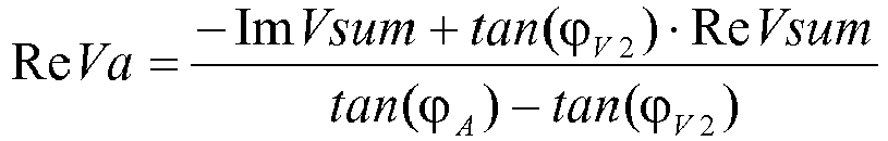
- Verfahren zum Schätzen eines Phasenwinkels einer Nullspannung nach Anspruch 9, dadurch gekennzeichnet, dass der Realteil und der Imaginärteil der A-Phasenspannung wie folgt sind:


- Vorrichtung zum Schätzen eines Phasenwinkels einer Nullspannung, wenn ein einphasiger Erdschluss in einem Verteilungsnetz auftritt, wobei das Verteilungsnetz eine A-Phase mit dem Erdschluss, eine B-Phase und eine C-Phase umfasst, wobei die Vorrichtung dadurch gekennzeichnet ist, dass sie umfasst:einen Winkeldetektor, der konfiguriert ist, um einen Phasenwinkel ϕ A einer A-Phasenspannung zu erfassen, einen Winkeldetektor, der konfiguriert ist, um einen Phasenwinkel ϕB einer B-Phasenspannung zu erfassen, und einen Winkeldetektor, der konfiguriert ist, um einen Phasenwinkel ϕ C einer C-Phasenspannung zu erfassen; undeinen Winkelschätzer, der konfiguriert ist, um eine Größe FB der B-Phasenspannung als vorbestimmten Referenzwert einzustellen, um die A-Phasenspannung und die C-Phasenspannung unter Verwendung der Größe der B-Phasenspannung, des Phasenwinkels ϕ A der A-Phasenspannung, des Phasenwinkels ϕB der B-Phasenspannung und des Phasenwinkels ϕ C der C-Phasenspannung basierend auf einem neutralen Erdungstyp des Verteilungsnetzes zu schätzen; und um den Phasenwinkel der Nullspannung unter Verwendung der B-Phasenspannung und der geschätzten A-Phasenspannung und der geschätzten C-Phasenspannung zu berechnen.
- Vorrichtung zum Schätzen eines Phasenwinkels einer Nullspannung nach Anspruch 11, wobei der Winkelschätzer konfiguriert ist, um in einem Fall, bei dem die neutrale Erdungsart des Verteilungsnetzes eine neutrale Resonanzerdung oder eine neutrale isolierte Erdung ist, Realteile und Imaginärteile der B-Phase, der C-Phase und der A-Phase durch folgende Gleichungen zu berechnen:


- Vorrichtung zum Schätzen eines Phasenwinkels einer Nullspannung nach Anspruch 11, die ferner einen A-Phasen-Stromwandler, einen B-Phasen-Stromwandler und einen C-Phasen-Stromwandler umfasst,
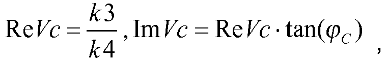
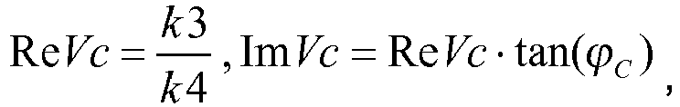
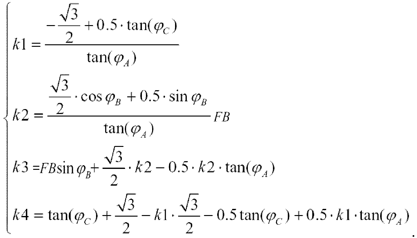
wobei der Winkelschätzer konfiguriert ist, um in einem Fall, bei dem die neutrale Erdungsart des Verteilungsnetzes eine neutrale feste Erdung ist, eine Größe FC der C-Phasenspannung als ein vorgegebenes Vielfaches der Größe FB der B-Phasenspannung zu bestimmen, einen Winkel einer Gegen-Impedanz an einer Erdschlussdetektionsvorrichtung zu schätzen, einen Winkel eines Gegen-Stroms gemäß drei Phasenströmen, die von dem A-Phasen-Stromwandler, dem B-Phasen-Stromwandler und dem C-Phasen-Stromwandler bereitgestellt werden, zu berechnen und den Realteil und den Imaginärteil der A-Phasenspannung gemäß den folgenden Gleichungen zu schätzen:

B + α · FC · ejϕC ,
- Vorrichtung zum Schätzen eines Phasenwinkels einer Nullspannung nach Anspruch 13, wobei der Winkel der Gegen-Impedanz an der Erdschlussdetektionsvorrichtung als erster vorgegebener Winkel geschätzt wird, in einem Fall, bei dem die Erdschlussdetektionsvorrichtung weit von der dezentralen Erzeugungsvorrichtung und den Lasten entfernt ist und sich auf einer Mittelspannungsseite im Verteilungsnetz befindet;
der Winkel der Gegen-Impedanz an der Erdschlussdetektionsvorrichtung als zweiter vorgegebener Winkel in einem Fall geschätzt wird, bei dem sich die Erdschlussdetektionsvorrichtung in der Nähe der dezentralen Erzeugungsvorrichtung befindet und sich auf einer Mittelspannungsseite im Verteilungsnetz befindet; und
der Winkel der Gegen-Impedanz an der Erdschlussdetektionsvorrichtung als dritter vorgegebener Winkel in einem Fall geschätzt wird, bei dem sich die Erdschlussdetektionsvorrichtung in der Nähe von Lasten befindet und sich auf einer Mittelspannungsseite im Verteilungsnetz befindet.
Applications Claiming Priority (1)
| Application Number | Priority Date | Filing Date | Title |
|---|---|---|---|
| CN201310314222.6A CN104345197B (zh) | 2013-07-24 | 2013-07-24 | 在单相接地故障时估计零序电压的角度的方法及设备 |
Publications (2)
| Publication Number | Publication Date |
|---|---|
| EP2829887A1 EP2829887A1 (de) | 2015-01-28 |
| EP2829887B1 true EP2829887B1 (de) | 2019-09-25 |
Family
ID=50933118
Family Applications (1)
| Application Number | Title | Priority Date | Filing Date |
|---|---|---|---|
| EP14305836.0A Active EP2829887B1 (de) | 2013-07-24 | 2014-06-03 | Verfahren und Vorrichtung zur Schätzung des Winkels der Spannung im Nullsystem bei einphasigem Erdschluss |
Country Status (5)
| Country | Link |
|---|---|
| EP (1) | EP2829887B1 (de) |
| CN (1) | CN104345197B (de) |
| BR (1) | BR102014016231A2 (de) |
| ES (1) | ES2755044T3 (de) |
| RU (1) | RU2571629C1 (de) |
Families Citing this family (27)
| Publication number | Priority date | Publication date | Assignee | Title |
|---|---|---|---|---|
| FI126434B (fi) * | 2015-06-03 | 2016-11-30 | Jyväskylän Energia Oy | Menetelmä kolmivaiheisen sähköverkon maasulkusuojauksessa |
| CN105589012B (zh) * | 2015-07-27 | 2018-08-03 | 中国计量学院 | 联网型微电网不对称故障区域检测装置及诊断方法 |
| CN105162086B (zh) * | 2015-09-11 | 2016-06-29 | 国家电网公司 | 针对dg并网变压器接地系统的保护方法 |
| CN105259467B (zh) * | 2015-11-18 | 2018-02-09 | 南京国电南自电网自动化有限公司 | 一种考虑星三角变换的单相故障分析方法 |
| CN105891670B (zh) * | 2016-03-30 | 2018-11-06 | 国网福建省电力有限公司 | 利用电压虚部方向特性实现线路相间故障单端定位方法 |
| SE539916C2 (sv) * | 2016-05-11 | 2018-01-16 | Dlaboratory Sweden Ab | Metod och anordning för bortkoppling av fel i elnät |
| CN107340449B (zh) * | 2017-06-16 | 2020-05-05 | 国网福建省电力有限公司 | 一种自适应混合接地方式的单相接地故障定位方法及系统 |
| KR20190128296A (ko) * | 2018-05-08 | 2019-11-18 | 엘에스산전 주식회사 | 표준값을 이용한 방향성 보호 계전기 및 그 제어방법 |
| CN109830942B (zh) * | 2018-06-19 | 2020-05-19 | 西安交通大学 | 基于电压突变量和三序分量不对称度闭锁反向合闸方法 |
| CN108646134B (zh) * | 2018-06-22 | 2020-10-09 | 中国长江电力股份有限公司 | 基于相量分析的发电机定子绕组单相接地故障定位方法 |
| DE102019105861A1 (de) * | 2019-03-07 | 2020-09-10 | Sma Solar Technology Ag | Verfahren und Vorrichtung zur näherungsweisen Bestimmung von Spannungen an einer Oberspannungsseite eines Transformators |
| CN110231546B (zh) * | 2019-07-19 | 2022-03-29 | 南方电网电力科技股份有限公司 | 一种配电网故障区段定位方法、装置及设备 |
| CN110504664B (zh) * | 2019-08-26 | 2021-04-27 | 燕山大学 | 含分布式电源的配电网自适应限时正序电流速断保护方法 |
| CN111817271B (zh) * | 2020-07-08 | 2022-06-07 | 国网福建省电力有限公司检修分公司 | 特高压交流输电线路单相接地电压幅值保护方法 |
| CN112881861B (zh) * | 2021-01-18 | 2022-07-29 | 长沙理工大学 | 一种配电网的故障定位方法及其系统 |
| CN113093060B (zh) * | 2021-04-13 | 2022-05-20 | 厦门理工学院 | 一种配电网的断零线检测方法、装置及设备 |
| CN113759182B (zh) * | 2021-08-26 | 2024-10-01 | 北京四方继保工程技术有限公司 | 利用非故障相电压判别不对称故障阻抗方向的方法及系统 |
| CN114113882B (zh) * | 2021-11-12 | 2022-11-01 | 国网山东省电力公司青岛供电公司 | 一种基于模糊计算的输电线路故障定位方法及系统 |
| CN114325468B (zh) * | 2021-12-01 | 2023-09-19 | 国网辽宁省电力有限公司锦州供电公司 | 利用66kV主动干预消弧装置进行接地选相选线的方法 |
| CN114764599B (zh) * | 2022-04-26 | 2023-06-09 | 国网四川省电力公司电力科学研究院 | 一种配电网单相接地故障灵敏度分析方法和系统 |
| CN116482480A (zh) * | 2023-04-26 | 2023-07-25 | 西安兴汇电力科技有限公司 | 一种中压配电网单相断线故障综合判别方法 |
| CN116930685B (zh) * | 2023-09-18 | 2023-12-05 | 青岛鼎信通讯科技有限公司 | 一种适用于配电网单相接地故障的单端测距方法 |
| CN119001326B (zh) * | 2024-08-15 | 2026-01-30 | 华北电力大学 | 基于暂态相电压的配电网单相接地故障选相方法和系统 |
| CN118731590B (zh) * | 2024-09-02 | 2024-11-12 | 国网陕西省电力有限公司电力科学研究院 | 一种有源配电网单相断线故障检测方法及相关装置 |
| CN119543070B (zh) * | 2024-11-20 | 2025-05-06 | 国网江苏省电力有限公司电力科学研究院 | 双端弱馈系统单相故障性质鉴别方法、装置、设备及介质 |
| CN119231531B (zh) * | 2024-12-05 | 2025-02-25 | 厦门理工学院 | 一种分布式电源与柔直变流器协同的电压支撑方法 |
| CN119846393A (zh) * | 2025-03-10 | 2025-04-18 | 华北电力大学 | 含dg的配电线路单相接地故障单端阻抗测距技术 |
Family Cites Families (14)
| Publication number | Priority date | Publication date | Assignee | Title |
|---|---|---|---|---|
| RU2097893C1 (ru) * | 1995-04-28 | 1997-11-27 | Александр Владимирович Малеев | Способ направленной защиты от однофазного замыкания на землю в электрической сети переменного тока и устройство для его осуществления |
| FI100922B (fi) * | 1996-11-04 | 1998-03-13 | Abb Transmit Oy | Menetelmä sähkönjakeluverkon suuriresistanssisen maasulkuvian havaitse miseksi ja paikallistamiseksi |
| FI103217B1 (fi) * | 1997-08-27 | 1999-05-14 | Abb Transmit Oy | Menetelmä sähkönjakeluverkon suuriresistanssisen maasulkuvian paikallistamiseksi virtamittausten perusteella |
| UA29534C2 (uk) * | 1999-04-02 | 2000-11-15 | Євген Віталійович Сергін | Спосіб визначення пошкодженої фази на землю в трифазній мережі з ізольованою нейтраллю |
| FI108168B (fi) * | 2000-03-27 | 2001-11-30 | Abb Substation Automation Oy | Menetelmä sähköverkon lähdön sähköisen eristystilan määrittämiseksi |
| FI108894B (fi) * | 2000-09-22 | 2002-04-15 | Abb Substation Automation Oy | Menetelmä sähköverkon vikaantumassa olevan tai viallisen lähdön tai haaran ilmaisemiseksi esimerkiksi kompensoidussa verkossa |
| US20030074146A1 (en) * | 2001-09-13 | 2003-04-17 | Stoupis James D. | Crossover fault classification for power lines with parallel circuits |
| FI115488B (fi) * | 2003-10-22 | 2005-05-13 | Abb Oy | Menetelmä ja laitteisto katkeilevan maasulun tunnistamiseksi sähkönjakeluverkossa |
| FI118492B (fi) * | 2005-05-17 | 2007-11-30 | Abb Oy | Järjestelmä ja menetelmä maasulkuvian sijainnin määrittämiseksi |
| CN100495055C (zh) * | 2007-06-14 | 2009-06-03 | 上海交通大学 | 检测发电机定子单相接地故障方向的方法 |
| HUP0700837A2 (en) * | 2007-12-21 | 2009-08-28 | Andras Dr Dan | Measuring system for localising and identifying a resistance of earth fault in active network and method for using the system |
| EP2192416B1 (de) * | 2008-11-26 | 2018-01-03 | ABB Schweiz AG | Verfahren und Vorrichtung zur Erkennung eines einpoligen Erdschlusses |
| CN102426316B (zh) * | 2011-08-25 | 2014-03-05 | 南京南瑞继保电气有限公司 | 一种发电机定子绕组单相接地故障定位方法 |
| CN103149502B (zh) * | 2013-02-20 | 2015-08-12 | 保定浪拜迪电气股份有限公司 | 基于同步采样装置的输电线路故障测距方法 |
-
2013
- 2013-07-24 CN CN201310314222.6A patent/CN104345197B/zh active Active
-
2014
- 2014-06-03 ES ES14305836T patent/ES2755044T3/es active Active
- 2014-06-03 EP EP14305836.0A patent/EP2829887B1/de active Active
- 2014-06-30 BR BR102014016231A patent/BR102014016231A2/pt not_active IP Right Cessation
- 2014-07-23 RU RU2014130592/07A patent/RU2571629C1/ru not_active IP Right Cessation
Non-Patent Citations (1)
| Title |
|---|
| None * |
Also Published As
| Publication number | Publication date |
|---|---|
| CN104345197B (zh) | 2017-09-15 |
| BR102014016231A2 (pt) | 2015-10-06 |
| CN104345197A (zh) | 2015-02-11 |
| RU2571629C1 (ru) | 2015-12-20 |
| EP2829887A1 (de) | 2015-01-28 |
| ES2755044T3 (es) | 2020-04-21 |
Similar Documents
| Publication | Publication Date | Title |
|---|---|---|
| EP2829887B1 (de) | Verfahren und Vorrichtung zur Schätzung des Winkels der Spannung im Nullsystem bei einphasigem Erdschluss | |
| US8866487B2 (en) | Directional fault sectionalizing system | |
| EP1982395B1 (de) | Verfahren und adaptives abstandsschutzrelais für stromübertragungsleitungen | |
| US20190245343A1 (en) | Method to detect utility disturbance and fault direction | |
| US10931097B2 (en) | Generator stator ground protection using third harmonic | |
| EP3776778B1 (de) | Verfahren und vorrichtung zum schutz in einem leistungsübertragungssystem mit mehreren endgeräten | |
| US20080150544A1 (en) | Multi-ended fault location system | |
| WO1998029752A1 (en) | System for locating faults and estimating fault resistance in distribution networks with tapped loads | |
| WO1998029752A9 (en) | System for locating faults and estimating fault resistance in distribution networks with tapped loads | |
| CN105811383A (zh) | 一种新型微电网正序阻抗差动保护方法 | |
| EP3369150B1 (de) | Verfahren und system zum schutz in einer gemischten leitung | |
| US10784677B2 (en) | Enhanced utility disturbance monitor | |
| US20210063460A1 (en) | Current-based directional element in a power delivery system | |
| Bretas et al. | Fault location in unbalanced DG systems using the positive sequence apparent impedance | |
| CN101593964A (zh) | 同杆并架双回线的纵联零序功率方向保护方法 | |
| Xu et al. | A new fault-impedance algorithm for distance relaying on a transmission line | |
| US11327105B2 (en) | Fault location in multi-terminal tapped lines | |
| CN104965151A (zh) | 一种基于故障点电压突变量的故障测距方法 | |
| WO2019166903A1 (en) | Method and device for fault location in a two-terminal transmission system | |
| RU2558266C1 (ru) | Способ определения расстояния до мест замыканий на землю на двух линиях электропередачи в сетях с малыми токами замыкания на землю | |
| CN115336130B (zh) | 电力传输系统中的故障检测 | |
| CN107656163B (zh) | 三相三线计量装置接线及接地自动检测仪器的测控方法 | |
| CN104953565B (zh) | 基于过渡电阻实测线路相间故障继电保护方法 | |
| CN107959276A (zh) | 一种单回线自适应重合闸方法 | |
| Voloh et al. | Fault locator based on line current differential relays synchronized measurements |
Legal Events
| Date | Code | Title | Description |
|---|---|---|---|
| 17P | Request for examination filed |
Effective date: 20140603 |
|
| AK | Designated contracting states |
Kind code of ref document: A1 Designated state(s): AL AT BE BG CH CY CZ DE DK EE ES FI FR GB GR HR HU IE IS IT LI LT LU LV MC MK MT NL NO PL PT RO RS SE SI SK SM TR |
|
| AX | Request for extension of the european patent |
Extension state: BA ME |
|
| PUAI | Public reference made under article 153(3) epc to a published international application that has entered the european phase |
Free format text: ORIGINAL CODE: 0009012 |
|
| R17P | Request for examination filed (corrected) |
Effective date: 20150728 |
|
| RBV | Designated contracting states (corrected) |
Designated state(s): AL AT BE BG CH CY CZ DE DK EE ES FI FR GB GR HR HU IE IS IT LI LT LU LV MC MK MT NL NO PL PT RO RS SE SI SK SM TR |
|
| GRAP | Despatch of communication of intention to grant a patent |
Free format text: ORIGINAL CODE: EPIDOSNIGR1 |
|
| STAA | Information on the status of an ep patent application or granted ep patent |
Free format text: STATUS: GRANT OF PATENT IS INTENDED |
|
| INTG | Intention to grant announced |
Effective date: 20190426 |
|
| GRAS | Grant fee paid |
Free format text: ORIGINAL CODE: EPIDOSNIGR3 |
|
| GRAA | (expected) grant |
Free format text: ORIGINAL CODE: 0009210 |
|
| STAA | Information on the status of an ep patent application or granted ep patent |
Free format text: STATUS: THE PATENT HAS BEEN GRANTED |
|
| AK | Designated contracting states |
Kind code of ref document: B1 Designated state(s): AL AT BE BG CH CY CZ DE DK EE ES FI FR GB GR HR HU IE IS IT LI LT LU LV MC MK MT NL NO PL PT RO RS SE SI SK SM TR |
|
| REG | Reference to a national code |
Ref country code: GB Ref legal event code: FG4D |
|
| REG | Reference to a national code |
Ref country code: CH Ref legal event code: EP |
|
| REG | Reference to a national code |
Ref country code: DE Ref legal event code: R096 Ref document number: 602014054153 Country of ref document: DE |
|
| REG | Reference to a national code |
Ref country code: AT Ref legal event code: REF Ref document number: 1184331 Country of ref document: AT Kind code of ref document: T Effective date: 20191015 |
|
| REG | Reference to a national code |
Ref country code: IE Ref legal event code: FG4D |
|
| REG | Reference to a national code |
Ref country code: NL Ref legal event code: MP Effective date: 20190925 |
|
| PG25 | Lapsed in a contracting state [announced via postgrant information from national office to epo] |
Ref country code: BG Free format text: LAPSE BECAUSE OF FAILURE TO SUBMIT A TRANSLATION OF THE DESCRIPTION OR TO PAY THE FEE WITHIN THE PRESCRIBED TIME-LIMIT Effective date: 20191225 Ref country code: NO Free format text: LAPSE BECAUSE OF FAILURE TO SUBMIT A TRANSLATION OF THE DESCRIPTION OR TO PAY THE FEE WITHIN THE PRESCRIBED TIME-LIMIT Effective date: 20191225 Ref country code: LT Free format text: LAPSE BECAUSE OF FAILURE TO SUBMIT A TRANSLATION OF THE DESCRIPTION OR TO PAY THE FEE WITHIN THE PRESCRIBED TIME-LIMIT Effective date: 20190925 Ref country code: FI Free format text: LAPSE BECAUSE OF FAILURE TO SUBMIT A TRANSLATION OF THE DESCRIPTION OR TO PAY THE FEE WITHIN THE PRESCRIBED TIME-LIMIT Effective date: 20190925 Ref country code: SE Free format text: LAPSE BECAUSE OF FAILURE TO SUBMIT A TRANSLATION OF THE DESCRIPTION OR TO PAY THE FEE WITHIN THE PRESCRIBED TIME-LIMIT Effective date: 20190925 Ref country code: HR Free format text: LAPSE BECAUSE OF FAILURE TO SUBMIT A TRANSLATION OF THE DESCRIPTION OR TO PAY THE FEE WITHIN THE PRESCRIBED TIME-LIMIT Effective date: 20190925 |
|
| REG | Reference to a national code |
Ref country code: LT Ref legal event code: MG4D |
|
| PG25 | Lapsed in a contracting state [announced via postgrant information from national office to epo] |
Ref country code: GR Free format text: LAPSE BECAUSE OF FAILURE TO SUBMIT A TRANSLATION OF THE DESCRIPTION OR TO PAY THE FEE WITHIN THE PRESCRIBED TIME-LIMIT Effective date: 20191226 Ref country code: LV Free format text: LAPSE BECAUSE OF FAILURE TO SUBMIT A TRANSLATION OF THE DESCRIPTION OR TO PAY THE FEE WITHIN THE PRESCRIBED TIME-LIMIT Effective date: 20190925 Ref country code: RS Free format text: LAPSE BECAUSE OF FAILURE TO SUBMIT A TRANSLATION OF THE DESCRIPTION OR TO PAY THE FEE WITHIN THE PRESCRIBED TIME-LIMIT Effective date: 20190925 |
|
| REG | Reference to a national code |
Ref country code: AT Ref legal event code: MK05 Ref document number: 1184331 Country of ref document: AT Kind code of ref document: T Effective date: 20190925 |
|
| REG | Reference to a national code |
Ref country code: ES Ref legal event code: FG2A Ref document number: 2755044 Country of ref document: ES Kind code of ref document: T3 Effective date: 20200421 |
|
| PG25 | Lapsed in a contracting state [announced via postgrant information from national office to epo] |
Ref country code: PT Free format text: LAPSE BECAUSE OF FAILURE TO SUBMIT A TRANSLATION OF THE DESCRIPTION OR TO PAY THE FEE WITHIN THE PRESCRIBED TIME-LIMIT Effective date: 20200127 Ref country code: IT Free format text: LAPSE BECAUSE OF FAILURE TO SUBMIT A TRANSLATION OF THE DESCRIPTION OR TO PAY THE FEE WITHIN THE PRESCRIBED TIME-LIMIT Effective date: 20190925 Ref country code: AL Free format text: LAPSE BECAUSE OF FAILURE TO SUBMIT A TRANSLATION OF THE DESCRIPTION OR TO PAY THE FEE WITHIN THE PRESCRIBED TIME-LIMIT Effective date: 20190925 Ref country code: NL Free format text: LAPSE BECAUSE OF FAILURE TO SUBMIT A TRANSLATION OF THE DESCRIPTION OR TO PAY THE FEE WITHIN THE PRESCRIBED TIME-LIMIT Effective date: 20190925 Ref country code: AT Free format text: LAPSE BECAUSE OF FAILURE TO SUBMIT A TRANSLATION OF THE DESCRIPTION OR TO PAY THE FEE WITHIN THE PRESCRIBED TIME-LIMIT Effective date: 20190925 Ref country code: EE Free format text: LAPSE BECAUSE OF FAILURE TO SUBMIT A TRANSLATION OF THE DESCRIPTION OR TO PAY THE FEE WITHIN THE PRESCRIBED TIME-LIMIT Effective date: 20190925 Ref country code: PL Free format text: LAPSE BECAUSE OF FAILURE TO SUBMIT A TRANSLATION OF THE DESCRIPTION OR TO PAY THE FEE WITHIN THE PRESCRIBED TIME-LIMIT Effective date: 20190925 Ref country code: RO Free format text: LAPSE BECAUSE OF FAILURE TO SUBMIT A TRANSLATION OF THE DESCRIPTION OR TO PAY THE FEE WITHIN THE PRESCRIBED TIME-LIMIT Effective date: 20190925 |
|
| PG25 | Lapsed in a contracting state [announced via postgrant information from national office to epo] |
Ref country code: IS Free format text: LAPSE BECAUSE OF FAILURE TO SUBMIT A TRANSLATION OF THE DESCRIPTION OR TO PAY THE FEE WITHIN THE PRESCRIBED TIME-LIMIT Effective date: 20200224 Ref country code: CZ Free format text: LAPSE BECAUSE OF FAILURE TO SUBMIT A TRANSLATION OF THE DESCRIPTION OR TO PAY THE FEE WITHIN THE PRESCRIBED TIME-LIMIT Effective date: 20190925 Ref country code: SM Free format text: LAPSE BECAUSE OF FAILURE TO SUBMIT A TRANSLATION OF THE DESCRIPTION OR TO PAY THE FEE WITHIN THE PRESCRIBED TIME-LIMIT Effective date: 20190925 Ref country code: SK Free format text: LAPSE BECAUSE OF FAILURE TO SUBMIT A TRANSLATION OF THE DESCRIPTION OR TO PAY THE FEE WITHIN THE PRESCRIBED TIME-LIMIT Effective date: 20190925 |
|
| REG | Reference to a national code |
Ref country code: DE Ref legal event code: R097 Ref document number: 602014054153 Country of ref document: DE |
|
| PG2D | Information on lapse in contracting state deleted |
Ref country code: IS |
|
| PG25 | Lapsed in a contracting state [announced via postgrant information from national office to epo] |
Ref country code: DK Free format text: LAPSE BECAUSE OF FAILURE TO SUBMIT A TRANSLATION OF THE DESCRIPTION OR TO PAY THE FEE WITHIN THE PRESCRIBED TIME-LIMIT Effective date: 20190925 Ref country code: IS Free format text: LAPSE BECAUSE OF FAILURE TO SUBMIT A TRANSLATION OF THE DESCRIPTION OR TO PAY THE FEE WITHIN THE PRESCRIBED TIME-LIMIT Effective date: 20200126 |
|
| PLBE | No opposition filed within time limit |
Free format text: ORIGINAL CODE: 0009261 |
|
| STAA | Information on the status of an ep patent application or granted ep patent |
Free format text: STATUS: NO OPPOSITION FILED WITHIN TIME LIMIT |
|
| 26N | No opposition filed |
Effective date: 20200626 |
|
| PG25 | Lapsed in a contracting state [announced via postgrant information from national office to epo] |
Ref country code: SI Free format text: LAPSE BECAUSE OF FAILURE TO SUBMIT A TRANSLATION OF THE DESCRIPTION OR TO PAY THE FEE WITHIN THE PRESCRIBED TIME-LIMIT Effective date: 20190925 |
|
| PG25 | Lapsed in a contracting state [announced via postgrant information from national office to epo] |
Ref country code: MC Free format text: LAPSE BECAUSE OF FAILURE TO SUBMIT A TRANSLATION OF THE DESCRIPTION OR TO PAY THE FEE WITHIN THE PRESCRIBED TIME-LIMIT Effective date: 20190925 |
|
| REG | Reference to a national code |
Ref country code: CH Ref legal event code: PL |
|
| PG25 | Lapsed in a contracting state [announced via postgrant information from national office to epo] |
Ref country code: LU Free format text: LAPSE BECAUSE OF NON-PAYMENT OF DUE FEES Effective date: 20200603 |
|
| REG | Reference to a national code |
Ref country code: BE Ref legal event code: MM Effective date: 20200630 |
|
| PG25 | Lapsed in a contracting state [announced via postgrant information from national office to epo] |
Ref country code: LI Free format text: LAPSE BECAUSE OF NON-PAYMENT OF DUE FEES Effective date: 20200630 Ref country code: IE Free format text: LAPSE BECAUSE OF NON-PAYMENT OF DUE FEES Effective date: 20200603 Ref country code: CH Free format text: LAPSE BECAUSE OF NON-PAYMENT OF DUE FEES Effective date: 20200630 |
|
| PG25 | Lapsed in a contracting state [announced via postgrant information from national office to epo] |
Ref country code: BE Free format text: LAPSE BECAUSE OF NON-PAYMENT OF DUE FEES Effective date: 20200630 |
|
| PG25 | Lapsed in a contracting state [announced via postgrant information from national office to epo] |
Ref country code: TR Free format text: LAPSE BECAUSE OF FAILURE TO SUBMIT A TRANSLATION OF THE DESCRIPTION OR TO PAY THE FEE WITHIN THE PRESCRIBED TIME-LIMIT Effective date: 20190925 Ref country code: MT Free format text: LAPSE BECAUSE OF FAILURE TO SUBMIT A TRANSLATION OF THE DESCRIPTION OR TO PAY THE FEE WITHIN THE PRESCRIBED TIME-LIMIT Effective date: 20190925 Ref country code: CY Free format text: LAPSE BECAUSE OF FAILURE TO SUBMIT A TRANSLATION OF THE DESCRIPTION OR TO PAY THE FEE WITHIN THE PRESCRIBED TIME-LIMIT Effective date: 20190925 |
|
| PG25 | Lapsed in a contracting state [announced via postgrant information from national office to epo] |
Ref country code: MK Free format text: LAPSE BECAUSE OF FAILURE TO SUBMIT A TRANSLATION OF THE DESCRIPTION OR TO PAY THE FEE WITHIN THE PRESCRIBED TIME-LIMIT Effective date: 20190925 |
|
| PGFP | Annual fee paid to national office [announced via postgrant information from national office to epo] |
Ref country code: DE Payment date: 20250626 Year of fee payment: 12 |
|
| PGFP | Annual fee paid to national office [announced via postgrant information from national office to epo] |
Ref country code: GB Payment date: 20250617 Year of fee payment: 12 |
|
| PGFP | Annual fee paid to national office [announced via postgrant information from national office to epo] |
Ref country code: FR Payment date: 20250624 Year of fee payment: 12 |
|
| PGFP | Annual fee paid to national office [announced via postgrant information from national office to epo] |
Ref country code: ES Payment date: 20250710 Year of fee payment: 12 |