EP2829870A1 - Method for determining composition of gas fuel, device for determining composition of gas fuel, fuel supply system, and fuel cell system - Google Patents
Method for determining composition of gas fuel, device for determining composition of gas fuel, fuel supply system, and fuel cell system Download PDFInfo
- Publication number
- EP2829870A1 EP2829870A1 EP13765236.8A EP13765236A EP2829870A1 EP 2829870 A1 EP2829870 A1 EP 2829870A1 EP 13765236 A EP13765236 A EP 13765236A EP 2829870 A1 EP2829870 A1 EP 2829870A1
- Authority
- EP
- European Patent Office
- Prior art keywords
- fuel
- composition
- gaseous fuel
- supply
- flow meter
- Prior art date
- Legal status (The legal status is an assumption and is not a legal conclusion. Google has not performed a legal analysis and makes no representation as to the accuracy of the status listed.)
- Withdrawn
Links
Images






Classifications
-
- H—ELECTRICITY
- H01—ELECTRIC ELEMENTS
- H01M—PROCESSES OR MEANS, e.g. BATTERIES, FOR THE DIRECT CONVERSION OF CHEMICAL ENERGY INTO ELECTRICAL ENERGY
- H01M8/00—Fuel cells; Manufacture thereof
- H01M8/04—Auxiliary arrangements, e.g. for control of pressure or for circulation of fluids
- H01M8/04298—Processes for controlling fuel cells or fuel cell systems
- H01M8/04313—Processes for controlling fuel cells or fuel cell systems characterised by the detection or assessment of variables; characterised by the detection or assessment of failure or abnormal function
-
- C—CHEMISTRY; METALLURGY
- C01—INORGANIC CHEMISTRY
- C01B—NON-METALLIC ELEMENTS; COMPOUNDS THEREOF; METALLOIDS OR COMPOUNDS THEREOF NOT COVERED BY SUBCLASS C01C
- C01B3/00—Hydrogen; Gaseous mixtures containing hydrogen; Separation of hydrogen from mixtures containing it; Purification of hydrogen; Reversible storage of hydrogen
- C01B3/02—Production of hydrogen; Production of gaseous mixtures containing hydrogen
- C01B3/32—Production of hydrogen; Production of gaseous mixtures containing hydrogen by reaction of gaseous or liquid organic compounds with gasifying agents, e.g. water, carbon dioxide or air
- C01B3/34—Production of hydrogen; Production of gaseous mixtures containing hydrogen by reaction of gaseous or liquid organic compounds with gasifying agents, e.g. water, carbon dioxide or air by reaction of hydrocarbons with gasifying agents
-
- G—PHYSICS
- G01—MEASURING; TESTING
- G01F—MEASURING VOLUME, VOLUME FLOW, MASS FLOW OR LIQUID LEVEL; METERING BY VOLUME
- G01F1/00—Measuring the volume flow or mass flow of fluid or fluent solid material wherein the fluid passes through a meter in a continuous flow
- G01F1/66—Measuring the volume flow or mass flow of fluid or fluent solid material wherein the fluid passes through a meter in a continuous flow by measuring frequency, phase shift or propagation time of electromagnetic or other waves, e.g. using ultrasonic flowmeters
-
- G—PHYSICS
- G01—MEASURING; TESTING
- G01N—INVESTIGATING OR ANALYSING MATERIALS BY DETERMINING THEIR CHEMICAL OR PHYSICAL PROPERTIES
- G01N29/00—Investigating or analysing materials by the use of ultrasonic, sonic or infrasonic waves; Visualisation of the interior of objects by transmitting ultrasonic or sonic waves through the object
- G01N29/02—Analysing fluids
- G01N29/024—Analysing fluids by measuring propagation velocity or propagation time of acoustic waves
-
- G—PHYSICS
- G05—CONTROLLING; REGULATING
- G05D—SYSTEMS FOR CONTROLLING OR REGULATING NON-ELECTRIC VARIABLES
- G05D7/00—Control of flow
- G05D7/06—Control of flow characterised by the use of electric means
- G05D7/0617—Control of flow characterised by the use of electric means specially adapted for fluid materials
-
- H—ELECTRICITY
- H01—ELECTRIC ELEMENTS
- H01M—PROCESSES OR MEANS, e.g. BATTERIES, FOR THE DIRECT CONVERSION OF CHEMICAL ENERGY INTO ELECTRICAL ENERGY
- H01M8/00—Fuel cells; Manufacture thereof
- H01M8/04—Auxiliary arrangements, e.g. for control of pressure or for circulation of fluids
- H01M8/04298—Processes for controlling fuel cells or fuel cell systems
- H01M8/04313—Processes for controlling fuel cells or fuel cell systems characterised by the detection or assessment of variables; characterised by the detection or assessment of failure or abnormal function
- H01M8/0432—Temperature; Ambient temperature
- H01M8/04328—Temperature; Ambient temperature of anode reactants at the inlet or inside the fuel cell
-
- H—ELECTRICITY
- H01—ELECTRIC ELEMENTS
- H01M—PROCESSES OR MEANS, e.g. BATTERIES, FOR THE DIRECT CONVERSION OF CHEMICAL ENERGY INTO ELECTRICAL ENERGY
- H01M8/00—Fuel cells; Manufacture thereof
- H01M8/04—Auxiliary arrangements, e.g. for control of pressure or for circulation of fluids
- H01M8/04298—Processes for controlling fuel cells or fuel cell systems
- H01M8/04313—Processes for controlling fuel cells or fuel cell systems characterised by the detection or assessment of variables; characterised by the detection or assessment of failure or abnormal function
- H01M8/0444—Concentration; Density
- H01M8/04447—Concentration; Density of anode reactants at the inlet or inside the fuel cell
-
- H—ELECTRICITY
- H01—ELECTRIC ELEMENTS
- H01M—PROCESSES OR MEANS, e.g. BATTERIES, FOR THE DIRECT CONVERSION OF CHEMICAL ENERGY INTO ELECTRICAL ENERGY
- H01M8/00—Fuel cells; Manufacture thereof
- H01M8/04—Auxiliary arrangements, e.g. for control of pressure or for circulation of fluids
- H01M8/04298—Processes for controlling fuel cells or fuel cell systems
- H01M8/04694—Processes for controlling fuel cells or fuel cell systems characterised by variables to be controlled
- H01M8/04746—Pressure; Flow
- H01M8/04753—Pressure; Flow of fuel cell reactants
-
- H—ELECTRICITY
- H01—ELECTRIC ELEMENTS
- H01M—PROCESSES OR MEANS, e.g. BATTERIES, FOR THE DIRECT CONVERSION OF CHEMICAL ENERGY INTO ELECTRICAL ENERGY
- H01M8/00—Fuel cells; Manufacture thereof
- H01M8/06—Combination of fuel cells with means for production of reactants or for treatment of residues
- H01M8/0606—Combination of fuel cells with means for production of reactants or for treatment of residues with means for production of gaseous reactants
- H01M8/0612—Combination of fuel cells with means for production of reactants or for treatment of residues with means for production of gaseous reactants from carbon-containing material
-
- H—ELECTRICITY
- H01—ELECTRIC ELEMENTS
- H01M—PROCESSES OR MEANS, e.g. BATTERIES, FOR THE DIRECT CONVERSION OF CHEMICAL ENERGY INTO ELECTRICAL ENERGY
- H01M8/00—Fuel cells; Manufacture thereof
- H01M8/06—Combination of fuel cells with means for production of reactants or for treatment of residues
- H01M8/0606—Combination of fuel cells with means for production of reactants or for treatment of residues with means for production of gaseous reactants
- H01M8/0612—Combination of fuel cells with means for production of reactants or for treatment of residues with means for production of gaseous reactants from carbon-containing material
- H01M8/0618—Reforming processes, e.g. autothermal, partial oxidation or steam reforming
-
- C—CHEMISTRY; METALLURGY
- C01—INORGANIC CHEMISTRY
- C01B—NON-METALLIC ELEMENTS; COMPOUNDS THEREOF; METALLOIDS OR COMPOUNDS THEREOF NOT COVERED BY SUBCLASS C01C
- C01B2203/00—Integrated processes for the production of hydrogen or synthesis gas
- C01B2203/02—Processes for making hydrogen or synthesis gas
- C01B2203/0205—Processes for making hydrogen or synthesis gas containing a reforming step
-
- C—CHEMISTRY; METALLURGY
- C01—INORGANIC CHEMISTRY
- C01B—NON-METALLIC ELEMENTS; COMPOUNDS THEREOF; METALLOIDS OR COMPOUNDS THEREOF NOT COVERED BY SUBCLASS C01C
- C01B2203/00—Integrated processes for the production of hydrogen or synthesis gas
- C01B2203/06—Integration with other chemical processes
- C01B2203/066—Integration with other chemical processes with fuel cells
-
- C—CHEMISTRY; METALLURGY
- C01—INORGANIC CHEMISTRY
- C01B—NON-METALLIC ELEMENTS; COMPOUNDS THEREOF; METALLOIDS OR COMPOUNDS THEREOF NOT COVERED BY SUBCLASS C01C
- C01B2203/00—Integrated processes for the production of hydrogen or synthesis gas
- C01B2203/12—Feeding the process for making hydrogen or synthesis gas
- C01B2203/1205—Composition of the feed
- C01B2203/1211—Organic compounds or organic mixtures used in the process for making hydrogen or synthesis gas
- C01B2203/1235—Hydrocarbons
- C01B2203/1241—Natural gas or methane
-
- C—CHEMISTRY; METALLURGY
- C01—INORGANIC CHEMISTRY
- C01B—NON-METALLIC ELEMENTS; COMPOUNDS THEREOF; METALLOIDS OR COMPOUNDS THEREOF NOT COVERED BY SUBCLASS C01C
- C01B2203/00—Integrated processes for the production of hydrogen or synthesis gas
- C01B2203/12—Feeding the process for making hydrogen or synthesis gas
- C01B2203/1205—Composition of the feed
- C01B2203/1211—Organic compounds or organic mixtures used in the process for making hydrogen or synthesis gas
- C01B2203/1235—Hydrocarbons
- C01B2203/1247—Higher hydrocarbons
-
- C—CHEMISTRY; METALLURGY
- C01—INORGANIC CHEMISTRY
- C01B—NON-METALLIC ELEMENTS; COMPOUNDS THEREOF; METALLOIDS OR COMPOUNDS THEREOF NOT COVERED BY SUBCLASS C01C
- C01B2203/00—Integrated processes for the production of hydrogen or synthesis gas
- C01B2203/16—Controlling the process
- C01B2203/169—Controlling the feed
-
- G—PHYSICS
- G01—MEASURING; TESTING
- G01N—INVESTIGATING OR ANALYSING MATERIALS BY DETERMINING THEIR CHEMICAL OR PHYSICAL PROPERTIES
- G01N2291/00—Indexing codes associated with group G01N29/00
- G01N2291/02—Indexing codes associated with the analysed material
- G01N2291/021—Gases
- G01N2291/0215—Mixtures of three or more gases, e.g. air
-
- G—PHYSICS
- G01—MEASURING; TESTING
- G01N—INVESTIGATING OR ANALYSING MATERIALS BY DETERMINING THEIR CHEMICAL OR PHYSICAL PROPERTIES
- G01N2291/00—Indexing codes associated with group G01N29/00
- G01N2291/02—Indexing codes associated with the analysed material
- G01N2291/021—Gases
- G01N2291/0217—Smoke, combustion gases
-
- G—PHYSICS
- G01—MEASURING; TESTING
- G01N—INVESTIGATING OR ANALYSING MATERIALS BY DETERMINING THEIR CHEMICAL OR PHYSICAL PROPERTIES
- G01N2291/00—Indexing codes associated with group G01N29/00
- G01N2291/02—Indexing codes associated with the analysed material
- G01N2291/028—Material parameters
- G01N2291/02818—Density, viscosity
-
- G—PHYSICS
- G01—MEASURING; TESTING
- G01N—INVESTIGATING OR ANALYSING MATERIALS BY DETERMINING THEIR CHEMICAL OR PHYSICAL PROPERTIES
- G01N2291/00—Indexing codes associated with group G01N29/00
- G01N2291/02—Indexing codes associated with the analysed material
- G01N2291/028—Material parameters
- G01N2291/02836—Flow rate, liquid level
-
- H—ELECTRICITY
- H01—ELECTRIC ELEMENTS
- H01M—PROCESSES OR MEANS, e.g. BATTERIES, FOR THE DIRECT CONVERSION OF CHEMICAL ENERGY INTO ELECTRICAL ENERGY
- H01M8/00—Fuel cells; Manufacture thereof
- H01M8/10—Fuel cells with solid electrolytes
- H01M8/12—Fuel cells with solid electrolytes operating at high temperature, e.g. with stabilised ZrO2 electrolyte
- H01M2008/1293—Fuel cells with solid oxide electrolytes
-
- Y—GENERAL TAGGING OF NEW TECHNOLOGICAL DEVELOPMENTS; GENERAL TAGGING OF CROSS-SECTIONAL TECHNOLOGIES SPANNING OVER SEVERAL SECTIONS OF THE IPC; TECHNICAL SUBJECTS COVERED BY FORMER USPC CROSS-REFERENCE ART COLLECTIONS [XRACs] AND DIGESTS
- Y02—TECHNOLOGIES OR APPLICATIONS FOR MITIGATION OR ADAPTATION AGAINST CLIMATE CHANGE
- Y02E—REDUCTION OF GREENHOUSE GAS [GHG] EMISSIONS, RELATED TO ENERGY GENERATION, TRANSMISSION OR DISTRIBUTION
- Y02E60/00—Enabling technologies; Technologies with a potential or indirect contribution to GHG emissions mitigation
- Y02E60/30—Hydrogen technology
- Y02E60/50—Fuel cells
Definitions
- the present invention relates to a method and a device for determining a composition of a hydrocarbon-based gaseous fuel supplied to a supply target by a fuel supply device, and a fuel supply system and a fuel cell system equipped with the composition determining device.
- Patent Document 1 to 3 As the related arts relating to the composition determination of the gaseous fuel, there are those described in Patent Document 1 to 3.
- the use of a speed of sound is disclosed. That is, the nitrogen concentration is estimated using the characteristic that the speed of sound of the fuel off-gas varies due to the difference in the ingredients of the fuel off-gas. It is understood that gas to be measured is a mixed gas of hydrogen and nitrogen.
- the speed of sound of the fuel off-gas is measured using the characteristic that the speed of sound is significantly fast in hydrogen, and the hydrogen concentration is obtained from the speed of sound.
- the composition of the gas to be measured is substantially defined by water, carbon dioxide, nitrogen and hydrogen.
- an effective composition of the gas is determined.
- the measurement target is a mixed gas of hydrogen and nitrogen in which the estimation of the composition is easy, and there is no description of gas in which hydrocarbons are complicatedly mixed therein.
- the measurement target is defined as a mixed gas of hydrogen, water, carbon dioxide, and nitrogen, and is limited thereto. Furthermore, in order to obtain a correlation, there is a need to measure or calculate the concentrations of water, carbon dioxide, nitrogen, or the like in the off-gas in advance.
- the plurality of hydrocarbon ingredients and hydrocarbons to be used as active ingredients have the same characteristics.
- the speed of sounds thereof are approximately the same (an error of about 0.3%), but when comparing the constant pressure specific heats thereof, there is an error of about 3%. Therefore, there may be the problem in the estimation accuracy.
- an object of the present invention is to provide a method and device for determining a composition capable of accurately performing composition determination of a hydrocarbon-based gaseous fuel, and to provide a fuel supply system and a fuel cell system equipped with the composition determining device.
- a method for determining a composition of a gaseous fuel according to the present invention includes the steps of: measuring a speed of sound in the gaseous fuel using an ultrasonic flow meter; estimating a carbon number of the gaseous fuel on the basis of the measured speed of sound; and estimating the composition of the gaseous fuel on the basis of the estimated carbon number.
- a device for determining a composition of a gaseous fuel including: a sound speed measuring unit configured to measure a speed of sound in the gaseous fuel using an ultrasonic flow meter; a carbon number estimating unit configured to estimate a carbon number of the gaseous fuel on the basis of the measured speed of sound; and a composition estimating unit configured to estimate the composition of the gaseous fuel on the basis of the estimated carbon number.
- a fuel supply system is a fuel supply system including a fuel supply device configured to supply a hydrocarbon-based gaseous fuel to a supply target, the fuel supply system including: the composition determining device; and a fuel supply amount control device configured to control a supply amount of fuel of the fuel supply device on the basis of the composition determined by the composition determining device.
- a fuel cell system including a fuel supply device configured to supply a hydrocarbon-based gaseous fuel, a fuel reforming device configured to generate a hydrogen-rich reformed fuel by reforming the supplied gaseous fuel, and a fuel cell stack configured to perform power generation by an electrochemical reaction between the generated reformed fuel and air, the fuel cell system including the composition determining device, and a fuel supply amount control unit configured to control a supply amount of fuel of the fuel supply device on the basis of the composition determined by the composition determining device.
- the present invention it is possible to relatively accurately estimate the composition of the gaseous fuel.
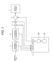
- Fig. 1 is a schematic configuration block diagram of the fuel supply system according to the first embodiment of the present invention.
- the fuel supply system of the present embodiment includes a fuel supply device 2 that supplies a hydrocarbon-based gaseous fuel to a supply target (various types of gas equipment) 1.
- the fuel supply device 2 is constituted by a pump and/or a flow control valve or the like connected to a gaseous fuel supply source, and a supply amount is controlled on the basis of a signal from a control device 7.
- a thermal flow meter (mass flow meter) 3 In a supply pathway to the supply target 1, through which the gaseous fuel is supplied by the fuel supply device 2, a thermal flow meter (mass flow meter) 3, an ultrasonic flow meter (volumetric flow meter) 4, a fuel temperature sensor 5, and a fuel pressure sensor 6 are provided on an upstream side (or a downstream side) of the fuel supply device 2.
- the components 3 to 6 may be arranged in any order.
- the thermal flow meter 3 measures a flow rate using a thermal diffusion effect of the gas, and since an amount of heat transmitted by the gas varies based on a compression degree of the gas, it is possible to measure a mass flow rate.
- the thermal flow meter 3 has characteristics in which the size reduction is easy and responsiveness is satisfactory due to the size reduction. However, since the output varies depending on the composition of the gas to be measured, it is common to use the thermal flow meter 3 with adjustment for the specified composition of the gas to be measured.
- the ultrasonic flow meter 4 is able to measure a volumetric flow rate without depending on the composition of the gas to be measured.
- the ultrasonic flow meter 4 is formed by disposing ultrasonic transceivers 4a and 4b each equipped with ultrasonic transducers on an upstream side and a downstream side in a flow direction to face each other, thereby measuring an arrival time t1 of the ultrasonic wave from upstream to downstream (forward direction), and an arrival time t2 of the ultrasonic wave from downstream to upstream (reverse direction).
- a diffusion speed in the forward direction is C + V
- a diffusion speed in the reverse direction is C - V.
- V 1 / t ⁇ 1 - 1 / t ⁇ 2 ⁇ L / 2
- C 1 / t ⁇ 1 + 1 / t ⁇ 2 ⁇ L / 2
- the ultrasonic flow meter 4 as a sound speed measuring unit for measuring the speed of sound in the gaseous fuel.
- the fuel temperature sensor 5 measures a fuel temperature Tf in the vicinity of the flow rate measuring portion.
- the fuel pressure sensor 6 measures a fuel pressure Pf in the vicinity of the flow rate measuring portion.
- Measurement signals of the thermal flow meter 3, the ultrasonic flow meter 4, the fuel temperature sensor 5, and the fuel pressure sensor 6 are sent to the control device 7.
- the control device 7 includes a microcomputer, performs the arithmetic processing in accordance with a control program, and controls the operation of the fuel supply device 2, while reading signals from various sensors, such as the thermal flow meter 3, the ultrasonic flow meter 4, the fuel temperature sensor 5, and the fuel pressure sensor 6.
- the control device 7 may control various other devices, simultaneously with the control of the fuel supply device 2.
- control device 7 Next, the control of a supply amount of fuel performed by the control device 7 will be described.
- a conversion factor of the thermal flow meter 3 is set on the basis of the specified composition, and then, the supply amount of fuel is controlled using the thermal flow meter 3. That is, a target supply amount of fuel is set according to target supply conditions, and the supply amount of gaseous fuel is controlled via the fuel supply device 2.
- feedback control is performed referring to the measured flow rate of the thermal flow meter 3.
- the supply amount of fuel is controlled using the ultrasonic flow meter 4 and thermal flow meter 3, while performing the composition determination.
- control device 7 is equipped with a composition determining unit (composition determining device) 100 configured to determine the composition of the hydrocarbon-based gaseous fuel supplied to the supply target 1 by the fuel supply device 2 in cooperation with the ultrasonic flow meter 4, and a fuel supply amount control unit 200 configured to control the supply amount of fuel of the fuel supply device 2 on the basis of the composition determined by the composition determining unit 100.
- composition determining device composition determining device
- fuel supply amount control unit 200 configured to control the supply amount of fuel of the fuel supply device 2 on the basis of the composition determined by the composition determining unit 100.
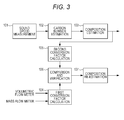
- the composition determining unit (composition determining device) 100 includes a sound speed measuring unit 101 configured to measure the speed of sound in the gaseous fuel using the ultrasonic flow meter 4, a carbon number estimating unit 102 configured to estimate a carbon number of the gaseous fuel on the basis of the measured speed of sound, and a composition estimating unit 103 configured to estimate the composition (ingredients and ingredient concentration) of the gaseous fuel on the basis of the estimated carbon number.
- the carbon number estimating unit 102 estimates the carbon number from a temperature and the speed of sound, using a table or a function of the carbon number with respect to the speed of sound at each temperature for the CH-based gas as illustrated in Fig. 4 .
- the composition estimating unit 103 specifies a sub-ingredient from predetermined sub-ingredient candidates, depending on the comparison result between the estimated carbon number and a carbon number previously determined for a main ingredient of the gaseous fuel, and estimates concentrations of the main ingredient and the specified sub-ingredient.
- the composition determining unit (composition determining device) 100 includes a first conversion factor calculating unit 104 configured to calculate a conversion factor of the mass flow meter on the basis of the measurement results of the mass flow meter (thermal flow meter 3) and the volumetric flow meter (ultrasonic flow meter 4), a second conversion factor calculating unit 105 configured to calculate an estimated conversion factor in the composition estimated by the composition estimating unit 103, and a comparison-and-verification unit 106 configured to compare and verify the estimation results of the composition estimating unit 103 by comparing the calculation results of the first and second conversion factor calculating units 104 and 105.
- composition determining unit (composition determining device) 100 includes a composition re-estimating unit 107 that estimates the composition of gaseous fuel again, assuming that another ingredient is mixed in the gaseous fuel when the comparison-and-verification unit 106 determines that there is a mismatch.
- the fuel supply amount control unit 200 in the control device 7 estimates a calorific value of the gaseous fuel on the basis of the composition determined by the composition determining unit (composition determining device) 100, and controls the supply amount of gaseous fuel so that the calorific value per unit time becomes a predetermined value.
- composition determining unit (composition determining device) 100 (101 to 107) is achieved by the flowcharts of Figs. 5 to 7
- function of the fuel supply amount control unit 200 is achieved by the flowchart of Fig. 8 .
- Figs. 5 to 7 are flowcharts of the composition determination of the gaseous fuel.
- a speed of sound C of the gaseous fuel is measured on the basis of the intermediate output of the ultrasonic flow meter 4.
- a volumetric flow rate Qv of the gaseous fuel is measured on the basis of the output of the ultrasonic flow meter 4.
- a temperature Tf of the gaseous fuel is measured on the basis of the output of the fuel temperature sensor 5.
- a pressure Pf of the gaseous fuel is measured on the basis of the output of the fuel pressure sensor 6.
- Conversion factor CF [Qv ⁇ (273.15 ⁇ (273.15 + Tf)) ⁇ ((101.33 + Pf) ⁇ 101.33)]/[Qm ⁇ ⁇ ]
- a denominator [Qm ⁇ y] of the calculation formula of the conversion factor CF is obtained by converting the mass flow rate Qm, the measured value of the thermal flow meter 3, into a normal flow rate (volumetric flow rate in the standard state). That is, it is obtained by dividing the mass flow rate Qm by the specific gravity ⁇ (specific gravity at the standard state of the design gas composition) and converting the divided value into the volumetric flow rate Q1 (see the following formula) at the standard state.
- Q ⁇ 1 Qm ⁇ ⁇
- a numerator of the calculation formula of the conversion factor CF is obtained by converting the volumetric flow rate Qv, the measured value of the ultrasonic flow meter 4, into a normal value. That is, the numerator is obtained by converting the volumetric flow rate Qv into a flow rate Q2 (see the following formula) at the standard (normal) state, using the fuel temperature Tf and the fuel pressure Pf.
- Q ⁇ 2 Qv ⁇ 273.15 ⁇ 273.15 + Tf ⁇ 101.33 + Pf ⁇ 101.33
- a carbon number of the gaseous fuel is estimated from the speed of sound C of the gaseous fuel.
- Fig. 4 illustrates the relationship between the speed of sound and the carbon number for the CH-based gas in terms of the temperature. That is, a solid line indicates the relationship between the speed of sound and the carbon number at a temperature T1 (for example, -10°C), and a dotted line indicates the relationship between the speed of sound and the carbon number at a temperature T2 (for example, 60°C).
- T1 for example, -10°C
- T2 for example, 60°C
- a carbon number (CN1) at the temperature T1 is obtained from the speed of sound C of the gaseous fuel with reference to the characteristics of the solid line of Fig. 4 .
- a carbon number (CN2) at the temperature T2 is obtained from the speed of sound C of the gaseous fuel with reference to the characteristics of the dotted line of Fig. 4 .
- a carbon number CN at the temperature Tf (current actual temperature) is obtained on the basis of the carbon number (CN1) at temperature T1 and the carbon number (CN2) at the temperature T2, by interpolation.
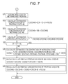
- CN ⁇ 1 the process proceeds to S11 in the flow of Fig. 6 , and it is assumed that the sub-ingredient is hydrogen and the gaseous fuel is a mixed gas of methane and hydrogen.
- the process proceeds to S21 in the flow of Fig. 7 , and it is assumed that the sub-ingredient is propane and the gaseous fuel is a mixed gas of methane and propane.
- the gaseous fuel is a mixed gas of methane CH4 (carbon number is 1) and hydrogen H2 (carbon number is 0).
- an estimated methane concentration CS(CH4) is calculated from the carbon number CN on the basis of the above-described assumption (see the following formula).
- CS CH ⁇ 4 CN ⁇ 100 %
- an estimated hydrogen concentration CS(H2) is calculated from the estimated methane concentration CS(CH4) (see the following formula).
- CS H ⁇ 2 100 - CS CH ⁇ 4
- an estimated conversion factor CF' of the gaseous fuel is calculated from the estimated methane concentration CS(CH4) and the estimated hydrogen concentration CS(H2), using the conversion factor CF(CH4) of methane CH4 and the conversion factor CF(H2) of hydrogen H2 (see the following formula).
- CF ⁇ 1 / CS CH ⁇ 4 / CF CH ⁇ 4 + CS H ⁇ 2 / CF H ⁇ 2
- conversion factor 1 / ⁇ volumetric fraction of ingredient i / conversion factor of ingredient i
- the conversion factor CF obtained in S6 is compared to the estimated conversion factor CF' obtained in S14 to determine whether the conversion factors match or do not match. Specifically, it is determined whether the difference between the conversion factors is less than a predetermined slice level SL (CF - CF' ⁇ SL). The reason is to verify the composition estimation in S12 and S13 by comparing them.
- the gaseous fuel is considered to be a mixed gas of methane CH4, hydrogen H2 and nitrogen N2, and the recalculation is performed in S16 to S18. That is, when the result of comparison and verification indicates a mismatch, it is assumed that another ingredient (nitrogen N2) be mixed in the gaseous fuel, and the composition of the gaseous fuel is estimated again.
- an estimated nitrogen concentration CS(N2) is calculated by the following formula.
- CS N ⁇ 2 A / B ⁇ 100 %
- A 1 / CF - CS CH ⁇ 4 / CF CH ⁇ 4 + CS H ⁇ 2 / CF H ⁇ 2 ⁇ 100
- B 1 / CF N ⁇ 2 - CS CH ⁇ 4 ⁇ ⁇ / CF CH ⁇ 4 + CS H ⁇ 2 ⁇ ⁇ / CF H ⁇ 2 ⁇ 100
- CF is the conversion factor
- CS(CH4) is the estimated methane concentration
- CF(CH4) is the conversion factor of methane
- CS(H2) is the estimated hydrogen concentration
- CF(H2) is the conversion factor of hydrogen.
- CF(N2) is a conversion factor of nitrogen
- CS(CH4)' is a methane concentration in a nitrogen-equivalent gas
- CF(CH4) is the conversion factor of methane
- CS(H2)' is a hydrogen concentration in the nitrogen-equivalent gas
- CF(H2) is the conversion factor of hydrogen.
- the methane concentration in the nitrogen-equivalent gas is a methane concentration X (%) in a gas of methane and hydrogen at a predetermined mixing ratio, the speed of sound of which is the same as that of nitrogen, and this methane concentration can be obtained by calculation in advance.
- the estimated methane concentration CS(CH4) is calculated again by the following formula.
- CS CH ⁇ 4 CS CH ⁇ 4 - CS N ⁇ 2 ⁇ CS CH ⁇ 4 ⁇ ⁇ ⁇ 100 %
- CS(CH4) is the estimated methane concentration (calculated in S12)
- CS(N2) is the estimated nitrogen concentration
- CS(CH4)' is the methane concentration in the nitrogen-equivalent gas.
- the estimated hydrogen concentration CS(H2) is calculated again by the following formula.
- CS H ⁇ 2 CS H ⁇ 2 - CS N ⁇ 2 ⁇ CS H ⁇ 2 ⁇ ⁇ ⁇ 100 %
- CS(H2) is the estimated hydrogen concentration (calculated in S13)
- CS(N2) is the estimated nitrogen concentration
- CS(H2)' is the hydrogen concentration in the nitrogen-equivalent gas.
- gaseous fuel is a mixed gas of methane CH4 (carbon number is 1) and propane C3H8 (carbon number is 3).
- an estimated propane concentration CS(C3H8) is calculated from the carbon number CN, on the basis of the assumption (see the following formula).
- CS C ⁇ 3 ⁇ H ⁇ 8 CN - 1 ⁇ 2 ⁇ 100 %
- an estimated methane concentration CS(CH4) is calculated from the estimated propane concentration CS(C3H8) (see the following formula).
- CS CH ⁇ 4 100 - CS C ⁇ 3 ⁇ H ⁇ 8
- an estimated conversion factor CF' of the gaseous fuel is calculated from the estimated methane concentration CS(CH4) and the estimated propane concentration CS(C3H8), using the conversion factor CF(CH4) of methane CH4 and the conversion factor CF(C3H8) of propane C3H8 (see the following formula).
- CF ⁇ 1 / CS CH ⁇ 4 / CF CH ⁇ 4 + CS C ⁇ 3 ⁇ H ⁇ 8 / CF C ⁇ 3 ⁇ H ⁇ 8
- the conversion factor CF obtained in S6 is compared to the estimated conversion factor CF' obtained in S24 to determine whether the conversion factors match or do not match. Specifically, it is determined whether the difference between the conversion factors is less than the predetermined slice level SL (CF - CF' ⁇ SL). The reason is to verify the composition estimation in S22 and S23 by comparing them.
- the gaseous fuel is considered to be a mixed gas of methane CH4, propane C3H8 and nitrogen N2, and the recalculation is performed in S26 to S28. That is, when the result of comparison and verification indicates a mismatch, it is considered that another ingredient (nitrogen N2) be mixed in the gaseous fuel, and the composition of the gaseous fuel is estimated again.
- an estimated nitrogen concentration CS(N2) is calculated by the following formula.
- CS N ⁇ 2 A / B ⁇ 100 %
- A 1 / CF - CS CH ⁇ 4 / CF CH ⁇ 4 + CS C ⁇ 3 ⁇ H ⁇ 8 / CF C ⁇ 3 ⁇ H ⁇ 8 ⁇ 100
- B 1 / CF N ⁇ 2 - CS CH ⁇ 4 ⁇ ⁇ / CF CH ⁇ 4 + CS C ⁇ 3 ⁇ H ⁇ 8 ⁇ ⁇ / CF C ⁇ 3 ⁇ H ⁇ 8 ⁇ 100
- CF is the conversion factor
- CS(CH4) is the estimated methane concentration
- CF(CH4) is the conversion factor of methane
- CS(C3H8) is the estimated propane concentration
- CF(C3H8) is the conversion factor of propane.
- CF(N2) is a conversion factor of nitrogen
- CS(CH4)' is a methane concentration in a nitrogen-equivalent gas
- CF(CH4) is the conversion factor of methane
- CS(C3H8)' is a propane concentration in the nitrogen-equivalent gas
- CF(C3H8) is the conversion factor of propane.
- the methane concentration in the nitrogen-equivalent gas is a methane concentration X' (%) in a gas of methane and propane at a predetermined mixing ratio, the speed of sound of which is the same as that of nitrogen, and this methane concentration can be obtained by calculation in advance.
- the estimated methane concentration CS(CH4) is calculated again by the following formula.
- CS CH ⁇ 4 CS CH ⁇ 4 - CS N ⁇ 2 ⁇ CS CH ⁇ 4 ⁇ ⁇ ⁇ 100 %
- CS(CH4) is the estimated methane concentration (calculated in S22)
- CS(N2) is the estimated nitrogen concentration
- CS(CH4)' is the methane concentration in the nitrogen-equivalent gas.
- the estimated propane concentration CS(C3H8) is calculated again by the following formula.
- CS C ⁇ 3 ⁇ H ⁇ 8 CS ( C ⁇ 3 ⁇ H ⁇ 8 - CS N ⁇ 2 ⁇ CS C ⁇ 3 ⁇ H ⁇ 8 ⁇ ⁇ ⁇ 100 %
- CS(C3H8) is the estimated propane concentration (calculated in S23)
- CS(N2) is the estimated nitrogen concentration
- CS(C3H8)' is the propane concentration in the nitrogen-equivalent gas.
- Fig. 8 is a flowchart of the fuel supply amount control based on the composition determination.
- a calorific value of the gaseous fuel (calorific value that occurs when fuel of a certain unit is completely combusted) is calculated.
- the calorific value of the gaseous fuel is calculated from each of the previously prepared known calorific values H(CH4), H(H2) and H(C3H8) of CH4, H2 and C3H8, and the concentration of each ingredients CS(CH4), CS(H2) and CS(C3H8) of CH4, H2 and C3H8, obtained in the flow of Figs. 5 to 7 , by the following formula.
- Calorific value of fuel CS CH ⁇ 4 ⁇ H CH ⁇ 4 + CS H ⁇ 2 ⁇ H H ⁇ 2 + CS C ⁇ 3 ⁇ H ⁇ 8 ⁇ H C ⁇ 3 ⁇ H ⁇ 8 / 100
- the supply amount of fuel calculated in this way is set to a control target value, and the supply amount of fuel is controlled via the fuel supply device 2.
- the device since the device includes the sound speed measuring unit 101 configured to measure the speed of sound in the gaseous fuel using the ultrasonic flow meter 4, the carbon number estimating unit 102 configured to estimate the carbon number of the gaseous fuel on the basis of the measured speed of sound, and the composition estimating unit 103 configured to estimate the composition (ingredients and ingredient concentration) of the gaseous fuel on the basis of the estimated carbon number, it is possible to relatively accurately estimate the composition of the gaseous fuel, and in particular, it is also possible to estimate the composition of gaseous fuel in which hydrocarbons are complicatedly mixed therein.
- the carbon number estimating unit 102 estimates the carbon number from the temperature and the speed of sound on the basis of the characteristic of the carbon number with respect to the speed of sound at each temperature (specifically, using the table or function), it is possible to easily and accurately estimate the carbon number.
- composition estimating unit 103 since the composition estimating unit 103 specifies the sub-ingredient from the predetermined sub-ingredient candidates (H2, C3H8) depending on the result of comparison between the estimated carbon number and the carbon number (1) previously determined for the main ingredient (CH4) of the gaseous fuel, and the composition estimating unit 103 estimates the concentrations of the main ingredient (CH4) and the specified sub-ingredient (H2 or C3H8), it is possible to perform the relatively simple estimation.
- the device since the device includes the mass flow meter (thermal flow meter 3) configured to measure the mass flow rate of the gaseous fuel supplied by the fuel supply device 2, the volumetric flow meter (ultrasonic flow meter 4) configured to measure the volumetric flow rate of the gaseous fuel supplied by the fuel supply device 2, the first conversion factor calculating unit 104 configured to calculate a conversion factor CF of the mass flow meter on the basis of the measurement results of the mass flow meter and the volumetric flow meter, the second conversion factor calculating unit 105 configured to calculate the estimated conversion factor CF' in the composition estimated by the composition estimating unit 103, and the comparison-and-verification unit 106 configured to compare and verify the estimation results of the composition estimating unit 103 by comparing the calculation results of the first and second conversion factor calculating units 104 and 105, it is possible to improve reliability of the estimation.
- the mass flow meter thermo flow meter 3
- the volumetric flow meter ultrasonic flow meter 4
- the first conversion factor calculating unit 104 configured to calculate
- the volumetric flow meter is the ultrasonic flow meter 4
- the sound speed measuring unit 101 measures the speed of sound in the gaseous fuel on the basis of the intermediate output of the ultrasonic flow meter 4, it is possible to reduce an increase in cost.
- the device since the device includes the composition re-estimating unit 107 that estimates the composition of gaseous fuel again assuming that another ingredient (N2) is mixed in the gaseous fuel when the comparison-and-verification unit 106 determines that there is a mismatch, it is possible to further improve the reliability of the estimation.
- the fuel supply amount control unit 200 configured to control the supply amount of fuel of the fuel supply device 2 on the basis of the composition determined by the composition determining unit 100, it is possible to appropriately reflect a variation in composition of the gaseous fuel in the control of the supply amount of fuel.
- the fuel supply amount control unit 200 estimates the calorific value of gaseous fuel on the basis of the composition estimated by the composition estimating unit 103, and controls the supply amount of gaseous fuel so that the calorific value per unit time becomes the predetermined value, it is possible to perform the appropriate control on the basis of the composition estimation of the gaseous fuel and it is possible to maintain the constant supply calorific value per unit time, even when the composition of the gaseous fuel varies. In other words, it is possible to control the supply amount of gaseous fuel by taking the calorific value as the management value.
- the supply target (gas equipment) of the fuel supply system was not described, the supply target is not particularly limited and may be used as a general-purpose fuel supply system.
- the applications thereof may include the combustion application requiring the control of the air-fuel ratio, and the chemical reaction application requiring the grasp of the raw material composition.
- Individual examples of combustion applications may include a boiler and a gas engine.
- the gas engine is used for a household cogeneration system (a system, in which a gas engine fueled by city gas or LPG performs power generation, and heat generated thereby is used to supply hot water; common name "ECOWILL (R)"), a GHP system (an air conditioning system that drives a compressor by a gas engine and performs cooling and heating by a heat-pump operation), an industrial private power generation system, or the like.
- ECOWILL a GHP system
- Individual examples of the chemical reaction applications may include a synthetic gas manufacturing device.
- the synthetic gas manufacturing device uses natural gas, LPG or the like as a raw material, and produces the synthetic gas mainly containing H2 and CO, using various reforming methods.
- the produced synthetic gas is used as a raw material gas for ammonia synthesis, methanol synthesis or the like. Recently, a demand for synthetic gas in association with new energy production such as GTL, DME, or SNG has been focused.
- Fig. 9 is a schematic configuration diagram of the fuel cell system according to the second embodiment of the present invention.
- the fuel cell system of the present embodiment includes a fuel reforming device 11 configured to generate a reformed hydrogen-rich fuel by performing the steam reforming of the hydrocarbon-based gaseous fuel, and a fuel cell stack (assembly of fuel cells) 12 configured to generate electricity by electrochemical reaction between the reformed fuel (hydrogen) from the fuel reforming device 11 and air (oxygen).
- a fuel reforming device 11 configured to generate a reformed hydrogen-rich fuel by performing the steam reforming of the hydrocarbon-based gaseous fuel
- a fuel cell stack (assembly of fuel cells) 12 configured to generate electricity by electrochemical reaction between the reformed fuel (hydrogen) from the fuel reforming device 11 and air (oxygen).
- the gaseous fuel from the gaseous fuel supply source is subjected to desulfurization removing sulfur compounds in the gaseous fuel by a desulfurizer 13, and then the gaseous fuel is supplied to the fuel reforming device 11 by a fuel supply device 14.
- the fuel supply device 14 is constituted by a pump and/or a flow rate control valve or the like, and a supply amount of gaseous fuel is controlled based on a signal from a control device 21.
- a thermal flow meter (mass flow meter) 15 In the supply pathway to the fuel reforming device 11, through which the gaseous fuel is supplied by the fuel supply device 14, a thermal flow meter (mass flow meter) 15, an ultrasonic flow meter 16, a fuel temperature sensor 17, and a fuel pressure sensor 18 are provided on an upstream side (or a downstream side) of the fuel supply device 14.
- the components 15 to 18 may be arranged in any order.
- the thermal flow meter 15, the ultrasonic flow meter 16, the fuel temperature sensor 17, and the fuel pressure sensor 18 are the same as the thermal flow meter 3, the ultrasonic flow meter 4, the fuel temperature sensor 5, and the fuel pressure sensor 6 of the first embodiment ( Fig. 1 ), respectively, the description thereof will not be provided.
- Measurement signals of the thermal flow meter 15, the ultrasonic flow meter 16, the fuel temperature sensor 17, and the fuel pressure sensor 18 are sent to the control device 21.
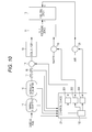
- the desulfurizer 13 is disposed on the upstream side of the fuel supply device 14, the thermal flow meter 15, the ultrasonic flow meter 16, the fuel temperature sensor 17, and the fuel pressure sensor 18, the desulfurizer 13 may be disposed on the downstream side of the fuel supply device 14, the thermal flow meter 15, the ultrasonic flow meter 16, the fuel temperature sensor 17, and the fuel pressure sensor 18, as illustrated in Fig. 10 .
- the arrangement of Fig. 9 is preferable to satisfactorily perform the supply control and the measurement of gaseous fuel even when the gaseous fuel is adsorbed to the desulfurizer 13. Therefore, for a low-temperature adsorption type desulfurizer, the arrangement of Fig. 9 may be adopted.
- the for-reforming water for performing the steam reforming in the fuel reforming device 11 is supplied by a for-reforming water supply device 19.
- the for-reforming water supply device 19 is constituted by a pump and/or a flow rate control valve or the like connected to a water supply source, and the supply amount of for-reforming water is controlled based on a signal from the control device 21.
- the reformed fuel from the fuel reforming device 11 is supplied to an anode (A) of the fuel cell stack 12, and air is supplied to a cathode (C) thereof.
- the cathode air is supplied by a cathode air supply device 20.
- the cathode air supply device 20 is constituted by a pump (blower) and/or a flow rate control valve or the like connected to the air supply source, and the supply amount is controlled based on a signal from the control device 21.
- the control device 21 includes a microcomputer, performs the arithmetic processing in accordance with a control program, and controls the operation of various types of equipment, such as the fuel supply device 14, the for-reforming water supply device 19, and the cathode air supply device 20, while reading signals from various sensors, such as the thermal flow meter 15, the ultrasonic flow meter 16, the fuel temperature sensor 17, and the fuel pressure sensor 18.
- the electrode reaction of Formula (7) described below occurs at the cathode of each cell, and the electrode reaction of Formula (8) described below occurs at the anode, thereby performing the power generation.
- Cathode 1 / 2 ⁇ O 2 + 2 ⁇ e - ⁇ O 2 - solid electrolyte
- Anode O 2 - solid electrolyte + H 2 ⁇ H 2 ⁇ O + 2 ⁇ e -
- control of fuel, the for-reforming water, and the cathode air using the control device 21 will be described.
- the supply amount of fuel is controlled using the thermal flow meter 15 after setting the conversion factor of the thermal flow meter 15 on the basis of the specified composition. That is, a supply amount of fuel (target value) is set in accordance with a target power generation conditions, and a supply amount of gaseous fuel is controlled via the fuel supply device 14. At this time, feedback control is performed, referring to the measured flow rate of the thermal flow meter 15. Furthermore, a supply amount of for-reforming water (target value) is set, referring to the measured flow rate of the thermal flow meter 15, for example, and a supply amount of for-reforming water is controlled via the for-reforming water supply device 19.
- a supply amount of cathode air (target value) is set, according to the target power generation condition or referring to the measured flow rate of the thermal flow meter 15, for example, and a supply amount of cathode air is controlled via the cathode air supply device 20.
- the supply amount of fuel, the supply amount of for-reforming water, and the supply amount of cathode air are controlled using the ultrasonic flow meter 16 and the thermal flow meter 15, while performing the composition determination.
- the control device 21 is equipped with a composition determining unit (composition determining device) 100 configured to determine the composition of the hydrocarbon-based gaseous fuel supplied to the fuel reforming device 11 by the fuel supply device 14 in cooperation with the ultrasonic flow meter 16, a fuel supply amount control unit 201 configured to control the supply amount of fuel of the fuel supply device 2 on the basis of the composition determined by the composition determining unit 100, a for-reforming water supply amount control unit 202 configured to control the supply amount of for-reforming water of the for-reforming water supply device 19, and a cathode air supply amount control unit 203 configured to control the supply amount of cathode air of the cathode air supply device 20.
- a composition determining unit (composition determining device) 100 configured to determine the composition of the hydrocarbon-based gaseous fuel supplied to the fuel reforming device 11 by the fuel supply device 14 in cooperation with the ultrasonic flow meter 16
- a fuel supply amount control unit 201 configured to control the supply amount of fuel of the fuel supply device 2 on the
- the composition determining unit 100 is the same as the composition determining unit 100 described in the first embodiment, and is configured as illustrated in the functional block diagram of Fig. 3 to perform the arithmetic processing in accordance with the flowcharts of Figs. 5 to 7 . Therefore, the description thereof will not be provided here.
- the fuel supply amount control unit 201 calculates, for example, quadruple values of the equivalent of the oxygen molecules capable of reacting at the time of complete combustion of the gaseous fuel, and calculates a supply amount of fuel on the basis of the quadruple values, the sweep DC current, and the fuel utilization rate.
- the for-reforming water supply amount control unit 202 calculates, for example, the carbon number of gaseous fuel on the basis of the composition of gaseous fuel estimated by the composition determining unit 100, and calculates the supply amount of for-reforming water on the basis of the carbon number.
- the supply amount of for-reforming water (target value) is calculated from the supply amount of fuel and the composition of gaseous fuel (molar fraction CS(CH4) of methane CH4 and the molar fraction CS(C3H8) of propane C3H8) by the following formula.
- Supply amount of for - reforming water supply amount of fuel ⁇ CS CH ⁇ 4 ⁇ 1 + CS C ⁇ 3 ⁇ H ⁇ 8 ⁇ 3 / 22.414 ⁇ S / C ⁇ 18.02
- the cathode air supply amount control unit 203 calculates the supply amount of cathode air, on the basis of the composition of gaseous fuel estimated by the composition determining unit 100 or on the basis of the target power generation conditions including the air utilization rate or the air ratio.
- the supply amount of cathode air (target value) is calculated by the following formula.
- Supply amount of air [ total number of cell ⁇ current amount of single cell ⁇ 60 ) / Ua ⁇ Fd ⁇ molar fraction of O ⁇ 2 in the air ⁇ 4 ⁇ 22.414
- Ua is a predetermined rate of air utilization (target value, for example, 0.30)
- Fd is the Faraday constant (96485.3399)
- "22.414" is the molar volume (L/mol).
- "4" is the number of electrons generated from 02 due to the electrode reaction (see the above-described electrode reaction formula).
- the supply amount of cathode air is calculated based on the target power generation conditions, it may be calculated based on the supply amount of fuel and the air-fuel ratio.
- the supply amount of fuel, the supply amount of for-reforming water, and the supply amount of cathode air calculated in this way are set as the control target values, respectively, and the controls thereof are performed via the fuel supply device 14, the for-reforming water supply device 19, and the cathode air supply device 20.
- the fuel supply amount control unit 201 configured to control the supply amount of fuel of the fuel supply device 14 to the fuel reforming device 11 on the basis of the composition determined by the composition determining unit 100, it is possible to appropriately reflect the composition variation of gaseous fuel in the fuel control to the fuel reforming device 11 and thus in the power generation control of the fuel cell system, and it is possible to improve the stability of the fuel cell system.
- the for-reforming water supply device 19 configured to supply water for steam reforming to the fuel reforming device 11, and the for-reforming water supply amount control unit 202 configured to control the supply amount of water of the for-reforming water supply device 19 on the basis of the composition determined by the composition determining unit 100, it is possible to appropriately reflect the composition variation of the gaseous fuel in the supply control of the for-reforming water.
- the cathode air supply device 20 configured to supply the cathode air to the fuel cell stack 12
- the cathode air supply amount control unit 203 configured to control the amount of air supply of the cathode air supply device 20 on the basis of the composition determined by the composition determining unit 100, it is possible to appropriately reflect the composition variation of the gaseous fuel in the supply control of the cathode air.
- a for-reforming air supply amount control unit configured to control the supply amount of for-reforming air may be provided.
- the supply amount of for-reforming air is calculated from the supply amount of fuel, the composition of the gaseous fuel (molar fraction CS(CH4) of methane CH4, and molar fraction CS(C3H8) of propane C3H8) by the following formula.
- Supply amount of for - reforming air supply amount of fuel ⁇ CS CH ⁇ 4 ⁇ 1 + CS C ⁇ 3 ⁇ H ⁇ 8 ⁇ 3 / oxygen concentration in the air ⁇ O / C
- O/C is an oxygen-carbon ratio
- the thermal flow meter 3, the ultrasonic flow meter 4, the fuel temperature sensor 5, and the fuel pressure sensor 6 are disposed on the upstream side of the fuel supply device 2.
- the thermal flow meter 15, the ultrasonic flow meter 16, the fuel temperature sensor 17, and the fuel pressure sensor 18 are disposed on the upstream side of the fuel supply device 14.
- a pump is generally included in the fuel supply device, and when disposing the flow meter on the downstream side thereof, there is a possibility of influence on the measurement of the flow meters due to pulsating flow of the pump.
- the sensors 3 to 6 are disposed on the downstream side of the fuel supply device 2, or as illustrated in Fig. 11B , the sensors 15 to 18 are disposed on the downstream side of the fuel supply device 14.
- the main ingredient of the hydrocarbon-based gaseous fuel is methane CH4
- the sub-ingredient candidates are hydrogen H2 and propane C3H8
- the other ingredient mixed into the gaseous fuel is nitrogen N2
- the invention is not limited thereto.
- the hydrocarbon-based gaseous fuel city gas, LPG or the like is assumed.
- the composition may vary depending on gas companies or depending on regions even in a case of the same gas company, and in addition, the composition may vary due to mixing of the air on the way or the like depending on a pathway or a distance from a supply source.
- the thermal flow meter may not indicate the correct value, and accordingly it may be difficult to perform a preferred control.
- the present invention even when the composition of gaseous fuel varies, it is possible to accurately estimate the composition of the gaseous fuel, and thus, it is possible to appropriately reflect a variation in composition of the gaseous fuel in control of the supply amount of fuel in the fuel supply system or the fuel cell system.
- the gaseous fuel changes, for example, from city gas to LPG or from LPG to city gas
- by notifying the change to the control device it is possible to suitably cope with the change by, for example, changing the control program of the control device to that corresponding to the change in gaseous fuel.
- city gas it is also possible to apply the present invention to a gas mixed with a hydrocarbon gas derived from a bio-gas or derived from a shale gas, or a gas mixed with an off-gas (hydrocarbon gas that is not derived from natural gas) produced as a byproduct in petrochemical plants.
Landscapes
- Chemical & Material Sciences (AREA)
- Chemical Kinetics & Catalysis (AREA)
- Engineering & Computer Science (AREA)
- Life Sciences & Earth Sciences (AREA)
- Sustainable Development (AREA)
- Sustainable Energy (AREA)
- Electrochemistry (AREA)
- General Chemical & Material Sciences (AREA)
- Manufacturing & Machinery (AREA)
- Physics & Mathematics (AREA)
- General Physics & Mathematics (AREA)
- General Health & Medical Sciences (AREA)
- Organic Chemistry (AREA)
- Health & Medical Sciences (AREA)
- Analytical Chemistry (AREA)
- Biochemistry (AREA)
- Immunology (AREA)
- Pathology (AREA)
- Combustion & Propulsion (AREA)
- Inorganic Chemistry (AREA)
- Acoustics & Sound (AREA)
- Electromagnetism (AREA)
- Fluid Mechanics (AREA)
- Automation & Control Theory (AREA)
- Fuel Cell (AREA)
- Investigating Or Analyzing Materials By The Use Of Ultrasonic Waves (AREA)
Abstract
To determine a composition of a hydrocarbon-based gaseous fuel to be supplied to a supply target by a fuel supply device. A speed of sound in the gaseous fuel is measured using an ultrasonic flow meter (101). A carbon number of the gaseous fuel is estimated on the basis of the measured speed of sound (102). The composition (ingredients and ingredient concentration) of the gaseous fuel is estimated on the basis of the estimated carbon number (103). A supply amount of fuel in a fuel supply system is controlled on the basis of the estimated composition.
Description
- The present invention relates to a method and a device for determining a composition of a hydrocarbon-based gaseous fuel supplied to a supply target by a fuel supply device, and a fuel supply system and a fuel cell system equipped with the composition determining device.
- As the related arts relating to the composition determination of the gaseous fuel, there are those described in
Patent Document 1 to 3. - As a method for estimating a nitrogen concentration in a fuel off-gas in a fuel cell system, the use of a speed of sound is disclosed. That is, the nitrogen concentration is estimated using the characteristic that the speed of sound of the fuel off-gas varies due to the difference in the ingredients of the fuel off-gas. It is understood that gas to be measured is a mixed gas of hydrogen and nitrogen.
- In order to estimate a hydrogen concentration in a fuel off-gas in a fuel cell system, the speed of sound of the fuel off-gas is measured using the characteristic that the speed of sound is significantly fast in hydrogen, and the hydrogen concentration is obtained from the speed of sound. The composition of the gas to be measured is substantially defined by water, carbon dioxide, nitrogen and hydrogen.
- By expressing a plurality of hydrocarbon ingredients in the gas with hydrocarbon of one kind or more and less than all kinds, and by measuring the gas characteristics, the number of which is fewer than the number of active ingredients containing the hydrocarbon by one, an effective composition of the gas is determined.
-
- Patent Document 1: Japanese Patent Application Laid-open Publication No.
2005-203143 - Patent Document 2: Japanese Patent Application Laid-open Publication No.
2003-077518 - Patent Document 3: Published Japanese Translation of
PCT Publication for International Application No. 2004-514138 WO 2002/040992 ) - However, the related arts might have the following problems.
- There is a description that as the nitrogen concentration in the fuel off-gas increases, the speed of sound in the fuel off-gas varies, and thus, it is possible to estimate the nitrogen concentration by measuring the speed of sound of the fuel off-gas. However, only in such a description, the practical use may be difficult. Furthermore, it is considered that the measurement target is a mixed gas of hydrogen and nitrogen in which the estimation of the composition is easy, and there is no description of gas in which hydrocarbons are complicatedly mixed therein.
- The measurement target is defined as a mixed gas of hydrogen, water, carbon dioxide, and nitrogen, and is limited thereto. Furthermore, in order to obtain a correlation, there is a need to measure or calculate the concentrations of water, carbon dioxide, nitrogen, or the like in the off-gas in advance.
- It is required that in all of gas characteristics to be measured, the plurality of hydrocarbon ingredients and hydrocarbons to be used as active ingredients, with respect to the predetermined combination, have the same characteristics. For example, in a case of ethane and a mixed gas of methane and propane at the ratio of 1:1, the speed of sounds thereof are approximately the same (an error of about 0.3%), but when comparing the constant pressure specific heats thereof, there is an error of about 3%. Therefore, there may be the problem in the estimation accuracy.
- In view of such circumstances, an object of the present invention is to provide a method and device for determining a composition capable of accurately performing composition determination of a hydrocarbon-based gaseous fuel, and to provide a fuel supply system and a fuel cell system equipped with the composition determining device.
- A method for determining a composition of a gaseous fuel according to the present invention includes the steps of: measuring a speed of sound in the gaseous fuel using an ultrasonic flow meter; estimating a carbon number of the gaseous fuel on the basis of the measured speed of sound; and estimating the composition of the gaseous fuel on the basis of the estimated carbon number.
- A device for determining a composition of a gaseous fuel according to the present invention, including: a sound speed measuring unit configured to measure a speed of sound in the gaseous fuel using an ultrasonic flow meter; a carbon number estimating unit configured to estimate a carbon number of the gaseous fuel on the basis of the measured speed of sound; and a composition estimating unit configured to estimate the composition of the gaseous fuel on the basis of the estimated carbon number.
- A fuel supply system according to the present invention is a fuel supply system including a fuel supply device configured to supply a hydrocarbon-based gaseous fuel to a supply target, the fuel supply system including: the composition determining device; and a fuel supply amount control device configured to control a supply amount of fuel of the fuel supply device on the basis of the composition determined by the composition determining device.
- A fuel cell system according to the present invention including a fuel supply device configured to supply a hydrocarbon-based gaseous fuel, a fuel reforming device configured to generate a hydrogen-rich reformed fuel by reforming the supplied gaseous fuel, and a fuel cell stack configured to perform power generation by an electrochemical reaction between the generated reformed fuel and air, the fuel cell system including the composition determining device, and a fuel supply amount control unit configured to control a supply amount of fuel of the fuel supply device on the basis of the composition determined by the composition determining device.
- According to the present invention, it is possible to relatively accurately estimate the composition of the gaseous fuel. In particular, it is also possible to estimate the composition of gaseous fuel in which hydrocarbons are complicatedly mixed therein. Thus, it is possible to appropriately reflect a variation in composition of gaseous fuel in the control of the supply amount of fuel, in the fuel supply system or the fuel cell system.
-
- Fig. 1
- is a schematic configuration diagram of a fuel supply system according to a first embodiment of the present invention.
- Fig. 2
- is an explanatory diagram of an ultrasonic flow meter.
- Fig. 3
- is a functional block diagram of the composition determining unit of the control device.
- Fig. 4
- is a chart illustrating the relationship between the speed of sound and the carbon number in a CH-based gas.
- Fig. 5
- is a flowchart of composition determination of the gaseous fuel (Part 1).
- Fig. 6
- is a flowchart of composition determination of the gaseous fuel (Part 2).
- Fig. 7
- is a flowchart of composition determination of the gaseous fuel (Part 3).
- Fig. 8
- is a flowchart of fuel supply amount control.
- Fig. 9
- is a schematic configuration diagram of a fuel cell system according to a second embodiment of the present invention.
- Fig. 10
- is a schematic configuration diagram of a fuel cell system illustrating a modified example of the second embodiment.
- Figs.11A and 11B
- are explanatory diagrams of modified examples relating to an arrangement position of sensors.
- Hereinafter, embodiments of the present invention will be described in detail.
- First, as a first embodiment of the present invention, an embodiment in which the present invention is applied to composition determination of a gaseous fuel in a general-purpose fuel supply system will be described with reference to
Figs. 1 to 8 . -
Fig. 1 is a schematic configuration block diagram of the fuel supply system according to the first embodiment of the present invention. - The fuel supply system of the present embodiment includes a
fuel supply device 2 that supplies a hydrocarbon-based gaseous fuel to a supply target (various types of gas equipment) 1. - The
fuel supply device 2 is constituted by a pump and/or a flow control valve or the like connected to a gaseous fuel supply source, and a supply amount is controlled on the basis of a signal from a control device 7. - In a supply pathway to the
supply target 1, through which the gaseous fuel is supplied by thefuel supply device 2, a thermal flow meter (mass flow meter) 3, an ultrasonic flow meter (volumetric flow meter) 4, afuel temperature sensor 5, and afuel pressure sensor 6 are provided on an upstream side (or a downstream side) of thefuel supply device 2. Thecomponents 3 to 6 may be arranged in any order. - The
thermal flow meter 3 measures a flow rate using a thermal diffusion effect of the gas, and since an amount of heat transmitted by the gas varies based on a compression degree of the gas, it is possible to measure a mass flow rate. Thethermal flow meter 3 has characteristics in which the size reduction is easy and responsiveness is satisfactory due to the size reduction. However, since the output varies depending on the composition of the gas to be measured, it is common to use thethermal flow meter 3 with adjustment for the specified composition of the gas to be measured. - The
ultrasonic flow meter 4 is able to measure a volumetric flow rate without depending on the composition of the gas to be measured. - The measurement principle of the
ultrasonic flow meter 4 will be described with reference toFig. 2 . - The
ultrasonic flow meter 4 is formed by disposingultrasonic transceivers - Here, when assuming a flow velocity of gas to be V and a speed of sound in gas to be C, a diffusion speed in the forward direction is C + V, and a diffusion speed in the reverse direction is C - V.
- Therefore, when assuming a distance to be L, the following formulas are obtained.


- Therefore, it is possible to obtain the flow velocity V from Formulae (1) and (2), by Formula (3) described below. In addition, it is possible to obtain the speed of sound C by Formula (4) described below as well.


- Therefore, it is possible to use the
ultrasonic flow meter 4 as a sound speed measuring unit for measuring the speed of sound in the gaseous fuel. - The
fuel temperature sensor 5 measures a fuel temperature Tf in the vicinity of the flow rate measuring portion. Thefuel pressure sensor 6 measures a fuel pressure Pf in the vicinity of the flow rate measuring portion. - Measurement signals of the
thermal flow meter 3, theultrasonic flow meter 4, thefuel temperature sensor 5, and thefuel pressure sensor 6 are sent to the control device 7. - The control device 7 includes a microcomputer, performs the arithmetic processing in accordance with a control program, and controls the operation of the
fuel supply device 2, while reading signals from various sensors, such as thethermal flow meter 3, theultrasonic flow meter 4, thefuel temperature sensor 5, and thefuel pressure sensor 6. The control device 7 may control various other devices, simultaneously with the control of thefuel supply device 2. - Next, the control of a supply amount of fuel performed by the control device 7 will be described.
- When the composition of the gaseous fuel can be specified, a conversion factor of the
thermal flow meter 3 is set on the basis of the specified composition, and then, the supply amount of fuel is controlled using thethermal flow meter 3. That is, a target supply amount of fuel is set according to target supply conditions, and the supply amount of gaseous fuel is controlled via thefuel supply device 2. Here, feedback control is performed referring to the measured flow rate of thethermal flow meter 3. - Meanwhile, when the composition of the gaseous fuel varies, the supply amount of fuel is controlled using the
ultrasonic flow meter 4 andthermal flow meter 3, while performing the composition determination. - For this reason, the control device 7 is equipped with a composition determining unit (composition determining device) 100 configured to determine the composition of the hydrocarbon-based gaseous fuel supplied to the
supply target 1 by thefuel supply device 2 in cooperation with theultrasonic flow meter 4, and a fuel supplyamount control unit 200 configured to control the supply amount of fuel of thefuel supply device 2 on the basis of the composition determined by thecomposition determining unit 100. - As illustrated in the functional block diagram of
Fig. 3 , the composition determining unit (composition determining device) 100 includes a soundspeed measuring unit 101 configured to measure the speed of sound in the gaseous fuel using theultrasonic flow meter 4, a carbonnumber estimating unit 102 configured to estimate a carbon number of the gaseous fuel on the basis of the measured speed of sound, and acomposition estimating unit 103 configured to estimate the composition (ingredients and ingredient concentration) of the gaseous fuel on the basis of the estimated carbon number. - The carbon
number estimating unit 102 estimates the carbon number from a temperature and the speed of sound, using a table or a function of the carbon number with respect to the speed of sound at each temperature for the CH-based gas as illustrated inFig. 4 . - The
composition estimating unit 103 specifies a sub-ingredient from predetermined sub-ingredient candidates, depending on the comparison result between the estimated carbon number and a carbon number previously determined for a main ingredient of the gaseous fuel, and estimates concentrations of the main ingredient and the specified sub-ingredient. - Furthermore, the composition determining unit (composition determining device) 100 includes a first conversion
factor calculating unit 104 configured to calculate a conversion factor of the mass flow meter on the basis of the measurement results of the mass flow meter (thermal flow meter 3) and the volumetric flow meter (ultrasonic flow meter 4), a second conversionfactor calculating unit 105 configured to calculate an estimated conversion factor in the composition estimated by thecomposition estimating unit 103, and a comparison-and-verification unit 106 configured to compare and verify the estimation results of thecomposition estimating unit 103 by comparing the calculation results of the first and second conversionfactor calculating units - Furthermore, the composition determining unit (composition determining device) 100 includes a
composition re-estimating unit 107 that estimates the composition of gaseous fuel again, assuming that another ingredient is mixed in the gaseous fuel when the comparison-and-verification unit 106 determines that there is a mismatch. - For example, the fuel supply
amount control unit 200 in the control device 7 estimates a calorific value of the gaseous fuel on the basis of the composition determined by the composition determining unit (composition determining device) 100, and controls the supply amount of gaseous fuel so that the calorific value per unit time becomes a predetermined value. - The function of the composition determining unit (composition determining device) 100 (101 to 107) is achieved by the flowcharts of
Figs. 5 to 7 , and the function of the fuel supplyamount control unit 200 is achieved by the flowchart ofFig. 8 . -
Figs. 5 to 7 are flowcharts of the composition determination of the gaseous fuel. - In S1, a speed of sound C of the gaseous fuel is measured on the basis of the intermediate output of the
ultrasonic flow meter 4. - In S2, a volumetric flow rate Qv of the gaseous fuel is measured on the basis of the output of the
ultrasonic flow meter 4. - In S3, a temperature Tf of the gaseous fuel is measured on the basis of the output of the
fuel temperature sensor 5. - In S4, a pressure Pf of the gaseous fuel is measured on the basis of the output of the
fuel pressure sensor 6. - In S5, a mass flow rate Qm of the gaseous fuel is measured on the basis of the output of the
thermal flow meter 3. - In S6, a conversion factor CF is calculated by the following formula. Conversion factor CF = [Qv × (273.15 ÷ (273.15 + Tf)) × ((101.33 + Pf) ÷ 101.33)]/[Qm ÷ γ]
- A denominator [Qm ÷ y] of the calculation formula of the conversion factor CF is obtained by converting the mass flow rate Qm, the measured value of the
thermal flow meter 3, into a normal flow rate (volumetric flow rate in the standard state). That is, it is obtained by dividing the mass flow rate Qm by the specific gravity γ (specific gravity at the standard state of the design gas composition) and converting the divided value into the volumetric flow rate Q1 (see the following formula) at the standard state.
- A numerator of the calculation formula of the conversion factor CF is obtained by converting the volumetric flow rate Qv, the measured value of the
ultrasonic flow meter 4, into a normal value. That is, the numerator is obtained by converting the volumetric flow rate Qv into a flow rate Q2 (see the following formula) at the standard (normal) state, using the fuel temperature Tf and the fuel pressure Pf.
- Therefore, the conversion factor CF is calculated as a ratio of the normal conversion value Q1 of the measured value of the mass flow meter to the normal conversion value Q2 of the measured value of the volumetric flow meter (see the following formula).

- In S7 to S9, a carbon number of the gaseous fuel is estimated from the speed of sound C of the gaseous fuel.
- Here, the table of
Fig. 4 or the function is used for the estimation. -
Fig. 4 illustrates the relationship between the speed of sound and the carbon number for the CH-based gas in terms of the temperature. That is, a solid line indicates the relationship between the speed of sound and the carbon number at a temperature T1 (for example, -10°C), and a dotted line indicates the relationship between the speed of sound and the carbon number at a temperature T2 (for example, 60°C). - In S7, a carbon number (CN1) at the temperature T1 is obtained from the speed of sound C of the gaseous fuel with reference to the characteristics of the solid line of
Fig. 4 . - In S8, a carbon number (CN2) at the temperature T2 is obtained from the speed of sound C of the gaseous fuel with reference to the characteristics of the dotted line of
Fig. 4 . - In S9, a carbon number CN at the temperature Tf (current actual temperature) is obtained on the basis of the carbon number (CN1) at temperature T1 and the carbon number (CN2) at the temperature T2, by interpolation.
- In S10, it is determined whether the carbon number CN of the gaseous fuel estimated by processing in S6 to S9 is less than 1. This is to approximate the composition depending on the result of determination. Specifically, this is to specify the sub-ingredient from the predetermined sub-ingredient candidates (hydrogen H2, propane C3H8), depending on the result of comparison between the estimated carbon number CN of the gaseous fuel and the carbon number (1) of methane CH4, which is the main ingredient of the gaseous fuel.
- In a case of CN < 1, the process proceeds to S11 in the flow of
Fig. 6 , and it is assumed that the sub-ingredient is hydrogen and the gaseous fuel is a mixed gas of methane and hydrogen. In a case of CN > 1, the process proceeds to S21 in the flow ofFig. 7 , and it is assumed that the sub-ingredient is propane and the gaseous fuel is a mixed gas of methane and propane. - The flow of
Fig. 6 in a case of the carbon number CN < 1 will be described. - In S11, it is assumed that the gaseous fuel is a mixed gas of methane CH4 (carbon number is 1) and hydrogen H2 (carbon number is 0).
- In S12, an estimated methane concentration CS(CH4) is calculated from the carbon number CN on the basis of the above-described assumption (see the following formula).

- In S13, an estimated hydrogen concentration CS(H2) is calculated from the estimated methane concentration CS(CH4) (see the following formula).

- In S14, an estimated conversion factor CF' of the gaseous fuel is calculated from the estimated methane concentration CS(CH4) and the estimated hydrogen concentration CS(H2), using the conversion factor CF(CH4) of methane CH4 and the conversion factor CF(H2) of hydrogen H2 (see the following formula).

- Furthermore, the conversion factor can be calculated by the following general formula.

- Furthermore, it is possible to obtain the relationship of the volumetric fraction = molar fraction, in disregard of the compression factor.
- In S15, the conversion factor CF obtained in S6 is compared to the estimated conversion factor CF' obtained in S14 to determine whether the conversion factors match or do not match. Specifically, it is determined whether the difference between the conversion factors is less than a predetermined slice level SL (CF - CF' < SL). The reason is to verify the composition estimation in S12 and S13 by comparing them.
- In a case of CF - CF' < SL, the composition estimation in S12 and S13 is considered to be correct, and the process ends.
- In a case of CF - CF' > SL, the gaseous fuel is considered to be a mixed gas of methane CH4, hydrogen H2 and nitrogen N2, and the recalculation is performed in S16 to S18. That is, when the result of comparison and verification indicates a mismatch, it is assumed that another ingredient (nitrogen N2) be mixed in the gaseous fuel, and the composition of the gaseous fuel is estimated again.
- In S16, an estimated nitrogen concentration CS(N2) is calculated by the following formula.


- In Formula A, CF is the conversion factor, CS(CH4) is the estimated methane concentration, CF(CH4) is the conversion factor of methane, CS(H2) is the estimated hydrogen concentration, and CF(H2) is the conversion factor of hydrogen.
- In Formula B, CF(N2) is a conversion factor of nitrogen, CS(CH4)' is a methane concentration in a nitrogen-equivalent gas, CF(CH4) is the conversion factor of methane, CS(H2)' is a hydrogen concentration in the nitrogen-equivalent gas, and CF(H2) is the conversion factor of hydrogen.
- The methane concentration in the nitrogen-equivalent gas is a methane concentration X (%) in a gas of methane and hydrogen at a predetermined mixing ratio, the speed of sound of which is the same as that of nitrogen, and this methane concentration can be obtained by calculation in advance.
- The hydrogen concentration in the nitrogen-equivalent gas is a hydrogen concentration Y (%) in a gas of methane and hydrogen at a predetermined mixing ratio, the speed of sound of which is the same as that of nitrogen. There is a relationship of Y = 100 - X.
- In S17, the estimated methane concentration CS(CH4) is calculated again by the following formula.

- On the right side of the formula, CS(CH4) is the estimated methane concentration (calculated in S12), CS(N2) is the estimated nitrogen concentration, and CS(CH4)' is the methane concentration in the nitrogen-equivalent gas.
- In S18, the estimated hydrogen concentration CS(H2) is calculated again by the following formula.

- On the right side of the formula, CS(H2) is the estimated hydrogen concentration (calculated in S13), CS(N2) is the estimated nitrogen concentration, and CS(H2)' is the hydrogen concentration in the nitrogen-equivalent gas.
- The flow of
Fig. 7 in a case of the carbon number CN > 1 will be described. - In S21, it is assumed that gaseous fuel is a mixed gas of methane CH4 (carbon number is 1) and propane C3H8 (carbon number is 3).
- In S22, an estimated propane concentration CS(C3H8) is calculated from the carbon number CN, on the basis of the assumption (see the following formula).

- In S23, an estimated methane concentration CS(CH4) is calculated from the estimated propane concentration CS(C3H8) (see the following formula).

- In S24, an estimated conversion factor CF' of the gaseous fuel is calculated from the estimated methane concentration CS(CH4) and the estimated propane concentration CS(C3H8), using the conversion factor CF(CH4) of methane CH4 and the conversion factor CF(C3H8) of propane C3H8 (see the following formula).

- In S25, the conversion factor CF obtained in S6 is compared to the estimated conversion factor CF' obtained in S24 to determine whether the conversion factors match or do not match. Specifically, it is determined whether the difference between the conversion factors is less than the predetermined slice level SL (CF - CF' < SL). The reason is to verify the composition estimation in S22 and S23 by comparing them.
- In a case of CF - CF' < SL, the composition estimation in S22 and S23 is considered to be correct, and the process ends.
- In a case of CF - CF' > SL, the gaseous fuel is considered to be a mixed gas of methane CH4, propane C3H8 and nitrogen N2, and the recalculation is performed in S26 to S28. That is, when the result of comparison and verification indicates a mismatch, it is considered that another ingredient (nitrogen N2) be mixed in the gaseous fuel, and the composition of the gaseous fuel is estimated again.
- In S26, an estimated nitrogen concentration CS(N2) is calculated by the following formula.


- In Formula A, CF is the conversion factor, CS(CH4) is the estimated methane concentration, CF(CH4) is the conversion factor of methane, CS(C3H8) is the estimated propane concentration, and CF(C3H8) is the conversion factor of propane.
- In Formula B, CF(N2) is a conversion factor of nitrogen, CS(CH4)' is a methane concentration in a nitrogen-equivalent gas, CF(CH4) is the conversion factor of methane, CS(C3H8)' is a propane concentration in the nitrogen-equivalent gas, and CF(C3H8) is the conversion factor of propane.
- The methane concentration in the nitrogen-equivalent gas is a methane concentration X' (%) in a gas of methane and propane at a predetermined mixing ratio, the speed of sound of which is the same as that of nitrogen, and this methane concentration can be obtained by calculation in advance.
- The propane concentration in the nitrogen-equivalent gas is a propane concentration Y' (%) in the gas of methane and propane at a predetermined mixing ratio, the speed of sound of which is the same as that of nitrogen. There is a relationship of Y' = 100 - X'.
- In S27, the estimated methane concentration CS(CH4) is calculated again by the following formula.

- On the right side of the formula, CS(CH4) is the estimated methane concentration (calculated in S22), CS(N2) is the estimated nitrogen concentration, and CS(CH4)' is the methane concentration in the nitrogen-equivalent gas.
- In S28, the estimated propane concentration CS(C3H8) is calculated again by the following formula.

- On the right side of the formula, CS(C3H8) is the estimated propane concentration (calculated in S23), CS(N2) is the estimated nitrogen concentration, and CS(C3H8)' is the propane concentration in the nitrogen-equivalent gas.
-
Fig. 8 is a flowchart of the fuel supply amount control based on the composition determination. - In S31, a calorific value of the gaseous fuel (calorific value that occurs when fuel of a certain unit is completely combusted) is calculated. Specifically, the calorific value of the gaseous fuel is calculated from each of the previously prepared known calorific values H(CH4), H(H2) and H(C3H8) of CH4, H2 and C3H8, and the concentration of each ingredients CS(CH4), CS(H2) and CS(C3H8) of CH4, H2 and C3H8, obtained in the flow of
Figs. 5 to 7 , by the following formula.
- In S32, a supply amount of fuel is calculated on the basis of the calorific value of gaseous fuel obtained in S31 so as to obtain a target supply calorific value per unit time. Specifically, the supply amount of fuel is calculated by dividing the target supply calorific value per unit time by the calorific value of the gaseous fuel.

- The supply amount of fuel calculated in this way is set to a control target value, and the supply amount of fuel is controlled via the
fuel supply device 2. - According to the composition determining device of the present embodiment, since the device includes the sound
speed measuring unit 101 configured to measure the speed of sound in the gaseous fuel using theultrasonic flow meter 4, the carbonnumber estimating unit 102 configured to estimate the carbon number of the gaseous fuel on the basis of the measured speed of sound, and thecomposition estimating unit 103 configured to estimate the composition (ingredients and ingredient concentration) of the gaseous fuel on the basis of the estimated carbon number, it is possible to relatively accurately estimate the composition of the gaseous fuel, and in particular, it is also possible to estimate the composition of gaseous fuel in which hydrocarbons are complicatedly mixed therein. - Furthermore, according to the composition determining device of the present embodiment, since the carbon
number estimating unit 102 estimates the carbon number from the temperature and the speed of sound on the basis of the characteristic of the carbon number with respect to the speed of sound at each temperature (specifically, using the table or function), it is possible to easily and accurately estimate the carbon number. - Furthermore, according to the composition determining device of the present embodiment, since the
composition estimating unit 103 specifies the sub-ingredient from the predetermined sub-ingredient candidates (H2, C3H8) depending on the result of comparison between the estimated carbon number and the carbon number (1) previously determined for the main ingredient (CH4) of the gaseous fuel, and thecomposition estimating unit 103 estimates the concentrations of the main ingredient (CH4) and the specified sub-ingredient (H2 or C3H8), it is possible to perform the relatively simple estimation. - Furthermore, according to the composition determining device of the present embodiment, since the device includes the mass flow meter (thermal flow meter 3) configured to measure the mass flow rate of the gaseous fuel supplied by the
fuel supply device 2, the volumetric flow meter (ultrasonic flow meter 4) configured to measure the volumetric flow rate of the gaseous fuel supplied by thefuel supply device 2, the first conversionfactor calculating unit 104 configured to calculate a conversion factor CF of the mass flow meter on the basis of the measurement results of the mass flow meter and the volumetric flow meter, the second conversionfactor calculating unit 105 configured to calculate the estimated conversion factor CF' in the composition estimated by thecomposition estimating unit 103, and the comparison-and-verification unit 106 configured to compare and verify the estimation results of thecomposition estimating unit 103 by comparing the calculation results of the first and second conversionfactor calculating units - Furthermore, according to the present embodiment, since the volumetric flow meter is the
ultrasonic flow meter 4, and the soundspeed measuring unit 101 measures the speed of sound in the gaseous fuel on the basis of the intermediate output of theultrasonic flow meter 4, it is possible to reduce an increase in cost. - Furthermore, according to the composition determining device of the present embodiment, since the device includes the
composition re-estimating unit 107 that estimates the composition of gaseous fuel again assuming that another ingredient (N2) is mixed in the gaseous fuel when the comparison-and-verification unit 106 determines that there is a mismatch, it is possible to further improve the reliability of the estimation. - Furthermore, according to the fuel supply system of the present embodiment, since there is provided the fuel supply
amount control unit 200 configured to control the supply amount of fuel of thefuel supply device 2 on the basis of the composition determined by thecomposition determining unit 100, it is possible to appropriately reflect a variation in composition of the gaseous fuel in the control of the supply amount of fuel. - Furthermore, according to the fuel supply system of the present embodiment, since the fuel supply
amount control unit 200 estimates the calorific value of gaseous fuel on the basis of the composition estimated by thecomposition estimating unit 103, and controls the supply amount of gaseous fuel so that the calorific value per unit time becomes the predetermined value, it is possible to perform the appropriate control on the basis of the composition estimation of the gaseous fuel and it is possible to maintain the constant supply calorific value per unit time, even when the composition of the gaseous fuel varies. In other words, it is possible to control the supply amount of gaseous fuel by taking the calorific value as the management value. - Although, in the above-described embodiment, the supply target (gas equipment) of the fuel supply system was not described, the supply target is not particularly limited and may be used as a general-purpose fuel supply system. Examples of the applications thereof may include the combustion application requiring the control of the air-fuel ratio, and the chemical reaction application requiring the grasp of the raw material composition. Individual examples of combustion applications may include a boiler and a gas engine. The gas engine is used for a household cogeneration system (a system, in which a gas engine fueled by city gas or LPG performs power generation, and heat generated thereby is used to supply hot water; common name "ECOWILL (R)"), a GHP system (an air conditioning system that drives a compressor by a gas engine and performs cooling and heating by a heat-pump operation), an industrial private power generation system, or the like. Individual examples of the chemical reaction applications may include a synthetic gas manufacturing device. The synthetic gas manufacturing device uses natural gas, LPG or the like as a raw material, and produces the synthetic gas mainly containing H2 and CO, using various reforming methods. The produced synthetic gas is used as a raw material gas for ammonia synthesis, methanol synthesis or the like. Recently, a demand for synthetic gas in association with new energy production such as GTL, DME, or SNG has been focused.
- Next, as a second embodiment of the present invention, an embodiment in which the present invention is applied to a fuel cell system will be described with reference to
Fig. 9 . -
Fig. 9 is a schematic configuration diagram of the fuel cell system according to the second embodiment of the present invention. - The fuel cell system of the present embodiment includes a
fuel reforming device 11 configured to generate a reformed hydrogen-rich fuel by performing the steam reforming of the hydrocarbon-based gaseous fuel, and a fuel cell stack (assembly of fuel cells) 12 configured to generate electricity by electrochemical reaction between the reformed fuel (hydrogen) from thefuel reforming device 11 and air (oxygen). - The gaseous fuel from the gaseous fuel supply source is subjected to desulfurization removing sulfur compounds in the gaseous fuel by a
desulfurizer 13, and then the gaseous fuel is supplied to thefuel reforming device 11 by afuel supply device 14. - The
fuel supply device 14 is constituted by a pump and/or a flow rate control valve or the like, and a supply amount of gaseous fuel is controlled based on a signal from acontrol device 21. - In the supply pathway to the
fuel reforming device 11, through which the gaseous fuel is supplied by thefuel supply device 14, a thermal flow meter (mass flow meter) 15, anultrasonic flow meter 16, afuel temperature sensor 17, and afuel pressure sensor 18 are provided on an upstream side (or a downstream side) of thefuel supply device 14. Thecomponents 15 to 18 may be arranged in any order. - Since the
thermal flow meter 15, theultrasonic flow meter 16, thefuel temperature sensor 17, and thefuel pressure sensor 18 are the same as thethermal flow meter 3, theultrasonic flow meter 4, thefuel temperature sensor 5, and thefuel pressure sensor 6 of the first embodiment (Fig. 1 ), respectively, the description thereof will not be provided. - Measurement signals of the
thermal flow meter 15, theultrasonic flow meter 16, thefuel temperature sensor 17, and thefuel pressure sensor 18 are sent to thecontrol device 21. - Although, in
Fig. 9 , thedesulfurizer 13 is disposed on the upstream side of thefuel supply device 14, thethermal flow meter 15, theultrasonic flow meter 16, thefuel temperature sensor 17, and thefuel pressure sensor 18, thedesulfurizer 13 may be disposed on the downstream side of thefuel supply device 14, thethermal flow meter 15, theultrasonic flow meter 16, thefuel temperature sensor 17, and thefuel pressure sensor 18, as illustrated inFig. 10 . The arrangement ofFig. 9 is preferable to satisfactorily perform the supply control and the measurement of gaseous fuel even when the gaseous fuel is adsorbed to thedesulfurizer 13. Therefore, for a low-temperature adsorption type desulfurizer, the arrangement ofFig. 9 may be adopted. In contrast, for a desulfurizer operating at a high temperature such as a high-temperature adsorption type and a hydrodesulfurization type, there is a need to avoid thefuel supply device 14 or the like from being placed in the high-temperature environments, and there is no problem of adsorption of the gaseous fuel, the arrangement ofFig. 10 may be adopted. - The for-reforming water for performing the steam reforming in the
fuel reforming device 11 is supplied by a for-reformingwater supply device 19. The for-reformingwater supply device 19 is constituted by a pump and/or a flow rate control valve or the like connected to a water supply source, and the supply amount of for-reforming water is controlled based on a signal from thecontrol device 21. - The reformed fuel from the
fuel reforming device 11 is supplied to an anode (A) of thefuel cell stack 12, and air is supplied to a cathode (C) thereof. The cathode air is supplied by a cathodeair supply device 20. The cathodeair supply device 20 is constituted by a pump (blower) and/or a flow rate control valve or the like connected to the air supply source, and the supply amount is controlled based on a signal from thecontrol device 21. - The
control device 21 includes a microcomputer, performs the arithmetic processing in accordance with a control program, and controls the operation of various types of equipment, such as thefuel supply device 14, the for-reformingwater supply device 19, and the cathodeair supply device 20, while reading signals from various sensors, such as thethermal flow meter 15, theultrasonic flow meter 16, thefuel temperature sensor 17, and thefuel pressure sensor 18. - In the
fuel reforming device 11, in a case of methane CH4, the steam reforming reaction of Formula (5) described below is carried out, and in a case of propane C3H8, the steam reforming reaction of Formula (6) described below is carried out.

- Furthermore, in the
fuel cell stack 12, the electrode reaction of Formula (7) described below occurs at the cathode of each cell, and the electrode reaction of Formula (8) described below occurs at the anode, thereby performing the power generation.

- Next, the control of fuel, the for-reforming water, and the cathode air using the
control device 21 will be described. - When the composition of gaseous fuel can be specified, the supply amount of fuel is controlled using the
thermal flow meter 15 after setting the conversion factor of thethermal flow meter 15 on the basis of the specified composition. That is, a supply amount of fuel (target value) is set in accordance with a target power generation conditions, and a supply amount of gaseous fuel is controlled via thefuel supply device 14. At this time, feedback control is performed, referring to the measured flow rate of thethermal flow meter 15. Furthermore, a supply amount of for-reforming water (target value) is set, referring to the measured flow rate of thethermal flow meter 15, for example, and a supply amount of for-reforming water is controlled via the for-reformingwater supply device 19. Furthermore, a supply amount of cathode air (target value) is set, according to the target power generation condition or referring to the measured flow rate of thethermal flow meter 15, for example, and a supply amount of cathode air is controlled via the cathodeair supply device 20. - Meanwhile, when the composition of gaseous fuel varies, the supply amount of fuel, the supply amount of for-reforming water, and the supply amount of cathode air are controlled using the
ultrasonic flow meter 16 and thethermal flow meter 15, while performing the composition determination. - For this reason, the
control device 21 is equipped with a composition determining unit (composition determining device) 100 configured to determine the composition of the hydrocarbon-based gaseous fuel supplied to thefuel reforming device 11 by thefuel supply device 14 in cooperation with theultrasonic flow meter 16, a fuel supplyamount control unit 201 configured to control the supply amount of fuel of thefuel supply device 2 on the basis of the composition determined by thecomposition determining unit 100, a for-reforming water supplyamount control unit 202 configured to control the supply amount of for-reforming water of the for-reformingwater supply device 19, and a cathode air supplyamount control unit 203 configured to control the supply amount of cathode air of the cathodeair supply device 20. - The
composition determining unit 100 is the same as thecomposition determining unit 100 described in the first embodiment, and is configured as illustrated in the functional block diagram ofFig. 3 to perform the arithmetic processing in accordance with the flowcharts ofFigs. 5 to 7 . Therefore, the description thereof will not be provided here. - On the basis of the composition of gaseous fuel estimated by the
composition determining unit 100, the fuel supplyamount control unit 201 calculates, for example, quadruple values of the equivalent of the oxygen molecules capable of reacting at the time of complete combustion of the gaseous fuel, and calculates a supply amount of fuel on the basis of the quadruple values, the sweep DC current, and the fuel utilization rate. - The for-reforming water supply
amount control unit 202 calculates, for example, the carbon number of gaseous fuel on the basis of the composition of gaseous fuel estimated by thecomposition determining unit 100, and calculates the supply amount of for-reforming water on the basis of the carbon number. - For example, in a case of a mixed gas of methane CH4 and propane C3H8, the supply amount of for-reforming water (target value) is calculated from the supply amount of fuel and the composition of gaseous fuel (molar fraction CS(CH4) of methane CH4 and the molar fraction CS(C3H8) of propane C3H8) by the following formula.

- In the formula, "1" is the carbon number of methane CH4, "3" is the carbon number of propane C3H8, "22.414" is the molar volume (L/mol), S/C is a steam-carbon ratio (target value, for example, 2.5), and "18.02" is the molar mass of water.
- The cathode air supply
amount control unit 203 calculates the supply amount of cathode air, on the basis of the composition of gaseous fuel estimated by thecomposition determining unit 100 or on the basis of the target power generation conditions including the air utilization rate or the air ratio. - When performing the calculation on the basis of the target power generation conditions, the supply amount of cathode air (target value) is calculated by the following formula.

- Although the supply amount of cathode air is calculated based on the target power generation conditions, it may be calculated based on the supply amount of fuel and the air-fuel ratio.
- The supply amount of fuel, the supply amount of for-reforming water, and the supply amount of cathode air calculated in this way are set as the control target values, respectively, and the controls thereof are performed via the
fuel supply device 14, the for-reformingwater supply device 19, and the cathodeair supply device 20. - According to the fuel cell system of the present embodiment, since there is provided the fuel supply
amount control unit 201 configured to control the supply amount of fuel of thefuel supply device 14 to thefuel reforming device 11 on the basis of the composition determined by thecomposition determining unit 100, it is possible to appropriately reflect the composition variation of gaseous fuel in the fuel control to thefuel reforming device 11 and thus in the power generation control of the fuel cell system, and it is possible to improve the stability of the fuel cell system. - Furthermore, according to the fuel cell system of the present embodiment, since there is provided the for-reforming
water supply device 19 configured to supply water for steam reforming to thefuel reforming device 11, and the for-reforming water supplyamount control unit 202 configured to control the supply amount of water of the for-reformingwater supply device 19 on the basis of the composition determined by thecomposition determining unit 100, it is possible to appropriately reflect the composition variation of the gaseous fuel in the supply control of the for-reforming water. - Furthermore, according to the fuel cell system of the present embodiment, since there is provided the cathode
air supply device 20 configured to supply the cathode air to thefuel cell stack 12, and the cathode air supplyamount control unit 203 configured to control the amount of air supply of the cathodeair supply device 20 on the basis of the composition determined by thecomposition determining unit 100, it is possible to appropriately reflect the composition variation of the gaseous fuel in the supply control of the cathode air. - Alternatively, in the fuel cell system, when a supply device of for-reforming air is provided in order to jointly use the partial oxidation reaction as the reforming reaction, a for-reforming air supply amount control unit configured to control the supply amount of for-reforming air may be provided.
- For example, in a case of a mixed gas of methane and propane, the supply amount of for-reforming air is calculated from the supply amount of fuel, the composition of the gaseous fuel (molar fraction CS(CH4) of methane CH4, and molar fraction CS(C3H8) of propane C3H8) by the following formula.

- In the formula, O/C is an oxygen-carbon ratio.
- Finally, the arrangement positions of the
thermal flow meter 3 or the like in the first embodiment (Fig. 1 ) and thethermal flow meter 15 or the like in the second embodiment (Fig. 9 orFig. 10 ) will be additionally described. - In
Fig. 1 , thethermal flow meter 3, theultrasonic flow meter 4, thefuel temperature sensor 5, and the fuel pressure sensor 6 (hereinafter, these are referred to as "sensors 3 to 6") are disposed on the upstream side of thefuel supply device 2. Similarly, inFig. 9 (orFig. 10 ), thethermal flow meter 15, theultrasonic flow meter 16, thefuel temperature sensor 17, and the fuel pressure sensor 18 (hereinafter, these are referred to as "sensors 15 to 18") are disposed on the upstream side of thefuel supply device 14. The reason is that a pump is generally included in the fuel supply device, and when disposing the flow meter on the downstream side thereof, there is a possibility of influence on the measurement of the flow meters due to pulsating flow of the pump. - Therefore, when it is preferred to stably grasp the composition of the supplied fuel as accurate as possible, it is preferable to dispose the sensors on the upstream side of the fuel supply device.
- In contrast, when it is preferred to grasp the flow rate of fuel supplied to the supply target 1 (fuel reforming device 11) in practice, it is preferable to dispose the sensors on the downstream side of the fuel supply device. Thus, in this case, as illustrated in
Fig. 11A , thesensors 3 to 6 are disposed on the downstream side of thefuel supply device 2, or as illustrated inFig. 11B , thesensors 15 to 18 are disposed on the downstream side of thefuel supply device 14. - Although in the above-described embodiments, the main ingredient of the hydrocarbon-based gaseous fuel is methane CH4, the sub-ingredient candidates are hydrogen H2 and propane C3H8, and the other ingredient mixed into the gaseous fuel is nitrogen N2, the invention is not limited thereto.
- Furthermore, as the hydrocarbon-based gaseous fuel, city gas, LPG or the like is assumed. In particular, in many cases, when using city gas derived from natural gas, the composition may vary depending on gas companies or depending on regions even in a case of the same gas company, and in addition, the composition may vary due to mixing of the air on the way or the like depending on a pathway or a distance from a supply source. When the component varies in this way, the thermal flow meter may not indicate the correct value, and accordingly it may be difficult to perform a preferred control.
- In this regard, in the present invention, even when the composition of gaseous fuel varies, it is possible to accurately estimate the composition of the gaseous fuel, and thus, it is possible to appropriately reflect a variation in composition of the gaseous fuel in control of the supply amount of fuel in the fuel supply system or the fuel cell system.
- Furthermore, even when the gaseous fuel changes, for example, from city gas to LPG or from LPG to city gas, it is possible to automatically detect the change in the gaseous fuel (composition variation). Moreover, by notifying the change to the control device, it is possible to suitably cope with the change by, for example, changing the control program of the control device to that corresponding to the change in gaseous fuel.
- Furthermore, as for city gas, it is also possible to apply the present invention to a gas mixed with a hydrocarbon gas derived from a bio-gas or derived from a shale gas, or a gas mixed with an off-gas (hydrocarbon gas that is not derived from natural gas) produced as a byproduct in petrochemical plants.
- Furthermore, the illustrated embodiments are intended to merely illustrate examples of the present invention, and it is needless to say that the present invention covers various improvements and modifications to be made by those skilled in the art within the scope of the appended claims, in addition to those directly illustrated by the described embodiments.
-
- 1
- Supply target
- 2
- Fuel supply device
- 3
- Thermal flow meter
- 4
- Ultrasonic flow meter
- 5
- Fuel temperature sensor
- 6
- Fuel pressure sensor
- 7
- Control device
- 11
- Fuel reforming device
- 12
- Fuel cell stack
- 13
- Desulfurizer
- 14
- Fuel supply device
- 15
- Thermal flow meter
- 16
- Ultrasonic flow meter
- 17
- Fuel temperature sensor
- 18
- Fuel pressure sensor
- 19
- For-reforming water supply device
- 20
- Cathode air supply device
- 21
- Control device
Claims (12)
- A method for determining a composition of a hydrocarbon-based gaseous fuel supplied to a supply target by a fuel supply device, comprising the steps of:measuring a speed of sound of the gaseous fuel using an ultrasonic flow meter;estimating a carbon number of the gaseous fuel on the basis of the measured speed of sound; andestimating the composition of the gaseous fuel on the basis of the estimated carbon number.
- A device for determining a composition of a hydrocarbon-based gaseous fuel supplied to a supply target by a fuel supply device, comprising:a sound speed measuring unit configured to measure a speed of sound of the gaseous fuel using an ultrasonic flow meter;a carbon number estimating unit configured to estimate a carbon number of the gaseous fuel on the basis of the measured speed of sound; anda composition estimating unit configured to estimate the composition of the gaseous fuel on the basis of the estimated carbon number.
- The device for determining the composition of the gaseous fuel according to claim 2, wherein the carbon number estimating unit estimates the carbon number from a temperature and the speed of sound, on the basis of a characteristic of the carbon number with respect to the speed of sound at each temperature.
- The device for determining the composition of the gaseous fuel according to claim 2, wherein the composition estimating unit specifies a sub-ingredient from predetermined sub-ingredient candidates, depending on a result of comparison between the estimated carbon number and a carbon number previously determined for a main ingredient of the gaseous fuel, and estimates concentrations of the main ingredient and the specified sub-ingredient.
- The device for determining the composition of the gaseous fuel according to claim 2, further comprising:a mass flow meter configured to measure a mass flow rate of the gaseous fuel supplied by the fuel supply device;a volumetric flow meter configured to measure a volumetric flow rate of the gaseous fuel supplied by the fuel supply device;a first conversion factor calculating unit configured to calculate a conversion factor of the mass flow meter, on the basis of the measurement results of the mass flow meter and the volumetric flow meter;a second conversion factor calculating unit configured to calculate an estimated conversion factor in the composition estimated by the composition estimating unit; anda comparison-and-verification unit configured to compare andverify the estimation result of the composition estimating unit, by comparing the calculation results of the first and second conversion factor calculating units.
- The device for determining the composition of the gaseous fuel according to claim 5,
wherein the volumetric flow meter is an ultrasonic flow meter,
wherein the sound speed measuring unit is configured to measure the speed of sound in the gaseous fuel, on the basis of an intermediate output of the ultrasonic flow meter. - The device for determining the composition of the gaseous fuel according to claim 5, further comprising:a composition re-estimating unit configured to estimate the composition of the gaseous fuel again, by assuming that another ingredient is mixed in the gaseous fuel when the comparison-and-verification unit determines that there is a mismatch.
- A fuel supply system including a fuel supply device configured to supply a hydrocarbon-based gaseous fuel to a supply target, the fuel supply system comprising:the composition determining device according to claim 2; anda fuel supply amount control unit configured to control a supply amount of fuel of the fuel supply device on the basis of the composition determined by the composition determining device.
- The fuel supply system according to claim 8, wherein the fuel supply amount control unit is configured to estimate a calorific value of the gaseous fuel on the basis of the composition estimated by the composition estimating unit, and to control the supply amount of gaseous fuel so that a calorific value per unit time becomes a predetermined value.
- A fuel cell system including a fuel supply device configured to supply a hydrocarbon-based gaseous fuel, a fuel reforming device configured to generate a hydrogen-rich reformed fuel by reforming the supplied gaseous fuel, and a fuel cell stack configured to perform power generation by an electrochemical reaction between the generated reformed fuel and air, the fuel cell system comprising:the composition determining device according to claim 2; anda fuel supply amount control unit configured to control a supply amount of fuel of the fuel supply device on the basis of the composition determined by the composition determining device.
- The fuel cell system according to claim 10, further comprising:a for-reforming water supply device configured to supply water for steam reforming to the reforming device; anda for-reforming water supply amount control unit configured to control a supply amount of water of the for-reforming water supply device, on the basis of the composition determined by the composition determining device.
- The fuel cell system according to claim 10, further comprising:a cathode air supply device configured to supply cathode air to the fuel cell stack; anda cathode air supply amount control unit configured to control a supply amount of air of the cathode air supply device, on the basis of the composition determined by the composition determining device.
Applications Claiming Priority (2)
| Application Number | Priority Date | Filing Date | Title |
|---|---|---|---|
| JP2012061362 | 2012-03-19 | ||
| PCT/JP2013/056827 WO2013141083A1 (en) | 2012-03-19 | 2013-03-12 | Method for determining composition of gas fuel, device for determining composition of gas fuel, fuel supply system, and fuel cell system |
Publications (1)
| Publication Number | Publication Date |
|---|---|
| EP2829870A1 true EP2829870A1 (en) | 2015-01-28 |
Family
ID=49222543
Family Applications (1)
| Application Number | Title | Priority Date | Filing Date |
|---|---|---|---|
| EP13765236.8A Withdrawn EP2829870A1 (en) | 2012-03-19 | 2013-03-12 | Method for determining composition of gas fuel, device for determining composition of gas fuel, fuel supply system, and fuel cell system |
Country Status (5)
| Country | Link |
|---|---|
| US (1) | US20150086888A1 (en) |
| EP (1) | EP2829870A1 (en) |
| JP (1) | JPWO2013141083A1 (en) |
| CN (1) | CN104246492A (en) |
| WO (1) | WO2013141083A1 (en) |
Families Citing this family (18)
| Publication number | Priority date | Publication date | Assignee | Title |
|---|---|---|---|---|
| GB201317731D0 (en) * | 2013-10-08 | 2013-11-20 | Rolls Royce Plc | Fuel delivery system |
| DE102015107751B4 (en) * | 2015-05-18 | 2018-05-17 | Uwe Lawrenz | Method and device for continuous calorific value measurement in process gases |
| DE102015115003A1 (en) * | 2015-09-07 | 2017-03-09 | Industrial Science GmbH powered by IAV | Process monitoring process for a process plant |
| CN105784030A (en) * | 2016-02-29 | 2016-07-20 | 郑再峰 | Antitheft method of metering of gas ultrasonic flow meter |
| MX2018011344A (en) * | 2016-03-21 | 2019-01-31 | Envirofit Int Inc | Methods and systems of liquefied petroleum gas distribution. |
| JP6655451B2 (en) * | 2016-04-01 | 2020-02-26 | 大阪瓦斯株式会社 | Power generation system |
| GB201700428D0 (en) * | 2017-01-10 | 2017-02-22 | Able Instr & Controls Ltd | Apparatus and method for flare flow measurement |
| KR101925502B1 (en) * | 2017-01-12 | 2019-02-27 | 서강대학교산학협력단 | Method for determining concentration and pressure of respective gas of multi-gas |
| KR102532330B1 (en) * | 2017-12-12 | 2023-05-16 | 현대자동차주식회사 | Hydrogen concentration estimating method and system for fuel cell |
| JP7119690B2 (en) * | 2018-07-19 | 2022-08-17 | 株式会社アイシン | Fuel cell system, method for measuring flow rate of raw fuel gas, and method for specifying gas type of raw fuel gas |
| JP2021139731A (en) * | 2020-03-05 | 2021-09-16 | パナソニックIpマネジメント株式会社 | Gas meter |
| CN113188616A (en) * | 2021-03-05 | 2021-07-30 | 上海握芯科技有限公司 | Gas component detection method for natural gas ultrasonic flowmeter |
| JP7579751B2 (en) * | 2021-05-26 | 2024-11-08 | 東邦瓦斯株式会社 | Composition estimation device and fluid mixing system |
| JP7694165B2 (en) * | 2021-06-03 | 2025-06-18 | 日産自動車株式会社 | FUEL COMPOSITION ESTIMATION METHOD AND FUEL CELL SYSTEM |
| CN113903955B (en) * | 2021-08-30 | 2023-01-20 | 上海重塑能源科技有限公司 | Construction method of hydrogen concentration calculation model, detection device and fuel cell system |
| LU103087B1 (en) * | 2023-03-14 | 2024-09-16 | Thyssenkrupp Ind Solutions Ag | Method for the safe operation of a reformer with different hydrocarbon mixtures |
| EP4461702A1 (en) * | 2023-03-14 | 2024-11-13 | thyssenkrupp Uhde GmbH | Method for safely operating a reformer with various hydrocarbon mixtures |
| WO2025155365A2 (en) * | 2023-11-05 | 2025-07-24 | William Marsh Rice University | Methods and systems for manufacturing high quality cnts using acoustic sensors |
Family Cites Families (7)
| Publication number | Priority date | Publication date | Assignee | Title |
|---|---|---|---|---|
| JP2787785B2 (en) * | 1990-07-02 | 1998-08-20 | 山武ハネウエル株式会社 | Flowmeter and flow measurement method |
| CN2143333Y (en) * | 1992-08-07 | 1993-10-06 | 李春鹤 | Carbon dioxide concentration meter |
| JP3611416B2 (en) * | 1996-12-24 | 2005-01-19 | 大阪瓦斯株式会社 | Calorific value measuring method and calorific value measuring device |
| CA2428620C (en) | 2000-11-15 | 2009-02-10 | Robert Richard Thurston | Determination of effective composition of a mixture of hydrocarbon gases |
| JP2003077518A (en) | 2001-09-06 | 2003-03-14 | Nippon Soken Inc | Fuel reformer |
| JP4617675B2 (en) | 2004-01-13 | 2011-01-26 | トヨタ自動車株式会社 | Fuel cell system |
| JP4911487B2 (en) * | 2005-07-12 | 2012-04-04 | 独立行政法人産業技術総合研究所 | Method and apparatus for measuring precise flow rate and calorific value of mixed gas |
-
2013
- 2013-03-12 WO PCT/JP2013/056827 patent/WO2013141083A1/en not_active Ceased
- 2013-03-12 US US14/385,821 patent/US20150086888A1/en not_active Abandoned
- 2013-03-12 JP JP2014506154A patent/JPWO2013141083A1/en active Pending
- 2013-03-12 EP EP13765236.8A patent/EP2829870A1/en not_active Withdrawn
- 2013-03-12 CN CN201380014570.XA patent/CN104246492A/en active Pending
Also Published As
| Publication number | Publication date |
|---|---|
| US20150086888A1 (en) | 2015-03-26 |
| WO2013141083A1 (en) | 2013-09-26 |
| CN104246492A (en) | 2014-12-24 |
| JPWO2013141083A1 (en) | 2015-08-03 |
Similar Documents
| Publication | Publication Date | Title |
|---|---|---|
| US20150086888A1 (en) | Method for determining composition of gas fuel, device for determining composition of gas fuel, fuel supply system, and fuel cell system | |
| EP2808608A1 (en) | Fuel supply system, fuel cell system, and method for running each | |
| EP2808609A1 (en) | Fuel supply system, fuel cell system, and method for running each | |
| JP4911487B2 (en) | Method and apparatus for measuring precise flow rate and calorific value of mixed gas | |
| Henke et al. | Influence of pressurisation on SOFC performance and durability: A theoretical study | |
| EP3007026B1 (en) | System and method for controlling flow rate ratio | |
| US8603688B2 (en) | Anode gas composition utilizing H2 injection pressure wave propagation rates | |
| US20120156575A1 (en) | Flow estimation based on anode pressure response in fuel cell system | |
| JPWO2005018035A1 (en) | FUEL CELL POWER GENERATION SYSTEM, METHOD FOR DETECTING DEGRADATION OF THE REFORMER, AND FUEL CELL POWER GENERATION METHOD | |
| US8828615B2 (en) | Acoustic speed of sound measurement using bandpass filtering of automotive pressure sensors | |
| JP2005172472A (en) | Gas analysis method, fuel cell gas analysis method | |
| JP5705577B2 (en) | Fuel cell system | |
| Leah et al. | Kinetics of internal methane reforming on the anodes of low temperature ceres power steel cell SOFCs | |
| Hering | Evaluation of the effects of varying fuel quality on solid oxide fuel cell systems | |
| Kupilik et al. | Estimation of biogas composition in a catalytic reactor via an extended Kalman filter | |
| Tanaka et al. | Development of reformate-model-gas generator for SOFC testing | |
| Tanaka et al. | Development of electrical efficiency measurement techniques for 10 kW-class SOFC system: Part I. Measurement of electrical efficiency | |
| KR20180078081A (en) | Fluid analysis apparatus and method thereof and fuel cell system having the same | |
| JP2022150868A (en) | fuel cell system | |
| EP2645098A2 (en) | Electric power generating system and gas measuring system | |
| O'Brien et al. | High-Temperature Co-Electrolysis of Steam and Carbon Dioxide for Direct Production of Syngas; Equilibrium Model and Single-Cell Tests | |
| JP2002184441A (en) | Fuel cell device | |
| KR101999393B1 (en) | Fluid analysis apparatus and method thereof and fuel cell system having the same | |
| O'Brien et al. | High-temperature co-electrolysis of carbon dioxide and steam for the production of syngas; equilibrium model and single-cell tests | |
| JP2022152288A (en) | Component separation program and component separation method |
Legal Events
| Date | Code | Title | Description |
|---|---|---|---|
| PUAI | Public reference made under article 153(3) epc to a published international application that has entered the european phase |
Free format text: ORIGINAL CODE: 0009012 |
|
| 17P | Request for examination filed |
Effective date: 20140929 |
|
| AK | Designated contracting states |
Kind code of ref document: A1 Designated state(s): AL AT BE BG CH CY CZ DE DK EE ES FI FR GB GR HR HU IE IS IT LI LT LU LV MC MK MT NL NO PL PT RO RS SE SI SK SM TR |
|
| AX | Request for extension of the european patent |
Extension state: BA ME |
|
| DAX | Request for extension of the european patent (deleted) | ||
| STAA | Information on the status of an ep patent application or granted ep patent |
Free format text: STATUS: THE APPLICATION HAS BEEN WITHDRAWN |
|
| 18W | Application withdrawn |
Effective date: 20150729 |