EP2829858A1 - Torque sensor - Google Patents
Torque sensor Download PDFInfo
- Publication number
- EP2829858A1 EP2829858A1 EP13763845.8A EP13763845A EP2829858A1 EP 2829858 A1 EP2829858 A1 EP 2829858A1 EP 13763845 A EP13763845 A EP 13763845A EP 2829858 A1 EP2829858 A1 EP 2829858A1
- Authority
- EP
- European Patent Office
- Prior art keywords
- magnetic flux
- magnetic
- ring
- flux collecting
- circuit portion
- Prior art date
- Legal status (The legal status is an assumption and is not a legal conclusion. Google has not performed a legal analysis and makes no representation as to the accuracy of the status listed.)
- Granted
Links
Images










Classifications
-
- G—PHYSICS
- G01—MEASURING; TESTING
- G01L—MEASURING FORCE, STRESS, TORQUE, WORK, MECHANICAL POWER, MECHANICAL EFFICIENCY, OR FLUID PRESSURE
- G01L3/00—Measuring torque, work, mechanical power, or mechanical efficiency, in general
- G01L3/02—Rotary-transmission dynamometers
- G01L3/04—Rotary-transmission dynamometers wherein the torque-transmitting element comprises a torsionally-flexible shaft
- G01L3/10—Rotary-transmission dynamometers wherein the torque-transmitting element comprises a torsionally-flexible shaft involving electric or magnetic means for indicating
- G01L3/101—Rotary-transmission dynamometers wherein the torque-transmitting element comprises a torsionally-flexible shaft involving electric or magnetic means for indicating involving magnetic or electromagnetic means
-
- B—PERFORMING OPERATIONS; TRANSPORTING
- B62—LAND VEHICLES FOR TRAVELLING OTHERWISE THAN ON RAILS
- B62D—MOTOR VEHICLES; TRAILERS
- B62D15/00—Steering not otherwise provided for
- B62D15/02—Steering position indicators ; Steering position determination; Steering aids
-
- G—PHYSICS
- G01—MEASURING; TESTING
- G01L—MEASURING FORCE, STRESS, TORQUE, WORK, MECHANICAL POWER, MECHANICAL EFFICIENCY, OR FLUID PRESSURE
- G01L5/00—Apparatus for, or methods of, measuring force, work, mechanical power, or torque, specially adapted for specific purposes
- G01L5/22—Apparatus for, or methods of, measuring force, work, mechanical power, or torque, specially adapted for specific purposes for measuring the force applied to control members, e.g. control members of vehicles, triggers
- G01L5/221—Apparatus for, or methods of, measuring force, work, mechanical power, or torque, specially adapted for specific purposes for measuring the force applied to control members, e.g. control members of vehicles, triggers to steering wheels, e.g. for power assisted steering
-
- G—PHYSICS
- G01—MEASURING; TESTING
- G01D—MEASURING NOT SPECIALLY ADAPTED FOR A SPECIFIC VARIABLE; ARRANGEMENTS FOR MEASURING TWO OR MORE VARIABLES NOT COVERED IN A SINGLE OTHER SUBCLASS; TARIFF METERING APPARATUS; MEASURING OR TESTING NOT OTHERWISE PROVIDED FOR
- G01D5/00—Mechanical means for transferring the output of a sensing member; Means for converting the output of a sensing member to another variable where the form or nature of the sensing member does not constrain the means for converting; Transducers not specially adapted for a specific variable
- G01D5/12—Mechanical means for transferring the output of a sensing member; Means for converting the output of a sensing member to another variable where the form or nature of the sensing member does not constrain the means for converting; Transducers not specially adapted for a specific variable using electric or magnetic means
- G01D5/14—Mechanical means for transferring the output of a sensing member; Means for converting the output of a sensing member to another variable where the form or nature of the sensing member does not constrain the means for converting; Transducers not specially adapted for a specific variable using electric or magnetic means influencing the magnitude of a current or voltage
- G01D5/142—Mechanical means for transferring the output of a sensing member; Means for converting the output of a sensing member to another variable where the form or nature of the sensing member does not constrain the means for converting; Transducers not specially adapted for a specific variable using electric or magnetic means influencing the magnitude of a current or voltage using Hall-effect devices
- G01D5/145—Mechanical means for transferring the output of a sensing member; Means for converting the output of a sensing member to another variable where the form or nature of the sensing member does not constrain the means for converting; Transducers not specially adapted for a specific variable using electric or magnetic means influencing the magnitude of a current or voltage using Hall-effect devices influenced by the relative movement between the Hall device and magnetic fields
-
- G—PHYSICS
- G01—MEASURING; TESTING
- G01L—MEASURING FORCE, STRESS, TORQUE, WORK, MECHANICAL POWER, MECHANICAL EFFICIENCY, OR FLUID PRESSURE
- G01L3/00—Measuring torque, work, mechanical power, or mechanical efficiency, in general
- G01L3/02—Rotary-transmission dynamometers
- G01L3/04—Rotary-transmission dynamometers wherein the torque-transmitting element comprises a torsionally-flexible shaft
- G01L3/10—Rotary-transmission dynamometers wherein the torque-transmitting element comprises a torsionally-flexible shaft involving electric or magnetic means for indicating
- G01L3/101—Rotary-transmission dynamometers wherein the torque-transmitting element comprises a torsionally-flexible shaft involving electric or magnetic means for indicating involving magnetic or electromagnetic means
- G01L3/105—Rotary-transmission dynamometers wherein the torque-transmitting element comprises a torsionally-flexible shaft involving electric or magnetic means for indicating involving magnetic or electromagnetic means involving inductive means
Definitions
- the present invention relates to a torque sensor that detects torque acting on a torsion bar.
- a non-contact type torque sensor that detects steering torque acting on a steering shaft by magnetic force is known as a torque sensor provided in a steering apparatus of a vehicle.
- JP2009-244205A discloses a torque sensor including a magnetism generation portion fixed to an input shaft, a rotating magnetic circuit portion fixed to an output shaft, a fixed magnetic circuit portion fixed to a housing, and a magnetism sensor that detects a magnetic flux density guided to the fixed magnetic circuit portion.
- a magnetic flux path between a rotating magnetic circuit portion and a fixed magnetic circuit portion extends from an N pole of a permanent magnet 91 of a magnetism generation portion toward an S pole of the permanent magnet 91 via a first soft magnetic ring 92 of the rotating magnetic circuit portion, a first magnetic flux collecting ring (not shown) of the fixed magnetic circuit portion, a first magnetic flux collecting yoke 93, a second magnetic flux collecting yoke 94, and a second magnetic flux collecting ring (not shown), and a second soft magnetic ring 95 of the rotating magnetic circuit portion.
- a magnetism sensor 96 is disposed between the first magnetic flux collecting yoke 93 and the second magnetic flux collecting yoke 94.
- flux leakage exists in the rotating magnetic circuit portion between the first soft magnetic ring 92 and the second soft magnetic ring 95.
- the magnetism sensor 96 is disposed close to the input and output shafts in order to reduce the size of the apparatus, the magnetism sensor 96 is exposed to the flux leakage in the rotating magnetic circuit portion so as to be affected by the flux leakage, and as a result, the torque sensor generates a detection error.
- the present invention has been designed in consideration of the problem described above, and an object thereof is to improve a detection precision of a torque sensor.
- a torque sensor that detects torque acting on a torsion bar that connects a first shaft and a second shaft, which are supported in a housing to be free to rotate.
- the torque sensor includes a magnetism generation portion that rotates together with the first shaft, a rotating magnetic circuit portion that rotates together with the second shaft, a fixed magnetic circuit portion fixed to the housing, a magnetism detector that detects a magnetic flux density guided from the magnetism generation portion to the fixed magnetic circuit portion through the rotating magnetic circuit portion in accordance with torsional deformation of the torsion bar, and a shield disposed between the rotating magnetic circuit portion and the magnetism detector in order to shield the magnetism detector magnetically.
- FIGS. 1 to 9 a torque sensor 100 according to a first embodiment of the present invention will be described.
- a steering shaft 10 and an output shaft 12 rotate in conjunction with a steering wheel such that a rack shaft that meshes with a pinion provided on a lower end of the output shaft 12 moves in an axial direction. As a result, a vehicle wheel is steered.
- the electric power steering apparatus 1 includes, as an assist mechanism for applying auxiliary steering torque, a worm wheel coupled to the output shaft 12, a worm that meshes with the worm wheel, and an electric motor that drives the worm to rotate.
- the electric power steering apparatus 1 uses the electric motor to apply the auxiliary steering torque to the output shaft 12.
- the steering shaft 10 includes an input shaft 11 serving as a first shaft, and a torsion bar 21 coupled to the input shaft 11.
- the input shaft 11 is supported on a housing 30 to be free to rotate via a roller bearing 37.
- the output shaft 12, which serves as a second shaft, is supported on a housing 49 to be free to rotate via a roller bearing 38.
- a slide bearing 39 is interposed between a lower end side of the input shaft 11 and an upper end side of the output shaft 12.
- the input shaft 11 and the output shaft 12 are supported on the housings 30, 49 to be free to rotate coaxially.
- the input shaft 11 is formed in a cylindrical shape, and the torsion bar 21 is housed in the interior of the input shaft 11 coaxially therewith.
- An upper end portion of the torsion bar 21 is coupled to an upper end portion of the input shaft 11 via a pin 28.
- a lower end portion of the torsion bar 21 projects from a lower end opening portion of the input shaft 11, and is coupled to the output shaft 12 via a serration 29.
- the torsion bar 21 transmits steering torque input into the input shaft 11 via a steering wheel to the output shaft 12, and undergoes torsional deformation about a rotary axis O in accordance with the steering torque.
- the electric power steering apparatus 1 is provided with the non-contact type torque sensor 100, which detects the steering torque acting on the torsion bar 21 that connects the input shaft 11 to the output shaft 12.
- the torque sensor 100 will be described below.
- the torque sensor 100 includes a magnetism generation portion 22 fixed to the input shaft 11 so as to rotate together with the input shaft 11, a rotating magnetic circuit portion 25 fixed to the output shaft 12 so as to rotate together with the output shaft 12, a fixed magnetic circuit portion 31 fixed to the housing 30, and a magnetism sensor 48 serving as a magnetism detector for detecting a magnetic flux density that is guided to the fixed magnetic circuit portion 31 from the magnetism generation portion 22 via the rotating magnetic circuit portion 25 in accordance with the torsional deformation of the torsion bar 21.
- the torque sensor 100 detects the steering torque acting on the torsion bar 21 on the basis of an output of the magnetism sensor 48.
- the magnetism generation unit 22 may be fixed to the output shaft 12 so as to rotate together with the output shaft 12, and the rotating magnetic circuit portion 25 may be fixed to the input shaft 11 so as to rotate together with the input shaft 11.
- the magnetism generation portion 22 includes an annular back yoke 24 press-fitted to the input shaft 11, and an annular ring magnet 23 joined to a lower end surface of the back yoke 24.
- the ring magnet 23 is an annular permanent magnet that generates magnetism in the direction of the rotary axis O of the input shaft 11.
- the ring magnet 23 is a multipolar magnet formed by polarizing a hard magnetic material in the rotary axis O direction, and has twelve magnetic poles formed at equal widths in a circumferential direction. In other words, six N poles and six S poles are disposed alternately in the circumferential direction on an upper end surface and a lower end surface of the ring magnet 23.
- the number of magnetic poles formed on the end surfaces of the ring magnet 23 may be set as desired within a range of two or more.
- An upper portion magnetic pole surface serving as the upper end surface of the ring magnet 23 is fixed to the lower end surface of the back yoke 24 via an adhesive.
- the back yoke 24 is formed from a soft magnetic material, and is therefore magnetized by a magnetic field exerted thereon by the ring magnet 23 so as to be adsorbed to the ring magnet 23.
- the ring magnet 23 and the back yoke 24 are joined by both an adhesive force of the adhesive and a magnetic force.
- the back yoke 24 functions both as a connecting member that connects the ring magnet 23 to the input shaft 11, and a yoke that guides magnetic flux by linking adjacent magnetic poles of the ring magnet 23, whereby a magnetic force is collected on a lower portion magnetic pole surface serving as the lower end surface of the ring magnet 23.
- the rotating magnetic circuit portion 25 includes a first soft magnetic ring 26 and a second soft magnetic ring 27 to which magnetic flux generated by the ring magnet 23 of the magnetism generation portion 22 is guided, an attachment member 70 attached to the output shaft 12, and a mold resin 71 for fixing the first soft magnetic ring 26 and the second soft magnetic ring 27 to the attachment member 70.
- the first soft magnetic ring 26 includes an annular first magnetic path ring portion 26C, six first magnetic path column portions 26B projecting downward from the first magnetic path ring portion 26C, and first magnetic path tip end portions 26A that are bent inward from lower ends of the respective first magnetic path column portions 26B so as to face the lower end surface of the ring magnet 23.
- the second soft magnetic ring 27 includes an annular second magnetic path ring portion 27C, six second magnetic path column portions 27B projecting upward from the second magnetic path ring portion 27C, and second magnetic path tip end portions 27A that are bent inward from upper ends of the respective second magnetic path column portions 27B so as to face the lower end surface of the ring magnet 23.
- the first soft magnetic ring 26 and the second soft magnetic ring 27 are respectively formed by pressing.
- the first soft magnetic ring 26 and the second soft magnetic ring 27 are not limited to pressing, and may be formed by casting, sintering, and so on.
- the first magnetic path tip end portions 26A and the second magnetic path tip end portions 27A are formed in a flat plate shape.
- the first magnetic path tip end portions 26A and the second magnetic path tip end portions 27A are disposed alternately at equal intervals in the circumferential direction about the rotary axis O of the torsion bar 21 on an identical plane that is orthogonal to the rotary axis O.
- first magnetic path tip end portions 26A and the second magnetic path tip end portions 27A are disposed such that in a neutral condition where no torque acts on the torsion bar 21, center lines extending respectively in a radial direction of the torsion bar 21 denote boundaries between the N poles and the S poles of the ring magnet 23.
- the first magnetic path column portions 26B and the second magnetic path column portions 27B are respectively formed in a flat plate shape so as to extend in the rotary axis O direction.
- the first magnetic path column portions 26B are disposed at predetermined intervals so as to surround an outer peripheral surface of the ring magnet 23.
- the first magnetic path column portions 26B are provided so as not to short-circuit the magnetic flux of the ring magnet 23.
- the second magnetic path column portions 27B are provided to extend along the rotary axis O in an opposite direction to the first magnetic path column portions 26B.
- the first magnetic path ring portion 26C and the second magnetic path ring portion 27C are disposed on an orthogonal plane to the rotary axis O and formed in a ring shape having a fully connected circumference.
- the first magnetic path ring portion 26C and the second magnetic path ring portion 27C are not limited to this shape, and may be formed in a C shape having a slit in a part thereof.
- the first magnetic path ring portion 26C is disposed above the lower end surface of the ring magnet 23, and the second magnetic path ring portion 27C is disposed below the ring magnet 23.
- the ring magnet 23 is disposed between the first magnetic path ring portion 26C and the second magnetic path ring portion 27C in the rotary axis O direction.
- the fixed magnetic circuit portion 31 includes a first magnetic flux collecting ring 32 provided along an outer periphery of the first magnetic path ring portion 26C of the first soft magnetic ring 26, a second magnetic flux collecting ring 33 provided along an outer periphery of the second magnetic path ring portion 27C of the second soft magnetic ring 27, a first magnetic flux collecting yoke 34 connected to the first magnetic flux collecting ring 32, and a second magnetic flux collecting yoke 35 connected to the second magnetic flux collecting ring 33.
- the first magnetic flux collecting ring 32 and the second magnetic flux collecting ring 33 are partially omitted from FIG. 4 .
- the first magnetic flux collecting ring 32 and the second magnetic flux collecting ring 33 are formed in a C shape having a slit in a part thereof, and fixed to an inner peripheral surface of the housing 30 by caulking.
- An inner peripheral surface of the first magnetic flux collecting ring 32 faces the first magnetic path ring portion 26C of the first soft magnetic ring 26, and an inner peripheral surface of the second magnetic flux collecting ring 33 faces the second magnetic path ring portion 27C of the second soft magnetic ring 27.
- the first magnetic flux collecting ring 32 and the second magnetic flux collecting ring 33 are disposed on an outer periphery of the rotating magnetic circuit portion 25 so as to guide magnetic flux to the magnetism sensor 48 side after reducing effects of rotation fluctuation and eccentricity in the rotating magnetic circuit portion 25.
- the first magnetic flux collecting yoke 34 is formed in a block shape having an arc-shaped inner peripheral surface 34a that contacts an outer peripheral surface of the first magnetic flux collecting ring 32.
- the second magnetic flux collecting yoke 35 is formed in a block shape having an arc-shaped inner peripheral surface 35a that contacts an outer peripheral surface of the second magnetic flux collecting ring 33.
- a pair of magnetic flux collecting projecting portions 34b are provided on the first magnetic flux collecting yoke 34 to extend in the rotary axis O direction, and a pair of magnetic flux collecting projecting portions 35b are provided on the second magnetic flux collecting yoke 35 to extend in the rotary axis O direction.
- the pair of magnetic flux collecting projecting portions 34b of the first magnetic flux collecting yoke 34 and the pair of magnetic flux collecting projecting portions 35b of the second magnetic flux collecting yoke 35 respectively oppose each other via predetermined gaps serving as magnetic gaps.
- a pair of magnetic gaps arranged in the circumferential direction is formed between the first magnetic flux collecting yoke 34 and the second magnetic flux collecting yoke 35.
- the magnetism sensor 48 is disposed in each magnetic gap.
- the first magnetic flux collecting yoke 34 and the second magnetic flux collecting yoke 35 have a function for collecting magnetic flux from the rotating magnetic circuit portion 25 on the magnetism sensors 48 via the first magnetic flux collecting ring 32 and the second magnetic flux collecting ring 33.
- the first magnetic flux collecting yoke 34, the second magnetic flux collecting yoke 35, the magnetism sensors 48, and a substrate 47 are fixed to a sensor holder 40 via mold resin.
- a cylindrical portion 40a of the resin sensor holder 40 is fitted into an opening portion 30a of the housing 30, and the sensor holder 40 is attached to the metal housing 30 via a bolt inserted into a fastening hole 40b thereof.
- a Hall element is used as the magnetism sensor 48 for detecting magnetism.
- the Hall element outputs a voltage as a signal corresponding to a magnetic flux density passing through itself.
- the magnetism sensor 48 outputs a voltage corresponding to a magnitude and a direction of a magnetic field in the magnetic gap via the substrate 47 and a terminal 44.
- the terminal 44 is connected to a controller via a wire connected to the sensor holder 40.
- a circuit for amplifying the signal from the Hall element, a circuit for performing temperature compensation, a noise filter circuit, and so on may be included in the magnetism sensor 48.
- the magnetism sensor 48 is provided in a pair in accordance with the pair of magnetic gaps formed between the first magnetic flux collecting yoke 34 and the second magnetic flux collecting yoke 35 and arranged in the circumferential direction.
- One of the magnetism sensors 48 forms a main system, and the other forms a sub-system.
- An output voltage output from the magnetism sensor 48 of the main system is used to control the electric motor of the electric power steering apparatus 1.
- An output voltage output from the magnetism sensor 48 of the sub-system is used by the controller to diagnose an abnormality in the torque sensor 100. More specifically, the controller compares steering torque detected in the main system with steering torque detected in the sub-system, and determines that an abnormality has occurred in the torque sensor 100 when a difference therebetween is determined to equal or exceed a predetermined allowable difference.
- the first magnetic path tip end portions 26A of the first soft magnetic ring 26 and the second magnetic path tip end portions 27A of the second soft magnetic ring 27 respectively face the N poles and the S poles of the ring magnet 23 by an identical surface area so as to be magnetically short-circuited. As a result, no magnetic flux is guided to the rotating magnetic circuit portion 25 and the fixed magnetic circuit portion 31.
- the torsion bar 21 When torque in a specific direction is exerted on the torsion bar 21 in response to an operation of the steering wheel by a driver, the torsion bar 21 undergoes torsional deformation in accordance with the direction of the torque.
- the first magnetic path tip end portions 26A face the N poles by a greater surface area than the S poles
- the second magnetic path tip end portions 27A face the S poles by a greater surface area than the N poles. Accordingly, the magnetic flux from the ring magnet 23 is guided to the fixed magnetic circuit portion 31 through the rotating magnetic circuit portion 25.
- a resulting magnetic path extends from the N pole to the S pole via the first soft magnetic ring 26, the first magnetic flux collecting ring 32, the first magnetic flux collecting yoke 34, the second magnetic flux collecting yoke 35, the second magnetic flux collecting ring 33, and the second soft magnetic ring 27.
- the magnetism sensors 48 disposed in the magnetic gaps between the first magnetic flux collecting yoke 34 and the second magnetic flux collecting yoke 35 output signals corresponding to the magnitude and the direction of the magnetic flux.
- the torsion bar 21 undergoes torsional deformation in an opposite direction in accordance with the direction of the torque.
- the first magnetic path tip end portions 26A face the S poles by a greater surface area than the N poles
- the second magnetic path tip end portions 27A face the N poles by a greater surface area than the S poles. Accordingly, the magnetic flux from the ring magnet 23 is guided to the fixed magnetic circuit portion 31 through the rotating magnetic circuit portion 25 along an opposite path to that described above.
- the magnetic path extends from the N pole to the S pole via the second soft magnetic ring 27, the second magnetic flux collecting ring 33, the second magnetic flux collecting yoke 35, the first magnetic flux collecting yoke 34, the first magnetic flux collecting ring 32, and the first soft magnetic ring 26.
- the magnetism sensors 48 disposed in the magnetic gaps between the first magnetic flux collecting yoke 34 and the second magnetic flux collecting yoke 35 output signals corresponding to the magnitude and the direction of the magnetic flux.
- the magnetic flux guided to the magnetic gaps increases as a surface area difference by which the first magnetic path tip end portions 26A face the N poles and the S poles of the ring magnet 23 and a surface area difference by which the second magnetic path tip end portions 27A face the N poles and the S poles of the ring magnet 23 increase, and as a result, the output signals from the magnetism sensors 48 also increase. Therefore, by increasing the number of magnetic poles on the ring magnet 23, the magnetic flux density guided to the magnetism sensors 48 can be increased.
- FIG. 8 is a view showing a magnetic flux path in a case where the torsion bar 21 undergoes torsional deformation such that the first magnetic path tip end portions 26A of the first soft magnetic ring 26 face the N poles by a larger surface area than the S poles and the second magnetic path tip end portions 27A of the second soft magnetic ring 27 face the S poles by a larger surface area than the N poles.
- Solid line arrows show a normal magnetic flux path
- a dotted line arrow shows a path of flux leakage.
- the flux leakage is guided from the first soft magnetic ring 26 to the second soft magnetic ring 27 so as to bypass the magnetism sensors 48.
- a flux leakage path (the path indicated by curved line arrows in FIG. 23 ) that short-circuits the first soft magnetic ring 26 and the second soft magnetic ring 27 exists in the rotating magnetic circuit portion 25 separately to the normal magnetic flux path.
- the flux leakage path extends from the N pole of the ring magnet 23 toward the S pole through the first soft magnetic ring 26 and the second soft magnetic ring 27, and therefore exists in a number corresponding to the number of magnetic poles.
- the ring magnet 23 includes six pairs of N and S poles, and therefore six magnetic flux paths that short-circuit the first soft magnetic ring 26 and the second soft magnetic ring 27 exist.
- FIG. 9 is a graph showing a detection error of the torque sensor 100 due to an effect of flux leakage.
- the abscissa in FIG. 9 shows a rotation angle of the input shaft 11, and the ordinate shows the steering torque (detected torque) detected by the torque sensor 100. Further, a solid line in FIG. 9 shows the detected torque of the main system, and a dotted line shows the detected torque of the sub-system.
- FIG. 9 shows the detected torque of the torque sensor 100 in a case where the input shaft 11 is rotated by a single revolution such that the steering torque acting on the torsion bar 21 remains constant. Since the steering torque acting on the torsion bar 21 is constant, the detected torque of the torque sensor 100 should also be constant. As shown in FIG. 9 , however, the detected torque of the torque sensor 100 varies in 60° periods. The reason for this is that the six flux leakage paths short-circuiting the first soft magnetic ring 26 and the second soft magnetic ring 27 exist, as described above, and these six flux leakages are detected as density variation accompanying rotation of the input shaft 11. Hence, the torque sensor 100 also detects variation in the flux leakage that is dependent on the rotation angle of the input shaft 11, or in other words variation in the flux leakage that is not related to the torsional deformation of the torsion bar 21.
- the magnetism sensors 48 pick up the flux leakage variation (an error component) that is not related to the torsional deformation of the torsion bar 21, the magnetism sensors 48 detect a magnetic flux density in which the flux leakage variation that is not related to the torsional deformation of the torsion bar 21 is superimposed on a true magnetic flux density accompanying torsional deformation of the torsion bar 21, and as a result, a detection error is generated in the torque sensor 100.
- a detection error is generated in the torque sensor 100, an error occurs in the auxiliary steering torque applied to the output shaft 12 by the electric motor. Therefore, in a case where highly precise control is required of the electric power steering apparatus 1, it is necessary to prevent a detection error from occurring in the torque sensor 100 due to flux leakage variation that is not related to the torsional deformation of the torsion bar 21.
- a shield 50 that guides the flux leakage between the first magnetic flux collecting yoke 34 and the second magnetic flux collecting yoke 35 while magnetically shielding the magnetism sensors 48 from the flux leakage is disposed between the rotating magnetic circuit portion 25 and the magnetism sensors 48.
- the shield 50 takes an arc shape having a substantially identical curvature radius to the inner peripheral surfaces 34a, 35a of the first magnetic flux collecting yoke 34 and the second magnetic flux collecting yoke 35, and is formed from a magnetic material, or more specifically a soft magnetic material.
- the shield 50 is molded integrally with the sensor holder 40 (see FIG. 6 ) via the mold resin together with the first magnetic flux collecting yoke 34 and the second magnetic flux collecting yoke 35. More specifically, the shield 50 is fixed to mold resin 51 (see FIG. 2 ).
- the mold resin 51 is formed between the first magnetic flux collecting yoke 34 and the second magnetic flux collecting yoke 35 and supports the two yokes 34, 35.
- the shield 50 and the mold resin 51 are molded integrally by insert molding or outsert molding.
- the shield 50 is disposed such that an inner peripheral surface 50a thereof is coplanar with the inner peripheral surfaces 34a, 35a, and disposed between the first magnetic flux collecting yoke 34 and the second magnetic flux collecting yoke 35 via respective predetermined gaps 52, 53.
- the shield 50 By disposing the shield 50 between the first magnetic flux collecting yoke 34 and the second magnetic flux collecting yoke 35, the flux leakage in the rotating magnetic circuit portion 25 is guided by the shield 50 so as not to reach the magnetism sensors 48. Hence, the magnetism sensors 48 are magnetically shielded from the flux leakage in the rotating magnetic circuit portion 25 by the shield 50, and are not therefore affected by flux leakage variation not related to the torsional deformation of the torsion bar 21. Accordingly, a detection error does not occur in the torque sensor 100, and as a result, the detection precision of the torque sensor 100 improves.
- the gaps 52, 53 are therefore set at dimensions at which the magnetism sensors 48 can be magnetically shielded from the flux leakage in the rotating magnetic circuit portion 25 while suppressing a reduction in the magnetic flux density detected by the magnetism sensors 48.
- the shield 50 between the first magnetic flux collecting yoke 34 and the second magnetic flux collecting yoke 35 By providing the shield 50 between the first magnetic flux collecting yoke 34 and the second magnetic flux collecting yoke 35, the flux leakage in the rotating magnetic circuit portion 25 is guided by the shield 50 so as to be guided from the first magnetic flux collecting yoke 34 to the second magnetic flux collecting yoke 35 or from the second magnetic flux collecting yoke 35 to the first magnetic flux collecting yoke 34 while bypassing the magnetism sensors 48.
- the flux leakage in the rotating magnetic circuit portion 25 does not reach the magnetism sensors 48, and therefore the magnetism sensors 48 are not affected by flux leakage variation not related to the torsional deformation of the torsion bar 21. Accordingly, a detection error caused by the flux leakage in the rotating magnetic circuit portion 25 does not occur in the torque sensor 100, and as a result, the detection precision of the torque sensor 100 improves.
- the shield 50 By providing the shield 50, a detection error caused by the flux leakage in the rotating magnetic circuit portion 25 does not occur in the torque sensor 100, and therefore the magnetism sensors 48 can be disposed closer to the input and output shafts 11, 12, enabling a reduction in the size of the torque sensor 100.
- a torque sensor 200 according to a second embodiment of the present invention will be described. Only differences with the first embodiment will be described below, while identical configurations to the first embodiment have been allocated identical reference symbols and description thereof has been omitted.
- the torque sensor 200 differs from the first embodiment in the configuration of a shield 60 that guides flux leakage between the first magnetic flux collecting yoke 34 and the second magnetic flux collecting yoke 35.
- the shield 50 is formed separately to the first magnetic flux collecting yoke 34 and the second magnetic flux collecting yoke 35, whereas the shield 60 of the torque sensor 200 is formed integrally with the first magnetic flux collecting yoke 34 and the second magnetic flux collecting yoke 35.
- the shield 60 will be described in detail below.
- the first magnetic flux collecting yoke 34 and the second magnetic flux collecting yoke 35 respectively include a first extension portion 34c and a second extension portion 35c formed by extending respective parts thereof.
- the first extension portion 34c and the second extension portion 35c are formed to extend in a mutually approaching direction, and disposed so as to face each other via a predetermined gap 61.
- the shield 60 is constituted by the first extension portion 34c and the second extension portion 35c disposed to face each other via the predetermined gap 61, and is disposed between the rotating magnetic circuit portion 25 and the magnetism sensors 48.
- the shield 60 has a similar function to the shield 50 according to the first embodiment. In other words, the shield 60 guides the flux leakage between the first magnetic flux collecting yoke 34 and the second magnetic flux collecting yoke 35 while magnetically shielding the magnetism sensors 48 from the flux leakage.
- the gap 61 between the first extension portion 34c and the second extension portion 35c is set at a dimension at which the magnetism sensors 48 can be magnetically shielded from the flux leakage in the rotating magnetic circuit portion 25 while suppressing a reduction in the magnetic flux density detected by the magnetism sensors 48.
- the shield 60 that is formed integrally with the first magnetic flux collecting yoke 34 and the second magnetic flux collecting yoke 35, the flux leakage in the rotating magnetic circuit portion 25 is guided by the shield 60 so as to be guided from the first magnetic flux collecting yoke 34 to the second magnetic flux collecting yoke 35 or from the second magnetic flux collecting yoke 35 to the first magnetic flux collecting yoke 34 while bypassing the magnetism sensors 48.
- the flux leakage in the rotating magnetic circuit portion 25 does not reach the magnetism sensors 48, and therefore the magnetism sensors 48 are not affected by flux leakage variation not related to the torsional deformation of the torsion bar 21. Accordingly, a detection error caused by the flux leakage in the rotating magnetic circuit portion 25 does not occur in the torque sensor 200, and as a result, the detection precision of the torque sensor 200 improves.
- the shield 60 by providing the shield 60, a detection error caused by the flux leakage in the rotating magnetic circuit portion 25 does not occur in the torque sensor 200, and therefore the magnetism sensors 48 can be disposed closer to the input and output shafts 11, 12, enabling a reduction in the size of the torque sensor 200.
- the shield 60 is constituted by the first extension portion 34c and the second extension portion 35c formed by partially extending the first magnetic flux collecting yoke 34 and the second magnetic flux collecting yoke 35, and therefore a number of components can be reduced in comparison with the torque sensor 100 according to the first embodiment, in which the shield 50 is provided separately to the first magnetic flux collecting yoke 34 and the second magnetic flux collecting yoke 35.
- a torque sensor 300 according to a third embodiment of the present invention will be described. Only differences with the first embodiment will be described below, while identical configurations to the first embodiment have been allocated identical reference symbols and description thereof has been omitted.
- a shield 55 that guides the flux leakage between the first magnetic flux collecting ring 32 and the second magnetic flux collecting ring 33 while magnetically shielding the magnetism sensors 48 from the flux leakage is disposed between the rotating magnetic circuit portion 25 and the magnetism sensors 48.
- the shield 55 is formed in an arc shape having a substantially identical curvature radius to the first magnetic flux collecting ring 32 and the second magnetic flux collecting ring 33, and has a substantially identical thickness to the first magnetic flux collecting ring 32 and the second magnetic flux collecting ring 33.
- the shield 55 is formed from a magnetic material, or more specifically a soft magnetic material.
- the shield 55 is molded integrally with the housing 30. More specifically, as shown in FIG. 17 , the shield 55 is fixed to a resin material 56. The resin material 56 is joined to an inner peripheral surface of the opening portion 30a of the housing 30, and formed to traverse the opening portion 30a.
- the shield 55 and the resin material 56 are molded integrally by insert molding or outsert molding. Notches 55a for inserting pins used to position the shield 55 during integral molding of the shield 55 and the resin material 56 are formed in respective end portions of the shield 55.
- the shield 55 may be molded integrally with the sensor holder 40.
- the shield 55 is fixed to the mold resin 51 (see FIG. 2 ) that is formed between the first magnetic flux collecting yoke 34 and the second magnetic flux collecting yoke 35 and that supports the two yokes 34, 35.
- the shield 55 is disposed between the first magnetic flux collecting ring 32 and the second magnetic flux collecting ring 33 via respective predetermined gaps 57, 58.
- the shield 55 By disposing the shield 55 between the first magnetic flux collecting ring 32 and the second magnetic flux collecting ring 33, the flux leakage in the rotating magnetic circuit portion 25 is guided by the shield 55 so as not to reach the magnetism sensors 48.
- the magnetism sensors 48 are magnetically shielded from the flux leakage in the rotating magnetic circuit portion 25 by the shield 55, and are not therefore affected by flux leakage variation not related to the torsional deformation of the torsion bar 21. Accordingly, a detection error does not occur in the torque sensor 300, and as a result, the detection precision of the torque sensor 300 improves.
- the gaps 57, 58 are therefore set at dimensions at which the magnetism sensors 48 can be magnetically shielded from the flux leakage in the rotating magnetic circuit portion 25 while suppressing a reduction in the magnetic flux density detected by the magnetism sensors 48.
- the shield 55 between the first magnetic flux collecting ring 32 and the second magnetic flux collecting ring 33 By providing the shield 55 between the first magnetic flux collecting ring 32 and the second magnetic flux collecting ring 33, the flux leakage in the rotating magnetic circuit portion 25 is guided by the shield 55 so as to be guided from the first magnetic flux collecting ring 32 to the second magnetic flux collecting ring 33 or from the second magnetic flux collecting ring 33 to the first magnetic flux collecting ring 32 while bypassing the magnetism sensors 48.
- the flux leakage in the rotating magnetic circuit portion 25 does not reach the magnetism sensors 48, and therefore the magnetism sensors 48 are not affected by flux leakage variation not related to the torsional deformation of the torsion bar 21. Accordingly, a detection error caused by the flux leakage in the rotating magnetic circuit portion 25 does not occur in the torque sensor 300, and as a result, the detection precision of the torque sensor 300 improves.
- the magnetism sensors 48 can be disposed closer to the input and output shafts 11, 12, enabling a reduction in the size of the torque sensor 300.
- a torque sensor 400 according to a fourth embodiment of the present invention will be described. Only differences with the third embodiment will be described below, while identical configurations to the third embodiment have been allocated identical reference symbols and description thereof has been omitted.
- the torque sensor 400 differs from the third embodiment in the configuration of a shield 65 that guides flux leakage between the first magnetic flux collecting ring 32 and the second magnetic flux collecting ring 33.
- the shield 55 is formed separately to the first magnetic flux collecting ring 32 and the second magnetic flux collecting ring 33, whereas the shield 65 of the torque sensor 400 is formed integrally with the first magnetic flux collecting ring 32 and the second magnetic flux collecting ring 33.
- the shield 65 will be described in detail below.
- the first magnetic flux collecting ring 32 and the second magnetic flux collecting ring 33 respectively include a first extension portion 32a and a second extension portion 33a formed by extending respective parts thereof.
- the first extension portion 32a and the second extension portion 33a are formed to extend in a mutually approaching direction, and disposed so as to face each other via a predetermined gap 66.
- the shield 65 is constituted by the first extension portion 32a and the second extension portion 33a disposed to face each other via the predetermined gap 66, and is disposed between the rotating magnetic circuit portion 25 and the magnetism sensor 48.
- the shield 65 has a similar function to the shield 55 according to the third embodiment. In other words, the shield 65 guides the flux leakage between the first magnetic flux collecting ring 32 and the second magnetic flux collecting ring 33 while magnetically shielding the magnetism sensors 48 from the flux leakage.
- the gap 66 between the first extension portion 32a and the second extension portion 33a is set at a dimension at which the magnetism sensors 48 can be magnetically shielded from the flux leakage in the rotating magnetic circuit portion 25 while suppressing a reduction in the magnetic flux density detected by the magnetism sensors 48.
- the shield 65 that is formed integrally with the first magnetic flux collecting ring 32 and the second magnetic flux collecting ring 33, the flux leakage in the rotating magnetic circuit portion 25 is guided by the shield 65 so as to be guided from the first magnetic flux collecting ring 32 to the second magnetic flux collecting ring 33 or from the second magnetic flux collecting ring 33 to the first magnetic flux collecting ring 32 while bypassing the magnetism sensors 48.
- the flux leakage in the rotating magnetic circuit portion 25 does not reach the magnetism sensors 48, and therefore the magnetism sensors 48 are not affected by flux leakage variation not related to the torsional deformation of the torsion bar 21. Accordingly, a detection error caused by the flux leakage in the rotating magnetic circuit portion 25 does not occur in the torque sensor 400, and as a result, the detection precision of the torque sensor 400 improves.
- the shield 65 by providing the shield 65, a detection error caused by the flux leakage in the rotating magnetic circuit portion 25 does not occur in the torque sensor 400, and therefore the magnetism sensors 48 can be disposed closer to the input and output shafts 11, 12, enabling a reduction in the size of the torque sensor 400.
- the shield 65 is constituted by the first extension portion 32a and the second extension portion 33a formed by partially extending the first magnetic flux collecting ring 32 and the second magnetic flux collecting ring 33, and therefore the number of components can be reduced in comparison with the torque sensor 300 according to the third embodiment, in which the shield 55 is provided separately to the first magnetic flux collecting ring 32 and the second magnetic flux collecting ring 33.
- the present invention can be used as a torque sensor employed in an electric power steering apparatus that assists a steering force applied by a driver to a steering wheel.
Landscapes
- Physics & Mathematics (AREA)
- General Physics & Mathematics (AREA)
- Engineering & Computer Science (AREA)
- Electromagnetism (AREA)
- Chemical & Material Sciences (AREA)
- Combustion & Propulsion (AREA)
- Transportation (AREA)
- Mechanical Engineering (AREA)
- Power Steering Mechanism (AREA)
Abstract
Description
- The present invention relates to a torque sensor that detects torque acting on a torsion bar.
- A non-contact type torque sensor that detects steering torque acting on a steering shaft by magnetic force is known as a torque sensor provided in a steering apparatus of a vehicle.
-
JP2009-244205A - When torque acts on a torsion bar that connects the input shaft to the output shaft so that the torsion bar undergoes torsional deformation, a relative position in a rotation direction between the magnetism generation portion and the rotating magnetic circuit portion varies. Accordingly, the magnetic flux density guided to the fixed magnetic circuit portion from the magnetism generation portion through the rotating magnetic circuit portion also varies. The magnetism sensor outputs a signal corresponding to the magnetic flux density. The torque acting on the torsion bar is detected on the basis of the signal output from the magnetism sensor.
- Referring to
FIG. 23 , a path of magnetic flux accompanying torsional deformation of a torsion bar will be described. As shown by straight line arrows inFIG. 23 , a magnetic flux path between a rotating magnetic circuit portion and a fixed magnetic circuit portion extends from an N pole of apermanent magnet 91 of a magnetism generation portion toward an S pole of thepermanent magnet 91 via a first softmagnetic ring 92 of the rotating magnetic circuit portion, a first magnetic flux collecting ring (not shown) of the fixed magnetic circuit portion, a first magneticflux collecting yoke 93, a second magneticflux collecting yoke 94, and a second magnetic flux collecting ring (not shown), and a second softmagnetic ring 95 of the rotating magnetic circuit portion. A magnetism sensor 96 is disposed between the first magneticflux collecting yoke 93 and the second magneticflux collecting yoke 94. - Here, as shown by curved line arrows in
FIG. 23 , flux leakage exists in the rotating magnetic circuit portion between the first softmagnetic ring 92 and the second softmagnetic ring 95. When the magnetism sensor 96 is disposed close to the input and output shafts in order to reduce the size of the apparatus, the magnetism sensor 96 is exposed to the flux leakage in the rotating magnetic circuit portion so as to be affected by the flux leakage, and as a result, the torque sensor generates a detection error. - The present invention has been designed in consideration of the problem described above, and an object thereof is to improve a detection precision of a torque sensor.
- According to one aspect of present invention, a torque sensor that detects torque acting on a torsion bar that connects a first shaft and a second shaft, which are supported in a housing to be free to rotate is provided. The torque sensor includes a magnetism generation portion that rotates together with the first shaft, a rotating magnetic circuit portion that rotates together with the second shaft, a fixed magnetic circuit portion fixed to the housing, a magnetism detector that detects a magnetic flux density guided from the magnetism generation portion to the fixed magnetic circuit portion through the rotating magnetic circuit portion in accordance with torsional deformation of the torsion bar, and a shield disposed between the rotating magnetic circuit portion and the magnetism detector in order to shield the magnetism detector magnetically.
-
-
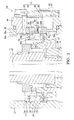
FIG. 1 is a longitudinal sectional view of an electric power steering apparatus to which a torque sensor according to a first embodiment of the present invention is applied. -
FIG. 2 is a partially enlarged view ofFIG. 1 . -
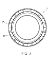
FIG. 3 is a bottom view of a magnetism generation portion. -
FIG. 4 is a perspective view of the torque sensor according to the first embodiment of the present invention in a condition where a housing has been removed. -
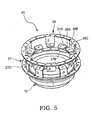
FIG. 5 is a perspective view of a rotating magnetic circuit portion. -
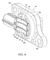
FIG. 6 is a perspective view of a sensor holder. -
FIG. 7 is a perspective view of a magnetic flux collecting yoke. -
FIG. 8 is a view showing a magnetic flux path, wherein solid line arrows show a normal magnetic flux path and a dotted line arrow shows a path of flux leakage. -
FIG. 9 is a graph showing a detection error in the torque sensor due to an effect of flux leakage. -
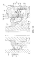
FIG. 10 is a partial longitudinal sectional view of an electric power steering apparatus to which a torque sensor according to a second embodiment of the present invention is applied. -
FIG. 11 is a perspective view of the torque sensor according to the second embodiment of the present invention in a condition where a housing has been removed. -
FIG. 12 is a perspective view of a sensor holder. -
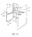
FIG. 13 is a perspective view of a magnetic flux collecting yoke. -
FIG. 14 is a longitudinal sectional view of an electric power steering apparatus to which a torque sensor according to a third embodiment of the present invention is applied. -
FIG. 15 is a partially enlarged view ofFIG. 14 . -
FIG. 16 is a perspective view of the torque sensor according to the third embodiment of the present invention in a condition where a housing has been removed. -
FIG. 17 is a perspective view of the housing. -
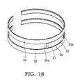
FIG. 18 is a perspective view of a magnetic flux collecting ring. -
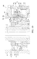
FIG. 19 is a partial longitudinal sectional view of an electric power steering apparatus to which a torque sensor according to a fourth embodiment of the present invention is applied. -
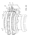
FIG. 20 is a perspective view of the torque sensor according to the fourth embodiment of the present invention in a condition where a housing has been removed. -
FIG. 21 is a perspective view of the housing. -
FIG. 22 is a perspective view of a magnetic flux collecting ring. -
FIG. 23 is a view showing a normal magnetic flux path and a path of flux leakage, wherein straight line arrows show the normal magnetic flux path and curved line arrows show the path of the flux leakage. - Referring to the figures, embodiments of the present invention will be described.
- Referring to
FIGS. 1 to 9 , atorque sensor 100 according to a first embodiment of the present invention will be described. - First, referring to
FIG. 1 , an electricpower steering apparatus 1 to which thetorque sensor 100 according to the first embodiment of the present invention is applied will be described. - In the electric
power steering apparatus 1, asteering shaft 10 and anoutput shaft 12 rotate in conjunction with a steering wheel such that a rack shaft that meshes with a pinion provided on a lower end of theoutput shaft 12 moves in an axial direction. As a result, a vehicle wheel is steered. - Further, the electric
power steering apparatus 1 includes, as an assist mechanism for applying auxiliary steering torque, a worm wheel coupled to theoutput shaft 12, a worm that meshes with the worm wheel, and an electric motor that drives the worm to rotate. The electricpower steering apparatus 1 uses the electric motor to apply the auxiliary steering torque to theoutput shaft 12. - The
steering shaft 10 includes aninput shaft 11 serving as a first shaft, and atorsion bar 21 coupled to theinput shaft 11. Theinput shaft 11 is supported on ahousing 30 to be free to rotate via a roller bearing 37. Theoutput shaft 12, which serves as a second shaft, is supported on ahousing 49 to be free to rotate via a roller bearing 38. A slide bearing 39 is interposed between a lower end side of theinput shaft 11 and an upper end side of theoutput shaft 12. Theinput shaft 11 and theoutput shaft 12 are supported on thehousings - The
input shaft 11 is formed in a cylindrical shape, and thetorsion bar 21 is housed in the interior of theinput shaft 11 coaxially therewith. An upper end portion of thetorsion bar 21 is coupled to an upper end portion of theinput shaft 11 via apin 28. A lower end portion of thetorsion bar 21 projects from a lower end opening portion of theinput shaft 11, and is coupled to theoutput shaft 12 via aserration 29. Thetorsion bar 21 transmits steering torque input into theinput shaft 11 via a steering wheel to theoutput shaft 12, and undergoes torsional deformation about a rotary axis O in accordance with the steering torque. - The electric
power steering apparatus 1 is provided with the non-contacttype torque sensor 100, which detects the steering torque acting on thetorsion bar 21 that connects theinput shaft 11 to theoutput shaft 12. Thetorque sensor 100 will be described below. - The
torque sensor 100 includes amagnetism generation portion 22 fixed to theinput shaft 11 so as to rotate together with theinput shaft 11, a rotatingmagnetic circuit portion 25 fixed to theoutput shaft 12 so as to rotate together with theoutput shaft 12, a fixedmagnetic circuit portion 31 fixed to thehousing 30, and amagnetism sensor 48 serving as a magnetism detector for detecting a magnetic flux density that is guided to the fixedmagnetic circuit portion 31 from themagnetism generation portion 22 via the rotatingmagnetic circuit portion 25 in accordance with the torsional deformation of thetorsion bar 21. Thetorque sensor 100 detects the steering torque acting on thetorsion bar 21 on the basis of an output of themagnetism sensor 48. - Instead of the configuration described above, the
magnetism generation unit 22 may be fixed to theoutput shaft 12 so as to rotate together with theoutput shaft 12, and the rotatingmagnetic circuit portion 25 may be fixed to theinput shaft 11 so as to rotate together with theinput shaft 11. - As shown in
FIGS. 1 to 3 , themagnetism generation portion 22 includes anannular back yoke 24 press-fitted to theinput shaft 11, and anannular ring magnet 23 joined to a lower end surface of theback yoke 24. - The
ring magnet 23 is an annular permanent magnet that generates magnetism in the direction of the rotary axis O of theinput shaft 11. Thering magnet 23 is a multipolar magnet formed by polarizing a hard magnetic material in the rotary axis O direction, and has twelve magnetic poles formed at equal widths in a circumferential direction. In other words, six N poles and six S poles are disposed alternately in the circumferential direction on an upper end surface and a lower end surface of thering magnet 23. The number of magnetic poles formed on the end surfaces of thering magnet 23 may be set as desired within a range of two or more. - An upper portion magnetic pole surface serving as the upper end surface of the
ring magnet 23 is fixed to the lower end surface of theback yoke 24 via an adhesive. Further, theback yoke 24 is formed from a soft magnetic material, and is therefore magnetized by a magnetic field exerted thereon by thering magnet 23 so as to be adsorbed to thering magnet 23. Hence, thering magnet 23 and theback yoke 24 are joined by both an adhesive force of the adhesive and a magnetic force. Theback yoke 24 functions both as a connecting member that connects thering magnet 23 to theinput shaft 11, and a yoke that guides magnetic flux by linking adjacent magnetic poles of thering magnet 23, whereby a magnetic force is collected on a lower portion magnetic pole surface serving as the lower end surface of thering magnet 23. - As shown in
FIGS. 1 ,2 ,4 , and5 , the rotatingmagnetic circuit portion 25 includes a first softmagnetic ring 26 and a second softmagnetic ring 27 to which magnetic flux generated by thering magnet 23 of themagnetism generation portion 22 is guided, anattachment member 70 attached to theoutput shaft 12, and amold resin 71 for fixing the first softmagnetic ring 26 and the second softmagnetic ring 27 to theattachment member 70. - The first soft
magnetic ring 26 includes an annular first magneticpath ring portion 26C, six first magneticpath column portions 26B projecting downward from the first magneticpath ring portion 26C, and first magnetic path tipend portions 26A that are bent inward from lower ends of the respective first magneticpath column portions 26B so as to face the lower end surface of thering magnet 23. The second softmagnetic ring 27 includes an annular second magneticpath ring portion 27C, six second magneticpath column portions 27B projecting upward from the second magneticpath ring portion 27C, and second magnetic path tipend portions 27A that are bent inward from upper ends of the respective second magneticpath column portions 27B so as to face the lower end surface of thering magnet 23. - The first soft
magnetic ring 26 and the second softmagnetic ring 27 are respectively formed by pressing. The first softmagnetic ring 26 and the second softmagnetic ring 27 are not limited to pressing, and may be formed by casting, sintering, and so on. - The first magnetic path tip
end portions 26A and the second magnetic path tipend portions 27A are formed in a flat plate shape. The first magnetic path tipend portions 26A and the second magnetic path tipend portions 27A are disposed alternately at equal intervals in the circumferential direction about the rotary axis O of thetorsion bar 21 on an identical plane that is orthogonal to the rotary axis O. - Further, the first magnetic path tip
end portions 26A and the second magnetic path tipend portions 27A are disposed such that in a neutral condition where no torque acts on thetorsion bar 21, center lines extending respectively in a radial direction of thetorsion bar 21 denote boundaries between the N poles and the S poles of thering magnet 23. - The first magnetic
path column portions 26B and the second magneticpath column portions 27B are respectively formed in a flat plate shape so as to extend in the rotary axis O direction. The first magneticpath column portions 26B are disposed at predetermined intervals so as to surround an outer peripheral surface of thering magnet 23. The first magneticpath column portions 26B are provided so as not to short-circuit the magnetic flux of thering magnet 23. Further, the second magneticpath column portions 27B are provided to extend along the rotary axis O in an opposite direction to the first magneticpath column portions 26B. - The first magnetic
path ring portion 26C and the second magneticpath ring portion 27C are disposed on an orthogonal plane to the rotary axis O and formed in a ring shape having a fully connected circumference. The first magneticpath ring portion 26C and the second magneticpath ring portion 27C are not limited to this shape, and may be formed in a C shape having a slit in a part thereof. - The first magnetic
path ring portion 26C is disposed above the lower end surface of thering magnet 23, and the second magneticpath ring portion 27C is disposed below thering magnet 23. In other words, thering magnet 23 is disposed between the first magneticpath ring portion 26C and the second magneticpath ring portion 27C in the rotary axis O direction. - As shown in
FIGS. 1 ,2 ,4 ,6 , and7 , the fixedmagnetic circuit portion 31 includes a first magneticflux collecting ring 32 provided along an outer periphery of the first magneticpath ring portion 26C of the first softmagnetic ring 26, a second magneticflux collecting ring 33 provided along an outer periphery of the second magneticpath ring portion 27C of the second softmagnetic ring 27, a first magneticflux collecting yoke 34 connected to the first magneticflux collecting ring 32, and a second magneticflux collecting yoke 35 connected to the second magneticflux collecting ring 33. It should be noted that the first magneticflux collecting ring 32 and the second magneticflux collecting ring 33 are partially omitted fromFIG. 4 . - The first magnetic
flux collecting ring 32 and the second magneticflux collecting ring 33 are formed in a C shape having a slit in a part thereof, and fixed to an inner peripheral surface of thehousing 30 by caulking. An inner peripheral surface of the first magneticflux collecting ring 32 faces the first magneticpath ring portion 26C of the first softmagnetic ring 26, and an inner peripheral surface of the second magneticflux collecting ring 33 faces the second magneticpath ring portion 27C of the second softmagnetic ring 27. - Hence, the first magnetic
flux collecting ring 32 and the second magneticflux collecting ring 33 are disposed on an outer periphery of the rotatingmagnetic circuit portion 25 so as to guide magnetic flux to themagnetism sensor 48 side after reducing effects of rotation fluctuation and eccentricity in the rotatingmagnetic circuit portion 25. - The first magnetic
flux collecting yoke 34 is formed in a block shape having an arc-shaped innerperipheral surface 34a that contacts an outer peripheral surface of the first magneticflux collecting ring 32. The second magneticflux collecting yoke 35 is formed in a block shape having an arc-shaped innerperipheral surface 35a that contacts an outer peripheral surface of the second magneticflux collecting ring 33. - A pair of magnetic flux collecting projecting
portions 34b are provided on the first magneticflux collecting yoke 34 to extend in the rotary axis O direction, and a pair of magnetic flux collecting projectingportions 35b are provided on the second magneticflux collecting yoke 35 to extend in the rotary axis O direction. The pair of magnetic flux collecting projectingportions 34b of the first magneticflux collecting yoke 34 and the pair of magnetic flux collecting projectingportions 35b of the second magneticflux collecting yoke 35 respectively oppose each other via predetermined gaps serving as magnetic gaps. In other words, a pair of magnetic gaps arranged in the circumferential direction is formed between the first magneticflux collecting yoke 34 and the second magneticflux collecting yoke 35. Themagnetism sensor 48 is disposed in each magnetic gap. - The first magnetic
flux collecting yoke 34 and the second magneticflux collecting yoke 35 have a function for collecting magnetic flux from the rotatingmagnetic circuit portion 25 on themagnetism sensors 48 via the first magneticflux collecting ring 32 and the second magneticflux collecting ring 33. - The first magnetic
flux collecting yoke 34, the second magneticflux collecting yoke 35, themagnetism sensors 48, and asubstrate 47 are fixed to asensor holder 40 via mold resin. Acylindrical portion 40a of theresin sensor holder 40 is fitted into anopening portion 30a of thehousing 30, and thesensor holder 40 is attached to themetal housing 30 via a bolt inserted into afastening hole 40b thereof. - A Hall element is used as the
magnetism sensor 48 for detecting magnetism. The Hall element outputs a voltage as a signal corresponding to a magnetic flux density passing through itself. Themagnetism sensor 48 outputs a voltage corresponding to a magnitude and a direction of a magnetic field in the magnetic gap via thesubstrate 47 and a terminal 44. The terminal 44 is connected to a controller via a wire connected to thesensor holder 40. A circuit for amplifying the signal from the Hall element, a circuit for performing temperature compensation, a noise filter circuit, and so on may be included in themagnetism sensor 48. - The
magnetism sensor 48 is provided in a pair in accordance with the pair of magnetic gaps formed between the first magneticflux collecting yoke 34 and the second magneticflux collecting yoke 35 and arranged in the circumferential direction. One of themagnetism sensors 48 forms a main system, and the other forms a sub-system. An output voltage output from themagnetism sensor 48 of the main system is used to control the electric motor of the electricpower steering apparatus 1. An output voltage output from themagnetism sensor 48 of the sub-system is used by the controller to diagnose an abnormality in thetorque sensor 100. More specifically, the controller compares steering torque detected in the main system with steering torque detected in the sub-system, and determines that an abnormality has occurred in thetorque sensor 100 when a difference therebetween is determined to equal or exceed a predetermined allowable difference. - Next, a method of detecting the steering torque acting on the
torsion bar 21 using thetorque sensor 100 will be described. - In the neutral condition where no torque acts on the
torsion bar 21, the first magnetic path tipend portions 26A of the first softmagnetic ring 26 and the second magnetic path tipend portions 27A of the second softmagnetic ring 27 respectively face the N poles and the S poles of thering magnet 23 by an identical surface area so as to be magnetically short-circuited. As a result, no magnetic flux is guided to the rotatingmagnetic circuit portion 25 and the fixedmagnetic circuit portion 31. - When torque in a specific direction is exerted on the
torsion bar 21 in response to an operation of the steering wheel by a driver, thetorsion bar 21 undergoes torsional deformation in accordance with the direction of the torque. When thetorsion bar 21 undergoes torsional deformation, the first magnetic path tipend portions 26A face the N poles by a greater surface area than the S poles, while the second magnetic path tipend portions 27A face the S poles by a greater surface area than the N poles. Accordingly, the magnetic flux from thering magnet 23 is guided to the fixedmagnetic circuit portion 31 through the rotatingmagnetic circuit portion 25. More specifically, a resulting magnetic path extends from the N pole to the S pole via the first softmagnetic ring 26, the first magneticflux collecting ring 32, the first magneticflux collecting yoke 34, the second magneticflux collecting yoke 35, the second magneticflux collecting ring 33, and the second softmagnetic ring 27. Themagnetism sensors 48 disposed in the magnetic gaps between the first magneticflux collecting yoke 34 and the second magneticflux collecting yoke 35 output signals corresponding to the magnitude and the direction of the magnetic flux. - When torque is exerted on the
torsion bar 21 in an opposite direction to the above direction in response to an operation of the steering wheel by the driver, thetorsion bar 21 undergoes torsional deformation in an opposite direction in accordance with the direction of the torque. When thetorsion bar 21 undergoes torsional deformation, the first magnetic path tipend portions 26A face the S poles by a greater surface area than the N poles, while the second magnetic path tipend portions 27A face the N poles by a greater surface area than the S poles. Accordingly, the magnetic flux from thering magnet 23 is guided to the fixedmagnetic circuit portion 31 through the rotatingmagnetic circuit portion 25 along an opposite path to that described above. More specifically, the magnetic path extends from the N pole to the S pole via the second softmagnetic ring 27, the second magneticflux collecting ring 33, the second magneticflux collecting yoke 35, the first magneticflux collecting yoke 34, the first magneticflux collecting ring 32, and the first softmagnetic ring 26. Themagnetism sensors 48 disposed in the magnetic gaps between the first magneticflux collecting yoke 34 and the second magneticflux collecting yoke 35 output signals corresponding to the magnitude and the direction of the magnetic flux. - The magnetic flux guided to the magnetic gaps increases as a surface area difference by which the first magnetic path tip
end portions 26A face the N poles and the S poles of thering magnet 23 and a surface area difference by which the second magnetic path tipend portions 27A face the N poles and the S poles of thering magnet 23 increase, and as a result, the output signals from themagnetism sensors 48 also increase. Therefore, by increasing the number of magnetic poles on thering magnet 23, the magnetic flux density guided to themagnetism sensors 48 can be increased. - Here, referring to
FIGS. 8 ,9 , and23 , flux leakage in the rotatingmagnetic circuit portion 25 will be described. -
FIG. 8 is a view showing a magnetic flux path in a case where thetorsion bar 21 undergoes torsional deformation such that the first magnetic path tipend portions 26A of the first softmagnetic ring 26 face the N poles by a larger surface area than the S poles and the second magnetic path tipend portions 27A of the second softmagnetic ring 27 face the S poles by a larger surface area than the N poles. Solid line arrows show a normal magnetic flux path, and a dotted line arrow shows a path of flux leakage. - The flux leakage is guided from the first soft
magnetic ring 26 to the second softmagnetic ring 27 so as to bypass themagnetism sensors 48. Hence, a flux leakage path (the path indicated by curved line arrows inFIG. 23 ) that short-circuits the first softmagnetic ring 26 and the second softmagnetic ring 27 exists in the rotatingmagnetic circuit portion 25 separately to the normal magnetic flux path. The flux leakage path extends from the N pole of thering magnet 23 toward the S pole through the first softmagnetic ring 26 and the second softmagnetic ring 27, and therefore exists in a number corresponding to the number of magnetic poles. In this embodiment, thering magnet 23 includes six pairs of N and S poles, and therefore six magnetic flux paths that short-circuit the first softmagnetic ring 26 and the second softmagnetic ring 27 exist. -
FIG. 9 is a graph showing a detection error of thetorque sensor 100 due to an effect of flux leakage. The abscissa inFIG. 9 shows a rotation angle of theinput shaft 11, and the ordinate shows the steering torque (detected torque) detected by thetorque sensor 100. Further, a solid line inFIG. 9 shows the detected torque of the main system, and a dotted line shows the detected torque of the sub-system. -
FIG. 9 shows the detected torque of thetorque sensor 100 in a case where theinput shaft 11 is rotated by a single revolution such that the steering torque acting on thetorsion bar 21 remains constant. Since the steering torque acting on thetorsion bar 21 is constant, the detected torque of thetorque sensor 100 should also be constant. As shown inFIG. 9 , however, the detected torque of thetorque sensor 100 varies in 60° periods. The reason for this is that the six flux leakage paths short-circuiting the first softmagnetic ring 26 and the second softmagnetic ring 27 exist, as described above, and these six flux leakages are detected as density variation accompanying rotation of theinput shaft 11. Hence, thetorque sensor 100 also detects variation in the flux leakage that is dependent on the rotation angle of theinput shaft 11, or in other words variation in the flux leakage that is not related to the torsional deformation of thetorsion bar 21. - When the
magnetism sensors 48 pick up the flux leakage variation (an error component) that is not related to the torsional deformation of thetorsion bar 21, themagnetism sensors 48 detect a magnetic flux density in which the flux leakage variation that is not related to the torsional deformation of thetorsion bar 21 is superimposed on a true magnetic flux density accompanying torsional deformation of thetorsion bar 21, and as a result, a detection error is generated in thetorque sensor 100. When a detection error is generated in thetorque sensor 100, an error occurs in the auxiliary steering torque applied to theoutput shaft 12 by the electric motor. Therefore, in a case where highly precise control is required of the electricpower steering apparatus 1, it is necessary to prevent a detection error from occurring in thetorque sensor 100 due to flux leakage variation that is not related to the torsional deformation of thetorsion bar 21. - For this purpose, as shown in
FIGS. 2 ,4 ,6 , and7 , ashield 50 that guides the flux leakage between the first magneticflux collecting yoke 34 and the second magneticflux collecting yoke 35 while magnetically shielding themagnetism sensors 48 from the flux leakage is disposed between the rotatingmagnetic circuit portion 25 and themagnetism sensors 48. - The
shield 50 takes an arc shape having a substantially identical curvature radius to the innerperipheral surfaces flux collecting yoke 34 and the second magneticflux collecting yoke 35, and is formed from a magnetic material, or more specifically a soft magnetic material. - The
shield 50 is molded integrally with the sensor holder 40 (seeFIG. 6 ) via the mold resin together with the first magneticflux collecting yoke 34 and the second magneticflux collecting yoke 35. More specifically, theshield 50 is fixed to mold resin 51 (seeFIG. 2 ). Themold resin 51 is formed between the first magneticflux collecting yoke 34 and the second magneticflux collecting yoke 35 and supports the twoyokes shield 50 and themold resin 51 are molded integrally by insert molding or outsert molding. - The
shield 50 is disposed such that an innerperipheral surface 50a thereof is coplanar with the innerperipheral surfaces flux collecting yoke 34 and the second magneticflux collecting yoke 35 via respectivepredetermined gaps - By disposing the
shield 50 between the first magneticflux collecting yoke 34 and the second magneticflux collecting yoke 35, the flux leakage in the rotatingmagnetic circuit portion 25 is guided by theshield 50 so as not to reach themagnetism sensors 48. Hence, themagnetism sensors 48 are magnetically shielded from the flux leakage in the rotatingmagnetic circuit portion 25 by theshield 50, and are not therefore affected by flux leakage variation not related to the torsional deformation of thetorsion bar 21. Accordingly, a detection error does not occur in thetorque sensor 100, and as a result, the detection precision of thetorque sensor 100 improves. - When the
gap 52 between theshield 50 and the first magneticflux collecting yoke 34 and thegap 53 between theshield 50 and the second magneticflux collecting yoke 35 are too small, the first magneticflux collecting yoke 34 and the second magneticflux collecting yoke 35 are short-circuited via theshield 50, leading to a reduction in the magnetic flux density detected by themagnetism sensors 48. Thegaps magnetism sensors 48 can be magnetically shielded from the flux leakage in the rotatingmagnetic circuit portion 25 while suppressing a reduction in the magnetic flux density detected by themagnetism sensors 48. - According to the first embodiment, described above, following effects are obtained.
- By providing the
shield 50 between the first magneticflux collecting yoke 34 and the second magneticflux collecting yoke 35, the flux leakage in the rotatingmagnetic circuit portion 25 is guided by theshield 50 so as to be guided from the first magneticflux collecting yoke 34 to the second magneticflux collecting yoke 35 or from the second magneticflux collecting yoke 35 to the first magneticflux collecting yoke 34 while bypassing themagnetism sensors 48. Hence, the flux leakage in the rotatingmagnetic circuit portion 25 does not reach themagnetism sensors 48, and therefore themagnetism sensors 48 are not affected by flux leakage variation not related to the torsional deformation of thetorsion bar 21. Accordingly, a detection error caused by the flux leakage in the rotatingmagnetic circuit portion 25 does not occur in thetorque sensor 100, and as a result, the detection precision of thetorque sensor 100 improves. - By providing the
shield 50, a detection error caused by the flux leakage in the rotatingmagnetic circuit portion 25 does not occur in thetorque sensor 100, and therefore themagnetism sensors 48 can be disposed closer to the input andoutput shafts torque sensor 100. - Next, referring to
FIGS. 10 to 13 , atorque sensor 200 according to a second embodiment of the present invention will be described. Only differences with the first embodiment will be described below, while identical configurations to the first embodiment have been allocated identical reference symbols and description thereof has been omitted. - The
torque sensor 200 differs from the first embodiment in the configuration of ashield 60 that guides flux leakage between the first magneticflux collecting yoke 34 and the second magneticflux collecting yoke 35. In the first embodiment, theshield 50 is formed separately to the first magneticflux collecting yoke 34 and the second magneticflux collecting yoke 35, whereas theshield 60 of thetorque sensor 200 is formed integrally with the first magneticflux collecting yoke 34 and the second magneticflux collecting yoke 35. Theshield 60 will be described in detail below. - The first magnetic
flux collecting yoke 34 and the second magneticflux collecting yoke 35 respectively include afirst extension portion 34c and asecond extension portion 35c formed by extending respective parts thereof. Thefirst extension portion 34c and thesecond extension portion 35c are formed to extend in a mutually approaching direction, and disposed so as to face each other via apredetermined gap 61. - The
shield 60 is constituted by thefirst extension portion 34c and thesecond extension portion 35c disposed to face each other via thepredetermined gap 61, and is disposed between the rotatingmagnetic circuit portion 25 and themagnetism sensors 48. Theshield 60 has a similar function to theshield 50 according to the first embodiment. In other words, theshield 60 guides the flux leakage between the first magneticflux collecting yoke 34 and the second magneticflux collecting yoke 35 while magnetically shielding themagnetism sensors 48 from the flux leakage. - Similarly to the first embodiment, the
gap 61 between thefirst extension portion 34c and thesecond extension portion 35c is set at a dimension at which themagnetism sensors 48 can be magnetically shielded from the flux leakage in the rotatingmagnetic circuit portion 25 while suppressing a reduction in the magnetic flux density detected by themagnetism sensors 48. - According to the second embodiment, described above, following effects are obtained.
- By providing the
shield 60 that is formed integrally with the first magneticflux collecting yoke 34 and the second magneticflux collecting yoke 35, the flux leakage in the rotatingmagnetic circuit portion 25 is guided by theshield 60 so as to be guided from the first magneticflux collecting yoke 34 to the second magneticflux collecting yoke 35 or from the second magneticflux collecting yoke 35 to the first magneticflux collecting yoke 34 while bypassing themagnetism sensors 48. Hence, the flux leakage in the rotatingmagnetic circuit portion 25 does not reach themagnetism sensors 48, and therefore themagnetism sensors 48 are not affected by flux leakage variation not related to the torsional deformation of thetorsion bar 21. Accordingly, a detection error caused by the flux leakage in the rotatingmagnetic circuit portion 25 does not occur in thetorque sensor 200, and as a result, the detection precision of thetorque sensor 200 improves. - Further, by providing the
shield 60, a detection error caused by the flux leakage in the rotatingmagnetic circuit portion 25 does not occur in thetorque sensor 200, and therefore themagnetism sensors 48 can be disposed closer to the input andoutput shafts torque sensor 200. - Moreover, the
shield 60 is constituted by thefirst extension portion 34c and thesecond extension portion 35c formed by partially extending the first magneticflux collecting yoke 34 and the second magneticflux collecting yoke 35, and therefore a number of components can be reduced in comparison with thetorque sensor 100 according to the first embodiment, in which theshield 50 is provided separately to the first magneticflux collecting yoke 34 and the second magneticflux collecting yoke 35. - Next, referring to
FIGS. 14 to 18 , atorque sensor 300 according to a third embodiment of the present invention will be described. Only differences with the first embodiment will be described below, while identical configurations to the first embodiment have been allocated identical reference symbols and description thereof has been omitted. - A
shield 55 that guides the flux leakage between the first magneticflux collecting ring 32 and the second magneticflux collecting ring 33 while magnetically shielding themagnetism sensors 48 from the flux leakage is disposed between the rotatingmagnetic circuit portion 25 and themagnetism sensors 48. - The
shield 55 is formed in an arc shape having a substantially identical curvature radius to the first magneticflux collecting ring 32 and the second magneticflux collecting ring 33, and has a substantially identical thickness to the first magneticflux collecting ring 32 and the second magneticflux collecting ring 33. Theshield 55 is formed from a magnetic material, or more specifically a soft magnetic material. - The
shield 55 is molded integrally with thehousing 30. More specifically, as shown inFIG. 17 , theshield 55 is fixed to aresin material 56. Theresin material 56 is joined to an inner peripheral surface of theopening portion 30a of thehousing 30, and formed to traverse theopening portion 30a. Theshield 55 and theresin material 56 are molded integrally by insert molding or outsert molding.Notches 55a for inserting pins used to position theshield 55 during integral molding of theshield 55 and theresin material 56 are formed in respective end portions of theshield 55. - Instead of molding the
shield 55 and thehousing 30 integrally, theshield 55 may be molded integrally with thesensor holder 40. In this case, theshield 55 is fixed to the mold resin 51 (seeFIG. 2 ) that is formed between the first magneticflux collecting yoke 34 and the second magneticflux collecting yoke 35 and that supports the twoyokes - The
shield 55 is disposed between the first magneticflux collecting ring 32 and the second magneticflux collecting ring 33 via respectivepredetermined gaps - By disposing the
shield 55 between the first magneticflux collecting ring 32 and the second magneticflux collecting ring 33, the flux leakage in the rotatingmagnetic circuit portion 25 is guided by theshield 55 so as not to reach themagnetism sensors 48. Hence, themagnetism sensors 48 are magnetically shielded from the flux leakage in the rotatingmagnetic circuit portion 25 by theshield 55, and are not therefore affected by flux leakage variation not related to the torsional deformation of thetorsion bar 21. Accordingly, a detection error does not occur in thetorque sensor 300, and as a result, the detection precision of thetorque sensor 300 improves. - When the
gap 57 between theshield 55 and the first magneticflux collecting ring 32 and thegap 58 between theshield 55 and the second magneticflux collecting ring 33 are too small, the first magneticflux collecting ring 32 and the second magneticflux collecting ring 33 are short-circuited via theshield 55, leading to a reduction in the magnetic flux density detected by themagnetism sensors 48. Thegaps magnetism sensors 48 can be magnetically shielded from the flux leakage in the rotatingmagnetic circuit portion 25 while suppressing a reduction in the magnetic flux density detected by themagnetism sensors 48. - According to the third embodiment, described above, following effects are obtained.
- By providing the
shield 55 between the first magneticflux collecting ring 32 and the second magneticflux collecting ring 33, the flux leakage in the rotatingmagnetic circuit portion 25 is guided by theshield 55 so as to be guided from the first magneticflux collecting ring 32 to the second magneticflux collecting ring 33 or from the second magneticflux collecting ring 33 to the first magneticflux collecting ring 32 while bypassing themagnetism sensors 48. Hence, the flux leakage in the rotatingmagnetic circuit portion 25 does not reach themagnetism sensors 48, and therefore themagnetism sensors 48 are not affected by flux leakage variation not related to the torsional deformation of thetorsion bar 21. Accordingly, a detection error caused by the flux leakage in the rotatingmagnetic circuit portion 25 does not occur in thetorque sensor 300, and as a result, the detection precision of thetorque sensor 300 improves. - By providing the
shield 55, a detection error caused by the flux leakage in the rotatingmagnetic circuit portion 25 does not occur in thetorque sensor 300, and therefore themagnetism sensors 48 can be disposed closer to the input andoutput shafts torque sensor 300. - Next, referring to
FIGS. 19 to 22 , atorque sensor 400 according to a fourth embodiment of the present invention will be described. Only differences with the third embodiment will be described below, while identical configurations to the third embodiment have been allocated identical reference symbols and description thereof has been omitted. - The
torque sensor 400 differs from the third embodiment in the configuration of ashield 65 that guides flux leakage between the first magneticflux collecting ring 32 and the second magneticflux collecting ring 33. In the third embodiment, theshield 55 is formed separately to the first magneticflux collecting ring 32 and the second magneticflux collecting ring 33, whereas theshield 65 of thetorque sensor 400 is formed integrally with the first magneticflux collecting ring 32 and the second magneticflux collecting ring 33. Theshield 65 will be described in detail below. - The first magnetic
flux collecting ring 32 and the second magneticflux collecting ring 33 respectively include afirst extension portion 32a and asecond extension portion 33a formed by extending respective parts thereof. Thefirst extension portion 32a and thesecond extension portion 33a are formed to extend in a mutually approaching direction, and disposed so as to face each other via apredetermined gap 66. - The
shield 65 is constituted by thefirst extension portion 32a and thesecond extension portion 33a disposed to face each other via thepredetermined gap 66, and is disposed between the rotatingmagnetic circuit portion 25 and themagnetism sensor 48. Theshield 65 has a similar function to theshield 55 according to the third embodiment. In other words, theshield 65 guides the flux leakage between the first magneticflux collecting ring 32 and the second magneticflux collecting ring 33 while magnetically shielding themagnetism sensors 48 from the flux leakage. - Similarly to the third embodiment, the
gap 66 between thefirst extension portion 32a and thesecond extension portion 33a is set at a dimension at which themagnetism sensors 48 can be magnetically shielded from the flux leakage in the rotatingmagnetic circuit portion 25 while suppressing a reduction in the magnetic flux density detected by themagnetism sensors 48. - According to the fourth embodiment, described above, following effects are obtained.
- By providing the
shield 65 that is formed integrally with the first magneticflux collecting ring 32 and the second magneticflux collecting ring 33, the flux leakage in the rotatingmagnetic circuit portion 25 is guided by theshield 65 so as to be guided from the first magneticflux collecting ring 32 to the second magneticflux collecting ring 33 or from the second magneticflux collecting ring 33 to the first magneticflux collecting ring 32 while bypassing themagnetism sensors 48. Hence, the flux leakage in the rotatingmagnetic circuit portion 25 does not reach themagnetism sensors 48, and therefore themagnetism sensors 48 are not affected by flux leakage variation not related to the torsional deformation of thetorsion bar 21. Accordingly, a detection error caused by the flux leakage in the rotatingmagnetic circuit portion 25 does not occur in thetorque sensor 400, and as a result, the detection precision of thetorque sensor 400 improves. - Further, by providing the
shield 65, a detection error caused by the flux leakage in the rotatingmagnetic circuit portion 25 does not occur in thetorque sensor 400, and therefore themagnetism sensors 48 can be disposed closer to the input andoutput shafts torque sensor 400. - Moreover, the
shield 65 is constituted by thefirst extension portion 32a and thesecond extension portion 33a formed by partially extending the first magneticflux collecting ring 32 and the second magneticflux collecting ring 33, and therefore the number of components can be reduced in comparison with thetorque sensor 300 according to the third embodiment, in which theshield 55 is provided separately to the first magneticflux collecting ring 32 and the second magneticflux collecting ring 33. - Embodiments of this invention were described above, but the above embodiments are merely examples of applications of this invention, and the technical scope of this invention is not limited to the specific constitutions of the above embodiments.
- This application claims priority based on Japanese Patent Application No.
2012-65755 2012-65765 - The present invention can be used as a torque sensor employed in an electric power steering apparatus that assists a steering force applied by a driver to a steering wheel.
Claims (7)
- A torque sensor that detects torque acting on a torsion bar that connects a first shaft and a second shaft, which are supported in a housing to be free to rotate, comprising:a magnetism generation portion that rotates together with the first shaft;a rotating magnetic circuit portion that rotates together with the second shaft;a fixed magnetic circuit portion fixed to the housing;a magnetism detector that detects a magnetic flux density guided from the magnetism generation portion to the fixed magnetic circuit portion through the rotating magnetic circuit portion in accordance with torsional deformation of the torsion bar; anda shield disposed between the rotating magnetic circuit portion and the magnetism detector in order to shield the magnetism detector magnetically.
- The torque sensor as defined in Claim 1, wherein the rotating magnetic circuit portion comprises a first soft magnetic ring and a second soft magnetic ring to which magnetic flux generated by the magnetism generation portion is guided in accordance with the torsional deformation of the torsion bar,
the fixed magnetic circuit portion comprises:a first magnetic flux collecting ring and a second magnetic flux collecting ring provided along respective outer peripheries of the first soft magnetic ring and the second soft magnetic ring; anda first magnetic flux collecting yoke and a second magnetic flux collecting yoke connected respectively to the first magnetic flux collecting ring and the second magnetic flux collecting ring and disposed so as to face each other via a magnetic gap in which the magnetism detector is disposed, andthe shield is disposed to guide flux leakage generated in the rotating magnetic circuit portion between the first magnetic flux collecting yoke and the second magnetic flux collecting yoke. - The torque sensor as defined in Claim 2, wherein the shield is disposed between the first magnetic flux collecting yoke and the second magnetic flux collecting yoke via respective predetermined gaps.
- The torque sensor as defined in Claim 2, wherein the first magnetic flux collecting yoke and the second magnetic flux collecting yoke respectively include a first extension portion and a second extension portion formed by extending respective parts thereof, and
the shield is constituted by the first extension portion and the second extension portion, which are disposed to face each other via a predetermined gap. - The torque sensor as defined in Claim 1, wherein the rotating magnetic circuit portion comprises a first soft magnetic ring and a second soft magnetic ring to which magnetic flux generated by the magnetism generation portion is guided in accordance with the torsional deformation of the torsion bar,
the fixed magnetic circuit portion comprises a first magnetic flux collecting ring and a second magnetic flux collecting ring provided along respective outer peripheries of the first soft magnetic ring and the second soft magnetic ring, and
the shield is disposed to guide flux leakage generated in the rotating magnetic circuit portion between the first magnetic flux collecting ring and the second magnetic flux collecting ring. - The torque sensor as defined in Claim 5, wherein the shield is disposed between the first magnetic flux collecting ring and the second magnetic flux collecting ring via respective predetermined gaps.
- The torque sensor as defined in Claim 5, wherein the first magnetic flux collecting ring and the second magnetic flux collecting ring respectively include a first extension portion and a second extension portion formed by extending respective parts thereof, and
the shield is constituted by the first extension portion and the second extension portion, which are disposed to face each other via a predetermined gap.
Applications Claiming Priority (3)
| Application Number | Priority Date | Filing Date | Title |
|---|---|---|---|
| JP2012065765A JP5852485B2 (en) | 2012-03-22 | 2012-03-22 | Torque sensor |
| JP2012065755A JP5852484B2 (en) | 2012-03-22 | 2012-03-22 | Torque sensor |
| PCT/JP2013/052257 WO2013140864A1 (en) | 2012-03-22 | 2013-01-31 | Torque sensor |
Publications (3)
| Publication Number | Publication Date |
|---|---|
| EP2829858A1 true EP2829858A1 (en) | 2015-01-28 |
| EP2829858A4 EP2829858A4 (en) | 2015-09-30 |
| EP2829858B1 EP2829858B1 (en) | 2019-09-11 |
Family
ID=49222331
Family Applications (1)
| Application Number | Title | Priority Date | Filing Date |
|---|---|---|---|
| EP13763845.8A Active EP2829858B1 (en) | 2012-03-22 | 2013-01-31 | Torque sensor |
Country Status (4)
| Country | Link |
|---|---|
| US (1) | US9435703B2 (en) |
| EP (1) | EP2829858B1 (en) |
| CN (1) | CN104169701B (en) |
| WO (1) | WO2013140864A1 (en) |
Families Citing this family (15)
| Publication number | Priority date | Publication date | Assignee | Title |
|---|---|---|---|---|
| US10466121B2 (en) * | 2014-03-06 | 2019-11-05 | Joyson Safety Systems Acquisition Llc | Force-based detection systems and methods |
| CN106794870B (en) * | 2014-08-28 | 2019-04-19 | 乐星汽车科技有限公司 | Torque Sensor Equipment |
| EP3196101A1 (en) * | 2014-08-28 | 2017-07-26 | LS Automotive Corp | Torque sensor device |
| FR3035504B1 (en) * | 2015-04-21 | 2017-04-21 | Continental Automotive France | SENSOR FOR MEASURING THE TORQUE OF A DRIVE SHAFT |
| JP6565065B2 (en) * | 2016-06-08 | 2019-08-28 | 日立オートモティブシステムズ株式会社 | Torque sensor |
| JP6791065B2 (en) * | 2017-04-28 | 2020-11-25 | 株式会社Soken | Torque detector and sensor module |
| JP6791912B2 (en) * | 2017-09-01 | 2020-11-25 | 株式会社Soken | Torque detector and magnetic sensor module |
| JP7124566B2 (en) * | 2018-08-29 | 2022-08-24 | 株式会社ジェイテクト | sensor device |
| CN111256897A (en) * | 2018-11-30 | 2020-06-09 | 长城汽车股份有限公司 | Torque sensor and vehicle |
| DE102018131712A1 (en) * | 2018-12-11 | 2020-06-18 | Thyssenkrupp Ag | Magnetic shielding of a torque sensor for an electromechanical power steering system of a motor vehicle |
| KR102715553B1 (en) * | 2018-12-21 | 2024-10-11 | 엘지이노텍 주식회사 | Apparatus for sensing |
| JP6988851B2 (en) * | 2019-03-20 | 2022-01-05 | Tdk株式会社 | Manufacturing method of magnetic field generation unit, position detection device and magnetic field generation unit |
| FR3112524B1 (en) * | 2020-07-20 | 2024-02-23 | Moving Magnet Tech | CYCLE DRIVE COMPONENT HAVING A TORQUE SENSOR |
| EP4163597A1 (en) * | 2021-10-06 | 2023-04-12 | thyssenkrupp Presta Aktiengesellschaft | Steering system for a motor vehicle |
| KR20240103429A (en) * | 2022-12-27 | 2024-07-04 | 엘지이노텍 주식회사 | Apparatus for sensing |
Family Cites Families (15)
| Publication number | Priority date | Publication date | Assignee | Title |
|---|---|---|---|---|
| JPH0348714U (en) * | 1989-09-19 | 1991-05-10 | ||
| US4984474A (en) | 1988-09-30 | 1991-01-15 | Copal Company Limited | Torque sensor |
| US6926115B2 (en) * | 2002-07-31 | 2005-08-09 | Hitachi Cable, Ltd. | Angle sensor, angle-torque sensor and electric power steering unit using same |
| JP4190849B2 (en) * | 2002-10-07 | 2008-12-03 | 株式会社日本自動車部品総合研究所 | Torque sensor |
| DE10316124A1 (en) | 2003-04-04 | 2004-10-28 | Valeo Schalter Und Sensoren Gmbh | Device for determining a torque exerted on a shaft |
| JP4704018B2 (en) * | 2004-12-10 | 2011-06-15 | カヤバ工業株式会社 | Torque sensor |
| JP4871014B2 (en) * | 2006-04-24 | 2012-02-08 | カヤバ工業株式会社 | Torque sensor |
| JP2008203176A (en) * | 2007-02-22 | 2008-09-04 | Nsk Ltd | Torque sensor and electric power steering device using the same |
| JP5130097B2 (en) | 2008-03-31 | 2013-01-30 | カヤバ工業株式会社 | Torque sensor |
| JP2011013133A (en) * | 2009-07-03 | 2011-01-20 | Kyb Co Ltd | Torque sensor |
| JP5513902B2 (en) * | 2010-01-12 | 2014-06-04 | カヤバ工業株式会社 | Torque sensor |
| JP5514603B2 (en) * | 2010-03-29 | 2014-06-04 | 日立金属株式会社 | Torque index sensor |
| JP5994264B2 (en) * | 2012-02-01 | 2016-09-21 | 株式会社ジェイテクト | Torque detection device and manufacturing method thereof |
| JP5994286B2 (en) * | 2012-02-28 | 2016-09-21 | 株式会社ジェイテクト | Torque detection device and manufacturing method thereof |
| JP5675700B2 (en) * | 2012-05-25 | 2015-02-25 | 株式会社日本自動車部品総合研究所 | Torque sensor |
-
2013
- 2013-01-31 CN CN201380013190.4A patent/CN104169701B/en active Active
- 2013-01-31 US US14/386,397 patent/US9435703B2/en active Active
- 2013-01-31 WO PCT/JP2013/052257 patent/WO2013140864A1/en not_active Ceased
- 2013-01-31 EP EP13763845.8A patent/EP2829858B1/en active Active
Also Published As
| Publication number | Publication date |
|---|---|
| CN104169701B (en) | 2016-03-30 |
| US20150040686A1 (en) | 2015-02-12 |
| EP2829858A4 (en) | 2015-09-30 |
| CN104169701A (en) | 2014-11-26 |
| US9435703B2 (en) | 2016-09-06 |
| EP2829858B1 (en) | 2019-09-11 |
| WO2013140864A1 (en) | 2013-09-26 |
Similar Documents
| Publication | Publication Date | Title |
|---|---|---|
| EP2829858B1 (en) | Torque sensor | |
| EP2270456A2 (en) | Magnetic torque sensor | |
| EP2343527B1 (en) | Torque sensor | |
| US9302700B2 (en) | Torque sensor and power steering system using the torque sensor | |
| EP2957882B1 (en) | Torque sensor and electric power steering system | |
| EP2308743B1 (en) | Electric power steering device | |
| EP2832626B1 (en) | Electric power steering device | |
| EP2947442B1 (en) | Torque sensor and electric power steering system | |
| US11279398B2 (en) | Magnetic detection device, torque sensor and electric power steering device | |
| EP2868551B1 (en) | On-vehicle detector | |
| JP5948100B2 (en) | Torque sensor | |
| JP5852484B2 (en) | Torque sensor | |
| CN113167665A (en) | Magnetic shielding for a torque sensor of an electromechanical power steering system in a motor vehicle | |
| EP3396343B1 (en) | Torque sensor | |
| JP5852485B2 (en) | Torque sensor | |
| US9945742B2 (en) | Torque sensor and electric power steering apparatus | |
| JP3737011B2 (en) | Torque sensor | |
| JP2008281384A (en) | Torque detection device | |
| JP2018059741A (en) | Torque sensor manufacturing method | |
| JP2024044646A (en) | torque sensor | |
| JP2018059740A (en) | Torque sensor | |
| JP2014041044A (en) | Torque sensor |
Legal Events
| Date | Code | Title | Description |
|---|---|---|---|
| PUAI | Public reference made under article 153(3) epc to a published international application that has entered the european phase |
Free format text: ORIGINAL CODE: 0009012 |
|
| 17P | Request for examination filed |
Effective date: 20141022 |
|
| AK | Designated contracting states |
Kind code of ref document: A1 Designated state(s): AL AT BE BG CH CY CZ DE DK EE ES FI FR GB GR HR HU IE IS IT LI LT LU LV MC MK MT NL NO PL PT RO RS SE SI SK SM TR |
|
| AX | Request for extension of the european patent |
Extension state: BA ME |
|
| DAX | Request for extension of the european patent (deleted) | ||
| RA4 | Supplementary search report drawn up and despatched (corrected) |
Effective date: 20150831 |
|
| RIC1 | Information provided on ipc code assigned before grant |
Ipc: G01L 3/10 20060101AFI20150825BHEP Ipc: B62D 15/02 20060101ALI20150825BHEP |
|
| RAP1 | Party data changed (applicant data changed or rights of an application transferred) |
Owner name: KYB CORPORATION |
|
| STAA | Information on the status of an ep patent application or granted ep patent |
Free format text: STATUS: EXAMINATION IS IN PROGRESS |
|
| 17Q | First examination report despatched |
Effective date: 20180518 |
|
| REG | Reference to a national code |
Ref country code: DE Ref legal event code: R079 Ref document number: 602013060393 Country of ref document: DE Free format text: PREVIOUS MAIN CLASS: G01L0003100000 Ipc: G01L0005220000 |
|
| RIC1 | Information provided on ipc code assigned before grant |
Ipc: G01L 5/22 20060101AFI20190401BHEP Ipc: B62D 15/02 20060101ALI20190401BHEP Ipc: G01D 5/14 20060101ALI20190401BHEP Ipc: G01L 3/10 20060101ALI20190401BHEP |
|
| GRAP | Despatch of communication of intention to grant a patent |
Free format text: ORIGINAL CODE: EPIDOSNIGR1 |
|
| STAA | Information on the status of an ep patent application or granted ep patent |
Free format text: STATUS: GRANT OF PATENT IS INTENDED |
|
| INTG | Intention to grant announced |
Effective date: 20190603 |
|
| GRAS | Grant fee paid |
Free format text: ORIGINAL CODE: EPIDOSNIGR3 |
|
| RIN1 | Information on inventor provided before grant (corrected) |
Inventor name: YAMADA, RYOTA Inventor name: MAEHARA, HIDEO Inventor name: TSUTSUMI, KAZUHIKO Inventor name: HAYASHI, TAKAYUKI |
|
| GRAA | (expected) grant |
Free format text: ORIGINAL CODE: 0009210 |
|
| STAA | Information on the status of an ep patent application or granted ep patent |
Free format text: STATUS: THE PATENT HAS BEEN GRANTED |
|
| AK | Designated contracting states |
Kind code of ref document: B1 Designated state(s): AL AT BE BG CH CY CZ DE DK EE ES FI FR GB GR HR HU IE IS IT LI LT LU LV MC MK MT NL NO PL PT RO RS SE SI SK SM TR |
|
| REG | Reference to a national code |
Ref country code: GB Ref legal event code: FG4D |
|
| REG | Reference to a national code |
Ref country code: CH Ref legal event code: EP |
|
| REG | Reference to a national code |
Ref country code: AT Ref legal event code: REF Ref document number: 1179054 Country of ref document: AT Kind code of ref document: T Effective date: 20190915 |
|
| REG | Reference to a national code |
Ref country code: DE Ref legal event code: R096 Ref document number: 602013060393 Country of ref document: DE Ref country code: IE Ref legal event code: FG4D |
|
| REG | Reference to a national code |
Ref country code: NL Ref legal event code: MP Effective date: 20190911 |
|
| REG | Reference to a national code |
Ref country code: LT Ref legal event code: MG4D |
|
| PG25 | Lapsed in a contracting state [announced via postgrant information from national office to epo] |
Ref country code: NO Free format text: LAPSE BECAUSE OF FAILURE TO SUBMIT A TRANSLATION OF THE DESCRIPTION OR TO PAY THE FEE WITHIN THE PRESCRIBED TIME-LIMIT Effective date: 20191211 Ref country code: FI Free format text: LAPSE BECAUSE OF FAILURE TO SUBMIT A TRANSLATION OF THE DESCRIPTION OR TO PAY THE FEE WITHIN THE PRESCRIBED TIME-LIMIT Effective date: 20190911 Ref country code: SE Free format text: LAPSE BECAUSE OF FAILURE TO SUBMIT A TRANSLATION OF THE DESCRIPTION OR TO PAY THE FEE WITHIN THE PRESCRIBED TIME-LIMIT Effective date: 20190911 Ref country code: BG Free format text: LAPSE BECAUSE OF FAILURE TO SUBMIT A TRANSLATION OF THE DESCRIPTION OR TO PAY THE FEE WITHIN THE PRESCRIBED TIME-LIMIT Effective date: 20191211 Ref country code: LT Free format text: LAPSE BECAUSE OF FAILURE TO SUBMIT A TRANSLATION OF THE DESCRIPTION OR TO PAY THE FEE WITHIN THE PRESCRIBED TIME-LIMIT Effective date: 20190911 Ref country code: HR Free format text: LAPSE BECAUSE OF FAILURE TO SUBMIT A TRANSLATION OF THE DESCRIPTION OR TO PAY THE FEE WITHIN THE PRESCRIBED TIME-LIMIT Effective date: 20190911 |
|
| PG25 | Lapsed in a contracting state [announced via postgrant information from national office to epo] |
Ref country code: GR Free format text: LAPSE BECAUSE OF FAILURE TO SUBMIT A TRANSLATION OF THE DESCRIPTION OR TO PAY THE FEE WITHIN THE PRESCRIBED TIME-LIMIT Effective date: 20191212 Ref country code: AL Free format text: LAPSE BECAUSE OF FAILURE TO SUBMIT A TRANSLATION OF THE DESCRIPTION OR TO PAY THE FEE WITHIN THE PRESCRIBED TIME-LIMIT Effective date: 20190911 Ref country code: RS Free format text: LAPSE BECAUSE OF FAILURE TO SUBMIT A TRANSLATION OF THE DESCRIPTION OR TO PAY THE FEE WITHIN THE PRESCRIBED TIME-LIMIT Effective date: 20190911 Ref country code: LV Free format text: LAPSE BECAUSE OF FAILURE TO SUBMIT A TRANSLATION OF THE DESCRIPTION OR TO PAY THE FEE WITHIN THE PRESCRIBED TIME-LIMIT Effective date: 20190911 Ref country code: ES Free format text: LAPSE BECAUSE OF FAILURE TO SUBMIT A TRANSLATION OF THE DESCRIPTION OR TO PAY THE FEE WITHIN THE PRESCRIBED TIME-LIMIT Effective date: 20190911 |
|
| REG | Reference to a national code |
Ref country code: AT Ref legal event code: MK05 Ref document number: 1179054 Country of ref document: AT Kind code of ref document: T Effective date: 20190911 |
|
| PG25 | Lapsed in a contracting state [announced via postgrant information from national office to epo] |
Ref country code: PL Free format text: LAPSE BECAUSE OF FAILURE TO SUBMIT A TRANSLATION OF THE DESCRIPTION OR TO PAY THE FEE WITHIN THE PRESCRIBED TIME-LIMIT Effective date: 20190911 Ref country code: PT Free format text: LAPSE BECAUSE OF FAILURE TO SUBMIT A TRANSLATION OF THE DESCRIPTION OR TO PAY THE FEE WITHIN THE PRESCRIBED TIME-LIMIT Effective date: 20200113 Ref country code: NL Free format text: LAPSE BECAUSE OF FAILURE TO SUBMIT A TRANSLATION OF THE DESCRIPTION OR TO PAY THE FEE WITHIN THE PRESCRIBED TIME-LIMIT Effective date: 20190911 Ref country code: AT Free format text: LAPSE BECAUSE OF FAILURE TO SUBMIT A TRANSLATION OF THE DESCRIPTION OR TO PAY THE FEE WITHIN THE PRESCRIBED TIME-LIMIT Effective date: 20190911 Ref country code: EE Free format text: LAPSE BECAUSE OF FAILURE TO SUBMIT A TRANSLATION OF THE DESCRIPTION OR TO PAY THE FEE WITHIN THE PRESCRIBED TIME-LIMIT Effective date: 20190911 Ref country code: RO Free format text: LAPSE BECAUSE OF FAILURE TO SUBMIT A TRANSLATION OF THE DESCRIPTION OR TO PAY THE FEE WITHIN THE PRESCRIBED TIME-LIMIT Effective date: 20190911 Ref country code: IT Free format text: LAPSE BECAUSE OF FAILURE TO SUBMIT A TRANSLATION OF THE DESCRIPTION OR TO PAY THE FEE WITHIN THE PRESCRIBED TIME-LIMIT Effective date: 20190911 |
|
| PGFP | Annual fee paid to national office [announced via postgrant information from national office to epo] |
Ref country code: GB Payment date: 20200128 Year of fee payment: 8 |
|
| PG25 | Lapsed in a contracting state [announced via postgrant information from national office to epo] |
Ref country code: CZ Free format text: LAPSE BECAUSE OF FAILURE TO SUBMIT A TRANSLATION OF THE DESCRIPTION OR TO PAY THE FEE WITHIN THE PRESCRIBED TIME-LIMIT Effective date: 20190911 Ref country code: SM Free format text: LAPSE BECAUSE OF FAILURE TO SUBMIT A TRANSLATION OF THE DESCRIPTION OR TO PAY THE FEE WITHIN THE PRESCRIBED TIME-LIMIT Effective date: 20190911 Ref country code: IS Free format text: LAPSE BECAUSE OF FAILURE TO SUBMIT A TRANSLATION OF THE DESCRIPTION OR TO PAY THE FEE WITHIN THE PRESCRIBED TIME-LIMIT Effective date: 20200224 Ref country code: SK Free format text: LAPSE BECAUSE OF FAILURE TO SUBMIT A TRANSLATION OF THE DESCRIPTION OR TO PAY THE FEE WITHIN THE PRESCRIBED TIME-LIMIT Effective date: 20190911 |
|
| REG | Reference to a national code |
Ref country code: DE Ref legal event code: R097 Ref document number: 602013060393 Country of ref document: DE |
|
| PGFP | Annual fee paid to national office [announced via postgrant information from national office to epo] |
Ref country code: FR Payment date: 20200128 Year of fee payment: 8 |
|
| PLBE | No opposition filed within time limit |
Free format text: ORIGINAL CODE: 0009261 |
|
| STAA | Information on the status of an ep patent application or granted ep patent |
Free format text: STATUS: NO OPPOSITION FILED WITHIN TIME LIMIT |
|
| PG2D | Information on lapse in contracting state deleted |
Ref country code: IS |
|
| PG25 | Lapsed in a contracting state [announced via postgrant information from national office to epo] |
Ref country code: IS Free format text: LAPSE BECAUSE OF FAILURE TO SUBMIT A TRANSLATION OF THE DESCRIPTION OR TO PAY THE FEE WITHIN THE PRESCRIBED TIME-LIMIT Effective date: 20200112 Ref country code: DK Free format text: LAPSE BECAUSE OF FAILURE TO SUBMIT A TRANSLATION OF THE DESCRIPTION OR TO PAY THE FEE WITHIN THE PRESCRIBED TIME-LIMIT Effective date: 20190911 |
|
| 26N | No opposition filed |
Effective date: 20200615 |
|
| PG25 | Lapsed in a contracting state [announced via postgrant information from national office to epo] |
Ref country code: SI Free format text: LAPSE BECAUSE OF FAILURE TO SUBMIT A TRANSLATION OF THE DESCRIPTION OR TO PAY THE FEE WITHIN THE PRESCRIBED TIME-LIMIT Effective date: 20190911 Ref country code: MC Free format text: LAPSE BECAUSE OF FAILURE TO SUBMIT A TRANSLATION OF THE DESCRIPTION OR TO PAY THE FEE WITHIN THE PRESCRIBED TIME-LIMIT Effective date: 20190911 |
|
| REG | Reference to a national code |
Ref country code: CH Ref legal event code: PL |
|
| REG | Reference to a national code |
Ref country code: BE Ref legal event code: MM Effective date: 20200131 |
|
| PG25 | Lapsed in a contracting state [announced via postgrant information from national office to epo] |
Ref country code: LU Free format text: LAPSE BECAUSE OF NON-PAYMENT OF DUE FEES Effective date: 20200131 |
|
| PG25 | Lapsed in a contracting state [announced via postgrant information from national office to epo] |
Ref country code: CH Free format text: LAPSE BECAUSE OF NON-PAYMENT OF DUE FEES Effective date: 20200131 Ref country code: LI Free format text: LAPSE BECAUSE OF NON-PAYMENT OF DUE FEES Effective date: 20200131 Ref country code: BE Free format text: LAPSE BECAUSE OF NON-PAYMENT OF DUE FEES Effective date: 20200131 |
|
| PG25 | Lapsed in a contracting state [announced via postgrant information from national office to epo] |
Ref country code: IE Free format text: LAPSE BECAUSE OF NON-PAYMENT OF DUE FEES Effective date: 20200131 |
|
| GBPC | Gb: european patent ceased through non-payment of renewal fee |
Effective date: 20210131 |
|
| PG25 | Lapsed in a contracting state [announced via postgrant information from national office to epo] |
Ref country code: FR Free format text: LAPSE BECAUSE OF NON-PAYMENT OF DUE FEES Effective date: 20210131 |
|
| PG25 | Lapsed in a contracting state [announced via postgrant information from national office to epo] |
Ref country code: GB Free format text: LAPSE BECAUSE OF NON-PAYMENT OF DUE FEES Effective date: 20210131 |
|
| PG25 | Lapsed in a contracting state [announced via postgrant information from national office to epo] |
Ref country code: TR Free format text: LAPSE BECAUSE OF FAILURE TO SUBMIT A TRANSLATION OF THE DESCRIPTION OR TO PAY THE FEE WITHIN THE PRESCRIBED TIME-LIMIT Effective date: 20190911 Ref country code: MT Free format text: LAPSE BECAUSE OF FAILURE TO SUBMIT A TRANSLATION OF THE DESCRIPTION OR TO PAY THE FEE WITHIN THE PRESCRIBED TIME-LIMIT Effective date: 20190911 Ref country code: CY Free format text: LAPSE BECAUSE OF FAILURE TO SUBMIT A TRANSLATION OF THE DESCRIPTION OR TO PAY THE FEE WITHIN THE PRESCRIBED TIME-LIMIT Effective date: 20190911 |
|
| PG25 | Lapsed in a contracting state [announced via postgrant information from national office to epo] |
Ref country code: MK Free format text: LAPSE BECAUSE OF FAILURE TO SUBMIT A TRANSLATION OF THE DESCRIPTION OR TO PAY THE FEE WITHIN THE PRESCRIBED TIME-LIMIT Effective date: 20190911 |
|
| PGFP | Annual fee paid to national office [announced via postgrant information from national office to epo] |
Ref country code: DE Payment date: 20260121 Year of fee payment: 14 |