EP2829816A1 - Indoor unit for air conditioner - Google Patents
Indoor unit for air conditioner Download PDFInfo
- Publication number
- EP2829816A1 EP2829816A1 EP13746566.2A EP13746566A EP2829816A1 EP 2829816 A1 EP2829816 A1 EP 2829816A1 EP 13746566 A EP13746566 A EP 13746566A EP 2829816 A1 EP2829816 A1 EP 2829816A1
- Authority
- EP
- European Patent Office
- Prior art keywords
- outer groove
- drain
- heat exchanger
- groove
- indoor unit
- Prior art date
- Legal status (The legal status is an assumption and is not a legal conclusion. Google has not performed a legal analysis and makes no representation as to the accuracy of the status listed.)
- Granted
Links
Images





Classifications
-
- F—MECHANICAL ENGINEERING; LIGHTING; HEATING; WEAPONS; BLASTING
- F24—HEATING; RANGES; VENTILATING
- F24F—AIR-CONDITIONING; AIR-HUMIDIFICATION; VENTILATION; USE OF AIR CURRENTS FOR SCREENING
- F24F13/00—Details common to, or for air-conditioning, air-humidification, ventilation or use of air currents for screening
- F24F13/22—Means for preventing condensation or evacuating condensate
- F24F13/222—Means for preventing condensation or evacuating condensate for evacuating condensate
-
- F—MECHANICAL ENGINEERING; LIGHTING; HEATING; WEAPONS; BLASTING
- F24—HEATING; RANGES; VENTILATING
- F24F—AIR-CONDITIONING; AIR-HUMIDIFICATION; VENTILATION; USE OF AIR CURRENTS FOR SCREENING
- F24F1/00—Room units for air-conditioning, e.g. separate or self-contained units or units receiving primary air from a central station
- F24F1/0007—Indoor units, e.g. fan coil units
- F24F1/0043—Indoor units, e.g. fan coil units characterised by mounting arrangements
- F24F1/0047—Indoor units, e.g. fan coil units characterised by mounting arrangements mounted in the ceiling or at the ceiling
-
- F—MECHANICAL ENGINEERING; LIGHTING; HEATING; WEAPONS; BLASTING
- F24—HEATING; RANGES; VENTILATING
- F24F—AIR-CONDITIONING; AIR-HUMIDIFICATION; VENTILATION; USE OF AIR CURRENTS FOR SCREENING
- F24F1/00—Room units for air-conditioning, e.g. separate or self-contained units or units receiving primary air from a central station
- F24F1/0007—Indoor units, e.g. fan coil units
- F24F1/0059—Indoor units, e.g. fan coil units characterised by heat exchangers
- F24F1/0063—Indoor units, e.g. fan coil units characterised by heat exchangers by the mounting or arrangement of the heat exchangers
-
- F—MECHANICAL ENGINEERING; LIGHTING; HEATING; WEAPONS; BLASTING
- F24—HEATING; RANGES; VENTILATING
- F24F—AIR-CONDITIONING; AIR-HUMIDIFICATION; VENTILATION; USE OF AIR CURRENTS FOR SCREENING
- F24F1/00—Room units for air-conditioning, e.g. separate or self-contained units or units receiving primary air from a central station
- F24F1/0007—Indoor units, e.g. fan coil units
- F24F1/0071—Indoor units, e.g. fan coil units with means for purifying supplied air
- F24F1/0073—Indoor units, e.g. fan coil units with means for purifying supplied air characterised by the mounting or arrangement of filters
-
- F—MECHANICAL ENGINEERING; LIGHTING; HEATING; WEAPONS; BLASTING
- F24—HEATING; RANGES; VENTILATING
- F24F—AIR-CONDITIONING; AIR-HUMIDIFICATION; VENTILATION; USE OF AIR CURRENTS FOR SCREENING
- F24F13/00—Details common to, or for air-conditioning, air-humidification, ventilation or use of air currents for screening
- F24F13/30—Arrangement or mounting of heat-exchangers
Definitions
- the present invention relates to an indoor unit for an air conditioner that performs a vapor-compression refrigerating cycle by circulating a refrigerant.
- Patent Document 1 discloses an indoor unit for an air conditioner. As shown in Fig. 10 and Fig. 11 , the indoor unit includes a fan 102, a heat exchanger 104 that cools or heats air from the fan 102, a drain pan 106 laid out at a lower side of the heat exchanger 104, and a drain pump 108 that discharges water (drain) collected in the drain pan 106 to an outside of an indoor unit 100.
- the drain pan 106 has a drain receiver 107 that receives, at the lower side of the heat exchanger 104, water generated on a surface of the heat exchanger 104 on account of condensation of a water component in air.
- the drain receiver 107 is formed to stride over an upstream side (a primary side) of the heat exchanger 104 in an air flow direction w by the fan 102 and a downstream side (a secondary side) in the air flow direction w, at the lower side of the heat exchanger 104.
- a bottom surface 17A of the drain receiver 107 has a descending slope toward the drain pump 108 (see Fig. 11 ). With this layout, the water (the water generated on the surface of the heat exchanger 104) received by the drain receiver 107 is collected in the drain pump 108. When the drain pump 108 drains the collected water (drain), the drain is efficiently discharged from the drain pan 106.
- a pressure at the primary side becomes higher than a pressure at the secondary side inside the indoor unit 100 by an air flow w by the fan 102 at an operation time. Therefore, a water level (a water surface) of the drain inside the drain receiver 107 at the secondary side becomes higher than at the primary side (see Fig. 10 ).
- Patent Document 1 Japanese Patent Application Laid-open No. 2007-255739
- An object of the present invention is to provide an indoor unit for an air conditioner in which water is not easily scattered from a drain pan to the outside by blast of air.
- an indoor unit for an air conditioner includes a heat exchanger, a drain pan laid out at a lower side of the heat exchanger, and a drain pump that discharges water collected in the drain pan to an outside.
- the drain pan includes a drain receiver that is extended along the heat exchanger and that receives the water generated on a surface of the heat exchanger, at the lower side of the heat exchanger, and a partition wall that is erected to be in contact with the heat exchanger from a lower side and that partitions an inside of the drain receiver into an upstream side and a downstream side of an airflow so as to form an inner groove which receives the water on the upstream side of the airflow and an outer groove which receives the water on the downstream side of the airflow.
- a bottom of the outer groove and a bottom of the inner groove have respectively inclinations which are descending slopes where the water flows toward the drain pump.
- An inclination angle of the bottom of the outer groove is larger than an inclination angle of the bottom of the inner groove.
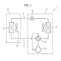
- An indoor unit configures an air conditioner 1 by being connected to an outdoor unit 3 by pipes 4, as shown in Fig. 1 .
- the air conditioner 1 has a refrigerant circuit.
- the refrigerant circuit has an indoor-side heat exchanger 10, a compressor 12, an outdoor-side heat exchanger 13, an expansion valve 14, and a four-way switch valve 15, as main configuration elements.
- the four-way switch valve 15 is switched so that a circulation direction in the refrigerant circuit is switched. In this way, in the air conditioner 1, a switchover between a cooling operation and a heating operation is performed.
- the indoor unit 2 is of a ceiling-suspended type (what is called a suspension type).
- the indoor unit 2 includes a casing 21 that is suspended from a ceiling by a suspension member such as a suspension bolt extended from the ceiling, and a decorative plate 22 fitted to a lower part of the casing 21, as shown in Fig. 2 and Fig. 3 .
- the casing 21 has an approximately square ceiling plate 23, and a sidewall 24 that is extended approximately downward from a peripheral edge of the ceiling plate 23.
- a blowout opening 25 is provided at approximately a center part in a horizontal direction.
- An airflow direction plate 25A is provided in the blowout opening 25.
- the airflow direction plate 25A changes a blowout direction of air after adjusting a temperature of the air blown out from the blowout opening 25.
- the airflow direction plate 25A is a rectangular plate-shaped member that is long in the horizontal direction.
- a swing motor not shown is connected to both end parts of the airflow direction plate 25A in the horizontal direction.
- the airflow direction plate 25A swings or turns by being driven by the swing motor.
- the decorative plate 22 has a rectangular suction grill 26 at a center part of the decorative plate 22.
- the indoor unit 2 has in the casing 21, a fan 27, a bell mouse 28, an air filter 29, the indoor-side heat exchanger 10, a drain pan 50, and a drain pump 60 (see Fig. 4 ).
- the fan 27 is a centrifugal fan (a turbofan) having an impeller 31 and a fan motor 32.
- the fan 27 is laid out such that an inlet port 33 of the fan 27 faces the suction grill 26 of the decorative plate 22.
- the fan 27 blows out air (indoor air and the like) taken in from the inlet port 33 at a lower side, toward sideways (toward the indoor-side heat exchanger 10).
- the bell mouse 28 is laid out between the inlet port 33 of the fan 27 and the suction grill 26.
- the air filter 29 has a size that covers an entrance of the bell mouse 28.
- the air filter 29 is laid out along the suction grill 26 between the bell mouse 28 and the suction grill 26.
- the indoor-side heat exchanger 10 has a plurality of thin-plate shaped fins 34 and a plurality of heat transfer tubes 35 that are pierced through through-holes formed in the plurality of thin-plate shaped fins 34.
- the indoor-side heat exchanger 10 is what is called a cross-fin type heat exchanger.
- the indoor-side heat exchanger 10 is laid out to surround the fan 27 (the impeller 31) from the horizontal direction.
- the indoor-side heat exchanger 10 performs a heat exchange between a refrigerant that flows in each heat transfer tube 35 and indoor air (outer air) that is blown out from the fan 27, via a tube wall of the heat transfer tube 35 and the fin 34.
- the drain pan 50 receives water drops generated in the indoor-side heat exchanger 10, and prevents the water drops from falling indoors.
- the drain pan 50 is laid out along the indoor-side heat exchanger 10 at the lower side of the indoor-side heat exchanger 10 (see Fig. 4 ).
- the drain pan 50 is formed in a shape of a substantial quadrilateral having a center part of the drain pan 50 opened (having an opening 51 at a position corresponding to the inlet port 33 of the fan 27) in the planar view, as shown in Fig. 5 to Fig. 9 .
- the drain pan 50 has a drain receiver 52 and a partition wall 54.
- the drain receiver 52 is configured by a groove (a recess) that is extended along the indoor-side heat exchanger 10.
- the drain receiver 52 receives, at the lower side of the indoor-side heat exchanger 10, the water generated on the surface of the indoor-side heat exchanger 10 on account of condensation of a water component in air.
- the drain pump 60 is laid out on a downstream end part (a terminal end, near an upper end at a left side in Fig. 5 and Fig. 6 ) of the drain receiver 52.
- the partition wall 54 is erected between both sidewalls (left and right sidewalls in Fig. 7 ) of the drain receiver 52 so as to be in contact with the indoor-side heat exchanger 10 from the lower side.
- the partition wall 54 partitions a space in the drain receiver (a groove) 52 into a region on a primary side and a region on a secondary side so as to form an inner groove 56 and an outer groove 58. That is, the partition wall 54 is a wall defined by a wall surface at an outer groove 58 side in the inner groove 56, and a wall surface at an inner groove 56 side in the outer groove 58.
- the region on the primary side is a region on an upstream side of the indoor-side heat exchanger 10 in the air flow w (see Fig. 3 ) blown out from the fan 27.
- the region on the secondary side is a region on a downstream side of the indoor-side heat exchanger 10 in the air flow w.
- the inner groove 56 is extended along the indoor-side heat exchanger 10, and receives in the region on the primary side, the water generated on the surface of the indoor-side heat exchanger 10. Specifically, the inner groove 56 is extended along each side of an approximately quadrangular drain pan 50 in the planar view, and is extended to surround the opening 51. In examples of Fig. 5 and Fig. 6 , by setting the vicinity of a left end of an upper side of the drain pan 50 as a start point, the inner groove 56 is extended clockwise along each side of the drain pan 50. The inner groove 56 is communicated to the outer groove 58 at an end point of extension (at the vicinity of an upper end of a left side) so that the inner groove 56 is continuous to the drain pump 60.
- a bottom 56a of the inner groove 56 is inclined to become a constant descending slope from the start point toward the drain pump 60. That is, at each position in a longitudinal direction of the inner groove 56, the water (drain) dropped from the indoor-side heat exchanger 10 flows in the inner groove 56 toward the drain pump 60.
- the outer groove 58 is extended along the indoor-side heat exchanger 10, and receives in the region on the secondary side, the water generated on the surface of the indoor-side heat exchanger 10.
- the bottom of the outer groove 58 is inclined to become a descending slope so that the drain flows toward the drain pump 60, in a similar manner to that of the inner groove 56.
- An inclination angle of the bottom of the outer groove 58 is larger than an inclination angle of the bottom 56a of the inner groove 56.
- the outer groove 58 is extended along the inner groove 56 at an outside (an opposite side of the opening 51 of the drain pan 50) of the inner groove 56. That is, the outer groove 58 is extended along each side of the approximately quadrangular drain pan 50 in the planar view, and is extended to surround the opening 51, at the outside of the inner groove 56.
- the outer groove 58 is partitioned into a plurality of sections in a longitudinal direction of the outer groove 58 (a flow direction of the water in the inner groove 56).
- the outer groove 58 according to the present embodiment is partitioned into four sections of a first section 581, a second section 582, a third section 583, and a fourth section 584.
- the outer groove 58 is partitioned at corners of the drain pan 50.
- a section along an upper side of the drain pan 50 shown in Fig. 5 and Fig. 6 is the first section 581
- a section along a right side is the second section 582
- a section along a lower side is the third section 583
- a section along a left side is the fourth section 584.
- the bottoms of the sections 581 to 584 are in descending slopes along a flow direction of the drain in the inner groove 56. That is, the bottom of the first section 581 is inclined so that a left end (a starting end) 581A in Fig. 6 is the highest and a right end (a terminating end) 581B is the lowest.
- the bottom of the second section 582 is inclined so that an upper end (a starting end) 582A in Fig. 6 is the highest and a lower end (a terminating end) 582B is the lowest.
- the bottom of the third section 583 is inclined so that a right end (a starting end) 583A in Fig. 6 is the highest and a left end (a terminating end) 583B is the lowest.
- the bottom of the fourth section 584 is inclined so that a lower end (a starting end) 584A in Fig. 6 is the highest and an upper end (a terminating end) 584B (specifically, a position where the drain pump 60 is laid out) is the lowest. Height positions of the bottoms of the starting ends 581A to 584A of the sections 581 to 584 are the same, and height positions of the bottoms of the terminating ends 581B to 584B of the sections 581 to 584 are the same.
- a height difference is provided between a height of the bottom at the terminating end of a section at the upstream side (the terminating end 582B of the second section 582, for example) and a height position of the bottom at the starting end of a section at the downstream side (the starting end 583A of the third section 583, for example).
- a positioner 59 for determining a position in the horizontal direction of the indoor-side heat exchanger 10 relative to the drain pan 50 by contacting to a side portion of the indoor-side heat exchanger 10 is formed between adjacent sections.
- the positioner 59 is stretched upward from a bottom position of a terminating end of a section at the upstream side (the terminating end 582B of the second section 582, for example), between adjacent sections (between the second section 582 and the third section 583, for example) so as to divide the outer groove 58 into the sections 581 to 584.
- a height difference is formed between a height of the bottom at the terminating end of a section at the upstream side (the terminating end 582B of the second section 582, for example) and a height of the bottom at the starting end of a section at the downstream side (the starting end 583A of the third section 583, for example) adjacent to the upstream section.
- Height positions of the starting ends 581A to 583A of the first to third sections 581 to 583 are set so that height positions of the bottoms of the terminating ends 581B to 583B of the first to third sections 581 to 583 become the same as or higher than height positions of the bottoms of portions of the inner groove 56 (portions that are communicated by communicating parts 540 described later) corresponding to the terminating ends 581B to 583B.
- the inclination angles of the bottoms of the sections 581 to 584 change at an intermediate part in the longitudinal direction. That is, in the bottoms of the sections 581 to 584, the inclination angles of portions at sides of the starting ends 581A to 584A are different from the inclination angles of portions at sides of the terminating ends 581B to 584B. That is, the inclination angles of portions from a longitudinal-direction center to the terminating ends 581B to 584B in the bottoms of the sections 581 to 584 are the same as the inclination angle of the bottom 56a of the inner groove 56.
- the inclination angles of portions from the starting ends 581A to 584A to the longitudinal-direction center in the bottoms of the sections 581 to 584 are larger than the inclination angle of the bottom 56a of the inner groove 56. Therefore, the average inclination angle of each of the bottoms of the sections 581 to 584 is larger than the inclination angle of the bottom 56a of the inner groove 56.
- the inclination angle of the bottom is the average inclination angle of the entire region of the outer groove 58 between the starting end 581A and the terminating end 584B.
- the average inclination angle is larger than the inclination angle of the bottom 56a of the inner groove 56.
- the inclination angle of the bottom 56a of the inner groove 56 may be also the average inclination angle between the starting end 56A and the terminating end 56B of the inner groove 56.
- a thickness of the drain pan 50 can be suppressed while providing a steep slope in the inclination of the bottom of the outer groove 58 (the sections 581 to 584).
- the communicating parts 540 that communicate between the outer groove 58 and the inner groove 56 are provided in the partition wall 54 and positioned corresponding to the terminating ends 581B to 584B of the sections 581 to 584.
- Each communicating part 540 is a portion in which the drain flows from the outer groove 58 to the inner groove 56 or from the inner groove 56 to the outer groove 58.
- the communicating part 540 is a groove (see Fig. 8 ) provided to cross the partition wall 54.
- the communicating part 540 is not limited to the groove and may be a through-hole that communicates between the outer groove 58 and the inner groove 56.
- the terminating ends 581B to 583B of the first to third sections 581 to 583 are formed at corners of the drain pan 50 (that is, the corners of the casing 21 of the indoor unit 2 at positions deviated from a front position of the blowout openings 25). Therefore, the communicating parts 540 provided at positions corresponding to the terminating ends 581B to 583B are also provided at the corners of the drain pan 50.
- Straight line portions 53 at peripheral parts of the drain pan 50 are portions that define the lower ends of the blowout openings 25 of the indoor unit 2 (see Fig. 3 ).
- the bottoms of the outer groove 58 and the bottoms of the communicating parts 540 integrally configure inclination surfaces of descending slopes toward the inner groove 56. Accordingly, the drain that flows from the sides of the starting ends 581A to 583A does not stay for a long time in the terminating ends 581B to 583B of the first to third sections 581 to 583, and securely flows into the inner groove 56.
- the drain pump 60 is laid out at the terminating end 584B of the fourth section 584.
- the drain that flows in the inner groove 56 (including the drain that flows in the first to third sections 581 to 583 and flows into the inner groove 56) flows into the terminating end 584B of the fourth section 584 through the communicating part 540 (see Fig. 9 ) that communicates between the terminating end 56B of the inner groove 56 and the terminating end 584B of the fourth section 584.
- the drain pump 60 has a pump body 61 and a water level sensor 62.
- the pump body 61 is driven to discharge the drain to an outside of the indoor unit 2.
- the drain that flows in the outer groove 58 can flow into the inner groove 56 through the communicating parts 540 on the way to the drain pump 60. Therefore, a stay time of the drain in the outer groove 58 becomes even shorter, and scattering of the drain in the outer groove 58 to the outside of the indoor unit 2 can be more securely prevented.
- the height position of the bottom of the outer groove 58 is the same as or higher than the height position of the bottom of the inner groove 56. Therefore, when the drain that flows in the outer groove 58 arrives at the positions of the communicating parts 540, the drain flows from the outer groove 58 into the inner groove 56 through the communicating parts 540. Accordingly, a distance over which the drain flows in the outer groove 58 becomes short, and the stay time of the drain in the outer groove 58 becomes even shorter.
- the communicating parts 540 are provided at positions deviated from the front position of the blowout opening 25 of the indoor unit 2, the air that passed through the communicating parts 540 is not easily blown out from the blowout opening 25 as compared with a case where the communicating parts 540 are provided at the front position. Therefore, a flow rate of the air blown out from the region on the primary side through the communicating parts 540 to the region on the secondary side can be suppressed. As a result, scattering of the drain in the outer groove 58 and the communicating parts 540 to the outside of the indoor unit 2 by the airflow can be suppressed.
- the distance over which the drain can flow in the outer groove 58 is shortened. That is, in the indoor unit 2 according to the present embodiment, by partitioning the outer groove 58 into the plurality of sections 581 to 584, the stay time of the drain in the outer groove 58 is made shorter. Accordingly, scattering of the drain from the outer groove 58 to the outside of the indoor unit 2 can be more securely prevented.
- the outer groove 58 By partitioning the outer groove 58 into the plurality of sections 581 to 584, the outer groove 58 can be laid out in a serrated shape having a height difference provided between the height of the terminating end of a section at the upstream side (the terminating end 582B of the second section 582, for example) and the height of the starting end of a section at the downstream side (the starting end 583A of the third section 583, for example) as an adjacent section. Accordingly, a thickness of the drain pan 50 can be suppressed while providing a steep slope in the inclination of the bottom of the outer groove 58 (the sections 581 to 582).
- the communicating parts 540 are provided at lower end positions (the terminating ends 581B to 583B) of the first to third sections 581 to 583, respectively, the drain that flowed in the sections 581 to 583 all flows into the inner groove 56 through the communicating parts 540. Therefore, a long-time stay of the drain in the outer groove 58 can be prevented.
- the indoor unit for the air conditioner according to the present invention is not limited to the above embodiment, and can be variously modified within a range not deviating from the gist of the present invention.
- the communicating parts 540 are laid out at positions (the corners of the indoor unit 2) deviated from the front position of the opening 25 of the indoor unit 2 in the horizontal direction.
- the layout positions of the communicating parts 540 are not limited to these positions.
- the communicating parts 540 may be provided at the front position of the opening 25 in the horizontal direction.
- the communicating parts 540 are provided at a position lower than the opening 25. Accordingly, the flow rate of the air that flows from the region on the primary side to the region on the secondary side through the communicating parts 540 can be suppressed, and scattering of the drain to the outside by the airflow can be suppressed.
- the communicating parts 540 are provided at only the positions 581B to 584B where the bottoms of the outer groove 58 (the sections 581 to 584) are the lowest.
- the communicating parts 540 are not limited to this configuration.
- the communicating parts 540 may be provided at intermediate positions in the height direction in addition to the lowest positions. Even when the communicating parts 540 are provided at the intermediate positions, the drain that flows in the outer groove 58 can also flow into the inner groove 56 through the communicating parts 540, and the distance over which the drain flows in the outer groove 58 can be shortened.
- inclination angles of the bottoms of the sections 581 to 584 change in the middle of the length direction.
- the inclination angles are not limited to this configuration.
- the inclination angles of the bottoms from the starting ends 581A to 584A to the terminating ends 581B to 584B may be constant.
- the four (the plurality of) communicating parts 540 are provided.
- the communicating parts 540 are not limited to this configuration.
- One communicating part 540 may be provided at the most downstream end (a terminal end) of the inner groove 56 or the outer groove 58, with the outer groove 58 not being partitioned (segmented). That is, the inner groove 56 and the outer groove 58 may be communicated at only the vicinity of the layout position of the drain pump 60.
- the communicating parts 540 may not be provided.
- the drain pumps 60 are provided in the terminating end of the inner groove 56 and in the terminating end of the outer groove 58, respectively.
- the indoor unit 2 according to the present embodiment is of a ceiling-suspended type
- the indoor unit may be a ceiling-embedded type (what is called a cassette type). That is, in the indoor unit 2 according to the present embodiment, although the blowout opening 25 is formed on a side surface, the blowout opening may be formed on a bottom surface.
- the inner groove 56 and the outer groove 58 are formed by providing the partition wall 54 in the drain receiver 52, and the inclination angle of the bottom of the outer groove 58 is set larger than the inclination angle of the bottom of the inner groove 56. Accordingly, a rise in the water level in the region on the secondary side (the outer groove 58) of the drain receiver 52 can be securely prevented. Further, by shortening the stay time of the drain in the region on the secondary side (the outer groove 58) by quickly passing the drain received by the outer groove 58 to the drain pump 60 side, scattering of the drain to the outside of the indoor unit can be prevented.
- the indoor unit 2 blows out air to four directions
- the indoor unit 2 is not limited to this configuration.
- the indoor unit may blow out air to two directions, or to one direction.
- the indoor unit 2 is used for the air conditioner 1 that performs both a cooling operation and a heating operation, the indoor unit 2 is not limited to this configuration.
- the indoor unit may be exclusively used for a cooling air conditioner or may be exclusively used for a heating air conditioner.
- an indoor unit for an air conditioner includes a heat exchanger, a drain pan laid out at a lower side of the heat exchanger, and a drain pump that discharges water collected in the drain pan to an outside.
- the drain pan includes a drain receiver that is extended along the heat exchanger and that receives the water generated on a surface of the heat exchanger, at the lower side of the heat exchanger, and a partition wall that is erected to be in contact with the heat exchanger from a lower side and that partitions an inside of the drain receiver into a region on an upstream side and a region on a downstream side of an airflow so as to form an inner groove which receives the water in the region on the upstream side of the airflow and an outer groove which receives the water in the region on the downstream side of the airflow.
- a bottom of the outer groove and a bottom of the inner groove have respectively inclinations which are descending slopes where the water flows toward the drain pump.
- An average inclination angle of the bottom of the outer groove is larger than an inclination angle
- the drain receiver a rise in the water level in the region on the secondary side (the outer groove) can be securely prevented.
- the slope of the bottom surface of the outer groove can be set steeper than the slope of the bottom surface of the inner groove. Accordingly, by quickly passing the water (the drain) received by the outer groove to the drain pump side, the stay time of the drain in the region on the secondary side (the outer groove) can be shortened. As a result, scattering of the drain to the outside of the indoor unit can be effectively prevented.
- the partition wall may have one or a plurality of communicating parts that communicate between the outer groove and the inner groove.
- a height position of the bottom of the outer groove at a position of the communicating part may be the same as or higher than a height position of the bottom of the inner groove at the position of the communicating part.
- the communicating part may be provided at a position deviated from a front position of the blowout opening of air in the indoor unit.
- the drain that flows in the outer groove can flow into the inner groove through the communicating parts on the way to the drain pump. Therefore, the stay time of the drain in the outer groove becomes shorter. As a result, scattering of the drain in the outer groove to the outside of the indoor unit can be more securely prevented.
- the height position of the bottom of the outer groove becomes the same as or higher than the height position of the bottom of the inner groove. Therefore, when the drain that flows in the outer groove arrives at the positions of the communicating parts, the drain flows from the outer groove into the inner groove through the communicating parts. Accordingly, a distance over which the drain flows in the outer groove becomes short, and the stay time of the drain in the outer groove becomes shorter.
- the communicating parts are provided at positions deviated from the front position of the blowout opening of the indoor unit, a pressure loss from when the air passed through the communicating parts till when the air is blown out from the blowout opening increases as compared with a case where the communicating parts are provided at the front position. Accordingly, a flow rate of the air blown out from the region on the primary side to the region on the secondary side through the communicating parts is suppressed. As a result, scattering of the drain in the outer groove and the inner groove to the outside of the indoor unit by the airflow can be suppressed.
- the outer groove may be partitioned into a plurality of sections in the longitudinal direction of the outer groove.
- the communicating part may be provided at a lower end position which is the lowest part of the bottom in each section of the outer groove.
- the outer groove By partitioning the outer groove into a plurality of sections, the outer groove can be laid out in a serrated shape having a height difference provided between the height of the terminating end of a section at the upstream side and the height of the starting end of a section at the downstream side as an adjacent section. Accordingly, a thickness of the drain pan can be suppressed while providing a steep slope in the inclination of the bottom of the outer groove (each section).
- the communicating parts are provided at lower end positions of the respective sections, the drain that flowed in the sections all flows into the inner groove through the communicating parts. Therefore, a long-time stay of the drain in the outer groove can be prevented.
- the partition wall may have one or a plurality of communicating parts that communicate between the outer groove and the inner groove.
- the outer groove may be partitioned into a plurality of sections in the longitudinal direction of the outer groove.
- a height position of the bottom of the outer groove at a position of the communicating part may be the same as or higher than a height position of the bottom of the inner groove at the position of the communicating part.
- the communicating parts may be provided at a lower end position which is the lowest part of the bottom in each section of the outer groove.
- the outer groove By partitioning the outer groove into a plurality of sections, the outer groove can be laid out in a serrated shape having a height difference provided between the height of the terminating end of a section at the upstream side and the height of the starting end of a section at the downstream side as an adjacent section. Accordingly, a thickness of the drain pan can be suppressed while providing a steep slope in the inclination of the bottom of the outer groove (each section).
- the communicating parts are provided at lower end positions of the respective sections, the drain that flowed in the sections all flows into the inner groove through the communicating parts. Therefore, a long-time stay of the drain in the outer groove can be prevented.
- the bottom of the outer groove may have an inclination which is a descending slope from the outer groove toward the inner groove, at the position of the communicating part.
- the drain that flowed in the outer groove (each section) more securely flows into the inner groove through the communicating part.
- the indoor unit for the air conditioner may include a fan that blows out air taken in from a lower side toward sideways, and one or a plurality of blowout openings for blowing out the air to an outside.
- the heat exchanger may be formed in a shape of a substantial quadrilateral in a planar view and laid out to surround the fan from a horizontal direction.
- the blowout openings may be located on opposite sides of the fan with respect to the heat exchanger, and provided at positions corresponding to sides of the substantial quadrilateral.
- the communicating parts may be provided at positions corresponding to corners of the substantial quadrilateral.
- the present invention can be utilized as an indoor unit for an air conditioner.
Landscapes
- Engineering & Computer Science (AREA)
- Chemical & Material Sciences (AREA)
- Combustion & Propulsion (AREA)
- Mechanical Engineering (AREA)
- General Engineering & Computer Science (AREA)
- Physics & Mathematics (AREA)
- Thermal Sciences (AREA)
- Devices For Blowing Cold Air, Devices For Blowing Warm Air, And Means For Preventing Water Condensation In Air Conditioning Units (AREA)
Abstract
Description
- The present invention relates to an indoor unit for an air conditioner that performs a vapor-compression refrigerating cycle by circulating a refrigerant.
-
Patent Document 1 discloses an indoor unit for an air conditioner. As shown inFig. 10 andFig. 11 , the indoor unit includes afan 102, aheat exchanger 104 that cools or heats air from thefan 102, adrain pan 106 laid out at a lower side of theheat exchanger 104, and adrain pump 108 that discharges water (drain) collected in thedrain pan 106 to an outside of anindoor unit 100. - The
drain pan 106 has adrain receiver 107 that receives, at the lower side of theheat exchanger 104, water generated on a surface of theheat exchanger 104 on account of condensation of a water component in air. Thedrain receiver 107 is formed to stride over an upstream side (a primary side) of theheat exchanger 104 in an air flow direction w by thefan 102 and a downstream side (a secondary side) in the air flow direction w, at the lower side of theheat exchanger 104. A bottom surface 17A of thedrain receiver 107 has a descending slope toward the drain pump 108 (seeFig. 11 ). With this layout, the water (the water generated on the surface of the heat exchanger 104) received by thedrain receiver 107 is collected in thedrain pump 108. When thedrain pump 108 drains the collected water (drain), the drain is efficiently discharged from thedrain pan 106. - In the
indoor unit 100, a pressure at the primary side becomes higher than a pressure at the secondary side inside theindoor unit 100 by an air flow w by thefan 102 at an operation time. Therefore, a water level (a water surface) of the drain inside thedrain receiver 107 at the secondary side becomes higher than at the primary side (seeFig. 10 ). - When the water level at the secondary side becomes higher in this way, waves are generated in the drain by the air flow w at the secondary side, and a part of the drain has a risk of being scattered from a blowout opening 109 of the
indoor unit 100 to the outside of theindoor unit 100. - Patent Document 1: Japanese Patent Application Laid-open No.
2007-255739 - An object of the present invention is to provide an indoor unit for an air conditioner in which water is not easily scattered from a drain pan to the outside by blast of air.
- According to one aspect of the present invention, an indoor unit for an air conditioner includes a heat exchanger, a drain pan laid out at a lower side of the heat exchanger, and a drain pump that discharges water collected in the drain pan to an outside. The drain pan includes a drain receiver that is extended along the heat exchanger and that receives the water generated on a surface of the heat exchanger, at the lower side of the heat exchanger, and a partition wall that is erected to be in contact with the heat exchanger from a lower side and that partitions an inside of the drain receiver into an upstream side and a downstream side of an airflow so as to form an inner groove which receives the water on the upstream side of the airflow and an outer groove which receives the water on the downstream side of the airflow. A bottom of the outer groove and a bottom of the inner groove have respectively inclinations which are descending slopes where the water flows toward the drain pump. An inclination angle of the bottom of the outer groove is larger than an inclination angle of the bottom of the inner groove.
-
-
Fig. 1 is a schematic configuration diagram of an air conditioner according to the present embodiment. -
Fig. 2 is perspective view of an indoor unit for the air conditioner. -
Fig. 3 is a longitudinal sectional view of the indoor unit. -
Fig. 4 is a plan view showing a layout of a heat exchanger and a drain pan in the indoor unit. -
Fig. 5 is a plan view of the drain pan. -
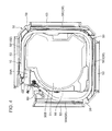
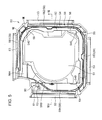
Fig. 6 shows positions of an inner groove, an outer groove and a communication part in the drain pan. -
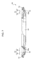
Fig. 7 is a sectional view at a position along a line VII-VII inFig. 5 . -
Fig. 8 is an enlarged end view at a position along a line VIII-VIII inFig. 5 . -
Fig. 9 a partially enlarged view in a state that the heat exchanger is laid out on the drain pan. -
Fig. 10 is a longitudinal sectional view in a width direction of the indoor unit for a conventional air conditioner. -
Fig. 11 is a longitudinal sectional view in a length direction (a direction orthogonal with the width direction) of the indoor unit for the conventional air conditioner. - An embodiment of the present invention will be described below with reference to the appended drawings.
- An indoor unit according to the present embodiment (hereinafter, "indoor unit") configures an
air conditioner 1 by being connected to anoutdoor unit 3 bypipes 4, as shown inFig. 1 . Theair conditioner 1 has a refrigerant circuit. The refrigerant circuit has an indoor-side heat exchanger 10, acompressor 12, an outdoor-side heat exchanger 13, anexpansion valve 14, and a four-way switch valve 15, as main configuration elements. In theair conditioner 1, the four-way switch valve 15 is switched so that a circulation direction in the refrigerant circuit is switched. In this way, in theair conditioner 1, a switchover between a cooling operation and a heating operation is performed. - The
indoor unit 2 is of a ceiling-suspended type (what is called a suspension type). Theindoor unit 2 includes acasing 21 that is suspended from a ceiling by a suspension member such as a suspension bolt extended from the ceiling, and adecorative plate 22 fitted to a lower part of thecasing 21, as shown inFig. 2 andFig. 3 . Thecasing 21 has an approximatelysquare ceiling plate 23, and asidewall 24 that is extended approximately downward from a peripheral edge of theceiling plate 23. On a portion of thesidewall 24 corresponding to each side of theceiling plate 23, ablowout opening 25 is provided at approximately a center part in a horizontal direction. Anairflow direction plate 25A is provided in the blowout opening 25. Theairflow direction plate 25A changes a blowout direction of air after adjusting a temperature of the air blown out from the blowout opening 25. Theairflow direction plate 25A is a rectangular plate-shaped member that is long in the horizontal direction. A swing motor not shown is connected to both end parts of theairflow direction plate 25A in the horizontal direction. Theairflow direction plate 25A swings or turns by being driven by the swing motor. Thedecorative plate 22 has arectangular suction grill 26 at a center part of thedecorative plate 22. - The
indoor unit 2 has in thecasing 21, afan 27, abell mouse 28, anair filter 29, the indoor-side heat exchanger 10, adrain pan 50, and a drain pump 60 (seeFig. 4 ). - The
fan 27 is a centrifugal fan (a turbofan) having animpeller 31 and afan motor 32. Thefan 27 is laid out such that aninlet port 33 of thefan 27 faces thesuction grill 26 of thedecorative plate 22. Thefan 27 blows out air (indoor air and the like) taken in from theinlet port 33 at a lower side, toward sideways (toward the indoor-side heat exchanger 10). Thebell mouse 28 is laid out between theinlet port 33 of thefan 27 and thesuction grill 26. - The
air filter 29 has a size that covers an entrance of thebell mouse 28. Theair filter 29 is laid out along thesuction grill 26 between thebell mouse 28 and thesuction grill 26. - The indoor-
side heat exchanger 10 has a plurality of thin-plate shapedfins 34 and a plurality ofheat transfer tubes 35 that are pierced through through-holes formed in the plurality of thin-plate shapedfins 34. The indoor-side heat exchanger 10 is what is called a cross-fin type heat exchanger. The indoor-side heat exchanger 10 is laid out to surround the fan 27 (the impeller 31) from the horizontal direction. The indoor-side heat exchanger 10 performs a heat exchange between a refrigerant that flows in eachheat transfer tube 35 and indoor air (outer air) that is blown out from thefan 27, via a tube wall of theheat transfer tube 35 and thefin 34. - The
drain pan 50 receives water drops generated in the indoor-side heat exchanger 10, and prevents the water drops from falling indoors. Thedrain pan 50 is laid out along the indoor-side heat exchanger 10 at the lower side of the indoor-side heat exchanger 10 (seeFig. 4 ). - Specifically, the
drain pan 50 is formed in a shape of a substantial quadrilateral having a center part of thedrain pan 50 opened (having anopening 51 at a position corresponding to theinlet port 33 of the fan 27) in the planar view, as shown inFig. 5 to Fig. 9 . Thedrain pan 50 has adrain receiver 52 and apartition wall 54. - The
drain receiver 52 is configured by a groove (a recess) that is extended along the indoor-side heat exchanger 10. Thedrain receiver 52 receives, at the lower side of the indoor-side heat exchanger 10, the water generated on the surface of the indoor-side heat exchanger 10 on account of condensation of a water component in air. Thedrain pump 60 is laid out on a downstream end part (a terminal end, near an upper end at a left side inFig. 5 andFig. 6 ) of thedrain receiver 52. - The
partition wall 54 is erected between both sidewalls (left and right sidewalls inFig. 7 ) of thedrain receiver 52 so as to be in contact with the indoor-side heat exchanger 10 from the lower side. Thepartition wall 54 partitions a space in the drain receiver (a groove) 52 into a region on a primary side and a region on a secondary side so as to form aninner groove 56 and anouter groove 58. That is, thepartition wall 54 is a wall defined by a wall surface at anouter groove 58 side in theinner groove 56, and a wall surface at aninner groove 56 side in theouter groove 58. The region on the primary side is a region on an upstream side of the indoor-side heat exchanger 10 in the air flow w (seeFig. 3 ) blown out from thefan 27. The region on the secondary side is a region on a downstream side of the indoor-side heat exchanger 10 in the air flow w. - The
inner groove 56 is extended along the indoor-side heat exchanger 10, and receives in the region on the primary side, the water generated on the surface of the indoor-side heat exchanger 10. Specifically, theinner groove 56 is extended along each side of an approximatelyquadrangular drain pan 50 in the planar view, and is extended to surround theopening 51. In examples ofFig. 5 andFig. 6 , by setting the vicinity of a left end of an upper side of thedrain pan 50 as a start point, theinner groove 56 is extended clockwise along each side of thedrain pan 50. Theinner groove 56 is communicated to theouter groove 58 at an end point of extension (at the vicinity of an upper end of a left side) so that theinner groove 56 is continuous to thedrain pump 60. A bottom 56a of theinner groove 56 is inclined to become a constant descending slope from the start point toward thedrain pump 60. That is, at each position in a longitudinal direction of theinner groove 56, the water (drain) dropped from the indoor-side heat exchanger 10 flows in theinner groove 56 toward thedrain pump 60. - The
outer groove 58 is extended along the indoor-side heat exchanger 10, and receives in the region on the secondary side, the water generated on the surface of the indoor-side heat exchanger 10. The bottom of theouter groove 58 is inclined to become a descending slope so that the drain flows toward thedrain pump 60, in a similar manner to that of theinner groove 56. An inclination angle of the bottom of theouter groove 58 is larger than an inclination angle of the bottom 56a of theinner groove 56. - Specifically, the
outer groove 58 is extended along theinner groove 56 at an outside (an opposite side of theopening 51 of the drain pan 50) of theinner groove 56. That is, theouter groove 58 is extended along each side of the approximatelyquadrangular drain pan 50 in the planar view, and is extended to surround theopening 51, at the outside of theinner groove 56. - The
outer groove 58 is partitioned into a plurality of sections in a longitudinal direction of the outer groove 58 (a flow direction of the water in the inner groove 56). Theouter groove 58 according to the present embodiment is partitioned into four sections of afirst section 581, asecond section 582, athird section 583, and afourth section 584. Specifically, theouter groove 58 is partitioned at corners of thedrain pan 50. In theouter groove 58 according to the present embodiment, a section along an upper side of thedrain pan 50 shown inFig. 5 andFig. 6 is thefirst section 581, a section along a right side is thesecond section 582, a section along a lower side is thethird section 583, and a section along a left side is thefourth section 584. - The bottoms of the
sections 581 to 584 are in descending slopes along a flow direction of the drain in theinner groove 56. That is, the bottom of thefirst section 581 is inclined so that a left end (a starting end) 581A inFig. 6 is the highest and a right end (a terminating end) 581B is the lowest. The bottom of thesecond section 582 is inclined so that an upper end (a starting end) 582A inFig. 6 is the highest and a lower end (a terminating end) 582B is the lowest. The bottom of thethird section 583 is inclined so that a right end (a starting end) 583A inFig. 6 is the highest and a left end (a terminating end) 583B is the lowest. The bottom of thefourth section 584 is inclined so that a lower end (a starting end) 584A inFig. 6 is the highest and an upper end (a terminating end) 584B (specifically, a position where thedrain pump 60 is laid out) is the lowest. Height positions of the bottoms of the starting ends 581A to 584A of thesections 581 to 584 are the same, and height positions of the bottoms of the terminating ends 581B to 584B of thesections 581 to 584 are the same. That is, in adjacent sections (thesecond section 582 and thethird section 583, for example), a height difference is provided between a height of the bottom at the terminating end of a section at the upstream side (the terminatingend 582B of thesecond section 582, for example) and a height position of the bottom at the starting end of a section at the downstream side (the startingend 583A of thethird section 583, for example). - In the
drain pan 50 according to the present embodiment, apositioner 59 for determining a position in the horizontal direction of the indoor-side heat exchanger 10 relative to thedrain pan 50 by contacting to a side portion of the indoor-side heat exchanger 10 is formed between adjacent sections. Thepositioner 59 is stretched upward from a bottom position of a terminating end of a section at the upstream side (the terminatingend 582B of thesecond section 582, for example), between adjacent sections (between thesecond section 582 and thethird section 583, for example) so as to divide theouter groove 58 into thesections 581 to 584. By using thepositioner 59, a height difference is formed between a height of the bottom at the terminating end of a section at the upstream side (the terminatingend 582B of thesecond section 582, for example) and a height of the bottom at the starting end of a section at the downstream side (the startingend 583A of thethird section 583, for example) adjacent to the upstream section. Height positions of the starting ends 581A to 583A of the first tothird sections 581 to 583 are set so that height positions of the bottoms of the terminating ends 581B to 583B of the first tothird sections 581 to 583 become the same as or higher than height positions of the bottoms of portions of the inner groove 56 (portions that are communicated by communicatingparts 540 described later) corresponding to the terminating ends 581B to 583B. - The inclination angles of the bottoms of the
sections 581 to 584 change at an intermediate part in the longitudinal direction. That is, in the bottoms of thesections 581 to 584, the inclination angles of portions at sides of the starting ends 581A to 584A are different from the inclination angles of portions at sides of the terminating ends 581B to 584B. That is, the inclination angles of portions from a longitudinal-direction center to the terminating ends 581B to 584B in the bottoms of thesections 581 to 584 are the same as the inclination angle of the bottom 56a of theinner groove 56. The inclination angles of portions from the starting ends 581A to 584A to the longitudinal-direction center in the bottoms of thesections 581 to 584 are larger than the inclination angle of the bottom 56a of theinner groove 56. Therefore, the average inclination angle of each of the bottoms of thesections 581 to 584 is larger than the inclination angle of the bottom 56a of theinner groove 56. By setting the inclination angles of the bottoms of the portions at the sides of the starting ends 581A to 584A larger than at the longitudinal-direction center in this way, the drain received in the portions at the sides of the starting ends 581A to 584A can be pushed in flow in a strong current toward the terminating ends 581B to 584B. Based on this flow, the drain in the portions from the longitudinal-direction center to the terminating ends 581B to 584B is pushed and flowed to the terminating ends 581B to 584B. - In the
outer groove 58 according to the present embodiment, the inclination angle of the bottom is the average inclination angle of the entire region of theouter groove 58 between the startingend 581A and the terminatingend 584B. The average inclination angle is larger than the inclination angle of the bottom 56a of theinner groove 56. The inclination angle of the bottom 56a of theinner groove 56 may be also the average inclination angle between the startingend 56A and the terminatingend 56B of theinner groove 56. - As described above, by arranging the
outer groove 58 in a serrated shape, by partitioning theouter groove 58 in the longitudinal direction (a flow direction of the water in the inner groove 56) and also by providing a height difference between the height of the terminating end of a section at the upstream side (the terminatingend 582B of thesecond section 582, for example) and the height of the starting end of a section at the downstream side (the startingend 583A of thethird section 583, for example) as an adjacent section, a thickness of thedrain pan 50 can be suppressed while providing a steep slope in the inclination of the bottom of the outer groove 58 (thesections 581 to 584). - The communicating
parts 540 that communicate between theouter groove 58 and theinner groove 56 are provided in thepartition wall 54 and positioned corresponding to the terminating ends 581B to 584B of thesections 581 to 584. Each communicatingpart 540 is a portion in which the drain flows from theouter groove 58 to theinner groove 56 or from theinner groove 56 to theouter groove 58. The communicatingpart 540 is a groove (seeFig. 8 ) provided to cross thepartition wall 54. The communicatingpart 540 is not limited to the groove and may be a through-hole that communicates between theouter groove 58 and theinner groove 56. - In the present embodiment, the terminating ends 581B to 583B of the first to
third sections 581 to 583 are formed at corners of the drain pan 50 (that is, the corners of thecasing 21 of theindoor unit 2 at positions deviated from a front position of the blowout openings 25). Therefore, the communicatingparts 540 provided at positions corresponding to the terminating ends 581B to 583B are also provided at the corners of thedrain pan 50.Straight line portions 53 at peripheral parts of thedrain pan 50 are portions that define the lower ends of theblowout openings 25 of the indoor unit 2 (seeFig. 3 ). - At the terminating ends 581B to 583B of the first to
third sections 581 to 583, the bottoms of theouter groove 58 and the bottoms of the communicatingparts 540 integrally configure inclination surfaces of descending slopes toward theinner groove 56. Accordingly, the drain that flows from the sides of the starting ends 581A to 583A does not stay for a long time in the terminating ends 581B to 583B of the first tothird sections 581 to 583, and securely flows into theinner groove 56. - The
drain pump 60 is laid out at the terminatingend 584B of thefourth section 584. The drain that flows in the inner groove 56 (including the drain that flows in the first tothird sections 581 to 583 and flows into the inner groove 56) flows into the terminatingend 584B of thefourth section 584 through the communicating part 540 (seeFig. 9 ) that communicates between the terminatingend 56B of theinner groove 56 and the terminatingend 584B of thefourth section 584. - The
drain pump 60 has apump body 61 and awater level sensor 62. In thedrain pump 60, when thewater level sensor 62 detects that the drain collected in the terminatingend 584B of the fourth section 584 (the terminating end of the outer groove 58) reaches a predetermined water level, thepump body 61 is driven to discharge the drain to an outside of theindoor unit 2. - In the
indoor unit 2, move of the drain in thedrain receiver 52 to the region on the primary side (that is, the move from theinner groove 56 to the outer groove 58) by a pressure difference between the pressure in the region on the primary side and the pressure in the region on the secondary side is blocked by providing thepartition wall 54 in thedrain pan 50. Accordingly, a rise in the water level in the region on the secondary side (the outer groove 58) of thedrain receiver 52 can be securely prevented. Further, by setting the slope of the bottom of theouter groove 58 to be steeper than the slope of the bottom of theinner groove 56, the drain received by theouter groove 58 can be quickly passed to thedrain pump 60 side. Accordingly, by shortening a stay time of the drain in the region on the secondary side (the outer groove 58), scattering of the drain to the outside of theindoor unit 2 can be effectively prevented. - In the
indoor unit 2 according to the present embodiment, the drain that flows in theouter groove 58 can flow into theinner groove 56 through the communicatingparts 540 on the way to thedrain pump 60. Therefore, a stay time of the drain in theouter groove 58 becomes even shorter, and scattering of the drain in theouter groove 58 to the outside of theindoor unit 2 can be more securely prevented. Specifically, at positions where the communicatingparts 540 are provided, the height position of the bottom of theouter groove 58 is the same as or higher than the height position of the bottom of theinner groove 56. Therefore, when the drain that flows in theouter groove 58 arrives at the positions of the communicatingparts 540, the drain flows from theouter groove 58 into theinner groove 56 through the communicatingparts 540. Accordingly, a distance over which the drain flows in theouter groove 58 becomes short, and the stay time of the drain in theouter groove 58 becomes even shorter. - Because the communicating
parts 540 are provided at positions deviated from the front position of the blowout opening 25 of theindoor unit 2, the air that passed through the communicatingparts 540 is not easily blown out from theblowout opening 25 as compared with a case where the communicatingparts 540 are provided at the front position. Therefore, a flow rate of the air blown out from the region on the primary side through the communicatingparts 540 to the region on the secondary side can be suppressed. As a result, scattering of the drain in theouter groove 58 and the communicatingparts 540 to the outside of theindoor unit 2 by the airflow can be suppressed. - In the
indoor unit 2 according to the present embodiment, by partitioning theouter groove 58 into the plurality ofsections 581 to 584, the distance over which the drain can flow in theouter groove 58 is shortened. That is, in theindoor unit 2 according to the present embodiment, by partitioning theouter groove 58 into the plurality ofsections 581 to 584, the stay time of the drain in theouter groove 58 is made shorter. Accordingly, scattering of the drain from theouter groove 58 to the outside of theindoor unit 2 can be more securely prevented. - By partitioning the
outer groove 58 into the plurality ofsections 581 to 584, theouter groove 58 can be laid out in a serrated shape having a height difference provided between the height of the terminating end of a section at the upstream side (the terminatingend 582B of thesecond section 582, for example) and the height of the starting end of a section at the downstream side (the startingend 583A of thethird section 583, for example) as an adjacent section. Accordingly, a thickness of thedrain pan 50 can be suppressed while providing a steep slope in the inclination of the bottom of the outer groove 58 (thesections 581 to 582). - Because the communicating
parts 540 are provided at lower end positions (the terminating ends 581B to 583B) of the first tothird sections 581 to 583, respectively, the drain that flowed in thesections 581 to 583 all flows into theinner groove 56 through the communicatingparts 540. Therefore, a long-time stay of the drain in theouter groove 58 can be prevented. - The indoor unit for the air conditioner according to the present invention is not limited to the above embodiment, and can be variously modified within a range not deviating from the gist of the present invention.
- In the
outdoor unit 2 according to the present embodiment, the communicatingparts 540 are laid out at positions (the corners of the indoor unit 2) deviated from the front position of theopening 25 of theindoor unit 2 in the horizontal direction. However, the layout positions of the communicatingparts 540 are not limited to these positions. For example, the communicatingparts 540 may be provided at the front position of theopening 25 in the horizontal direction. In this case, the communicatingparts 540 are provided at a position lower than theopening 25. Accordingly, the flow rate of the air that flows from the region on the primary side to the region on the secondary side through the communicatingparts 540 can be suppressed, and scattering of the drain to the outside by the airflow can be suppressed. - In the
outdoor unit 2 according to the present embodiment, the communicatingparts 540 are provided at only thepositions 581B to 584B where the bottoms of the outer groove 58 (thesections 581 to 584) are the lowest. However, the communicatingparts 540 are not limited to this configuration. The communicatingparts 540 may be provided at intermediate positions in the height direction in addition to the lowest positions. Even when the communicatingparts 540 are provided at the intermediate positions, the drain that flows in theouter groove 58 can also flow into theinner groove 56 through the communicatingparts 540, and the distance over which the drain flows in theouter groove 58 can be shortened. - In the
outdoor unit 2 according to the present embodiment, inclination angles of the bottoms of thesections 581 to 584 change in the middle of the length direction. However, the inclination angles are not limited to this configuration. In thesections 581 to 584, the inclination angles of the bottoms from the starting ends 581A to 584A to the terminating ends 581B to 584B may be constant. - In the
outdoor unit 2 according to the present embodiment, the four (the plurality of) communicatingparts 540 are provided. However, the communicatingparts 540 are not limited to this configuration. One communicatingpart 540 may be provided at the most downstream end (a terminal end) of theinner groove 56 or theouter groove 58, with theouter groove 58 not being partitioned (segmented). That is, theinner groove 56 and theouter groove 58 may be communicated at only the vicinity of the layout position of thedrain pump 60. - The communicating
parts 540 may not be provided. In this case, the drain pumps 60 are provided in the terminating end of theinner groove 56 and in the terminating end of theouter groove 58, respectively. - Although the
indoor unit 2 according to the present embodiment is of a ceiling-suspended type, the indoor unit may be a ceiling-embedded type (what is called a cassette type). That is, in theindoor unit 2 according to the present embodiment, although theblowout opening 25 is formed on a side surface, the blowout opening may be formed on a bottom surface. - In the ceiling-embedded type indoor unit, the
inner groove 56 and theouter groove 58 are formed by providing thepartition wall 54 in thedrain receiver 52, and the inclination angle of the bottom of theouter groove 58 is set larger than the inclination angle of the bottom of theinner groove 56. Accordingly, a rise in the water level in the region on the secondary side (the outer groove 58) of thedrain receiver 52 can be securely prevented. Further, by shortening the stay time of the drain in the region on the secondary side (the outer groove 58) by quickly passing the drain received by theouter groove 58 to thedrain pump 60 side, scattering of the drain to the outside of the indoor unit can be prevented. - Although the
indoor unit 2 according to the present embodiment blows out air to four directions, theindoor unit 2 is not limited to this configuration. The indoor unit may blow out air to two directions, or to one direction. - Although the
indoor unit 2 according to the present embodiment is used for theair conditioner 1 that performs both a cooling operation and a heating operation, theindoor unit 2 is not limited to this configuration. The indoor unit may be exclusively used for a cooling air conditioner or may be exclusively used for a heating air conditioner. - The above embodiment is summarized as follows.
- According to the above configuration, an indoor unit for an air conditioner includes a heat exchanger, a drain pan laid out at a lower side of the heat exchanger, and a drain pump that discharges water collected in the drain pan to an outside. The drain pan includes a drain receiver that is extended along the heat exchanger and that receives the water generated on a surface of the heat exchanger, at the lower side of the heat exchanger, and a partition wall that is erected to be in contact with the heat exchanger from a lower side and that partitions an inside of the drain receiver into a region on an upstream side and a region on a downstream side of an airflow so as to form an inner groove which receives the water in the region on the upstream side of the airflow and an outer groove which receives the water in the region on the downstream side of the airflow. A bottom of the outer groove and a bottom of the inner groove have respectively inclinations which are descending slopes where the water flows toward the drain pump. An average inclination angle of the bottom of the outer groove is larger than an inclination angle of the bottom of the inner groove.
- According to such a configuration, by providing the partition wall, move of the drain in the drain receiver (the water from the heat exchanger) to the region on the secondary side
- (that is, move from the inner groove to the outer groove) by the pressure difference between the pressure in the region on the primary side of the heat exchanger (the region on the upstream side of the airflow blown out from the indoor unit) and the pressure in the region on the secondary side (the region on the downstream side of the airflow) can be blocked. Accordingly, in the drain receiver, a rise in the water level in the region on the secondary side (the outer groove) can be securely prevented. By providing the partition wall, the slope of the bottom surface of the outer groove can be set steeper than the slope of the bottom surface of the inner groove. Accordingly, by quickly passing the water (the drain) received by the outer groove to the drain pump side, the stay time of the drain in the region on the secondary side (the outer groove) can be shortened. As a result, scattering of the drain to the outside of the indoor unit can be effectively prevented.
- Further, in the indoor unit for the air conditioner according to the embodiment, the partition wall may have one or a plurality of communicating parts that communicate between the outer groove and the inner groove. A height position of the bottom of the outer groove at a position of the communicating part may be the same as or higher than a height position of the bottom of the inner groove at the position of the communicating part. The communicating part may be provided at a position deviated from a front position of the blowout opening of air in the indoor unit.
- According to such a configuration, the drain that flows in the outer groove can flow into the inner groove through the communicating parts on the way to the drain pump. Therefore, the stay time of the drain in the outer groove becomes shorter. As a result, scattering of the drain in the outer groove to the outside of the indoor unit can be more securely prevented. Specifically, at positions where the communicating parts are provided, the height position of the bottom of the outer groove becomes the same as or higher than the height position of the bottom of the inner groove. Therefore, when the drain that flows in the outer groove arrives at the positions of the communicating parts, the drain flows from the outer groove into the inner groove through the communicating parts. Accordingly, a distance over which the drain flows in the outer groove becomes short, and the stay time of the drain in the outer groove becomes shorter.
- Further, because the communicating parts are provided at positions deviated from the front position of the blowout opening of the indoor unit, a pressure loss from when the air passed through the communicating parts till when the air is blown out from the blowout opening increases as compared with a case where the communicating parts are provided at the front position. Accordingly, a flow rate of the air blown out from the region on the primary side to the region on the secondary side through the communicating parts is suppressed. As a result, scattering of the drain in the outer groove and the inner groove to the outside of the indoor unit by the airflow can be suppressed.
- In the indoor unit for the air conditioner according to the embodiment, the outer groove may be partitioned into a plurality of sections in the longitudinal direction of the outer groove. The communicating part may be provided at a lower end position which is the lowest part of the bottom in each section of the outer groove.
- In this way, by setting shorter the stay time of the drain in the outer groove by shortening the distance over which the drain can flow in the outer groove, scattering of the drain from the outer groove to the outside of the indoor unit can be more securely prevented.
- By partitioning the outer groove into a plurality of sections, the outer groove can be laid out in a serrated shape having a height difference provided between the height of the terminating end of a section at the upstream side and the height of the starting end of a section at the downstream side as an adjacent section. Accordingly, a thickness of the drain pan can be suppressed while providing a steep slope in the inclination of the bottom of the outer groove (each section).
- Because the communicating parts are provided at lower end positions of the respective sections, the drain that flowed in the sections all flows into the inner groove through the communicating parts. Therefore, a long-time stay of the drain in the outer groove can be prevented.
- In the indoor unit for the air conditioner according to the embodiment, the partition wall may have one or a plurality of communicating parts that communicate between the outer groove and the inner groove. The outer groove may be partitioned into a plurality of sections in the longitudinal direction of the outer groove. A height position of the bottom of the outer groove at a position of the communicating part may be the same as or higher than a height position of the bottom of the inner groove at the position of the communicating part. The communicating parts may be provided at a lower end position which is the lowest part of the bottom in each section of the outer groove.
- According to such a configuration, by setting shorter the stay time of the drain in the outer groove by shortening the distance over which the drain can flow in the outer groove, scattering of the drain from the outer groove to the outside of the indoor unit can be more securely prevented.
- By partitioning the outer groove into a plurality of sections, the outer groove can be laid out in a serrated shape having a height difference provided between the height of the terminating end of a section at the upstream side and the height of the starting end of a section at the downstream side as an adjacent section. Accordingly, a thickness of the drain pan can be suppressed while providing a steep slope in the inclination of the bottom of the outer groove (each section).
- Because the communicating parts are provided at lower end positions of the respective sections, the drain that flowed in the sections all flows into the inner groove through the communicating parts. Therefore, a long-time stay of the drain in the outer groove can be prevented.
- Further, in the indoor unit for the air conditioner according to the embodiment, when a communicating part is provided in the partition wall, the bottom of the outer groove may have an inclination which is a descending slope from the outer groove toward the inner groove, at the position of the communicating part.
- According to such a configuration, the drain that flowed in the outer groove (each section) more securely flows into the inner groove through the communicating part.
- The indoor unit for the air conditioner according to the embodiment may include a fan that blows out air taken in from a lower side toward sideways, and one or a plurality of blowout openings for blowing out the air to an outside. The heat exchanger may be formed in a shape of a substantial quadrilateral in a planar view and laid out to surround the fan from a horizontal direction. The blowout openings may be located on opposite sides of the fan with respect to the heat exchanger, and provided at positions corresponding to sides of the substantial quadrilateral. The communicating parts may be provided at positions corresponding to corners of the substantial quadrilateral.
- The present invention can be utilized as an indoor unit for an air conditioner.
-
- 1
- Air conditioner
- 2
- Indoor unit
- 10
- Indoor-side heat exchanger (Heat exchanger)
- 25
- Blowout opening
- 27
- Fan
- 33
- Inlet port
- 50
- Drain pan
- 52
- Drain receiver
- 54
- Partition wall
- 540
- Communicating part
- 56
- Inner groove
- 56a
- Bottom of inner groove
- 58
- Outer groove
- 581
- First section
- 582
- Second section
- 583
- Third section
- 584
- Fourth section
- 60
- Drain pump
Claims (6)
- An indoor unit for an air conditioner, comprising:a heat exchanger;a drain pan laid out at a lower side of the heat exchanger; anda drain pump that discharges water collected in the drain pan to an outside, whereinthe drain pan has:a drain receiver that is extended along the heat exchanger and that receives the water generated on a surface of the heat exchanger, at the lower side of the heat exchanger; anda partition wall that is erected to be in contact with the heat exchanger from a lower side and that partitions an inside of the drain receiver into a region on an upstream side and a region on a downstream side of an airflow so as to form an inner groove which receives the water in the region on the upstream side of the airflow and an outer groove which receives the water in the region on the downstream side of the airflow, anda bottom of the outer groove and a bottom of the inner groove have respectively inclinations which are descending slopes where the water flows toward the drain pump, andan inclination angle of the bottom of the outer groove is larger than an inclination angle of the bottom of the inner groove.
- The indoor unit for an air conditioner according to claim 1, wherein
the partition wall has one or a plurality of communicating parts that communicate between the outer groove and the inner groove,
a height position of the bottom of the outer groove at a position of the communicating part is the same as or higher than a height position of the bottom of the inner groove at the position of the communicating part, and
the communicating part is provided at a position deviated from a front position of a blowout opening of air in the indoor unit. - The indoor unit for an air conditioner according to claim 2, wherein
the outer groove is partitioned into a plurality of sections in a longitudinal direction of the outer groove, and
the communicating part is provided at a lower end position which is the lowest part of the bottom in each section of the outer groove. - The indoor unit for an air conditioner according to claim 1, wherein
the partition wall has one or a plurality of communicating parts that communicate between the outer groove and the inner groove,
the outer groove is partitioned into a plurality of sections in a longitudinal direction of the outer groove,
a height position of the bottom of the outer groove at a position of the communicating part is the same as or higher than a height position of the bottom of the inner groove at the position of the communicating part, and
the communicating part is provided at a lower end position which is the lowest part of the bottom in each section of the outer groove. - The indoor unit for an air conditioner according to any one of claims 2 to 4, wherein the bottom of the outer groove has an inclination which is a descending slope from the outer groove toward the inner groove, at the position of the communicating part.
- The indoor unit for an air conditioner according to any one of claims 2 to 5, further comprising:a fan that blows out air taken in from a lower side toward sideways; andone or a plurality of blowout openings for blowing out the air to an outside, whereinthe heat exchanger is formed in a shape of a substantial quadrilateral in a planar view and laid out to surround the fan from a horizontal direction,the blowout openings are located on opposite sides of the fan with respect to the heat exchanger, and provided at positions corresponding to sides of the substantial quadrilateral, andthe communicating parts are provided at positions corresponding to corners of the substantial quadrilateral.
Applications Claiming Priority (2)
| Application Number | Priority Date | Filing Date | Title |
|---|---|---|---|
| JP2012026824A JP5382153B2 (en) | 2012-02-10 | 2012-02-10 | Air conditioner indoor unit |
| PCT/JP2013/000496 WO2013118464A1 (en) | 2012-02-10 | 2013-01-30 | Indoor unit for air conditioner |
Publications (3)
| Publication Number | Publication Date |
|---|---|
| EP2829816A1 true EP2829816A1 (en) | 2015-01-28 |
| EP2829816A4 EP2829816A4 (en) | 2016-01-06 |
| EP2829816B1 EP2829816B1 (en) | 2020-05-06 |
Family
ID=48947236
Family Applications (1)
| Application Number | Title | Priority Date | Filing Date |
|---|---|---|---|
| EP13746566.2A Active EP2829816B1 (en) | 2012-02-10 | 2013-01-30 | Indoor unit for air conditioner |
Country Status (4)
| Country | Link |
|---|---|
| EP (1) | EP2829816B1 (en) |
| JP (1) | JP5382153B2 (en) |
| CN (1) | CN104114953B (en) |
| WO (1) | WO2013118464A1 (en) |
Cited By (1)
| Publication number | Priority date | Publication date | Assignee | Title |
|---|---|---|---|---|
| EP3524898A4 (en) * | 2016-10-08 | 2020-06-10 | Gree Electric Appliances, Inc. of Zhuhai | WATER RECEIVER AND AIR CONDITIONING TRAY ASSEMBLY |
Families Citing this family (1)
| Publication number | Priority date | Publication date | Assignee | Title |
|---|---|---|---|---|
| JP7066422B2 (en) * | 2018-01-30 | 2022-05-13 | 三菱重工サーマルシステムズ株式会社 | Ceiling embedded air conditioner |
Family Cites Families (14)
| Publication number | Priority date | Publication date | Assignee | Title |
|---|---|---|---|---|
| JPS585861Y2 (en) * | 1978-12-25 | 1983-02-01 | ダイキン工業株式会社 | air conditioner |
| JPS6054024A (en) * | 1983-09-02 | 1985-03-28 | Ebara Densan:Kk | Liquid level detecting relay circuit |
| JPS6054024U (en) * | 1983-09-19 | 1985-04-16 | 三菱電機株式会社 | air conditioner |
| JPS62122227A (en) * | 1985-11-22 | 1987-06-03 | Hitachi Ltd | Evaluation method of impurity doped layer |
| JPS62122224A (en) * | 1985-11-22 | 1987-06-03 | Mitsubishi Electric Corp | Frame feeder |
| JPS62122224U (en) * | 1986-01-24 | 1987-08-03 | ||
| JPS62122227U (en) * | 1986-01-28 | 1987-08-03 | ||
| JPS62176612A (en) * | 1986-01-29 | 1987-08-03 | Toyo Radiator Kk | Manufacture of heat transmit tube for heat exchanger |
| JPS62176612U (en) * | 1986-04-30 | 1987-11-10 | ||
| JP3264233B2 (en) * | 1997-10-15 | 2002-03-11 | ダイキン工業株式会社 | Air conditioner |
| JP3744762B2 (en) * | 2000-02-21 | 2006-02-15 | 三洋電機株式会社 | Embedded ceiling air conditioner |
| JP3998030B2 (en) | 2006-03-20 | 2007-10-24 | ダイキン工業株式会社 | Ceiling-mounted air conditioner |
| JP2008128488A (en) * | 2006-11-16 | 2008-06-05 | Daikin Ind Ltd | Air conditioner |
| CN201628354U (en) * | 2010-04-14 | 2010-11-10 | 珠海格力电器股份有限公司 | Water guide device of air conditioner and air conditioner with same |
-
2012
- 2012-02-10 JP JP2012026824A patent/JP5382153B2/en active Active
-
2013
- 2013-01-30 EP EP13746566.2A patent/EP2829816B1/en active Active
- 2013-01-30 WO PCT/JP2013/000496 patent/WO2013118464A1/en not_active Ceased
- 2013-01-30 CN CN201380008794.XA patent/CN104114953B/en active Active
Cited By (1)
| Publication number | Priority date | Publication date | Assignee | Title |
|---|---|---|---|---|
| EP3524898A4 (en) * | 2016-10-08 | 2020-06-10 | Gree Electric Appliances, Inc. of Zhuhai | WATER RECEIVER AND AIR CONDITIONING TRAY ASSEMBLY |
Also Published As
| Publication number | Publication date |
|---|---|
| JP2013164185A (en) | 2013-08-22 |
| WO2013118464A1 (en) | 2013-08-15 |
| JP5382153B2 (en) | 2014-01-08 |
| CN104114953A (en) | 2014-10-22 |
| EP2829816B1 (en) | 2020-05-06 |
| EP2829816A4 (en) | 2016-01-06 |
| CN104114953B (en) | 2015-08-05 |
Similar Documents
| Publication | Publication Date | Title |
|---|---|---|
| KR102445160B1 (en) | Air conditioner and its control method | |
| EP2995873B1 (en) | Outdoor device for an air conditioner | |
| EP3203157A1 (en) | Air conditioner and method of controlling the same | |
| US10760812B2 (en) | Indoor unit for air conditioning device | |
| KR102283537B1 (en) | Outdoor unit of air conditioner and manufacture method | |
| JP4714016B2 (en) | Heat exchange unit | |
| ES2892327T3 (en) | Indoor unit of air conditioning device | |
| KR20160031230A (en) | An outdoor unit for a an air conditioner | |
| KR101392092B1 (en) | A ceiling-mounted type air conditioner | |
| US20180340699A1 (en) | Air conditioner indoor unit | |
| EP2829816B1 (en) | Indoor unit for air conditioner | |
| WO2016063397A1 (en) | Air conditioner | |
| JP5807668B2 (en) | Air conditioner | |
| KR20090040792A (en) | Ceiling air conditioner | |
| KR20170001705A (en) | An outdoor unit for a an air conditioner | |
| US20210123691A1 (en) | Outdoor unit of air conditioner | |
| JP6877535B2 (en) | Refrigeration cycle equipment and air conditioner | |
| KR101785670B1 (en) | Indoor unit and Air conditioner having it | |
| JP6592884B2 (en) | Indoor unit of air conditioner | |
| KR102522048B1 (en) | Ceiling type air conditioner | |
| KR20090041806A (en) | Ceiling air conditioner | |
| KR101448304B1 (en) | A ceiling-mounted type air conditioner | |
| KR20110034108A (en) | Outdoor unit of air conditioner | |
| JP5786752B2 (en) | Air conditioner indoor unit | |
| KR20090041807A (en) | Ceiling air conditioner |
Legal Events
| Date | Code | Title | Description |
|---|---|---|---|
| PUAI | Public reference made under article 153(3) epc to a published international application that has entered the european phase |
Free format text: ORIGINAL CODE: 0009012 |
|
| 17P | Request for examination filed |
Effective date: 20140822 |
|
| AK | Designated contracting states |
Kind code of ref document: A1 Designated state(s): AL AT BE BG CH CY CZ DE DK EE ES FI FR GB GR HR HU IE IS IT LI LT LU LV MC MK MT NL NO PL PT RO RS SE SI SK SM TR |
|
| AX | Request for extension of the european patent |
Extension state: BA ME |
|
| DAX | Request for extension of the european patent (deleted) | ||
| RA4 | Supplementary search report drawn up and despatched (corrected) |
Effective date: 20151209 |
|
| RIC1 | Information provided on ipc code assigned before grant |
Ipc: F24F 1/00 20110101ALI20151203BHEP Ipc: F24F 13/30 20060101ALI20151203BHEP Ipc: F24F 13/22 20060101AFI20151203BHEP |
|
| GRAP | Despatch of communication of intention to grant a patent |
Free format text: ORIGINAL CODE: EPIDOSNIGR1 |
|
| RIC1 | Information provided on ipc code assigned before grant |
Ipc: F24F 1/0047 20190101ALI20191126BHEP Ipc: F24F 1/00 20190101ALI20191126BHEP Ipc: F24F 1/0007 20190101ALI20191126BHEP Ipc: F24F 13/30 20060101ALI20191126BHEP Ipc: F24F 13/22 20060101AFI20191126BHEP |
|
| STAA | Information on the status of an ep patent application or granted ep patent |
Free format text: STATUS: GRANT OF PATENT IS INTENDED |
|
| INTG | Intention to grant announced |
Effective date: 20200102 |
|
| GRAS | Grant fee paid |
Free format text: ORIGINAL CODE: EPIDOSNIGR3 |
|
| GRAA | (expected) grant |
Free format text: ORIGINAL CODE: 0009210 |
|
| STAA | Information on the status of an ep patent application or granted ep patent |
Free format text: STATUS: THE PATENT HAS BEEN GRANTED |
|
| AK | Designated contracting states |
Kind code of ref document: B1 Designated state(s): AL AT BE BG CH CY CZ DE DK EE ES FI FR GB GR HR HU IE IS IT LI LT LU LV MC MK MT NL NO PL PT RO RS SE SI SK SM TR |
|
| REG | Reference to a national code |
Ref country code: GB Ref legal event code: FG4D |
|
| REG | Reference to a national code |
Ref country code: AT Ref legal event code: REF Ref document number: 1267402 Country of ref document: AT Kind code of ref document: T Effective date: 20200515 Ref country code: CH Ref legal event code: EP |
|
| REG | Reference to a national code |
Ref country code: IE Ref legal event code: FG4D |
|
| REG | Reference to a national code |
Ref country code: DE Ref legal event code: R096 Ref document number: 602013068777 Country of ref document: DE |
|
| REG | Reference to a national code |
Ref country code: LT Ref legal event code: MG4D |
|
| REG | Reference to a national code |
Ref country code: NL Ref legal event code: MP Effective date: 20200506 |
|
| PG25 | Lapsed in a contracting state [announced via postgrant information from national office to epo] |
Ref country code: PT Free format text: LAPSE BECAUSE OF FAILURE TO SUBMIT A TRANSLATION OF THE DESCRIPTION OR TO PAY THE FEE WITHIN THE PRESCRIBED TIME-LIMIT Effective date: 20200907 Ref country code: FI Free format text: LAPSE BECAUSE OF FAILURE TO SUBMIT A TRANSLATION OF THE DESCRIPTION OR TO PAY THE FEE WITHIN THE PRESCRIBED TIME-LIMIT Effective date: 20200506 Ref country code: SE Free format text: LAPSE BECAUSE OF FAILURE TO SUBMIT A TRANSLATION OF THE DESCRIPTION OR TO PAY THE FEE WITHIN THE PRESCRIBED TIME-LIMIT Effective date: 20200506 Ref country code: GR Free format text: LAPSE BECAUSE OF FAILURE TO SUBMIT A TRANSLATION OF THE DESCRIPTION OR TO PAY THE FEE WITHIN THE PRESCRIBED TIME-LIMIT Effective date: 20200807 Ref country code: NO Free format text: LAPSE BECAUSE OF FAILURE TO SUBMIT A TRANSLATION OF THE DESCRIPTION OR TO PAY THE FEE WITHIN THE PRESCRIBED TIME-LIMIT Effective date: 20200806 Ref country code: LT Free format text: LAPSE BECAUSE OF FAILURE TO SUBMIT A TRANSLATION OF THE DESCRIPTION OR TO PAY THE FEE WITHIN THE PRESCRIBED TIME-LIMIT Effective date: 20200506 Ref country code: IS Free format text: LAPSE BECAUSE OF FAILURE TO SUBMIT A TRANSLATION OF THE DESCRIPTION OR TO PAY THE FEE WITHIN THE PRESCRIBED TIME-LIMIT Effective date: 20200906 |
|
| PG25 | Lapsed in a contracting state [announced via postgrant information from national office to epo] |
Ref country code: BG Free format text: LAPSE BECAUSE OF FAILURE TO SUBMIT A TRANSLATION OF THE DESCRIPTION OR TO PAY THE FEE WITHIN THE PRESCRIBED TIME-LIMIT Effective date: 20200806 Ref country code: LV Free format text: LAPSE BECAUSE OF FAILURE TO SUBMIT A TRANSLATION OF THE DESCRIPTION OR TO PAY THE FEE WITHIN THE PRESCRIBED TIME-LIMIT Effective date: 20200506 Ref country code: RS Free format text: LAPSE BECAUSE OF FAILURE TO SUBMIT A TRANSLATION OF THE DESCRIPTION OR TO PAY THE FEE WITHIN THE PRESCRIBED TIME-LIMIT Effective date: 20200506 Ref country code: HR Free format text: LAPSE BECAUSE OF FAILURE TO SUBMIT A TRANSLATION OF THE DESCRIPTION OR TO PAY THE FEE WITHIN THE PRESCRIBED TIME-LIMIT Effective date: 20200506 |
|
| REG | Reference to a national code |
Ref country code: AT Ref legal event code: MK05 Ref document number: 1267402 Country of ref document: AT Kind code of ref document: T Effective date: 20200506 |
|
| PG25 | Lapsed in a contracting state [announced via postgrant information from national office to epo] |
Ref country code: NL Free format text: LAPSE BECAUSE OF FAILURE TO SUBMIT A TRANSLATION OF THE DESCRIPTION OR TO PAY THE FEE WITHIN THE PRESCRIBED TIME-LIMIT Effective date: 20200506 Ref country code: AL Free format text: LAPSE BECAUSE OF FAILURE TO SUBMIT A TRANSLATION OF THE DESCRIPTION OR TO PAY THE FEE WITHIN THE PRESCRIBED TIME-LIMIT Effective date: 20200506 |
|
| PG25 | Lapsed in a contracting state [announced via postgrant information from national office to epo] |
Ref country code: IT Free format text: LAPSE BECAUSE OF FAILURE TO SUBMIT A TRANSLATION OF THE DESCRIPTION OR TO PAY THE FEE WITHIN THE PRESCRIBED TIME-LIMIT Effective date: 20200506 Ref country code: AT Free format text: LAPSE BECAUSE OF FAILURE TO SUBMIT A TRANSLATION OF THE DESCRIPTION OR TO PAY THE FEE WITHIN THE PRESCRIBED TIME-LIMIT Effective date: 20200506 Ref country code: DK Free format text: LAPSE BECAUSE OF FAILURE TO SUBMIT A TRANSLATION OF THE DESCRIPTION OR TO PAY THE FEE WITHIN THE PRESCRIBED TIME-LIMIT Effective date: 20200506 Ref country code: RO Free format text: LAPSE BECAUSE OF FAILURE TO SUBMIT A TRANSLATION OF THE DESCRIPTION OR TO PAY THE FEE WITHIN THE PRESCRIBED TIME-LIMIT Effective date: 20200506 Ref country code: CZ Free format text: LAPSE BECAUSE OF FAILURE TO SUBMIT A TRANSLATION OF THE DESCRIPTION OR TO PAY THE FEE WITHIN THE PRESCRIBED TIME-LIMIT Effective date: 20200506 Ref country code: ES Free format text: LAPSE BECAUSE OF FAILURE TO SUBMIT A TRANSLATION OF THE DESCRIPTION OR TO PAY THE FEE WITHIN THE PRESCRIBED TIME-LIMIT Effective date: 20200506 Ref country code: EE Free format text: LAPSE BECAUSE OF FAILURE TO SUBMIT A TRANSLATION OF THE DESCRIPTION OR TO PAY THE FEE WITHIN THE PRESCRIBED TIME-LIMIT Effective date: 20200506 Ref country code: SM Free format text: LAPSE BECAUSE OF FAILURE TO SUBMIT A TRANSLATION OF THE DESCRIPTION OR TO PAY THE FEE WITHIN THE PRESCRIBED TIME-LIMIT Effective date: 20200506 |
|
| REG | Reference to a national code |
Ref country code: DE Ref legal event code: R097 Ref document number: 602013068777 Country of ref document: DE |
|
| PG25 | Lapsed in a contracting state [announced via postgrant information from national office to epo] |
Ref country code: SK Free format text: LAPSE BECAUSE OF FAILURE TO SUBMIT A TRANSLATION OF THE DESCRIPTION OR TO PAY THE FEE WITHIN THE PRESCRIBED TIME-LIMIT Effective date: 20200506 Ref country code: PL Free format text: LAPSE BECAUSE OF FAILURE TO SUBMIT A TRANSLATION OF THE DESCRIPTION OR TO PAY THE FEE WITHIN THE PRESCRIBED TIME-LIMIT Effective date: 20200506 |
|
| PLBE | No opposition filed within time limit |
Free format text: ORIGINAL CODE: 0009261 |
|
| STAA | Information on the status of an ep patent application or granted ep patent |
Free format text: STATUS: NO OPPOSITION FILED WITHIN TIME LIMIT |
|
| 26N | No opposition filed |
Effective date: 20210209 |
|
| PG25 | Lapsed in a contracting state [announced via postgrant information from national office to epo] |
Ref country code: SI Free format text: LAPSE BECAUSE OF FAILURE TO SUBMIT A TRANSLATION OF THE DESCRIPTION OR TO PAY THE FEE WITHIN THE PRESCRIBED TIME-LIMIT Effective date: 20200506 |
|
| PG25 | Lapsed in a contracting state [announced via postgrant information from national office to epo] |
Ref country code: MC Free format text: LAPSE BECAUSE OF FAILURE TO SUBMIT A TRANSLATION OF THE DESCRIPTION OR TO PAY THE FEE WITHIN THE PRESCRIBED TIME-LIMIT Effective date: 20200506 |
|
| REG | Reference to a national code |
Ref country code: CH Ref legal event code: PL |
|
| PG25 | Lapsed in a contracting state [announced via postgrant information from national office to epo] |
Ref country code: LU Free format text: LAPSE BECAUSE OF NON-PAYMENT OF DUE FEES Effective date: 20210130 |
|
| REG | Reference to a national code |
Ref country code: BE Ref legal event code: MM Effective date: 20210131 |
|
| PG25 | Lapsed in a contracting state [announced via postgrant information from national office to epo] |
Ref country code: LI Free format text: LAPSE BECAUSE OF NON-PAYMENT OF DUE FEES Effective date: 20210131 Ref country code: CH Free format text: LAPSE BECAUSE OF NON-PAYMENT OF DUE FEES Effective date: 20210131 |
|
| PG25 | Lapsed in a contracting state [announced via postgrant information from national office to epo] |
Ref country code: IE Free format text: LAPSE BECAUSE OF NON-PAYMENT OF DUE FEES Effective date: 20210130 |
|
| PG25 | Lapsed in a contracting state [announced via postgrant information from national office to epo] |
Ref country code: BE Free format text: LAPSE BECAUSE OF NON-PAYMENT OF DUE FEES Effective date: 20210131 |
|
| PG25 | Lapsed in a contracting state [announced via postgrant information from national office to epo] |
Ref country code: HU Free format text: LAPSE BECAUSE OF FAILURE TO SUBMIT A TRANSLATION OF THE DESCRIPTION OR TO PAY THE FEE WITHIN THE PRESCRIBED TIME-LIMIT; INVALID AB INITIO Effective date: 20130130 |
|
| PG25 | Lapsed in a contracting state [announced via postgrant information from national office to epo] |
Ref country code: CY Free format text: LAPSE BECAUSE OF FAILURE TO SUBMIT A TRANSLATION OF THE DESCRIPTION OR TO PAY THE FEE WITHIN THE PRESCRIBED TIME-LIMIT Effective date: 20200506 |
|
| P01 | Opt-out of the competence of the unified patent court (upc) registered |
Effective date: 20230525 |
|
| PG25 | Lapsed in a contracting state [announced via postgrant information from national office to epo] |
Ref country code: MK Free format text: LAPSE BECAUSE OF FAILURE TO SUBMIT A TRANSLATION OF THE DESCRIPTION OR TO PAY THE FEE WITHIN THE PRESCRIBED TIME-LIMIT Effective date: 20200506 |
|
| PG25 | Lapsed in a contracting state [announced via postgrant information from national office to epo] |
Ref country code: MT Free format text: LAPSE BECAUSE OF FAILURE TO SUBMIT A TRANSLATION OF THE DESCRIPTION OR TO PAY THE FEE WITHIN THE PRESCRIBED TIME-LIMIT Effective date: 20200506 |
|
| PG25 | Lapsed in a contracting state [announced via postgrant information from national office to epo] |
Ref country code: TR Free format text: LAPSE BECAUSE OF FAILURE TO SUBMIT A TRANSLATION OF THE DESCRIPTION OR TO PAY THE FEE WITHIN THE PRESCRIBED TIME-LIMIT Effective date: 20200506 |
|
| PGFP | Annual fee paid to national office [announced via postgrant information from national office to epo] |
Ref country code: GB Payment date: 20251211 Year of fee payment: 14 |
|
| PGFP | Annual fee paid to national office [announced via postgrant information from national office to epo] |
Ref country code: FR Payment date: 20251128 Year of fee payment: 14 |
|
| PGFP | Annual fee paid to national office [announced via postgrant information from national office to epo] |
Ref country code: DE Payment date: 20251203 Year of fee payment: 14 |