EP2829731A1 - Gear pump - Google Patents
Gear pump Download PDFInfo
- Publication number
- EP2829731A1 EP2829731A1 EP14177941.3A EP14177941A EP2829731A1 EP 2829731 A1 EP2829731 A1 EP 2829731A1 EP 14177941 A EP14177941 A EP 14177941A EP 2829731 A1 EP2829731 A1 EP 2829731A1
- Authority
- EP
- European Patent Office
- Prior art keywords
- suction port
- groove
- wall portion
- port groove
- terminal end
- Prior art date
- Legal status (The legal status is an assumption and is not a legal conclusion. Google has not performed a legal analysis and makes no representation as to the accuracy of the status listed.)
- Granted
Links
- 238000009434 installation Methods 0.000 claims abstract description 11
- 230000002093 peripheral effect Effects 0.000 description 9
- 230000002159 abnormal effect Effects 0.000 description 3
- 230000005540 biological transmission Effects 0.000 description 2
- 230000000694 effects Effects 0.000 description 1
- 238000005086 pumping Methods 0.000 description 1
Images


Classifications
-
- F—MECHANICAL ENGINEERING; LIGHTING; HEATING; WEAPONS; BLASTING
- F04—POSITIVE - DISPLACEMENT MACHINES FOR LIQUIDS; PUMPS FOR LIQUIDS OR ELASTIC FLUIDS
- F04C—ROTARY-PISTON, OR OSCILLATING-PISTON, POSITIVE-DISPLACEMENT MACHINES FOR LIQUIDS; ROTARY-PISTON, OR OSCILLATING-PISTON, POSITIVE-DISPLACEMENT PUMPS
- F04C2/00—Rotary-piston machines or pumps
- F04C2/08—Rotary-piston machines or pumps of intermeshing-engagement type, i.e. with engagement of co-operating members similar to that of toothed gearing
- F04C2/10—Rotary-piston machines or pumps of intermeshing-engagement type, i.e. with engagement of co-operating members similar to that of toothed gearing of internal-axis type with the outer member having more teeth or tooth-equivalents, e.g. rollers, than the inner member
-
- F—MECHANICAL ENGINEERING; LIGHTING; HEATING; WEAPONS; BLASTING
- F04—POSITIVE - DISPLACEMENT MACHINES FOR LIQUIDS; PUMPS FOR LIQUIDS OR ELASTIC FLUIDS
- F04C—ROTARY-PISTON, OR OSCILLATING-PISTON, POSITIVE-DISPLACEMENT MACHINES FOR LIQUIDS; ROTARY-PISTON, OR OSCILLATING-PISTON, POSITIVE-DISPLACEMENT PUMPS
- F04C15/00—Component parts, details or accessories of machines, pumps or pumping installations, not provided for in groups F04C2/00 - F04C14/00
- F04C15/0003—Sealing arrangements in rotary-piston machines or pumps
- F04C15/0023—Axial sealings for working fluid
- F04C15/0026—Elements specially adapted for sealing of the lateral faces of intermeshing-engagement type machines or pumps, e.g. gear machines or pumps
-
- F—MECHANICAL ENGINEERING; LIGHTING; HEATING; WEAPONS; BLASTING
- F04—POSITIVE - DISPLACEMENT MACHINES FOR LIQUIDS; PUMPS FOR LIQUIDS OR ELASTIC FLUIDS
- F04C—ROTARY-PISTON, OR OSCILLATING-PISTON, POSITIVE-DISPLACEMENT MACHINES FOR LIQUIDS; ROTARY-PISTON, OR OSCILLATING-PISTON, POSITIVE-DISPLACEMENT PUMPS
- F04C15/00—Component parts, details or accessories of machines, pumps or pumping installations, not provided for in groups F04C2/00 - F04C14/00
- F04C15/0042—Systems for the equilibration of forces acting on the machines or pump
- F04C15/0049—Equalization of pressure pulses
-
- F—MECHANICAL ENGINEERING; LIGHTING; HEATING; WEAPONS; BLASTING
- F04—POSITIVE - DISPLACEMENT MACHINES FOR LIQUIDS; PUMPS FOR LIQUIDS OR ELASTIC FLUIDS
- F04C—ROTARY-PISTON, OR OSCILLATING-PISTON, POSITIVE-DISPLACEMENT MACHINES FOR LIQUIDS; ROTARY-PISTON, OR OSCILLATING-PISTON, POSITIVE-DISPLACEMENT PUMPS
- F04C2/00—Rotary-piston machines or pumps
- F04C2/08—Rotary-piston machines or pumps of intermeshing-engagement type, i.e. with engagement of co-operating members similar to that of toothed gearing
- F04C2/082—Details specially related to intermeshing engagement type machines or pumps
- F04C2/086—Carter
-
- F—MECHANICAL ENGINEERING; LIGHTING; HEATING; WEAPONS; BLASTING
- F04—POSITIVE - DISPLACEMENT MACHINES FOR LIQUIDS; PUMPS FOR LIQUIDS OR ELASTIC FLUIDS
- F04C—ROTARY-PISTON, OR OSCILLATING-PISTON, POSITIVE-DISPLACEMENT MACHINES FOR LIQUIDS; ROTARY-PISTON, OR OSCILLATING-PISTON, POSITIVE-DISPLACEMENT PUMPS
- F04C2/00—Rotary-piston machines or pumps
- F04C2/08—Rotary-piston machines or pumps of intermeshing-engagement type, i.e. with engagement of co-operating members similar to that of toothed gearing
- F04C2/10—Rotary-piston machines or pumps of intermeshing-engagement type, i.e. with engagement of co-operating members similar to that of toothed gearing of internal-axis type with the outer member having more teeth or tooth-equivalents, e.g. rollers, than the inner member
- F04C2/102—Rotary-piston machines or pumps of intermeshing-engagement type, i.e. with engagement of co-operating members similar to that of toothed gearing of internal-axis type with the outer member having more teeth or tooth-equivalents, e.g. rollers, than the inner member the two members rotating simultaneously around their respective axes
-
- F—MECHANICAL ENGINEERING; LIGHTING; HEATING; WEAPONS; BLASTING
- F04—POSITIVE - DISPLACEMENT MACHINES FOR LIQUIDS; PUMPS FOR LIQUIDS OR ELASTIC FLUIDS
- F04C—ROTARY-PISTON, OR OSCILLATING-PISTON, POSITIVE-DISPLACEMENT MACHINES FOR LIQUIDS; ROTARY-PISTON, OR OSCILLATING-PISTON, POSITIVE-DISPLACEMENT PUMPS
- F04C2250/00—Geometry
- F04C2250/10—Geometry of the inlet or outlet
- F04C2250/101—Geometry of the inlet or outlet of the inlet
Definitions
- the invention relates to an internal gear pump used in, for example, an automatic transmission, or a continuously variable transmission.
- a rotor installation chamber is defined by a pump body and a pump cover.
- an outer rotor (referred also to as “driven gear") having a plurality of internal teeth
- an inner rotor (referred also to as “drive gear”) having external teeth that define gear chambers in cooperation with the internal teeth and that are driven to be rotated while being engaged with the internal teeth.
- gear pump having a structure in which a suction port groove that forms a suction port and a discharge port groove that forms a discharge port are formed in at least one of a pump body and a pump cover.
- steps extending in the rotation direction of a pump gear are formed at the bottoms of suction ports formed respectively in a pump body and a pump cover that accommodate the pump gear.
- the depth of a portion of the bottom of each suction port, the portion being located radially inward of the step, is set larger than the depth of the remaining portion of the bottom of each suction port, the remaining portion being located radially outward of the step.
- One object of the invention is to provide a gear pump configured to appropriately suppress occurrence of cavitation.
- a gear pump includes: a pump body; a pump cover; an outer rotor having a plurality of internal teeth; and an inner rotor having external teeth meshed with the internal teeth and driven to be rotated.
- a rotor installation chamber is defined by the pump body and the pump cover.
- the outer rotor and the inner rotor are disposed in the rotor installation chamber, and gear chambers are defined between the internal teeth of the outer rotor and the external teeth of the inner rotor.
- a suction port groove that forms a suction port and a discharge port groove that forms a discharge port are formed in at least one of the pump body and the pump cover.
- a narrowing portion is formed at a portion of a radially outer side wall portion of the suction port groove, the portion being close to a terminal end wall portion of the suction port groove, the narrowing portion bulging toward a radially inner side wall portion of the suction port groove to narrow a groove width in a radial direction.
- a pressurizing region is formed between the narrowing portion and the terminal end wall portion, the pressurizing region pressurizing oil in the gear chamber that is defined between the internal tooth and the external tooth located at a position on the suction port groove side and closest to the terminal end wall portion.
- the pressurizing region is defined by the narrowing portion formed at the portion of the radially outer side wall portion of the suction port groove, the portion being close to the terminal end wall portion.
- the oil pressurized under the action of centrifugal force in the gear chamber defined between the internal tooth and the external tooth located at a position on the suction port groove side and closest to the terminal end wall portion of the suction port groove is restrained from flowing to the outside of the pressurizing region by the narrowing portion.
- a bulging position of the narrowing portion with respect to the radially outer side wall portion of the suction port groove may be set such that the pressurizing region is formed in a range from the terminal end wall portion of the suction port groove to a position that is apart from the terminal end wall portion by a distance corresponding to one pitch of the internal teeth.
- the pressurizing region is formed in the range from the terminal end wall portion of the suction port groove to the position that is apart from the terminal end wall portion by the distance corresponding to one pitch of the internal teeth.
- the suction port groove may have a portion with a smaller groove depth, the portion being located in the pressurizing region.
- the oil pressurized in the pressurizing region is restrained from flowing to the outside of the pressurizing region by the portion with the smaller groove depth.
- the suction port groove may be formed such that the groove width in the radial direction gradually increases from the narrowing portion toward the terminal end wall portion.
- the suction port groove is formed such that the groove width in the radial direction gradually increases from the narrowing portion toward the terminal end wall portion.
- the gear pump includes a pump body 10, a pump cover 20, an outer rotor 40, an inner rotor 45, and a drive shaft 1.
- the pump body 10 has a disc-shaped bottom wall 11, and a peripheral wall 13 formed into a cylindrical shape along a peripheral edge portion of the bottom wall 11.
- a recessed portion 14 that opens toward one end of the pump body 10 is defined by the bottom wall 11 and the peripheral wall 13.
- the bottom wall 11 has a through-hole 12 of which the center is located at a position offset from the center of the bottom wall 11 by an amount corresponding to an eccentric amount A that is the distance between the center of the outer rotor 40 (describer later) and the center of the inner rotor 45 (described later).
- the pump cover 20 is hermetically attached to an end face of the peripheral wall 13 of the pump body 10 with, for example, bolts (not illustrated) to close the recessed portion 14 of the pump body 10. As a result, a rotor installation chamber 15 is formed.
- the outer rotor 40 is rotatably fitted in the rotor installation chamber 15.
- a plurality of internal teeth 41 is formed on the inner peripheral face of the outer rotor 40.
- the internal teeth 41 are arranged in the circumferential direction of the outer rotor 40.
- the inner rotor 45 is disposed radially inward of the inner peripheral face of the outer rotor 40 such that the center of the inner rotor 45 is offset from the center of the outer rotor 40 by the eccentric amount A.
- a plurality of external teeth 46 that engage with the internal teeth 41 of the outer rotor 40 is formed on the outer peripheral face of the inner rotor 45.
- the external teeth 46 are arranged in the circumferential direction of the inner rotor 45.
- Gear chambers 50 are defined between the internal teeth 41 of the outer rotor 40 and the external teeth 46 of the inner rotor 45 so as to be expandable and contractable.
- a non-circular shaft hole 47 is formed at a center portion of the inner rotor 45.
- a flat face 3 is formed by chamfering the outer peripheral face of the distal end portion 2 of the drive shaft 1 in the axial direction of the drive shaft 1.
- a flat portion 48 is formed in the inner peripheral face of the inner rotor 45, which defines the shaft hole 47, at such a position as to be opposed to the flat face 3.
- the flat portion 48 is formed so as to form the chord of an arc of the shaft hole 47.
- a suction port groove 22 and a discharge port groove 31 are formed in at least one of the pump body 10 and the pump cover 20.
- the suction port groove 22 and the discharge port groove 31 are formed in each of both the pump body 10 and the pump cover 20.
- Each suction port groove 22 forms a suction port, and has an arc shape in a front view of the gear pump.
- Each discharge port groove 31 forms a discharge port, and has an arc shape in the front view of the gear pump.
- the suction port groove 22 is connected to a suction path (not illustrated), and the discharge port groove 31 is connected to a discharge path (not illustrated).
- a narrowing portion 60 is formed at a portion of a radially outer side wall portion 25 of the suction port groove 22, the portion being close to a terminal end wall portion 27 of the suction port groove 22.
- the narrowing portion 60 bulges toward a radially inner side wall portion 26 of the suction port groove 22, thereby narrowing the groove width in the radial direction.
- the narrowing portion 60 bulges in a semi-arc chevron shape.
- a pressurizing region 62 is formed between a maximum narrowing portion 61, which is an apex of the narrowing portion 60, and the terminal end wall portion 27. The pressurizing region 62 is used to pressurize the oil in the gear chamber 50 that is defined between the internal tooth 41 and the external tooth 46 located at a position on the suction port groove 22 side and closest to the terminal end wall portion 27.
- the bulging position of the narrowing portion 60 with respect to the radially outer side wall portion 25 of the suction port groove 22 is set such that the pressurizing region 62 is formed in a range from the terminal end wall portion 27 of the suction port groove 22 to a position that is apart from the terminal end wall portion 27 by a distance corresponding to one pitch of the internal teeth 41.
- the suction port groove 22 is formed such that the groove width in the radial direction gradually increases from the maximum narrowing portion 61 of the narrowing portion 60 toward the terminal end wall portion 27.
- the gear pump according to the first embodiment is configured as described above.
- the inner rotor 45 is driven to be rotated clockwise in a direction indicated by an arrow P in FIG. 1 upon reception of torque transmitted from the drive shaft 1, and the outer rotor 40 is rotated in accordance with the rotation of the inner rotor 45.
- the gear chambers 50 defined between the internal teeth 41 of the outer rotor 40 and the external teeth 46 of the inner rotor 45 are expanded and contracted, the oil supplied to the suction port groove 22 is sucked into the gear chambers 50 defined between the internal teeth 41 of the outer rotor 40 and the external teeth 46 of the inner rotor 45 and then discharged from the gear chambers 50 into the discharge port groove 31.
- the flows of oil near the terminal end wall portion 27 of the suction port groove 22 during the pump operation are indicated by arrows in FIG. 5 . That is, after the low-pressure oil located on the suction port groove 22 side is sucked into the gear chamber 50, the sucked oil flows radially outward under the action of centrifugal force and is pressurized (the pressure of the oil is increased). Part of the pressurized oil flows toward the terminal end wall portion 27 along the narrowing portion 60 of the suction port groove 22, flows along the terminal end wall portion 27, and flows toward the narrowing portion 60.
- the pressure of the oil is increased to a high pressure and the high-pressure state is maintained in the pressurizing region 62 defined by the narrowing portion 60 that bulges from a portion of the radially outer side wall portion 25, which is close to the terminal end wall portion 27 of the suction port groove 22.
- the bulging position of the maximum narrowing portion 61 of the narrowing portion 60 with respect to the radially outer side wall portion 25 of the suction port groove 22 is set such that the pressurizing region 62 is formed in the range from the terminal end wall portion 27 of the suction port groove 22 to the position that is apart from the terminal end wall portion 27 by the distance corresponding to one pitch of the internal teeth 41 (the distance may be slightly smaller or larger than one pitch).
- the distance may be slightly smaller or larger than one pitch.
- the suction port groove 22 is formed such that the groove width in the radial direction gradually increases from the maximum narrowing portion 61 of the narrowing portion 60 toward the terminal end wall portion 27.
- the oil is smoothly suctioned in the gear chamber 50 defined between the internal tooth 41 and the external tooth 46 located at a position on the suction port groove 22 side and closest to the terminal end wall portion 27 of the suction port groove 22.
- it is possible to suppress occurrence of insufficient suction of oil.
- a portion having a smaller groove depth is formed in the pressurizing region 62 defined by the narrowing portion 60 that bulges from the radially outer side wall portion 25 of the suction port groove 22.
- a projection 70 which has an arc sectional shape, projects from the groove bottom face, and extends in the radial direction, is formed at a position at the maximum narrowing portion 61 of the narrowing portion 60 of the suction port groove 22.
- the projection 70 that forms a smaller groove-depth portion restrains the oil pressurized in the pressurizing region 62 from flowing into a portion of the suction port groove 22, the portion being located outside the pressurizing region 62.
- the narrowing portion 60 bulges toward the radially inner side wall portion 26 of the suction port groove 22 from a portion of the radially outer side wall portion 25, the portion being close to the terminal end wall portion 27 of the suction port groove 22, thereby narrowing the groove width in the radial direction, and the narrowing portion 60 bulges in a semi-arc chevron shape.
- FIG. 1 illustrates that the narrowing portion 60 bulges toward the radially inner side wall portion 26 of the suction port groove 22 from a portion of the radially outer side wall portion 25, the portion being close to the terminal end wall portion 27 of the suction port groove 22, thereby narrowing the groove width in the radial direction, and the narrowing portion 60 bulges in a semi-arc chevron shape.
- a sloped narrowing portion 160 may be formed such that the groove width is gradually increased toward the radially outer side wall portion 25 from a maximum narrowing portion 161 of the narrowing portion 160 of the suction port groove 22.
- a narrowing portion 260 may be formed into such a shape that the groove width is abruptly increased toward the radially outer side wall portion 25 from a maximum narrowing portion 261 of the narrowing portion 260 of the suction port groove 22.
- the suction port groove 22 that forms the suction port and the discharge port groove 31 that forms the discharge port are formed in each of both the pump body 10 and the pump cover 20.
- the invention may be implemented in the case where the suction port groove 22 and the discharge port groove 31 are formed in one of the pump body 10 and the pump cover 20.
- an outer rotor (40) and an inner rotor (45) are disposed in a rotor installation chamber (15) defined by a pump body (10) and a pump cover (20).
- a suction port groove (22) and a discharge port groove (31) are formed in at least one of the pump body (10) and the pump cover (20).
- a narrowing portion (60) is formed at a portion of a radially outer side wall portion (25) of the suction port groove (22), the portion being close to a terminal end wall portion (27) of the suction port groove (22).
- the narrowing portion (60) narrows the groove width in the radial direction.
- a pressurizing region (62) that pressurizes oil in the gear chamber (50) is formed between the narrowing portion (60) and the terminal end wall portion (27).
Landscapes
- Engineering & Computer Science (AREA)
- Mechanical Engineering (AREA)
- General Engineering & Computer Science (AREA)
- Rotary Pumps (AREA)
- Details And Applications Of Rotary Liquid Pumps (AREA)
Abstract
Description
- The invention relates to an internal gear pump used in, for example, an automatic transmission, or a continuously variable transmission.
- In an internal gear pump, a rotor installation chamber is defined by a pump body and a pump cover. In the rotor installation chamber, there are disposed an outer rotor (referred also to as "driven gear") having a plurality of internal teeth and an inner rotor (referred also to as "drive gear") having external teeth that define gear chambers in cooperation with the internal teeth and that are driven to be rotated while being engaged with the internal teeth. There is a known gear pump having a structure in which a suction port groove that forms a suction port and a discharge port groove that forms a discharge port are formed in at least one of a pump body and a pump cover. In this kind of gear pump, when an inner rotor is driven to be rotated at a high speed, the amount of oil sucked into the gear chambers, which are defined between the internal teeth and the external teeth, from the suction port groove is likely to be insufficient. Due to insufficient suction of the oil into the gear chambers defined between the internal teeth and the external teeth, cavitation occurs, and thus the discharge amount of oil may decrease or hydraulic vibrations, abnormal noise or the like may occur. In order to suppress occurrence of cavitation in gear chambers of a gear pump, for example, a gear pump described in Japanese Patent Application Publication No.
2005-76542 JP 2005-76542 A - In the gear pump described in
JP 2005-76542 A - One object of the invention is to provide a gear pump configured to appropriately suppress occurrence of cavitation.
- A gear pump according to an aspect of the invention includes: a pump body; a pump cover; an outer rotor having a plurality of internal teeth; and an inner rotor having external teeth meshed with the internal teeth and driven to be rotated. A rotor installation chamber is defined by the pump body and the pump cover. The outer rotor and the inner rotor are disposed in the rotor installation chamber, and gear chambers are defined between the internal teeth of the outer rotor and the external teeth of the inner rotor. A suction port groove that forms a suction port and a discharge port groove that forms a discharge port are formed in at least one of the pump body and the pump cover. A narrowing portion is formed at a portion of a radially outer side wall portion of the suction port groove, the portion being close to a terminal end wall portion of the suction port groove, the narrowing portion bulging toward a radially inner side wall portion of the suction port groove to narrow a groove width in a radial direction. A pressurizing region is formed between the narrowing portion and the terminal end wall portion, the pressurizing region pressurizing oil in the gear chamber that is defined between the internal tooth and the external tooth located at a position on the suction port groove side and closest to the terminal end wall portion.
- In the gear pump according to the above aspect, the pressurizing region is defined by the narrowing portion formed at the portion of the radially outer side wall portion of the suction port groove, the portion being close to the terminal end wall portion. In the pressurizing region, the oil pressurized under the action of centrifugal force in the gear chamber defined between the internal tooth and the external tooth located at a position on the suction port groove side and closest to the terminal end wall portion of the suction port groove is restrained from flowing to the outside of the pressurizing region by the narrowing portion. Thus, it is possible to increase the pressure of the oil in the gear chamber and maintain the high-pressure state, thereby appropriately suppressing occurrence of cavitation. As a result, it is possible to suppress, for example, a decrease in the oil discharge amount, hydraulic vibrations, and abnormal noise, which are caused by the cavitation.
- In the gear pump according to the above aspect, a bulging position of the narrowing portion with respect to the radially outer side wall portion of the suction port groove may be set such that the pressurizing region is formed in a range from the terminal end wall portion of the suction port groove to a position that is apart from the terminal end wall portion by a distance corresponding to one pitch of the internal teeth.
- In the gear pump having the above configuration, the pressurizing region is formed in the range from the terminal end wall portion of the suction port groove to the position that is apart from the terminal end wall portion by the distance corresponding to one pitch of the internal teeth. Thus, it is possible to efficiently pressurize the oil in the gear chamber defined between the internal tooth and the external tooth located at the position on the suction port groove side and closest to the terminal end wall portion of the suction port groove.
- In the gear pump according to the above aspect, the suction port groove may have a portion with a smaller groove depth, the portion being located in the pressurizing region.
- In the gear pump having the above configuration, the oil pressurized in the pressurizing region is restrained from flowing to the outside of the pressurizing region by the portion with the smaller groove depth. Thus, it is possible to efficiently pressurize the oil in the gear chamber defined between the internal tooth and the external tooth located at the position on the suction port groove side and closest to the terminal end wall portion of the suction port groove. As a result, it is possible to more appropriately suppress occurrence of cavitation.
- In the gear pump according to the above aspect, the suction port groove may be formed such that the groove width in the radial direction gradually increases from the narrowing portion toward the terminal end wall portion.
- In the gear pump having the above configuration, the suction port groove is formed such that the groove width in the radial direction gradually increases from the narrowing portion toward the terminal end wall portion. Thus, it is possible to efficiently suck the oil into the gear chamber defined between the internal tooth and the external tooth located at the position on the suction port groove side and closest to the terminal end wall portion of the suction port groove. As a result, it is possible to suppress insufficient suction of oil.
- The foregoing and further features and advantages of the invention will become apparent from the following description of example embodiments with reference to the accompanying drawings, wherein like numerals are used to represent like elements and wherein:
-
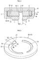
FIG. 1 is a front view illustrating the state where an outer rotor and an inner rotor are disposed in a rotor installation chamber of a gear pump according to a first embodiment of the invention; -
FIG. 2 is a sectional view of the gear pump taken along the line II-II inFIG. 1 ; -
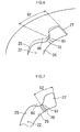
FIG. 3 is a perspective view illustrating a narrowing portion formed at a portion of a radially outer side wall portion of a suction port groove, the portion being close to a terminal end wall portion of the suction port groove; -
FIG. 4 is a front view illustrating the narrowing portion formed at the portion of the radially outer side wall portion of the suction port groove, the portion being close to the terminal end wall portion of the suction port groove; -
FIG. 5 is an explanatory view illustrating the state where oil is pressurized (the pressure of the oil is increased) in a pressurizing region defined by the narrowing portion; -
FIG. 6 is a perspective view illustrating the state where a portion with a smaller groove depth is formed in a suction port groove of a gear pump according to a second embodiment of the invention, the portion being located in a pressurizing region; -
FIG. 7 is a front view illustrating the state where the portion with the smaller groove depth is formed in the pressurizing region; -
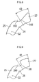
FIG. 8 is an explanatory view of a first modified example achieved by changing the shape of the groove from a maximum narrowing portion of the narrowing portion to the terminal end wall portion of the suction port groove; -
FIG. 9 is an explanatory view of a second modified example achieved by changing the shape of the groove from a maximum narrowing portion of the narrowing portion to the terminal end wall portion of the suction port groove. - Hereinafter, example embodiments of the invention will be described in detail. A gear pump according to a first embodiment of the invention will be described with reference to the accompanying drawings. As illustrated in
FIG. 1 andFIG. 2 , the gear pump includes apump body 10, apump cover 20, anouter rotor 40, aninner rotor 45, and a drive shaft 1. Thepump body 10 has a disc-shaped bottom wall 11, and aperipheral wall 13 formed into a cylindrical shape along a peripheral edge portion of thebottom wall 11. Arecessed portion 14 that opens toward one end of thepump body 10 is defined by thebottom wall 11 and theperipheral wall 13. Thebottom wall 11 has a through-hole 12 of which the center is located at a position offset from the center of thebottom wall 11 by an amount corresponding to an eccentric amount A that is the distance between the center of the outer rotor 40 (describer later) and the center of the inner rotor 45 (described later). Thepump cover 20 is hermetically attached to an end face of theperipheral wall 13 of thepump body 10 with, for example, bolts (not illustrated) to close therecessed portion 14 of thepump body 10. As a result, arotor installation chamber 15 is formed. - As illustrated in
FIG. 1 andFIG. 2 , theouter rotor 40 is rotatably fitted in therotor installation chamber 15. A plurality ofinternal teeth 41 is formed on the inner peripheral face of theouter rotor 40. Theinternal teeth 41 are arranged in the circumferential direction of theouter rotor 40. Theinner rotor 45 is disposed radially inward of the inner peripheral face of theouter rotor 40 such that the center of theinner rotor 45 is offset from the center of theouter rotor 40 by the eccentric amount A. A plurality ofexternal teeth 46 that engage with theinternal teeth 41 of theouter rotor 40 is formed on the outer peripheral face of theinner rotor 45. Theexternal teeth 46 are arranged in the circumferential direction of theinner rotor 45.Gear chambers 50 are defined between theinternal teeth 41 of theouter rotor 40 and theexternal teeth 46 of theinner rotor 45 so as to be expandable and contractable. Anon-circular shaft hole 47 is formed at a center portion of theinner rotor 45. Adistal end portion 2 of the drive shaft 1, which has been passed through the through-hole 12 of thepump body 10, is inserted into theshaft hole 47. In the first embodiment, aflat face 3 is formed by chamfering the outer peripheral face of thedistal end portion 2 of the drive shaft 1 in the axial direction of the drive shaft 1. Further, aflat portion 48 is formed in the inner peripheral face of theinner rotor 45, which defines theshaft hole 47, at such a position as to be opposed to theflat face 3. Theflat portion 48 is formed so as to form the chord of an arc of theshaft hole 47. As theinner rotor 45 rotates upon reception of torque transmitted from the drive shaft 1, theouter rotor 40 is rotated in accordance with the rotation of theinner rotor 45 with theinternal teeth 41 of theouter rotor 40 meshed with theexternal teeth 46 of theinner rotor 45. Thus, the pumping action is carried out. - As illustrated in
FIG. 2 , asuction port groove 22 and adischarge port groove 31 are formed in at least one of thepump body 10 and thepump cover 20. In the first embodiment, thesuction port groove 22 and thedischarge port groove 31 are formed in each of both thepump body 10 and thepump cover 20. Eachsuction port groove 22 forms a suction port, and has an arc shape in a front view of the gear pump. Eachdischarge port groove 31 forms a discharge port, and has an arc shape in the front view of the gear pump. Thesuction port groove 22 is connected to a suction path (not illustrated), and thedischarge port groove 31 is connected to a discharge path (not illustrated). - As illustrated in
FIG. 3 andFIG. 4 , a narrowingportion 60 is formed at a portion of a radially outerside wall portion 25 of thesuction port groove 22, the portion being close to a terminalend wall portion 27 of thesuction port groove 22. The narrowingportion 60 bulges toward a radially innerside wall portion 26 of thesuction port groove 22, thereby narrowing the groove width in the radial direction. In the embodiment, as illustrated inFIG. 3 to FIG. 5 , the narrowingportion 60 bulges in a semi-arc chevron shape. A pressurizingregion 62 is formed between amaximum narrowing portion 61, which is an apex of the narrowingportion 60, and the terminalend wall portion 27. The pressurizingregion 62 is used to pressurize the oil in thegear chamber 50 that is defined between theinternal tooth 41 and theexternal tooth 46 located at a position on thesuction port groove 22 side and closest to the terminalend wall portion 27. - The bulging position of the narrowing
portion 60 with respect to the radially outerside wall portion 25 of thesuction port groove 22 is set such that the pressurizingregion 62 is formed in a range from the terminalend wall portion 27 of thesuction port groove 22 to a position that is apart from the terminalend wall portion 27 by a distance corresponding to one pitch of theinternal teeth 41. Thesuction port groove 22 is formed such that the groove width in the radial direction gradually increases from themaximum narrowing portion 61 of the narrowingportion 60 toward the terminalend wall portion 27. - The gear pump according to the first embodiment is configured as described above. Thus, while the gear pump is operating, the
inner rotor 45 is driven to be rotated clockwise in a direction indicated by an arrow P inFIG. 1 upon reception of torque transmitted from the drive shaft 1, and theouter rotor 40 is rotated in accordance with the rotation of theinner rotor 45. As thegear chambers 50 defined between theinternal teeth 41 of theouter rotor 40 and theexternal teeth 46 of theinner rotor 45 are expanded and contracted, the oil supplied to thesuction port groove 22 is sucked into thegear chambers 50 defined between theinternal teeth 41 of theouter rotor 40 and theexternal teeth 46 of theinner rotor 45 and then discharged from thegear chambers 50 into thedischarge port groove 31. - The flows of oil near the terminal
end wall portion 27 of thesuction port groove 22 during the pump operation are indicated by arrows inFIG. 5 . That is, after the low-pressure oil located on thesuction port groove 22 side is sucked into thegear chamber 50, the sucked oil flows radially outward under the action of centrifugal force and is pressurized (the pressure of the oil is increased). Part of the pressurized oil flows toward the terminalend wall portion 27 along the narrowingportion 60 of thesuction port groove 22, flows along the terminalend wall portion 27, and flows toward the narrowingportion 60. Thus, the pressure of the oil is increased to a high pressure and the high-pressure state is maintained in the pressurizingregion 62 defined by the narrowingportion 60 that bulges from a portion of the radially outerside wall portion 25, which is close to the terminalend wall portion 27 of thesuction port groove 22. - As described above, it is possible to increase the pressure of the oil in the
gear chamber 50 defined between theinternal tooth 41 and theexternal tooth 46 located at a position on thesuction port groove 22 side and closest to the terminalend wall portion 27 of thesuction port groove 22. Thus, it is possible to appropriately suppress occurrence of cavitation in the oil in thegear chambers 50. As a result, it is possible to suppress, for example, a decrease in the oil discharge amount, hydraulic vibrations, and abnormal noise, which are caused by the cavitation. - In the first embodiment, the bulging position of the
maximum narrowing portion 61 of the narrowingportion 60 with respect to the radially outerside wall portion 25 of thesuction port groove 22 is set such that the pressurizingregion 62 is formed in the range from the terminalend wall portion 27 of thesuction port groove 22 to the position that is apart from the terminalend wall portion 27 by the distance corresponding to one pitch of the internal teeth 41 (the distance may be slightly smaller or larger than one pitch). Thus, it is possible to efficiently pressurize the oil (increase the pressure of the oil) in thegear chamber 50 defined between theinternal tooth 41 and theexternal tooth 46 located at a position on thesuction port groove 22 side and closest to the terminalend wall portion 27 of thesuction port groove 22. - In the first embodiment, as illustrated in
FIG. 3 andFIG. 4 , thesuction port groove 22 is formed such that the groove width in the radial direction gradually increases from themaximum narrowing portion 61 of the narrowingportion 60 toward the terminalend wall portion 27. Thus, the oil is smoothly suctioned in thegear chamber 50 defined between theinternal tooth 41 and theexternal tooth 46 located at a position on thesuction port groove 22 side and closest to the terminalend wall portion 27 of thesuction port groove 22. As a result, it is possible to suppress occurrence of insufficient suction of oil. - Next, a second embodiment of the invention will be described with reference to
FIG. 6 and FIG. 7 . As illustrated inFIG. 6 and FIG. 7 , in the second embodiment, a portion having a smaller groove depth is formed in the pressurizingregion 62 defined by the narrowingportion 60 that bulges from the radially outerside wall portion 25 of thesuction port groove 22. In the second embodiment, aprojection 70, which has an arc sectional shape, projects from the groove bottom face, and extends in the radial direction, is formed at a position at themaximum narrowing portion 61 of the narrowingportion 60 of thesuction port groove 22. Because the other configurations in the second embodiment are the same as those in the first embodiment, the same configurations as those in the first embodiment will be denoted by the same reference symbols as those in the first embodiment, and description thereof will be omitted. - In the second embodiment, the same operation and advantageous effects as those in the first embodiment are obtained. In particular, the
projection 70 that forms a smaller groove-depth portion restrains the oil pressurized in the pressurizingregion 62 from flowing into a portion of thesuction port groove 22, the portion being located outside the pressurizingregion 62. Thus, it is possible to efficiently pressurize the oil (increase the pressure of the oil) in thegear chamber 50 defined between theinternal tooth 41 and theexternal tooth 46 located at a position on thesuction port groove 22 side and closest to the terminalend wall portion 27 of thesuction port groove 22. Thus, it is possible to further appropriately suppress occurrence of cavitation. - The invention is not limited to the first and second embodiments, and may be implemented in various other embodiments within the scope of the invention. For example, in the first and second embodiments, the narrowing
portion 60 bulges toward the radially innerside wall portion 26 of thesuction port groove 22 from a portion of the radially outerside wall portion 25, the portion being close to the terminalend wall portion 27 of thesuction port groove 22, thereby narrowing the groove width in the radial direction, and the narrowingportion 60 bulges in a semi-arc chevron shape. However, as illustrated inFIG. 8 , asloped narrowing portion 160 may be formed such that the groove width is gradually increased toward the radially outerside wall portion 25 from amaximum narrowing portion 161 of the narrowingportion 160 of thesuction port groove 22. As illustrated inFIG. 9 , a narrowingportion 260 may be formed into such a shape that the groove width is abruptly increased toward the radially outerside wall portion 25 from amaximum narrowing portion 261 of the narrowingportion 260 of thesuction port groove 22. In the first and second embodiments, thesuction port groove 22 that forms the suction port and thedischarge port groove 31 that forms the discharge port are formed in each of both thepump body 10 and thepump cover 20. However, the invention may be implemented in the case where thesuction port groove 22 and thedischarge port groove 31 are formed in one of thepump body 10 and thepump cover 20. - In a gear pump, an outer rotor (40) and an inner rotor (45) are disposed in a rotor installation chamber (15) defined by a pump body (10) and a pump cover (20). A suction port groove (22) and a discharge port groove (31) are formed in at least one of the pump body (10) and the pump cover (20). A narrowing portion (60) is formed at a portion of a radially outer side wall portion (25) of the suction port groove (22), the portion being close to a terminal end wall portion (27) of the suction port groove (22). The narrowing portion (60) narrows the groove width in the radial direction. A pressurizing region (62) that pressurizes oil in the gear chamber (50) is formed between the narrowing portion (60) and the terminal end wall portion (27).
Claims (5)
- A gear pump comprising:a pump body;a pump cover;an outer rotor having a plurality of internal teeth; andan inner rotor having external teeth meshed with the internal teeth and driven to be rotated, whereina rotor installation chamber is defined by the pump body and the pump cover,the outer rotor and the inner rotor are disposed in the rotor installation chamber, and gear chambers are defined between the internal teeth of the outer rotor and the external teeth of the inner rotor,a suction port groove that forms a suction port and a discharge port groove that forms a discharge port are formed in at least one of the pump body and the pump cover,a narrowing portion is formed at a portion of a radially outer side wall portion of the suction port groove, the portion being close to a terminal end wall portion of the suction port groove, the narrowing portion bulging toward a radially inner side wall portion of the suction port groove to narrow a groove width in a radial direction, anda pressurizing region is formed between the narrowing portion and the terminal end wall portion, the pressurizing region pressurizing oil in the gear chamber that is defined between the internal tooth and the external tooth located at a position on the suction port groove side and closest to the terminal end wall portion.
- The gear pump according to claim 1, wherein a bulging position of the narrowing portion with respect to the radially outer side wall portion of the suction port groove is set such that the pressurizing region is formed in a range from the terminal end wall portion of the suction port groove to a position that is apart from the terminal end wall portion by a distance corresponding to one pitch of the internal teeth.
- The gear pump according to claim 1, wherein the suction port groove has a portion with a groove depth smaller than that of the other portion of the suction port, the portion being located in the pressurizing region.
- The gear pump according to claim 2, wherein the suction port groove has a portion with a groove depth smaller than that of the other portion of the suction port, the portion being located in the pressurizing region.
- The gear pump according to any one of claims 1 to 4, wherein the suction port groove is formed such that the groove width in the radial direction gradually increases from the narrowing portion toward the terminal end wall portion.
Applications Claiming Priority (1)
| Application Number | Priority Date | Filing Date | Title |
|---|---|---|---|
| JP2013153699A JP6236958B2 (en) | 2013-07-24 | 2013-07-24 | Gear pump |
Publications (2)
| Publication Number | Publication Date |
|---|---|
| EP2829731A1 true EP2829731A1 (en) | 2015-01-28 |
| EP2829731B1 EP2829731B1 (en) | 2016-09-14 |
Family
ID=51220427
Family Applications (1)
| Application Number | Title | Priority Date | Filing Date |
|---|---|---|---|
| EP14177941.3A Not-in-force EP2829731B1 (en) | 2013-07-24 | 2014-07-22 | Gear pump |
Country Status (4)
| Country | Link |
|---|---|
| US (1) | US9506466B2 (en) |
| EP (1) | EP2829731B1 (en) |
| JP (1) | JP6236958B2 (en) |
| CN (1) | CN104343678B (en) |
Families Citing this family (4)
| Publication number | Priority date | Publication date | Assignee | Title |
|---|---|---|---|---|
| JP3486748B2 (en) | 1999-12-06 | 2004-01-13 | 株式会社三井三池製作所 | Skip guide device |
| JP6152745B2 (en) * | 2013-08-21 | 2017-06-28 | 株式会社ジェイテクト | Gear pump |
| JP6369194B2 (en) * | 2014-07-23 | 2018-08-08 | 株式会社ジェイテクト | Electric pump unit |
| DE102019130723A1 (en) * | 2019-11-14 | 2021-05-20 | Fte Automotive Gmbh | Liquid pump |
Citations (4)
| Publication number | Priority date | Publication date | Assignee | Title |
|---|---|---|---|---|
| US3995978A (en) * | 1975-04-04 | 1976-12-07 | Eaton Corporation | Hydraulic fluid pressure device and porting arrangement therefor |
| JP2005076542A (en) | 2003-09-01 | 2005-03-24 | Aisin Aw Co Ltd | Gear pump and oil pump for automatic transmission using the same |
| WO2006136014A1 (en) * | 2005-06-22 | 2006-12-28 | Stt Technologies Inc., A Joint Venture Of Magna Powertrain Inc. And Shw Gmbh | Gear pump with improved inlet port |
| JP2010096011A (en) * | 2008-10-14 | 2010-04-30 | Sumitomo Electric Sintered Alloy Ltd | Internal gear pump |
Family Cites Families (8)
| Publication number | Priority date | Publication date | Assignee | Title |
|---|---|---|---|---|
| US4836760A (en) * | 1987-03-12 | 1989-06-06 | Parker Hannifin Corporation | Inlet for a positive displacement pump |
| JPH01273887A (en) * | 1988-04-25 | 1989-11-01 | Honda Motor Co Ltd | internal gear type pump |
| JP3530664B2 (en) * | 1996-01-25 | 2004-05-24 | 富士重工業株式会社 | Internal gear type fluid device |
| US6481991B2 (en) * | 2000-03-27 | 2002-11-19 | Denso Corporation | Trochoid gear type fuel pump |
| WO2003048580A1 (en) * | 2001-12-03 | 2003-06-12 | Aisin Aw Co., Ltd. | Gear pump |
| JP4160963B2 (en) * | 2005-03-23 | 2008-10-08 | 株式会社山田製作所 | Oil pump |
| JP5266583B2 (en) * | 2009-01-27 | 2013-08-21 | 住友電工焼結合金株式会社 | Internal gear pump |
| JP5681571B2 (en) * | 2011-06-06 | 2015-03-11 | 株式会社山田製作所 | Oil pump |
-
2013
- 2013-07-24 JP JP2013153699A patent/JP6236958B2/en not_active Expired - Fee Related
-
2014
- 2014-07-22 CN CN201410350630.1A patent/CN104343678B/en not_active Expired - Fee Related
- 2014-07-22 EP EP14177941.3A patent/EP2829731B1/en not_active Not-in-force
- 2014-07-24 US US14/339,603 patent/US9506466B2/en not_active Expired - Fee Related
Patent Citations (4)
| Publication number | Priority date | Publication date | Assignee | Title |
|---|---|---|---|---|
| US3995978A (en) * | 1975-04-04 | 1976-12-07 | Eaton Corporation | Hydraulic fluid pressure device and porting arrangement therefor |
| JP2005076542A (en) | 2003-09-01 | 2005-03-24 | Aisin Aw Co Ltd | Gear pump and oil pump for automatic transmission using the same |
| WO2006136014A1 (en) * | 2005-06-22 | 2006-12-28 | Stt Technologies Inc., A Joint Venture Of Magna Powertrain Inc. And Shw Gmbh | Gear pump with improved inlet port |
| JP2010096011A (en) * | 2008-10-14 | 2010-04-30 | Sumitomo Electric Sintered Alloy Ltd | Internal gear pump |
Also Published As
| Publication number | Publication date |
|---|---|
| US20150030488A1 (en) | 2015-01-29 |
| JP6236958B2 (en) | 2017-11-29 |
| JP2015025375A (en) | 2015-02-05 |
| CN104343678B (en) | 2018-07-06 |
| CN104343678A (en) | 2015-02-11 |
| EP2829731B1 (en) | 2016-09-14 |
| US9506466B2 (en) | 2016-11-29 |
Similar Documents
| Publication | Publication Date | Title |
|---|---|---|
| US8801411B2 (en) | Internal-gear type fluid device | |
| JP6329775B2 (en) | Vane pump | |
| US9581156B2 (en) | Gear pump including an inner rotor having a plurality of teeth | |
| EP2829731B1 (en) | Gear pump | |
| DE102015002352A1 (en) | Electric oil pump, in particular for a motor vehicle | |
| RU2492358C2 (en) | Impeller and vane pump | |
| CN107035682B (en) | Oil pump | |
| WO2011135746A1 (en) | Vane pump | |
| US9273688B2 (en) | Pump rotor and internal gear pump using the same | |
| EP2746583A1 (en) | Vane pump | |
| US12044238B2 (en) | Gear pump or motor with communication paths to suction and discharge in closed space between the drive and driven gears | |
| EP2789854A1 (en) | Fluid-pressure apparatus | |
| JP6152745B2 (en) | Gear pump | |
| CN112673176B (en) | Vane Pump Unit | |
| JP6784543B2 (en) | Vane pump | |
| JP6031311B2 (en) | Variable displacement vane pump | |
| JP4485770B2 (en) | Oil pump rotor | |
| KR101583935B1 (en) | Oil pump having two rotors for reducing pulsation of automatic transmission | |
| US9765773B2 (en) | Pump having an inner and outer rotor | |
| JPWO2020026338A1 (en) | Vane pump device, design method of vane pump device | |
| JP6503855B2 (en) | Trochoid pump | |
| JP2018105199A (en) | Oil pump | |
| WO2025115570A1 (en) | Vane pump | |
| US20200408117A1 (en) | Gerotor-type oil pump | |
| JP2014055526A (en) | Oil pump |
Legal Events
| Date | Code | Title | Description |
|---|---|---|---|
| 17P | Request for examination filed |
Effective date: 20140722 |
|
| AK | Designated contracting states |
Kind code of ref document: A1 Designated state(s): AL AT BE BG CH CY CZ DE DK EE ES FI FR GB GR HR HU IE IS IT LI LT LU LV MC MK MT NL NO PL PT RO RS SE SI SK SM TR |
|
| AX | Request for extension of the european patent |
Extension state: BA ME |
|
| PUAI | Public reference made under article 153(3) epc to a published international application that has entered the european phase |
Free format text: ORIGINAL CODE: 0009012 |
|
| R17P | Request for examination filed (corrected) |
Effective date: 20150202 |
|
| RIC1 | Information provided on ipc code assigned before grant |
Ipc: F04C 2/10 20060101AFI20160205BHEP Ipc: F04C 15/00 20060101ALI20160205BHEP Ipc: F04C 2/08 20060101ALI20160205BHEP |
|
| GRAP | Despatch of communication of intention to grant a patent |
Free format text: ORIGINAL CODE: EPIDOSNIGR1 |
|
| INTG | Intention to grant announced |
Effective date: 20160322 |
|
| GRAS | Grant fee paid |
Free format text: ORIGINAL CODE: EPIDOSNIGR3 |
|
| GRAA | (expected) grant |
Free format text: ORIGINAL CODE: 0009210 |
|
| AK | Designated contracting states |
Kind code of ref document: B1 Designated state(s): AL AT BE BG CH CY CZ DE DK EE ES FI FR GB GR HR HU IE IS IT LI LT LU LV MC MK MT NL NO PL PT RO RS SE SI SK SM TR |
|
| REG | Reference to a national code |
Ref country code: GB Ref legal event code: FG4D |
|
| REG | Reference to a national code |
Ref country code: CH Ref legal event code: EP |
|
| REG | Reference to a national code |
Ref country code: IE Ref legal event code: FG4D |
|
| REG | Reference to a national code |
Ref country code: AT Ref legal event code: REF Ref document number: 829315 Country of ref document: AT Kind code of ref document: T Effective date: 20161015 |
|
| REG | Reference to a national code |
Ref country code: DE Ref legal event code: R096 Ref document number: 602014003625 Country of ref document: DE |
|
| REG | Reference to a national code |
Ref country code: LT Ref legal event code: MG4D |
|
| REG | Reference to a national code |
Ref country code: NL Ref legal event code: MP Effective date: 20160914 |
|
| PG25 | Lapsed in a contracting state [announced via postgrant information from national office to epo] |
Ref country code: LT Free format text: LAPSE BECAUSE OF FAILURE TO SUBMIT A TRANSLATION OF THE DESCRIPTION OR TO PAY THE FEE WITHIN THE PRESCRIBED TIME-LIMIT Effective date: 20160914 Ref country code: NO Free format text: LAPSE BECAUSE OF FAILURE TO SUBMIT A TRANSLATION OF THE DESCRIPTION OR TO PAY THE FEE WITHIN THE PRESCRIBED TIME-LIMIT Effective date: 20161214 Ref country code: FI Free format text: LAPSE BECAUSE OF FAILURE TO SUBMIT A TRANSLATION OF THE DESCRIPTION OR TO PAY THE FEE WITHIN THE PRESCRIBED TIME-LIMIT Effective date: 20160914 Ref country code: HR Free format text: LAPSE BECAUSE OF FAILURE TO SUBMIT A TRANSLATION OF THE DESCRIPTION OR TO PAY THE FEE WITHIN THE PRESCRIBED TIME-LIMIT Effective date: 20160914 Ref country code: RS Free format text: LAPSE BECAUSE OF FAILURE TO SUBMIT A TRANSLATION OF THE DESCRIPTION OR TO PAY THE FEE WITHIN THE PRESCRIBED TIME-LIMIT Effective date: 20160914 |
|
| REG | Reference to a national code |
Ref country code: AT Ref legal event code: MK05 Ref document number: 829315 Country of ref document: AT Kind code of ref document: T Effective date: 20160914 |
|
| PG25 | Lapsed in a contracting state [announced via postgrant information from national office to epo] |
Ref country code: SE Free format text: LAPSE BECAUSE OF FAILURE TO SUBMIT A TRANSLATION OF THE DESCRIPTION OR TO PAY THE FEE WITHIN THE PRESCRIBED TIME-LIMIT Effective date: 20160914 Ref country code: LV Free format text: LAPSE BECAUSE OF FAILURE TO SUBMIT A TRANSLATION OF THE DESCRIPTION OR TO PAY THE FEE WITHIN THE PRESCRIBED TIME-LIMIT Effective date: 20160914 Ref country code: GR Free format text: LAPSE BECAUSE OF FAILURE TO SUBMIT A TRANSLATION OF THE DESCRIPTION OR TO PAY THE FEE WITHIN THE PRESCRIBED TIME-LIMIT Effective date: 20161215 Ref country code: NL Free format text: LAPSE BECAUSE OF FAILURE TO SUBMIT A TRANSLATION OF THE DESCRIPTION OR TO PAY THE FEE WITHIN THE PRESCRIBED TIME-LIMIT Effective date: 20160914 |
|
| PG25 | Lapsed in a contracting state [announced via postgrant information from national office to epo] |
Ref country code: EE Free format text: LAPSE BECAUSE OF FAILURE TO SUBMIT A TRANSLATION OF THE DESCRIPTION OR TO PAY THE FEE WITHIN THE PRESCRIBED TIME-LIMIT Effective date: 20160914 Ref country code: RO Free format text: LAPSE BECAUSE OF FAILURE TO SUBMIT A TRANSLATION OF THE DESCRIPTION OR TO PAY THE FEE WITHIN THE PRESCRIBED TIME-LIMIT Effective date: 20160914 |
|
| PG25 | Lapsed in a contracting state [announced via postgrant information from national office to epo] |
Ref country code: IS Free format text: LAPSE BECAUSE OF FAILURE TO SUBMIT A TRANSLATION OF THE DESCRIPTION OR TO PAY THE FEE WITHIN THE PRESCRIBED TIME-LIMIT Effective date: 20170114 Ref country code: ES Free format text: LAPSE BECAUSE OF FAILURE TO SUBMIT A TRANSLATION OF THE DESCRIPTION OR TO PAY THE FEE WITHIN THE PRESCRIBED TIME-LIMIT Effective date: 20160914 Ref country code: PT Free format text: LAPSE BECAUSE OF FAILURE TO SUBMIT A TRANSLATION OF THE DESCRIPTION OR TO PAY THE FEE WITHIN THE PRESCRIBED TIME-LIMIT Effective date: 20170116 Ref country code: PL Free format text: LAPSE BECAUSE OF FAILURE TO SUBMIT A TRANSLATION OF THE DESCRIPTION OR TO PAY THE FEE WITHIN THE PRESCRIBED TIME-LIMIT Effective date: 20160914 Ref country code: BG Free format text: LAPSE BECAUSE OF FAILURE TO SUBMIT A TRANSLATION OF THE DESCRIPTION OR TO PAY THE FEE WITHIN THE PRESCRIBED TIME-LIMIT Effective date: 20161214 Ref country code: SK Free format text: LAPSE BECAUSE OF FAILURE TO SUBMIT A TRANSLATION OF THE DESCRIPTION OR TO PAY THE FEE WITHIN THE PRESCRIBED TIME-LIMIT Effective date: 20160914 Ref country code: BE Free format text: LAPSE BECAUSE OF FAILURE TO SUBMIT A TRANSLATION OF THE DESCRIPTION OR TO PAY THE FEE WITHIN THE PRESCRIBED TIME-LIMIT Effective date: 20160914 Ref country code: AT Free format text: LAPSE BECAUSE OF FAILURE TO SUBMIT A TRANSLATION OF THE DESCRIPTION OR TO PAY THE FEE WITHIN THE PRESCRIBED TIME-LIMIT Effective date: 20160914 Ref country code: CZ Free format text: LAPSE BECAUSE OF FAILURE TO SUBMIT A TRANSLATION OF THE DESCRIPTION OR TO PAY THE FEE WITHIN THE PRESCRIBED TIME-LIMIT Effective date: 20160914 Ref country code: SM Free format text: LAPSE BECAUSE OF FAILURE TO SUBMIT A TRANSLATION OF THE DESCRIPTION OR TO PAY THE FEE WITHIN THE PRESCRIBED TIME-LIMIT Effective date: 20160914 |
|
| REG | Reference to a national code |
Ref country code: FR Ref legal event code: PLFP Year of fee payment: 4 |
|
| REG | Reference to a national code |
Ref country code: DE Ref legal event code: R097 Ref document number: 602014003625 Country of ref document: DE |
|
| PG25 | Lapsed in a contracting state [announced via postgrant information from national office to epo] |
Ref country code: IT Free format text: LAPSE BECAUSE OF FAILURE TO SUBMIT A TRANSLATION OF THE DESCRIPTION OR TO PAY THE FEE WITHIN THE PRESCRIBED TIME-LIMIT Effective date: 20160914 |
|
| PLBE | No opposition filed within time limit |
Free format text: ORIGINAL CODE: 0009261 |
|
| STAA | Information on the status of an ep patent application or granted ep patent |
Free format text: STATUS: NO OPPOSITION FILED WITHIN TIME LIMIT |
|
| PG25 | Lapsed in a contracting state [announced via postgrant information from national office to epo] |
Ref country code: DK Free format text: LAPSE BECAUSE OF FAILURE TO SUBMIT A TRANSLATION OF THE DESCRIPTION OR TO PAY THE FEE WITHIN THE PRESCRIBED TIME-LIMIT Effective date: 20160914 |
|
| 26N | No opposition filed |
Effective date: 20170615 |
|
| PG25 | Lapsed in a contracting state [announced via postgrant information from national office to epo] |
Ref country code: SI Free format text: LAPSE BECAUSE OF FAILURE TO SUBMIT A TRANSLATION OF THE DESCRIPTION OR TO PAY THE FEE WITHIN THE PRESCRIBED TIME-LIMIT Effective date: 20160914 |
|
| REG | Reference to a national code |
Ref country code: CH Ref legal event code: PL |
|
| REG | Reference to a national code |
Ref country code: IE Ref legal event code: MM4A |
|
| PG25 | Lapsed in a contracting state [announced via postgrant information from national office to epo] |
Ref country code: IE Free format text: LAPSE BECAUSE OF NON-PAYMENT OF DUE FEES Effective date: 20170722 Ref country code: LI Free format text: LAPSE BECAUSE OF NON-PAYMENT OF DUE FEES Effective date: 20170731 Ref country code: CH Free format text: LAPSE BECAUSE OF NON-PAYMENT OF DUE FEES Effective date: 20170731 |
|
| REG | Reference to a national code |
Ref country code: FR Ref legal event code: PLFP Year of fee payment: 5 |
|
| PG25 | Lapsed in a contracting state [announced via postgrant information from national office to epo] |
Ref country code: LU Free format text: LAPSE BECAUSE OF NON-PAYMENT OF DUE FEES Effective date: 20170722 |
|
| PG25 | Lapsed in a contracting state [announced via postgrant information from national office to epo] |
Ref country code: MT Free format text: LAPSE BECAUSE OF NON-PAYMENT OF DUE FEES Effective date: 20170722 |
|
| PG25 | Lapsed in a contracting state [announced via postgrant information from national office to epo] |
Ref country code: AL Free format text: LAPSE BECAUSE OF FAILURE TO SUBMIT A TRANSLATION OF THE DESCRIPTION OR TO PAY THE FEE WITHIN THE PRESCRIBED TIME-LIMIT Effective date: 20160914 |
|
| GBPC | Gb: european patent ceased through non-payment of renewal fee |
Effective date: 20180722 |
|
| PG25 | Lapsed in a contracting state [announced via postgrant information from national office to epo] |
Ref country code: GB Free format text: LAPSE BECAUSE OF NON-PAYMENT OF DUE FEES Effective date: 20180722 |
|
| PG25 | Lapsed in a contracting state [announced via postgrant information from national office to epo] |
Ref country code: HU Free format text: LAPSE BECAUSE OF FAILURE TO SUBMIT A TRANSLATION OF THE DESCRIPTION OR TO PAY THE FEE WITHIN THE PRESCRIBED TIME-LIMIT; INVALID AB INITIO Effective date: 20140722 Ref country code: MC Free format text: LAPSE BECAUSE OF FAILURE TO SUBMIT A TRANSLATION OF THE DESCRIPTION OR TO PAY THE FEE WITHIN THE PRESCRIBED TIME-LIMIT Effective date: 20160914 |
|
| PGFP | Annual fee paid to national office [announced via postgrant information from national office to epo] |
Ref country code: FR Payment date: 20190619 Year of fee payment: 6 |
|
| PG25 | Lapsed in a contracting state [announced via postgrant information from national office to epo] |
Ref country code: CY Free format text: LAPSE BECAUSE OF FAILURE TO SUBMIT A TRANSLATION OF THE DESCRIPTION OR TO PAY THE FEE WITHIN THE PRESCRIBED TIME-LIMIT Effective date: 20160914 |
|
| PGFP | Annual fee paid to national office [announced via postgrant information from national office to epo] |
Ref country code: DE Payment date: 20190710 Year of fee payment: 6 |
|
| PG25 | Lapsed in a contracting state [announced via postgrant information from national office to epo] |
Ref country code: MK Free format text: LAPSE BECAUSE OF FAILURE TO SUBMIT A TRANSLATION OF THE DESCRIPTION OR TO PAY THE FEE WITHIN THE PRESCRIBED TIME-LIMIT Effective date: 20160914 |
|
| PG25 | Lapsed in a contracting state [announced via postgrant information from national office to epo] |
Ref country code: TR Free format text: LAPSE BECAUSE OF FAILURE TO SUBMIT A TRANSLATION OF THE DESCRIPTION OR TO PAY THE FEE WITHIN THE PRESCRIBED TIME-LIMIT Effective date: 20160914 |
|
| REG | Reference to a national code |
Ref country code: DE Ref legal event code: R119 Ref document number: 602014003625 Country of ref document: DE |
|
| PG25 | Lapsed in a contracting state [announced via postgrant information from national office to epo] |
Ref country code: FR Free format text: LAPSE BECAUSE OF NON-PAYMENT OF DUE FEES Effective date: 20200731 |
|
| PG25 | Lapsed in a contracting state [announced via postgrant information from national office to epo] |
Ref country code: DE Free format text: LAPSE BECAUSE OF NON-PAYMENT OF DUE FEES Effective date: 20210202 |