EP2829673A1 - An adapter for a lock case - Google Patents
An adapter for a lock case Download PDFInfo
- Publication number
- EP2829673A1 EP2829673A1 EP13177440.8A EP13177440A EP2829673A1 EP 2829673 A1 EP2829673 A1 EP 2829673A1 EP 13177440 A EP13177440 A EP 13177440A EP 2829673 A1 EP2829673 A1 EP 2829673A1
- Authority
- EP
- European Patent Office
- Prior art keywords
- lock
- handle
- door
- bushing
- adapter
- Prior art date
- Legal status (The legal status is an assumption and is not a legal conclusion. Google has not performed a legal analysis and makes no representation as to the accuracy of the status listed.)
- Withdrawn
Links
- 230000005540 biological transmission Effects 0.000 claims abstract description 10
- 230000000284 resting effect Effects 0.000 description 4
- 238000009434 installation Methods 0.000 description 3
- 230000001419 dependent effect Effects 0.000 description 2
- 238000012423 maintenance Methods 0.000 description 2
- 239000002184 metal Substances 0.000 description 2
- 229910052751 metal Inorganic materials 0.000 description 2
- HCHKCACWOHOZIP-UHFFFAOYSA-N Zinc Chemical compound [Zn] HCHKCACWOHOZIP-UHFFFAOYSA-N 0.000 description 1
- 239000000463 material Substances 0.000 description 1
- 238000000034 method Methods 0.000 description 1
- 238000003801 milling Methods 0.000 description 1
- 238000000465 moulding Methods 0.000 description 1
- 239000007787 solid Substances 0.000 description 1
- 238000003466 welding Methods 0.000 description 1
- 229910052725 zinc Inorganic materials 0.000 description 1
- 239000011701 zinc Substances 0.000 description 1
Images
Classifications
-
- E—FIXED CONSTRUCTIONS
- E05—LOCKS; KEYS; WINDOW OR DOOR FITTINGS; SAFES
- E05B—LOCKS; ACCESSORIES THEREFOR; HANDCUFFS
- E05B65/00—Locks or fastenings for special use
- E05B65/10—Locks or fastenings for special use for panic or emergency doors
- E05B65/1086—Locks with panic function, e.g. allowing opening from the inside without a ley even when locked from the outside
-
- E—FIXED CONSTRUCTIONS
- E05—LOCKS; KEYS; WINDOW OR DOOR FITTINGS; SAFES
- E05B—LOCKS; ACCESSORIES THEREFOR; HANDCUFFS
- E05B59/00—Locks with latches separate from the lock-bolts or with a plurality of latches or lock-bolts
-
- E—FIXED CONSTRUCTIONS
- E05—LOCKS; KEYS; WINDOW OR DOOR FITTINGS; SAFES
- E05B—LOCKS; ACCESSORIES THEREFOR; HANDCUFFS
- E05B47/00—Operating or controlling locks or other fastening devices by electric or magnetic means
- E05B2047/0048—Circuits, feeding, monitoring
- E05B2047/0067—Monitoring
- E05B2047/0069—Monitoring bolt position
-
- E—FIXED CONSTRUCTIONS
- E05—LOCKS; KEYS; WINDOW OR DOOR FITTINGS; SAFES
- E05B—LOCKS; ACCESSORIES THEREFOR; HANDCUFFS
- E05B41/00—Locks with visible indication as to whether the lock is locked or unlocked
-
- E—FIXED CONSTRUCTIONS
- E05—LOCKS; KEYS; WINDOW OR DOOR FITTINGS; SAFES
- E05B—LOCKS; ACCESSORIES THEREFOR; HANDCUFFS
- E05B63/00—Locks or fastenings with special structural characteristics
- E05B63/0065—Operating modes; Transformable to different operating modes
Definitions
- the present invention relates to an adapter for a lock case for opening a locked door without a key or a locking knob.
- the present invention relates to an adapter to be connected to a lock case for always allowing a person to open a door from the inside without a key, a knob or a handle, even if said door is locked.
- split spindle system which is arranged to disengage the inner handle from the outer handle in such way the door may be opened from the inside even though it is locked from the outside.
- split spindle solution may be utilized such that the inner door handle always is connected to the lock bolt, whereby the outer door handle is disconnected from the lock bolt.
- One disadvantage is that the installation of the split spindle system usually is made in extremely small or narrow areas or surfaces inside the lock case, which areas and/or surfaces may get worn out if the door is constantly used; doors in schools are one example. When the split spindle gets worn out the entire system may stop working and the door may not be opened. Such damage will result in the inner door handle to always be disengaged from the lock bolt which means that if the door is locked, a person entrapped inside the door will have no possibility to exit.
- split-spindle system operates on small and narrow surfaces it may be complicated to install the system, for new installations as well as when it needs to be replaced or maintained.
- An object of the present invention is to provide a new adapter for a lock case, which is improved over prior art. This object is achieved be a technique defined in the appended independent claims; certain embodiment being set forth in the related dependent claims.
- an adapter for a lock case comprising a handle bushing to be connected to a handle and arranged to be rotated about a first axis when the handle is pushed down or pulled up for moving a latch bolt in and out from said lock case.
- the adapter comprises a lock bushing to be connected to a lock follower extending through said lock case and arranged to rotate about a second axis for moving a lock bolt in and out from said lock case, and a transmission connecting said handle bushing with said lock bushing such that the lock bushing is arranged to rotate in a first direction when the handle bushing is rotated in a second direction being opposite said first direction.
- the adapter is adapted to be arranged on one side of a door, between a door leaf and the door handle. This is advantageous when the adapter is used on a door which is used as e.g. an emergency door or a hotel door where it is necessary and desired to be able to open the locked door and get out.
- the adapter is adapted to be detachable from said door which is advantageous since it is possible to then post-install the adapter to a door which is already installed.
- the transmission comprises a handle lever connected to the handle bushing, and a lock lever which is connected to the lock bushing and which is in constant contact with the handle lever such that the lock lever always rotates with the handle lever. Since the lock bushing always is in contact with the handle lever the adapter never has to be switch on which to function.
- the handle lever is biased such that it automatically returns to an idle state, corresponding to a horizontally aligned position of the door handle, when a force for pushing down the door handle has been released. This is as above also an assurance that the door is always locked except for when the handle is pushed down, which is advantageous for e.g. emergency doors.
- the adapter further comprises a casing including a cover portion and a support portion which are connected by fastening means, wherein the cover portion protects the other components of the adapter from externals.
- the support portion comprises a track in which the lock lever is guided when it rotates about the second axis.
- the guidance of the track is advantageous since it provides a safe and predetermined transmission of the lock lever.
- the adapter further comprises an indicator configured to indicate an active and/or inactive state of said adapter, which is advantageous since it provides a clear indication whether the adapter is able to accomplish its function.
- a door lock assembly for mounting to a door leaf, comprising a lock case including a latch bolt to be operated by at least one door handle connected to a door handle follower of said lock case, a lock bolt in connection with a lock follower of said lock case, and an adapter as described above, connected to said lock case.
- a door comprising a door lock assembly mentioned above.
- an adapter 10 including a casing 20 and a transmission 50 which is suitable to use together with a lock case of a door.
- the casing 20 comprises a cover portion 21 which comprises a base member 22 and a side member 23 surrounding the base member 22 along its periphery and extending perpendicularly from said base member 22.
- the base member 22 and the side member 23 are in this case integrally formed and made in one piece, casted in preferably zinc.
- the base member 22 may be mounted, e.g. by welding, to one edge of the side member 23 such that they together may accommodate a support portion 24.
- the base member 22 and the side member 23 may made in one piece.
- the cover portion 21 further includes a first circular opening 25a which is centered arranged about a fist axis A, and a second circular opening 26a which is centered arranged about a second axis B.
- the first opening 25a of the cover portion 21 corresponds to a first opening 25b of the support portion 24 which is also centered arranged about the first axis A.
- the second opening 26a of the cover portion 21 corresponds to a second opening 26b of the support portion 24 and centered arranged about the second axis B.
- the support portion 24 is preferably made in a solid piece which has the same outer shape and size as the base member 22 of the cover portion 21.
- the base member 22 and the side member 23 of the cover portion 21 enclose the support portion 24 with the exception of the rear outer surface of the support portion 24, adapted to be in close contact with the door.
- the cover portion 21 and the support portion 24 are assembled by means of fastening means, in this case screws 27a-d which are inserted into threaded holes 28a-h in the cover portion 21 and the support portion 24.
- the two portions 21, 24 are preferably made of a castable material such as metal or plastic.
- the support portion 24 further comprises a spring recess 29 for receiving a spring 40 and at least one sensor recess 30a, 30b for receiving an electronic sensor 41. Close to the second opening 26b of the support portion 24 a curved track 31 is arranged for receiving a guide member 57 which will be described further below.
- the recesses 29, 30a, 30b and the track 31 may preferably be shaped by moulding or milling.
- the spring 40 Accommodated within the casing 20 is the spring 40, the optional electronic sensor 41, a door handle bushing 42 arranged with four outer grooves 43 a-d and a square centered opening 44 and a lock bushing 45 with two outer grooves 46a-b and a rectangular centered opening 47.
- the axles 42, 45 may of course have another suitable appearance for providing a suitable fitting with regards to the lock case.
- the handle bushing 42 is arranged in the first openings 25a, 25b of the cover portion 21 and the support portion 24 and its square opening 44 is arranged to receive a handle follower which is connected to a handle on one side, in this case on the inside, of a door.
- the lock bushing 45 is arranged in the second openings 26a, 26b of the cover portion 21 and the support portion 24 and its rectangular opening 47 is arranged to receive a lock follower which is in operation with a lock bolt within the lock case.
- a lock follower which is in operation with a lock bolt within the lock case.
- the first and second openings 25a, 25b, 26a, 26b are provided with an edge or a stop close to the outer surface of the cover portion 21 and support portion 24, so that the bushing 42, 45 do not fall out of the casing 20.
- the handle bushing 42 and the lock bushing 45 are however always free to rotate about the first and second axis A, B.
- the casing 20 further accommodates a transmission 50 including a handle lever 51 which is provided with an opening 52 at its first end 53.
- the shape of the opening 52 corresponds to the outer shape of the handle bushing 42, where the opening 52 has four protrusion 54a-d which are configured to slide into the outer grooves 43a-d of the handle bushing 42 when assembling the two parts 42, 51 together.
- the handle lever 51 is connected to the handle bushing 42 in such a way that it is required to rotate with the handle bushing 42. Further, the handle lever 51 has an elongated hole 54 on its intermediate part 55 for receiving the spring 40 arranged in the spring recess 29.
- the handle lever 51 is, in an assembled state, located in an recess of the support portion 24 which allows the handle lever 51 to rotate a certain number of degrees, preferably between 10° and 30° which corresponds to a normal movement a handle being pushed down, about the first axis A.
- the preferred degrees of rotation may be different depending on the features of the handle and door, e.g. in some embodiments the handle has to be rotated up to 360° which may lead to the adapter further including gear means (not shown).
- the second end 55 of the handle lever 51 has a side surface 56 which is allowed to engage with a guiding member 57 and during rotation may push on the guiding member 57 which is arranged to be guided in the curved track 31.
- the transmission 50 further includes a lock lever 58 to which the guiding member 57 is fixedly connected.
- the guiding member 57 and the lock lever 58 may be formed integrally and made in one piece and yet in another embodiment the guiding member 57, the lock lever 58 and the lock bushing 45 may be made in one piece.
- the lock lever 58 is at its first end 59 provided with an opening 60 for receiving the guiding member 57, the shape of the guiding member 57 then should preferably correspond to the shape of the opening 60.
- the first end 59 is slightly elevated relative to the second end 61 of the lock lever 58 so that e.g. the lock lever 58 does not risk to affect the side surface 56 of the handle lever 51 as it rotates. In an alternative embodiment there is no elevation between the first end and the second end.
- the second end 61 of the lock lever 58 is provided with an opening 62 configured to receive the lock bushing 45.
- the opening 62 has two protrusions 63a-b which corresponds to the two outer grooves 46a-b of the lock bushing which together in an assembled state provides a strong connection for securing rotational fixation between the lock lever 58 and the lock axle 45.
- the appearances of the handle bushing 42, the handle lever 51, the guiding member 57, the lock lever 58 and the lock bushing 45 may of course in other embodiments have another shape suitable for its purpose. These parts may preferably be made of plastic or metal.
- Fig. 2 shows the adapter 10 mounted to a door leaf 70 and an inner handle 80, in a first idle state when the handle 80 is in a resting position.
- This handle 80 is configured to be left hand rotated, if the handle is right hand rotated the appearance of the adapter 10 is inverted in relation to what is shown in Fig. 2 .
- the handle 80 is connected to the handle bushing 42 through an optional handle follower (not shown).
- the handle lever 51 is in an idle state resting against one side of the recess, in this case to the right.
- the lock lever 61 and its guiding member 57 are also located to the right in the idle state and in contact with the side surface 56 of the handle lever 51.
- the lock bushing 45 is connected to a biased lock follower (not shown) leading to a lock bolt 81.
- Fig. 3 shows the adapter 10 in a second state where the inside door handle 70 has been pushed down.
- the handle bushing 42 with the handle lever 51 starts to rotate about the first axis A.
- the second end 55 of the handle lever 51 then starts to move towards the left side of the recess, pushing the first end 59 of the lock lever 58 and the guiding member in the same direction.
- the spring 40 is strained.
- the first end 59 of the lock lever 58 is pushed to one side the second end 61 and the lock bushing 45 starts to rotate about the second axis B, leading to rotation of the biased lock follower.
- the lock bolt 81 is before rotation of the lock follower in an idle state protruding from the door leaf 70 leaving the door locked. When the lock follower rotates the lock bolt 81 is pulled into the door leaf 70 unlocking the door.
- the rotation of the handle lever 51 also affects the optional electronic sensor 41 which may be located in one of the two sensor recesses 30a, 30b in such a way that either when the contact between the sensor 41 and the handle lever 51 is broken or generated the sensor can send a signal to the, in this embodiment, an electronic locker which from the outside preferably is opened by means of a card or a code.
- the sensor 41 may be used to by-pass a possible alarm or pass system when a person opens the door from the inside.
- the adapter 10 is detachable and preferably mounted in close contact with a door leaf on the inside, facing the room. Since it is detachable it is possible to mount the adapter 10 to an already existing lock case and also remove it if necessary which makes the installation easier for a mechanic.
- a door lock assembly including the lock case and the adapter is less sensitive to hard wear since the assembly is not dependent on small and narrow margins during operation, which leads to less breakage and maintenance than prior systems. If the assembly however needs maintenance work it is just to disassemble the adapter and perform necessary work on site.
- an advantage with the present adapter is that it may be used on existing lock cases with no split spindle functionality.
- the present adapter may, together with such lock case without split spindle, replace spilt spindle lock cases for improving the reliability of the door lock thus always allowing persons on the inside of the locked door to exit the door.
- the adapter may include an indicator (not shown) which is configured to indicate an active and/or inactive state of the adapter.
- the active state is when the components of the adapter are able to interact with each other so that locked door opens if the handle on one side is pressed down.
- the indicator is preferably an electrical indicator which indicates the active and/or inactive state with light, sound or movement. In an alternative embodiment it could be a mechanical indicator.
Landscapes
- Business, Economics & Management (AREA)
- Emergency Management (AREA)
- Lock And Its Accessories (AREA)
Abstract
An adapter for a lock case, comprising a handle bushing (42) to be connected to a handle (80) and arranged to be rotated about a first axis (A) when the handle (80) is pushed down or pulled up for moving a latch bolt in and out from said lock case. The adapter further comprises a lock bushing (45) to be connected to a lock follower extending through said lock case and arranged to rotate about a second axis (B) for moving a lock bolt (81) in and out from said lock case, and a transmission (50) connecting said handle bushing (42) with said lock bushing (45) such that the lock bushing (45) is arranged to rotate in a first direction when the handle bushing (42) is rotated in a second direction being opposite said first direction.
Description
- The present invention relates to an adapter for a lock case for opening a locked door without a key or a locking knob. In particular, the present invention relates to an adapter to be connected to a lock case for always allowing a person to open a door from the inside without a key, a knob or a handle, even if said door is locked.
- There are many situations where it is of importance to be able to open a door without needing a key or a locking knob. Today there are systems used for this purpose in e.g. escape routes, in hotel doors and in schools so that people e.g. can escape a potential danger. A common system used today is called a split spindle system which is arranged to disengage the inner handle from the outer handle in such way the door may be opened from the inside even though it is locked from the outside. Hence, such split spindle solution may be utilized such that the inner door handle always is connected to the lock bolt, whereby the outer door handle is disconnected from the lock bolt.
- One disadvantage is that the installation of the split spindle system usually is made in extremely small or narrow areas or surfaces inside the lock case, which areas and/or surfaces may get worn out if the door is constantly used; doors in schools are one example. When the split spindle gets worn out the entire system may stop working and the door may not be opened. Such damage will result in the inner door handle to always be disengaged from the lock bolt which means that if the door is locked, a person entrapped inside the door will have no possibility to exit.
- Further, since the split-spindle system operates on small and narrow surfaces it may be complicated to install the system, for new installations as well as when it needs to be replaced or maintained.
- An object of the present invention is to provide a new adapter for a lock case, which is improved over prior art. This object is achieved be a technique defined in the appended independent claims; certain embodiment being set forth in the related dependent claims.
- In one aspect of the invention there is provided an adapter for a lock case, comprising a handle bushing to be connected to a handle and arranged to be rotated about a first axis when the handle is pushed down or pulled up for moving a latch bolt in and out from said lock case. Further the adapter comprises a lock bushing to be connected to a lock follower extending through said lock case and arranged to rotate about a second axis for moving a lock bolt in and out from said lock case, and a transmission connecting said handle bushing with said lock bushing such that the lock bushing is arranged to rotate in a first direction when the handle bushing is rotated in a second direction being opposite said first direction. The advantage with this adapter is that it provides a secure transmission of the movement between the handle and latch bolt/lock bolt.
- In one embodiment of the invention the adapter is adapted to be arranged on one side of a door, between a door leaf and the door handle. This is advantageous when the adapter is used on a door which is used as e.g. an emergency door or a hotel door where it is necessary and desired to be able to open the locked door and get out.
- In another embodiment the adapter is adapted to be detachable from said door which is advantageous since it is possible to then post-install the adapter to a door which is already installed.
- In an alternative embodiment the transmission comprises a handle lever connected to the handle bushing, and a lock lever which is connected to the lock bushing and which is in constant contact with the handle lever such that the lock lever always rotates with the handle lever. Since the lock bushing always is in contact with the handle lever the adapter never has to be switch on which to function.
- In an embodiment the handle lever is biased such that it automatically returns to an idle state, corresponding to a horizontally aligned position of the door handle, when a force for pushing down the door handle has been released. This is as above also an assurance that the door is always locked except for when the handle is pushed down, which is advantageous for e.g. emergency doors.
- In another embodiment the adapter further comprises a casing including a cover portion and a support portion which are connected by fastening means, wherein the cover portion protects the other components of the adapter from externals.
- I an alternative embodiment the support portion comprises a track in which the lock lever is guided when it rotates about the second axis. The guidance of the track is advantageous since it provides a safe and predetermined transmission of the lock lever.
- In yet another alternative embodiment the adapter further comprises an indicator configured to indicate an active and/or inactive state of said adapter, which is advantageous since it provides a clear indication whether the adapter is able to accomplish its function.
- In another aspect of the invention there is provided a door lock assembly for mounting to a door leaf, comprising a lock case including a latch bolt to be operated by at least one door handle connected to a door handle follower of said lock case, a lock bolt in connection with a lock follower of said lock case, and an adapter as described above, connected to said lock case.
- In yet another aspect of the invention there is provided a door comprising a door lock assembly mentioned above.
- Embodiment of the invention will be described in the following; reference being made to the appended drawings which illustrate non-limiting examples of how the inventive concept can be reduced into practice.
-
Fig. 1 is an exploded view of an adapter according to an embodiment, -
Fig. 2 shows the adapter inFig. 1 in a locked state, and -
Fig. 3 shows the adapter inFig. 1 in an unlocked state. - With reference to
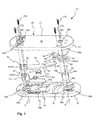
Fig. 1 anadapter 10 is shown, including acasing 20 and atransmission 50 which is suitable to use together with a lock case of a door. Thecasing 20 comprises acover portion 21 which comprises abase member 22 and aside member 23 surrounding thebase member 22 along its periphery and extending perpendicularly from saidbase member 22. Thebase member 22 and theside member 23 are in this case integrally formed and made in one piece, casted in preferably zinc. In an alternative embodiment thebase member 22 may be mounted, e.g. by welding, to one edge of theside member 23 such that they together may accommodate asupport portion 24. In another embodiment thebase member 22 and theside member 23 may made in one piece. Thecover portion 21 further includes a firstcircular opening 25a which is centered arranged about a fist axis A, and a secondcircular opening 26a which is centered arranged about a second axis B. The first opening 25a of thecover portion 21 corresponds to a first opening 25b of thesupport portion 24 which is also centered arranged about the first axis A. In the same way the second opening 26a of thecover portion 21 corresponds to a second opening 26b of thesupport portion 24 and centered arranged about the second axis B. - The
support portion 24 is preferably made in a solid piece which has the same outer shape and size as thebase member 22 of thecover portion 21. In an assembled state thebase member 22 and theside member 23 of thecover portion 21 enclose thesupport portion 24 with the exception of the rear outer surface of thesupport portion 24, adapted to be in close contact with the door. Thecover portion 21 and thesupport portion 24 are assembled by means of fastening means, in this case screws 27a-d which are inserted into threadedholes 28a-h in thecover portion 21 and thesupport portion 24. The twoportions - The
support portion 24 further comprises aspring recess 29 for receiving aspring 40 and at least one sensor recess 30a, 30b for receiving anelectronic sensor 41. Close to the second opening 26b of the support portion 24 acurved track 31 is arranged for receiving aguide member 57 which will be described further below. Therecesses track 31 may preferably be shaped by moulding or milling. - Accommodated within the
casing 20 is thespring 40, the optionalelectronic sensor 41, a door handle bushing 42 arranged with four outer grooves 43 a-d and a squarecentered opening 44 and a lock bushing 45 with twoouter grooves 46a-b and a rectangularcentered opening 47. In another embodiment theaxles handle bushing 42 is arranged in thefirst openings cover portion 21 and thesupport portion 24 and itssquare opening 44 is arranged to receive a handle follower which is connected to a handle on one side, in this case on the inside, of a door. The lock bushing 45 is arranged in thesecond openings cover portion 21 and thesupport portion 24 and itsrectangular opening 47 is arranged to receive a lock follower which is in operation with a lock bolt within the lock case. To be able to support the handle bushing 42 and the lock bushing 45 in their right places the first andsecond openings cover portion 21 andsupport portion 24, so that thebushing casing 20. The handle bushing 42 and the lock bushing 45 are however always free to rotate about the first and second axis A, B. - The
casing 20 further accommodates atransmission 50 including ahandle lever 51 which is provided with an opening 52 at its first end 53. The shape of theopening 52 corresponds to the outer shape of the handle bushing 42, where theopening 52 has fourprotrusion 54a-d which are configured to slide into theouter grooves 43a-d of the handle bushing 42 when assembling the twoparts handle lever 51 is connected to the handle bushing 42 in such a way that it is required to rotate with the handle bushing 42. Further, thehandle lever 51 has anelongated hole 54 on itsintermediate part 55 for receiving thespring 40 arranged in thespring recess 29. Thehandle lever 51 is, in an assembled state, located in an recess of thesupport portion 24 which allows thehandle lever 51 to rotate a certain number of degrees, preferably between 10° and 30° which corresponds to a normal movement a handle being pushed down, about the first axis A. In alternative embodiments the preferred degrees of rotation may be different depending on the features of the handle and door, e.g. in some embodiments the handle has to be rotated up to 360° which may lead to the adapter further including gear means (not shown). Thesecond end 55 of thehandle lever 51 has aside surface 56 which is allowed to engage with a guidingmember 57 and during rotation may push on the guidingmember 57 which is arranged to be guided in thecurved track 31. - Besides from the guiding
member 57 thetransmission 50 further includes alock lever 58 to which the guidingmember 57 is fixedly connected. In an alternative embodiment the guidingmember 57 and thelock lever 58 may be formed integrally and made in one piece and yet in another embodiment the guidingmember 57, thelock lever 58 and thelock bushing 45 may be made in one piece. Thelock lever 58 is at itsfirst end 59 provided with anopening 60 for receiving the guidingmember 57, the shape of the guidingmember 57 then should preferably correspond to the shape of theopening 60. Thefirst end 59 is slightly elevated relative to thesecond end 61 of thelock lever 58 so that e.g. thelock lever 58 does not risk to affect theside surface 56 of thehandle lever 51 as it rotates. In an alternative embodiment there is no elevation between the first end and the second end. - The
second end 61 of thelock lever 58 is provided with anopening 62 configured to receive thelock bushing 45. Theopening 62 has twoprotrusions 63a-b which corresponds to the twoouter grooves 46a-b of the lock bushing which together in an assembled state provides a strong connection for securing rotational fixation between thelock lever 58 and thelock axle 45. The appearances of thehandle bushing 42, thehandle lever 51, the guidingmember 57, thelock lever 58 and thelock bushing 45 may of course in other embodiments have another shape suitable for its purpose. These parts may preferably be made of plastic or metal. - In an alternative embodiment, e.g. where the adapter is arranged to a lock case in which the handle follower and the lock follower has the same rotational direction there may be a direct connection between the handle lever and the second end of the lock lever or the lock follower.
-
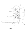
Fig. 2 shows theadapter 10 mounted to adoor leaf 70 and aninner handle 80, in a first idle state when thehandle 80 is in a resting position. Thishandle 80 is configured to be left hand rotated, if the handle is right hand rotated the appearance of theadapter 10 is inverted in relation to what is shown inFig. 2 . Thehandle 80 is connected to thehandle bushing 42 through an optional handle follower (not shown). Thehandle lever 51 is in an idle state resting against one side of the recess, in this case to the right. Thelock lever 61 and its guidingmember 57 are also located to the right in the idle state and in contact with theside surface 56 of thehandle lever 51. Thelock bushing 45 is connected to a biased lock follower (not shown) leading to alock bolt 81. -
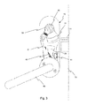
Fig. 3 then shows theadapter 10 in a second state where theinside door handle 70 has been pushed down. As soon as thehandle 70 is pushed down thehandle bushing 42 with thehandle lever 51 starts to rotate about the first axis A. Thesecond end 55 of thehandle lever 51 then starts to move towards the left side of the recess, pushing thefirst end 59 of thelock lever 58 and the guiding member in the same direction. As thehandle lever 51 rotates thespring 40 is strained. As thefirst end 59 of thelock lever 58 is pushed to one side thesecond end 61 and thelock bushing 45 starts to rotate about the second axis B, leading to rotation of the biased lock follower. Thelock bolt 81 is before rotation of the lock follower in an idle state protruding from thedoor leaf 70 leaving the door locked. When the lock follower rotates thelock bolt 81 is pulled into thedoor leaf 70 unlocking the door. - As soon as the person pushing the
handle 80 down lets go of it, it returns to its resting position, shown inFig. 2 , by means of thestrained spring 40 acting on thehandle lever 51. Thespring 40 pulls back thehandle lever 51 leading to thehandle bushing 42 rotating the handle follower and thehandle 80 back to its resting position. At the same time the biased lock follower rotates back to its idle state resulting in that thelock bolt 81 is pushed out of thedoor leaf 70 locking the door and that thelock bushing 45 andlock lever 58 returns the position shown inFig. 2 . - The rotation of the
handle lever 51 also affects the optionalelectronic sensor 41 which may be located in one of the twosensor recesses sensor 41 and thehandle lever 51 is broken or generated the sensor can send a signal to the, in this embodiment, an electronic locker which from the outside preferably is opened by means of a card or a code. Thesensor 41 may be used to by-pass a possible alarm or pass system when a person opens the door from the inside. - The
adapter 10 is detachable and preferably mounted in close contact with a door leaf on the inside, facing the room. Since it is detachable it is possible to mount theadapter 10 to an already existing lock case and also remove it if necessary which makes the installation easier for a mechanic. A door lock assembly including the lock case and the adapter is less sensitive to hard wear since the assembly is not dependent on small and narrow margins during operation, which leads to less breakage and maintenance than prior systems. If the assembly however needs maintenance work it is just to disassemble the adapter and perform necessary work on site. - An advantage with the present adapter is that it may be used on existing lock cases with no split spindle functionality. Hence, the present adapter may, together with such lock case without split spindle, replace spilt spindle lock cases for improving the reliability of the door lock thus always allowing persons on the inside of the locked door to exit the door.
- In an alternative embodiment the adapter may include an indicator (not shown) which is configured to indicate an active and/or inactive state of the adapter. The active state is when the components of the adapter are able to interact with each other so that locked door opens if the handle on one side is pressed down. The indicator is preferably an electrical indicator which indicates the active and/or inactive state with light, sound or movement. In an alternative embodiment it could be a mechanical indicator.
- It should be appreciated that even though numerous characteristics and advantages of the present invention have been set forth in the foregoing description, together with details of the structure and function of the invention, the description is only illustrative and changes may be made in detail, especially in matters of shape, size and arrangement of parts within the scope of the invention to the full extent indicated by the appended claims.
Claims (12)
1. An adapter for a lock case, comprising
a handle bushing (42) to be connected to a handle (80) and arranged to be rotated about a first axis (A) when the handle (80) is pushed down or pulled up for moving a latch bolt in and out from said lock case,
a lock bushing (45) to be connected to a lock follower extending through said lock case and arranged to rotate about a second axis (B) for moving a lock bolt (81) in and out from said lock case, and
a transmission (50) connecting said handle bushing (42) with said lock bushing (45) such that the lock bushing (45) is arranged to rotate in a first direction when the handle bushing (42) is rotated in a second direction being opposite said first direction.
2. The adapter according to claim 1, wherein the adapter (10) is adapted to be arranged on one side of a door, between a door leaf (70) and the door handle (80), wherein said lock case is inserted into a recess of said door.
3. The adapter according to claim 2, wherein the adapter (10) is adapted to be detachable from said door.
4. The adapter according to any one of the claims 1-3, wherein the transmission (50) comprises a handle lever (51) connected to the handle bushing (42), and a lock lever (58) which is connected to the lock bushing (45) and which is in constant contact with the handle lever (51) such that the lock lever (58) always rotates with the handle lever (51).
5. The adapter according to claim 4, wherein the handle lever (51) is biased such that it automatically returns to an idle state, corresponding to a horizontally aligned position of the door handle (80), when a force for pushing down the door handle (80) has been released.
5. The adapter according to claim 4 or 5, wherein the handle lever (51) is arranged to push on the lock lever (58) as it rotates with the handle bushing (42) about the first axis (A), affecting the lock lever (58) and the lock follower to rotate about the second axis (B).
6. The adapter according to any one of the claims 1-6, further comprising a casing (20) including a cover portion (21) and a support portion (24) which are connected by fastening means (27a-d).
7. The adapter according to claim 7, wherein the support portion (24) comprises a track (31) in which the lock lever (58) is guided when it rotates about the second axis (B).
8. The adapter according to any one of the preceding claims, further comprising an indicator configured to indicate an active and/or inactive state of said adapter.
9. The adapter according to claim 8, wherein the indicator is an electrical indicator.
10. A door lock assembly for mounting to a door leaf, comprising
a lock case including a latch bolt to be operated by at least one door handle (80) connected to a door handle follower of said lock case,
a lock bolt (81) in connection with a lock follower (not shown) of said lock case, and
an adapter according to any of the preceding claims connected to said lock case.
11. A door comprising a door lock assembly according to claim 10.
Priority Applications (4)
| Application Number | Priority Date | Filing Date | Title |
|---|---|---|---|
| EP13177440.8A EP2829673A1 (en) | 2013-07-22 | 2013-07-22 | An adapter for a lock case |
| DK14178031.2T DK2829674T3 (en) | 2013-07-22 | 2014-07-22 | ADAPT TO A LOCK BOX |
| EP14178031.2A EP2829674B1 (en) | 2013-07-22 | 2014-07-22 | Adapter for a lock case |
| NO14178031A NO2829674T3 (en) | 2013-07-22 | 2014-07-22 |
Applications Claiming Priority (1)
| Application Number | Priority Date | Filing Date | Title |
|---|---|---|---|
| EP13177440.8A EP2829673A1 (en) | 2013-07-22 | 2013-07-22 | An adapter for a lock case |
Publications (1)
| Publication Number | Publication Date |
|---|---|
| EP2829673A1 true EP2829673A1 (en) | 2015-01-28 |
Family
ID=48875540
Family Applications (2)
| Application Number | Title | Priority Date | Filing Date |
|---|---|---|---|
| EP13177440.8A Withdrawn EP2829673A1 (en) | 2013-07-22 | 2013-07-22 | An adapter for a lock case |
| EP14178031.2A Not-in-force EP2829674B1 (en) | 2013-07-22 | 2014-07-22 | Adapter for a lock case |
Family Applications After (1)
| Application Number | Title | Priority Date | Filing Date |
|---|---|---|---|
| EP14178031.2A Not-in-force EP2829674B1 (en) | 2013-07-22 | 2014-07-22 | Adapter for a lock case |
Country Status (3)
| Country | Link |
|---|---|
| EP (2) | EP2829673A1 (en) |
| DK (1) | DK2829674T3 (en) |
| NO (1) | NO2829674T3 (en) |
Cited By (3)
| Publication number | Priority date | Publication date | Assignee | Title |
|---|---|---|---|---|
| CN107975305A (en) * | 2016-10-25 | 2018-05-01 | 德金属工业股份有限公司 | Inside operating device for door lock |
| CN109736637A (en) * | 2019-03-20 | 2019-05-10 | 冰山松洋生物科技(大连)有限公司 | Enabling labour-saving door handle structure |
| GR1009997B (en) * | 2020-07-14 | 2021-05-07 | Πλαστικα Νοτιοανατολικης Ευρωπης-Μονοπροσωπη Εταιρεια Περιορισμενης Ευθυνης | Adapter for the handle's mounting center transfer |
Families Citing this family (2)
| Publication number | Priority date | Publication date | Assignee | Title |
|---|---|---|---|---|
| SE545946C2 (en) * | 2020-06-12 | 2024-03-19 | Stendals El Ab | Adapter for a locking device for unlocking by an inner handle in an emergency function |
| FR3158977A1 (en) * | 2024-02-05 | 2025-08-08 | Ferco | Locking hardware control device |
Citations (5)
| Publication number | Priority date | Publication date | Assignee | Title |
|---|---|---|---|---|
| US3875772A (en) * | 1973-11-28 | 1975-04-08 | Nat Hardware Co Inc | Door latch and anti panic dead bolt lock |
| US4183563A (en) * | 1977-11-25 | 1980-01-15 | Scovill Manufacturing Company | Panic-proof lockset |
| DE19604442A1 (en) * | 1995-02-07 | 1996-08-08 | Talleres Escoriaza Sa | Security device for electronic locks |
| US20040107747A1 (en) * | 2002-12-09 | 2004-06-10 | Shih-Chung Chang | Linkage adapted to be controlled by an inner handle to deactivate a primary dead bolt which is controlled by a knob on a door |
| US20110314876A1 (en) * | 2010-06-29 | 2011-12-29 | Guan-Chen Fang | Locking Assembly for a Door |
Family Cites Families (3)
| Publication number | Priority date | Publication date | Assignee | Title |
|---|---|---|---|---|
| US4129019A (en) * | 1977-05-16 | 1978-12-12 | Schlage Lock Company | Cartridge for a lockset |
| US4276760A (en) * | 1979-10-22 | 1981-07-07 | Nolin Roger J | Two-bolt lockset with simultaneous locking and unlocking of its bolts |
| US7363784B2 (en) * | 2005-02-28 | 2008-04-29 | Assa Abloy, Inc. | Independently interactive interconnected lock |
-
2013
- 2013-07-22 EP EP13177440.8A patent/EP2829673A1/en not_active Withdrawn
-
2014
- 2014-07-22 EP EP14178031.2A patent/EP2829674B1/en not_active Not-in-force
- 2014-07-22 DK DK14178031.2T patent/DK2829674T3/en active
- 2014-07-22 NO NO14178031A patent/NO2829674T3/no unknown
Patent Citations (5)
| Publication number | Priority date | Publication date | Assignee | Title |
|---|---|---|---|---|
| US3875772A (en) * | 1973-11-28 | 1975-04-08 | Nat Hardware Co Inc | Door latch and anti panic dead bolt lock |
| US4183563A (en) * | 1977-11-25 | 1980-01-15 | Scovill Manufacturing Company | Panic-proof lockset |
| DE19604442A1 (en) * | 1995-02-07 | 1996-08-08 | Talleres Escoriaza Sa | Security device for electronic locks |
| US20040107747A1 (en) * | 2002-12-09 | 2004-06-10 | Shih-Chung Chang | Linkage adapted to be controlled by an inner handle to deactivate a primary dead bolt which is controlled by a knob on a door |
| US20110314876A1 (en) * | 2010-06-29 | 2011-12-29 | Guan-Chen Fang | Locking Assembly for a Door |
Cited By (5)
| Publication number | Priority date | Publication date | Assignee | Title |
|---|---|---|---|---|
| CN107975305A (en) * | 2016-10-25 | 2018-05-01 | 德金属工业股份有限公司 | Inside operating device for door lock |
| CN107975305B (en) * | 2016-10-25 | 2020-03-10 | 一德金属工业股份有限公司 | Inside operating device for door lock |
| CN109736637A (en) * | 2019-03-20 | 2019-05-10 | 冰山松洋生物科技(大连)有限公司 | Enabling labour-saving door handle structure |
| GR1009997B (en) * | 2020-07-14 | 2021-05-07 | Πλαστικα Νοτιοανατολικης Ευρωπης-Μονοπροσωπη Εταιρεια Περιορισμενης Ευθυνης | Adapter for the handle's mounting center transfer |
| EP3940175A1 (en) | 2020-07-14 | 2022-01-19 | Seu Plastics One Man L.L.C. | Adaptor for handle installation transposition |
Also Published As
| Publication number | Publication date |
|---|---|
| EP2829674B1 (en) | 2017-09-27 |
| NO2829674T3 (en) | 2018-02-24 |
| EP2829674A1 (en) | 2015-01-28 |
| DK2829674T3 (en) | 2018-01-08 |
Similar Documents
| Publication | Publication Date | Title |
|---|---|---|
| EP2829673A1 (en) | An adapter for a lock case | |
| US9580931B2 (en) | Mortise lock apparatus and electronic operating system | |
| US5925861A (en) | Security door lock arrangement with magnetically operated switch in the closed door position | |
| RU2633237C2 (en) | Door lock of vehicle | |
| CA2789888A1 (en) | Electronic cabinet/drawer lock system | |
| KR102469235B1 (en) | Latches and latch systems with indicators | |
| JP6820436B2 (en) | Push rod locks for switch cabinet enclosures, corresponding devices, and corresponding methods | |
| US11866962B2 (en) | Security locking assembly for shipping container doors | |
| US20190330887A1 (en) | Security locking assembly for shipping container doors | |
| EP2592203A2 (en) | Lock | |
| US9222281B2 (en) | Self-adjusting cylinder monitor assembly | |
| US7673481B2 (en) | Key safe apparatus and method | |
| US20140331723A1 (en) | Electronic Locking Device | |
| US12571932B2 (en) | Window locking device and system | |
| US20250230685A1 (en) | Assembly, system, and method for operatively associating a smart lock to a barrier | |
| GB2502860A (en) | Locking arrangement comprising two releasable positions for a striker | |
| US20070157431A1 (en) | Hinge with built in safety switch | |
| KR101700387B1 (en) | An Electric Type of Locking Device Having A Structure of Sliding Open and Shut | |
| CN110939317B (en) | Control handle with entry monitoring system | |
| DE102017128411B4 (en) | Door guard device | |
| JP7728570B2 (en) | Fastening structure and object detection device equipped with said structure | |
| EP4234850B1 (en) | A door handle arrangement | |
| CN110118035B (en) | Switch cabinet ground knife hole lockset | |
| JP2005068731A (en) | Crescent lock | |
| WO2016134724A1 (en) | Locking system |
Legal Events
| Date | Code | Title | Description |
|---|---|---|---|
| 17P | Request for examination filed |
Effective date: 20130722 |
|
| AK | Designated contracting states |
Kind code of ref document: A1 Designated state(s): AL AT BE BG CH CY CZ DE DK EE ES FI FR GB GR HR HU IE IS IT LI LT LU LV MC MK MT NL NO PL PT RO RS SE SI SK SM TR |
|
| AX | Request for extension of the european patent |
Extension state: BA ME |
|
| PUAI | Public reference made under article 153(3) epc to a published international application that has entered the european phase |
Free format text: ORIGINAL CODE: 0009012 |
|
| STAA | Information on the status of an ep patent application or granted ep patent |
Free format text: STATUS: THE APPLICATION IS DEEMED TO BE WITHDRAWN |
|
| 18D | Application deemed to be withdrawn |
Effective date: 20150729 |