EP2829489A1 - Snap fastener - Google Patents
Snap fastener Download PDFInfo
- Publication number
- EP2829489A1 EP2829489A1 EP13874856.1A EP13874856A EP2829489A1 EP 2829489 A1 EP2829489 A1 EP 2829489A1 EP 13874856 A EP13874856 A EP 13874856A EP 2829489 A1 EP2829489 A1 EP 2829489A1
- Authority
- EP
- European Patent Office
- Prior art keywords
- disc
- engaging cylinder
- retaining element
- fastener
- engagement structure
- Prior art date
- Legal status (The legal status is an assumption and is not a legal conclusion. Google has not performed a legal analysis and makes no representation as to the accuracy of the status listed.)
- Withdrawn
Links
- 230000002093 peripheral effect Effects 0.000 claims abstract description 4
- 239000011111 cardboard Substances 0.000 claims description 13
- 239000011087 paperboard Substances 0.000 description 22
- 230000008878 coupling Effects 0.000 description 7
- 238000010168 coupling process Methods 0.000 description 7
- 238000005859 coupling reaction Methods 0.000 description 7
- 238000009958 sewing Methods 0.000 description 5
- 238000012986 modification Methods 0.000 description 1
- 230000004048 modification Effects 0.000 description 1
- 238000012856 packing Methods 0.000 description 1
Images

Classifications
-
- A—HUMAN NECESSITIES
- A44—HABERDASHERY; JEWELLERY
- A44B—BUTTONS, PINS, BUCKLES, SLIDE FASTENERS, OR THE LIKE
- A44B17/00—Press-button or snap fasteners
- A44B17/0047—Press-button fasteners consisting of three parts
-
- F—MECHANICAL ENGINEERING; LIGHTING; HEATING; WEAPONS; BLASTING
- F16—ENGINEERING ELEMENTS AND UNITS; GENERAL MEASURES FOR PRODUCING AND MAINTAINING EFFECTIVE FUNCTIONING OF MACHINES OR INSTALLATIONS; THERMAL INSULATION IN GENERAL
- F16B—DEVICES FOR FASTENING OR SECURING CONSTRUCTIONAL ELEMENTS OR MACHINE PARTS TOGETHER, e.g. NAILS, BOLTS, CIRCLIPS, CLAMPS, CLIPS OR WEDGES; JOINTS OR JOINTING
- F16B5/00—Joining sheets or plates, e.g. panels, to one another or to strips or bars parallel to them
- F16B5/06—Joining sheets or plates, e.g. panels, to one another or to strips or bars parallel to them by means of clamps or clips
- F16B5/0607—Joining sheets or plates, e.g. panels, to one another or to strips or bars parallel to them by means of clamps or clips joining sheets or plates to each other
- F16B5/0621—Joining sheets or plates, e.g. panels, to one another or to strips or bars parallel to them by means of clamps or clips joining sheets or plates to each other in parallel relationship
- F16B5/0642—Joining sheets or plates, e.g. panels, to one another or to strips or bars parallel to them by means of clamps or clips joining sheets or plates to each other in parallel relationship the plates being arranged one on top of the other and in full close contact with each other
-
- A—HUMAN NECESSITIES
- A44—HABERDASHERY; JEWELLERY
- A44B—BUTTONS, PINS, BUCKLES, SLIDE FASTENERS, OR THE LIKE
- A44B17/00—Press-button or snap fasteners
- A44B17/0023—Press-button fasteners in which the elastic retaining action is obtained by the own elasticity of the material constituting the fastener
-
- F—MECHANICAL ENGINEERING; LIGHTING; HEATING; WEAPONS; BLASTING
- F16—ENGINEERING ELEMENTS AND UNITS; GENERAL MEASURES FOR PRODUCING AND MAINTAINING EFFECTIVE FUNCTIONING OF MACHINES OR INSTALLATIONS; THERMAL INSULATION IN GENERAL
- F16B—DEVICES FOR FASTENING OR SECURING CONSTRUCTIONAL ELEMENTS OR MACHINE PARTS TOGETHER, e.g. NAILS, BOLTS, CIRCLIPS, CLAMPS, CLIPS OR WEDGES; JOINTS OR JOINTING
- F16B21/00—Means for preventing relative axial movement of a pin, spigot, shaft or the like and a member surrounding it; Stud-and-socket releasable fastenings
- F16B21/06—Releasable fastening devices with snap-action
- F16B21/07—Releasable fastening devices with snap-action in which the socket has a resilient part
- F16B21/073—Releasable fastening devices with snap-action in which the socket has a resilient part the socket having a resilient part on its inside
-
- F—MECHANICAL ENGINEERING; LIGHTING; HEATING; WEAPONS; BLASTING
- F16—ENGINEERING ELEMENTS AND UNITS; GENERAL MEASURES FOR PRODUCING AND MAINTAINING EFFECTIVE FUNCTIONING OF MACHINES OR INSTALLATIONS; THERMAL INSULATION IN GENERAL
- F16B—DEVICES FOR FASTENING OR SECURING CONSTRUCTIONAL ELEMENTS OR MACHINE PARTS TOGETHER, e.g. NAILS, BOLTS, CIRCLIPS, CLAMPS, CLIPS OR WEDGES; JOINTS OR JOINTING
- F16B43/00—Washers or equivalent devices; Other devices for supporting bolt-heads or nuts
-
- Y—GENERAL TAGGING OF NEW TECHNOLOGICAL DEVELOPMENTS; GENERAL TAGGING OF CROSS-SECTIONAL TECHNOLOGIES SPANNING OVER SEVERAL SECTIONS OF THE IPC; TECHNICAL SUBJECTS COVERED BY FORMER USPC CROSS-REFERENCE ART COLLECTIONS [XRACs] AND DIGESTS
- Y10—TECHNICAL SUBJECTS COVERED BY FORMER USPC
- Y10T—TECHNICAL SUBJECTS COVERED BY FORMER US CLASSIFICATION
- Y10T24/00—Buckles, buttons, clasps, etc.
- Y10T24/44—Clasp, clip, support-clamp, or required component thereof
- Y10T24/44017—Clasp, clip, support-clamp, or required component thereof with specific mounting means for attaching to rigid or semirigid supporting structure or structure-to-be-secured
- Y10T24/44026—Clasp, clip, support-clamp, or required component thereof with specific mounting means for attaching to rigid or semirigid supporting structure or structure-to-be-secured for cooperating with aperture in supporting structure or structure-to-be-secured
Definitions
- the present invention relates to a connecting member for a package box, and more particularly to a fastener assembly for sewing a cardboard or a wooden board of the package box.
- a conventional package box is made of a cardboard to package and protect commodities during delivery.
- a connecting screw disclosed in CN Patent No. 101966881A is employed to sewing the package box and contains a body, a hexagon extension, a first coupling member, a second coupling member, and a third coupling member.
- the body is riveted with the first coupling member to form a first connection unit
- the third coupling member is screwed with a hexagon nut of the hexagon extension to form the second connection unit.
- the first connection unit is placed on the inner paper board, and at least one tip tooth of the first coupling member pierces into the inner paper board, the second connection unit is fixed on the outer paper board, the second coupling member retains with the body and is defined between the inner paper board and the outer paper board, and a free end of the hexagon extension screws with the body so that the inner paper board and the outer paper board are sewed together.
- the inner paper board and the outer paper board are sewed together by ways of the hexagon extension and the body, so a tool, such as a Phillips screwdriver, a wrench, or pliers, has to be used to operate the hexagon extension and the body, thus causing troublesome operation.
- the present invention has arisen to mitigate and/or obviate the afore-described disadvantages.
- the primary object of the present invention is to provide a fastener assembly in which a main fastener and an auxiliary fastener are placed on an inner paper board ad an outer paper board of a cardboard, and a second disc is defined between the inner paper board and the outer paper board, thereafter the auxiliary fastener is pressed to fasten with the main fastener easily.
- Further object of the present invention is to provide a fastener assembly which is simplified and manufactured easily.
- Another object of the present invention is to provide a fastener assembly which is applicable for sewing a cardboard or a wooden board of a package box.
- a fastener assembly provided by the present invention contains: a first disc with a plurality of tip teeth, an engaging cylinder, a second disc, a retaining element, and a third dis.
- the engaging cylinder is hollow and includes a first engagement structure formed on an inner wall thereof, and the engaging cylinder is connected with the first disc to form a main fastener.
- the second disc includes a through hole defined on a central position thereof and plural recesses radially extending from a peripheral side of the through hole, wherein the engaging cylinder inserts through and retains with the through hole of the second disc so that the engaging cylinder engages with the second disc.
- the retaining element is cylindrical or columnar and includes a second engagement structure arranged on a first end thereof, wherein a second end of the retaining element is coupled with the third disc to form an auxiliary fastener.
- the first end of the retaining element is inserted into the engaging cylinder so that the first engagement structure engages with the second engagement structure, thus retaining the main fastener with the auxiliary fastener.
- the first engagement structure has plural elongated orifices defined on an outer wall of the engaging cylinder and plural flexible slats extending to the inner wall of the engaging cylinder from the plural elongated orifices, and a first end of each flexible slat adjacent to the first disc is a free end and extends into the engaging cylinder to engage with the retaining element, a second end of each flexible slat is one piece formed with the engaging cylinder.
- a number of the plural flexible slats is at least one.
- the second engagement structure has a snap portion radially extending from the first end of the retaining element and a conical section defined between the snap portion and the second end of the retaining element; the snap portion is formed in a conical disk shape and has a small-diameter segment arranged on the first end of the retaining element to insert into the engaging cylinder; or the snap portion is formed in a conical post shape and has the small-diameter segment arranged on the first end of the retaining element to insert into and retain with the engaging cylinder, such that when the retaining element is inserted into the engaging cylinder, a gap is formed between the conical section and the inner wall of the engaging cylinder so that the two flexible slats insert into the engaging cylinder to retain with the snap portion.
- a number of the plurality of tip teeth is at least four tip teeth symmetrically arranged on the first disc.
- the first disc also includes plural fixing apertures for removing the first disc from the cardboard easily.
- a fastener assembly comprises: a first disc 1 with a plurality of tip teeth 2, an engaging cylinder 4, a second disc 7, a retaining element 9, and a third disc 13.
- the engaging cylinder 4 is hollow and includes a first engagement structure formed on an inner wall thereof, and the engaging cylinder 4 is connected with the first disc 1 to form a main fastener.
- the second disc 7 includes a through hole 8 defined on a central position thereof and plural recesses radially extending from a peripheral side of the through hole 8, wherein the engaging cylinder 4 inserts through and retains with the through hole 8 of the second disc 7 so that the engaging cylinder 4 engages with the second disc 7.
- the retaining element 9 is cylindrical or columnar and includes a second engagement structure arranged on a first end thereof, wherein a second end of the retaining element 9 is coupled with the third disc 13 to form an auxiliary fastener, and the first end of the retaining element 9 is inserted into the engaging cylinder 4 so that the first engagement structure engages with the second engagement structure, thus retaining the main fastener with the auxiliary fastener.
- the first engagement structure has plural elongated orifices 5 defined on an outer wall of the engaging cylinder 4 and plural flexible slats 6 extending to the inner wall of the engaging cylinder 4 from the plural elongated orifices 5, wherein a length of each elongated orifice 5 is equal to that of each flexible slat 6, and a first end of each flexible slat 6 adjacent to the first disc 1 is a free end and extends into the engaging cylinder 4 to engage with the retaining element 9, a second end of each flexible slat 6 is one piece formed with the engaging cylinder 4.
- a number of the plural flexible slats 6 is two, and two flexible slats 6 are symmetrically one piece formed with the engaging cylinder 4 and extending into the engaging cylinder 4 at a same depth.
- the second engagement structure has a snap portion 10 radially extending from the first end of the retaining element 9 and a conical section 12 defined between the snap portion 10 and the second end of the retaining element 9.
- the snap portion 10 is formed in a conical disk shape and has a small-diameter segment 11 arranged on the first end of the retaining element 9 to insert into the engaging cylinder 4; or the snap portion 10 is formed in a conical post shape and has the small-diameter segment 11 arranged on the first end of the retaining element 9 to insert into and retain with the engaging cylinder 4, such that when the retaining element 9 is inserted into the engaging cylinder 4, a gap is formed between the conical section 12 and the inner wall of the engaging cylinder 4 so that the two flexible slats 6 insert into the engaging cylinder 4 to retain with the snap portion 10.
- a number of the plurality of tip teeth 2 is at least four tip teeth symmetrically arranged on the first disc 1 and piercing into a cardboard to position the first disc 1 and the cardboard together.
- the first disc 1 also includes plural fixing apertures 3 for removing the first disc 1 from the cardboard easily.
- the main fastener and the auxiliary fastener are placed on an inner paper board and an outer paper board of the cardboard so that the first disc 1 of the main fastener is fixed on the inner paper board, and the plurality of tip teeth 2 of the first disc 1 pierces into the inner paper board, the third disc 13 of the auxiliary fastener is mounted on the outer paper board, the second disc 7 is defined between the inner paper board and the outer paper board, thereafter the auxiliary fastener is pressed to fasten with the main fastener.
- the fastener assembly of the present invention is also applicable for a wooden board of the package box.
Landscapes
- Engineering & Computer Science (AREA)
- General Engineering & Computer Science (AREA)
- Mechanical Engineering (AREA)
- Cartons (AREA)
Abstract
Description
- The present invention relates to a connecting member for a package box, and more particularly to a fastener assembly for sewing a cardboard or a wooden board of the package box.
- A conventional package box is made of a cardboard to package and protect commodities during delivery.
- A connecting screw disclosed in
CN Patent No. 101966881A is employed to sewing the package box and contains a body, a hexagon extension, a first coupling member, a second coupling member, and a third coupling member. The body is riveted with the first coupling member to form a first connection unit, and the third coupling member is screwed with a hexagon nut of the hexagon extension to form the second connection unit. As sewing an inner paper board and an outer paper board of the cardboard, the first connection unit is placed on the inner paper board, and at least one tip tooth of the first coupling member pierces into the inner paper board, the second connection unit is fixed on the outer paper board, the second coupling member retains with the body and is defined between the inner paper board and the outer paper board, and a free end of the hexagon extension screws with the body so that the inner paper board and the outer paper board are sewed together. - However, the inner paper board and the outer paper board are sewed together by ways of the hexagon extension and the body, so a tool, such as a Phillips screwdriver, a wrench, or pliers, has to be used to operate the hexagon extension and the body, thus causing troublesome operation.
- Furthermore, as packing or unpacking the cardboard, the tool for screwing or unscrewing the hexagon extension is required, thereby increasing operation cost.
- The present invention has arisen to mitigate and/or obviate the afore-described disadvantages.
- The primary object of the present invention is to provide a fastener assembly in which a main fastener and an auxiliary fastener are placed on an inner paper board ad an outer paper board of a cardboard, and a second disc is defined between the inner paper board and the outer paper board, thereafter the auxiliary fastener is pressed to fasten with the main fastener easily.
- Further object of the present invention is to provide a fastener assembly which is simplified and manufactured easily.
- Another object of the present invention is to provide a fastener assembly which is applicable for sewing a cardboard or a wooden board of a package box.
- A fastener assembly provided by the present invention contains: a first disc with a plurality of tip teeth, an engaging cylinder, a second disc, a retaining element, and a third dis.
- The engaging cylinder is hollow and includes a first engagement structure formed on an inner wall thereof, and the engaging cylinder is connected with the first disc to form a main fastener.
- The second disc includes a through hole defined on a central position thereof and plural recesses radially extending from a peripheral side of the through hole, wherein the engaging cylinder inserts through and retains with the through hole of the second disc so that the engaging cylinder engages with the second disc.
- The retaining element is cylindrical or columnar and includes a second engagement structure arranged on a first end thereof, wherein a second end of the retaining element is coupled with the third disc to form an auxiliary fastener.
- The first end of the retaining element is inserted into the engaging cylinder so that the first engagement structure engages with the second engagement structure, thus retaining the main fastener with the auxiliary fastener.
- Preferably, the first engagement structure has plural elongated orifices defined on an outer wall of the engaging cylinder and plural flexible slats extending to the inner wall of the engaging cylinder from the plural elongated orifices, and a first end of each flexible slat adjacent to the first disc is a free end and extends into the engaging cylinder to engage with the retaining element, a second end of each flexible slat is one piece formed with the engaging cylinder.
- Preferably, a number of the plural flexible slats is at least one.
- Preferably, the second engagement structure has a snap portion radially extending from the first end of the retaining element and a conical section defined between the snap portion and the second end of the retaining element; the snap portion is formed in a conical disk shape and has a small-diameter segment arranged on the first end of the retaining element to insert into the engaging cylinder; or the snap portion is formed in a conical post shape and has the small-diameter segment arranged on the first end of the retaining element to insert into and retain with the engaging cylinder, such that when the retaining element is inserted into the engaging cylinder, a gap is formed between the conical section and the inner wall of the engaging cylinder so that the two flexible slats insert into the engaging cylinder to retain with the snap portion.
- Preferably, a number of the plurality of tip teeth is at least four tip teeth symmetrically arranged on the first disc.
- Preferably, the first disc also includes plural fixing apertures for removing the first disc from the cardboard easily.
-
-
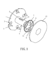
FIG. 1 is a perspective view showing the exploded components of a fastener assembly according to a preferred embodiment of the present invention. -
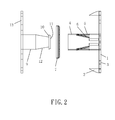
FIG. 2 is a side plan view showing the exploded components of the fastener assembly according to the preferred embodiment of the present invention. -
FIG. 3 is a perspective view showing the assembly of the fastener assembly according to the preferred embodiment of the present invention. -
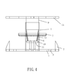
FIG. 4 is a side plan view showing the assembly of the fastener assembly according to the preferred embodiment of the present invention. - With reference to
FIGS. 1 to 4 , a fastener assembly according to a preferred embodiment of the present invention comprises: afirst disc 1 with a plurality oftip teeth 2, anengaging cylinder 4, asecond disc 7, aretaining element 9, and athird disc 13. Theengaging cylinder 4 is hollow and includes a first engagement structure formed on an inner wall thereof, and theengaging cylinder 4 is connected with thefirst disc 1 to form a main fastener. Thesecond disc 7 includes a throughhole 8 defined on a central position thereof and plural recesses radially extending from a peripheral side of the throughhole 8, wherein theengaging cylinder 4 inserts through and retains with the throughhole 8 of thesecond disc 7 so that theengaging cylinder 4 engages with thesecond disc 7. Theretaining element 9 is cylindrical or columnar and includes a second engagement structure arranged on a first end thereof, wherein a second end of theretaining element 9 is coupled with thethird disc 13 to form an auxiliary fastener, and the first end of theretaining element 9 is inserted into theengaging cylinder 4 so that the first engagement structure engages with the second engagement structure, thus retaining the main fastener with the auxiliary fastener. - The first engagement structure has plural
elongated orifices 5 defined on an outer wall of theengaging cylinder 4 and pluralflexible slats 6 extending to the inner wall of theengaging cylinder 4 from the pluralelongated orifices 5, wherein a length of eachelongated orifice 5 is equal to that of eachflexible slat 6, and a first end of eachflexible slat 6 adjacent to thefirst disc 1 is a free end and extends into theengaging cylinder 4 to engage with theretaining element 9, a second end of eachflexible slat 6 is one piece formed with theengaging cylinder 4. - In this embodiment, a number of the plural
flexible slats 6 is two, and twoflexible slats 6 are symmetrically one piece formed with theengaging cylinder 4 and extending into theengaging cylinder 4 at a same depth. - The second engagement structure has a
snap portion 10 radially extending from the first end of theretaining element 9 and aconical section 12 defined between thesnap portion 10 and the second end of theretaining element 9. Thesnap portion 10 is formed in a conical disk shape and has a small-diameter segment 11 arranged on the first end of theretaining element 9 to insert into theengaging cylinder 4; or thesnap portion 10 is formed in a conical post shape and has the small-diameter segment 11 arranged on the first end of the retainingelement 9 to insert into and retain with theengaging cylinder 4, such that when theretaining element 9 is inserted into theengaging cylinder 4, a gap is formed between theconical section 12 and the inner wall of theengaging cylinder 4 so that the twoflexible slats 6 insert into theengaging cylinder 4 to retain with thesnap portion 10. - Preferably, a number of the plurality of
tip teeth 2 is at least four tip teeth symmetrically arranged on thefirst disc 1 and piercing into a cardboard to position thefirst disc 1 and the cardboard together. - The
first disc 1 also includesplural fixing apertures 3 for removing thefirst disc 1 from the cardboard easily. - Thereby, when sewing a package box of the cardboard, the main fastener and the auxiliary fastener are placed on an inner paper board and an outer paper board of the cardboard so that the
first disc 1 of the main fastener is fixed on the inner paper board, and the plurality oftip teeth 2 of thefirst disc 1 pierces into the inner paper board, thethird disc 13 of the auxiliary fastener is mounted on the outer paper board, thesecond disc 7 is defined between the inner paper board and the outer paper board, thereafter the auxiliary fastener is pressed to fasten with the main fastener. - Preferably, the fastener assembly of the present invention is also applicable for a wooden board of the package box.
- While the preferred embodiments of the invention have been set forth for the purpose of disclosure, modifications of the disclosed embodiments of the invention as well as other embodiments thereof may occur to those skilled in the art. Accordingly, the appended claims are intended to cover all embodiments which do not depart from the spirit and scope of the invention.
Claims (6)
- A fastener assembly comprising:a first disc with a plurality of tip teeth, an engaging cylinder, a second disc, a retaining element, and a third disc, characterized in that:the engaging cylinder is hollow and includes a first engagement structure formed on an inner wall thereof, and the engaging cylinder is connected with the first disc to form a main fastener;the second disc includes a through hole defined on a central position thereof and plural recesses radially extending from a peripheral side of the through hole, wherein the engaging cylinder inserts through and retains with the through hole of the second disc so that the engaging cylinder engages with the second disc;the retaining element is cylindrical or columnar and includes a second engagement structure arranged on a first end thereof, wherein a second end of the retaining element is coupled with the third disc to form an auxiliary fastener;the first end of the retaining element is inserted into the engaging cylinder so that the first engagement structure engages with the second engagement structure, thus retaining the main fastener with the auxiliary fastener.
- The fastener assembly as claimed in claim 1, characterized in that the first engagement structure has plural elongated orifices defined on an outer wall of the engaging cylinder and plural flexible slats extending to the inner wall of the engaging cylinder from the plural elongated orifices, and a first end of each flexible slat adjacent to the first disc is a free end and extends into the engaging cylinder to engage with the retaining element, a second end of each flexible slat is one piece formed with the engaging cylinder.
- The fastener assembly as claimed in claim 2, characterized in that a number of the plural flexible slats is at least one.
- The fastener assembly as claimed in claim 1, characterized in that the second engagement structure has a snap portion radially extending from the first end of the retaining element and a conical section defined between the snap portion and the second end of the retaining element; the snap portion is formed in a conical disk shape and has a small-diameter segment arranged on the first end of the retaining element to insert into the engaging cylinder; or the snap portion is formed in a conical post shape and has the small-diameter segment arranged on the first end of the retaining element to insert into and retain with the engaging cylinder, such that when the retaining element is inserted into the engaging cylinder, a gap is formed between the conical section and the inner wall of the engaging cylinder so that the two flexible slats insert into the engaging cylinder to retain with the snap portion.
- The fastener assembly as claimed in claim 1, characterized in that a number of the plurality of tip teeth is at least four tip teeth symmetrically arranged on the first disc.
- The fastener assembly as claimed in claim 1, characterized in that the first disc also includes plural fixing apertures for removing the first disc from the cardboard easily.
Applications Claiming Priority (2)
| Application Number | Priority Date | Filing Date | Title |
|---|---|---|---|
| CN201310143824.XA CN103204302B (en) | 2013-04-24 | 2013-04-24 | Primary and secondary fastener |
| PCT/CN2013/077432 WO2014172975A1 (en) | 2013-04-24 | 2013-06-19 | Snap fastener |
Publications (2)
| Publication Number | Publication Date |
|---|---|
| EP2829489A1 true EP2829489A1 (en) | 2015-01-28 |
| EP2829489A4 EP2829489A4 (en) | 2016-03-02 |
Family
ID=48751756
Family Applications (1)
| Application Number | Title | Priority Date | Filing Date |
|---|---|---|---|
| EP13874856.1A Withdrawn EP2829489A4 (en) | 2013-04-24 | 2013-06-19 | Snap fastener |
Country Status (7)
| Country | Link |
|---|---|
| US (1) | US9538815B2 (en) |
| EP (1) | EP2829489A4 (en) |
| JP (1) | JP2016520485A (en) |
| KR (1) | KR20160003064A (en) |
| CN (1) | CN103204302B (en) |
| AU (1) | AU2013387458A1 (en) |
| WO (1) | WO2014172975A1 (en) |
Cited By (1)
| Publication number | Priority date | Publication date | Assignee | Title |
|---|---|---|---|---|
| US20180217641A1 (en) * | 2017-01-30 | 2018-08-02 | Fujitsu Limited | Casing Closure For A Casing Of An Electronic Device And Its Use |
Families Citing this family (15)
| Publication number | Priority date | Publication date | Assignee | Title |
|---|---|---|---|---|
| DK178327B1 (en) * | 2015-03-17 | 2015-12-14 | Hugo Grønlund | Interlocking assembly |
| CN205780138U (en) * | 2016-07-07 | 2016-12-07 | 朱震球 | A kind of bracing type connection clip |
| CN106015246A (en) * | 2016-08-10 | 2016-10-12 | 上汽通用五菱汽车股份有限公司 | Snap fastener and metal plate |
| CN106428894B (en) * | 2016-11-21 | 2018-09-28 | 重庆优优新材料有限公司 | A kind of junction button for packing articles |
| FR3059062B1 (en) * | 2016-11-22 | 2019-07-19 | Airbus Operations | SELF-PROPELLED INSULATION MATTRESS FOR AIRCRAFT INSULATION MATTRESS, METHOD OF INSTALLING SAID SPACER AND AIRCRAFT INSULATION MATTRESS EQUIPPED WITH SAID SPACER |
| CN107559287B (en) * | 2017-09-20 | 2023-08-15 | 湖北博士隆科技股份有限公司 | Claw-type reinforced section bar supporting sleeve |
| PL3749865T3 (en) * | 2018-02-08 | 2026-03-02 | Fastmount Limited | A surface panel connection system |
| CN109050432A (en) * | 2018-07-28 | 2018-12-21 | 智车优行科技(上海)有限公司 | Locking member and the fixed device of vehicle with the locking member |
| CN109247667A (en) * | 2018-08-13 | 2019-01-22 | 浙江伟星实业发展股份有限公司 | Exempt from machine manual labour word button |
| US12313111B1 (en) | 2019-04-25 | 2025-05-27 | Altenloh, Brinck & Co. Us, Inc. | Wall system fastener with seal member |
| US11698095B1 (en) * | 2019-04-25 | 2023-07-11 | Altenloh, Brinck & Co. Us, Inc. | Wall system fastener with seal member |
| JP7038920B2 (en) * | 2019-04-30 | 2022-03-18 | ビョン チャ、ジュ | Improved anchor bolt assembly and ceiling finish panel fixing device including it |
| USD918014S1 (en) * | 2020-08-31 | 2021-05-04 | Walter Eugene Rabon | Portable spa cover lock |
| CN112623490A (en) * | 2020-12-17 | 2021-04-09 | 赛闻(天津)工业有限公司 | Paper cover based on buckle forming and manufacturing method thereof |
| CN222376918U (en) * | 2024-06-12 | 2025-01-21 | 浙江实诚塑业有限公司 | Fixing structure for decoration fittings |
Family Cites Families (20)
| Publication number | Priority date | Publication date | Assignee | Title |
|---|---|---|---|---|
| US1890348A (en) * | 1929-08-01 | 1932-12-06 | Jr Albert J Weatherhead | Fastening device |
| US2552066A (en) * | 1944-10-12 | 1951-05-08 | Glenn L Martin Co | Fastening device |
| JPS5545070U (en) * | 1978-09-18 | 1980-03-24 | ||
| JPS581470Y2 (en) * | 1979-09-10 | 1983-01-11 | 松下電器産業株式会社 | Clamping stopper |
| US4377887A (en) * | 1980-10-01 | 1983-03-29 | Valestin James C | Strap and connector system |
| JPS58121813U (en) * | 1982-02-12 | 1983-08-19 | 福岡製紙株式会社 | Fixture |
| JPS58130113U (en) * | 1982-02-27 | 1983-09-02 | トライ・ウオ−ル福岡コンテナ−ズ(日本)株式会社 | packaging fixtures |
| JPH051691Y2 (en) * | 1986-08-29 | 1993-01-18 | ||
| DE9005257U1 (en) * | 1990-05-03 | 1990-07-19 | Europa Carton Ag, 2000 Hamburg | Connecting element for joining components made of foldable material |
| DE9300042U1 (en) * | 1992-01-08 | 1993-03-11 | H. Obrist & Co Ag, Reinach | Plastic threaded part for mounting on a tube neck |
| JP2005315335A (en) * | 2004-04-28 | 2005-11-10 | Nippon Pop Rivets & Fasteners Ltd | Clip |
| CN2887764Y (en) * | 2006-03-27 | 2007-04-11 | 陈士敏 | Packing strip |
| CN101725600A (en) * | 2009-05-27 | 2010-06-09 | 范惠明 | Anti-counterfeiting snap clasp |
| CN201592823U (en) * | 2009-12-08 | 2010-09-29 | 浙江吉发包装有限公司 | Fastener on packing box |
| CN101811592B (en) * | 2010-04-21 | 2011-12-28 | 无锡市前程包装工程有限公司 | Connecting buckle element between box plates of circulating package box |
| CN201723531U (en) * | 2010-06-24 | 2011-01-26 | 芜湖众力部件有限公司 | Tower-shaped child and parent plastic clamper |
| CN101966881B (en) * | 2010-08-23 | 2011-12-07 | 东莞市华恒盛重包装有限公司 | Connecting screw |
| CN202301344U (en) * | 2011-09-21 | 2012-07-04 | 浙江吉利汽车研究院有限公司 | Combined clout nail |
| CN102852921A (en) * | 2012-09-21 | 2013-01-02 | 安徽江淮汽车股份有限公司 | Actuating travel self-unlocking type expansion buckle |
| CN203283573U (en) * | 2013-04-24 | 2013-11-13 | 东莞市华恒盛重包装有限公司 | A mother and son fastener |
-
2013
- 2013-04-24 CN CN201310143824.XA patent/CN103204302B/en not_active Expired - Fee Related
- 2013-06-19 JP JP2016509257A patent/JP2016520485A/en active Pending
- 2013-06-19 AU AU2013387458A patent/AU2013387458A1/en not_active Abandoned
- 2013-06-19 EP EP13874856.1A patent/EP2829489A4/en not_active Withdrawn
- 2013-06-19 US US14/377,179 patent/US9538815B2/en not_active Expired - Fee Related
- 2013-06-19 WO PCT/CN2013/077432 patent/WO2014172975A1/en not_active Ceased
- 2013-06-19 KR KR1020157033464A patent/KR20160003064A/en not_active Ceased
Cited By (1)
| Publication number | Priority date | Publication date | Assignee | Title |
|---|---|---|---|---|
| US20180217641A1 (en) * | 2017-01-30 | 2018-08-02 | Fujitsu Limited | Casing Closure For A Casing Of An Electronic Device And Its Use |
Also Published As
| Publication number | Publication date |
|---|---|
| CN103204302A (en) | 2013-07-17 |
| US20160183638A1 (en) | 2016-06-30 |
| AU2013387458A1 (en) | 2015-12-10 |
| CN103204302B (en) | 2015-07-22 |
| JP2016520485A (en) | 2016-07-14 |
| WO2014172975A1 (en) | 2014-10-30 |
| US9538815B2 (en) | 2017-01-10 |
| KR20160003064A (en) | 2016-01-08 |
| EP2829489A4 (en) | 2016-03-02 |
Similar Documents
| Publication | Publication Date | Title |
|---|---|---|
| US9538815B2 (en) | Fastener assembly | |
| CA2913324C (en) | Screw | |
| US9080586B2 (en) | D-type screwing assembly for furniture | |
| US9145911B2 (en) | Anti-split wood screw | |
| WO2008130855A3 (en) | Threaded screw fastener with multiple characteristic threads | |
| US20160290382A1 (en) | Fastener with saw tooth perimeter | |
| US9309906B2 (en) | Self-drilling expansion fastener and method of forming same | |
| WO2014128043A3 (en) | Anchor head and anchor nut for a tension anchor | |
| US20120201629A1 (en) | Fastener for attaching a milling cutter body to an adaptor and method of installing same | |
| US9440342B2 (en) | Fastener extraction ratchet bit device | |
| US20150322991A1 (en) | Screws | |
| US10570945B2 (en) | Pressing-type screw | |
| US10870188B2 (en) | Screwdriver with force applying member | |
| US20210102570A1 (en) | Wood screw | |
| KR20150093029A (en) | Grating Fastening | |
| US20080038089A1 (en) | Screw with two threads having different orientations | |
| JP5767988B2 (en) | Tool structure of electronic equipment | |
| CN203362764U (en) | Perforation screw | |
| JP5624434B2 (en) | screw | |
| RU2017108986A (en) | FASTENING SYSTEM AND METHOD OF FASTENING | |
| EP2873877B1 (en) | Self-drilling expansion fastener and method of forming same | |
| EP2568357A2 (en) | Computer mouse | |
| DE102011075336A1 (en) | Loosening nut fastening element | |
| US20180073547A1 (en) | Structure of screw | |
| CN108058118A (en) | The set of spanner, which is fixedly mounted with, to be put |
Legal Events
| Date | Code | Title | Description |
|---|---|---|---|
| PUAI | Public reference made under article 153(3) epc to a published international application that has entered the european phase |
Free format text: ORIGINAL CODE: 0009012 |
|
| 17P | Request for examination filed |
Effective date: 20140818 |
|
| AK | Designated contracting states |
Kind code of ref document: A1 Designated state(s): AL AT BE BG CH CY CZ DE DK EE ES FI FR GB GR HR HU IE IS IT LI LT LU LV MC MK MT NL NO PL PT RO RS SE SI SK SM TR |
|
| AX | Request for extension of the european patent |
Extension state: BA ME |
|
| R17P | Request for examination filed (corrected) |
Effective date: 20150824 |
|
| RBV | Designated contracting states (corrected) |
Designated state(s): AL AT BE BG CH CY CZ DE DK EE ES FI FR GB GR HR HU IE IS IT LI LT LU LV MC MK MT NL NO PL PT RO RS SE SI SK SM TR |
|
| RA4 | Supplementary search report drawn up and despatched (corrected) |
Effective date: 20160128 |
|
| RIC1 | Information provided on ipc code assigned before grant |
Ipc: B65D 55/02 20060101AFI20160122BHEP Ipc: F16B 21/07 20060101ALI20160122BHEP |
|
| DAX | Request for extension of the european patent (deleted) | ||
| 17Q | First examination report despatched |
Effective date: 20161213 |
|
| STAA | Information on the status of an ep patent application or granted ep patent |
Free format text: STATUS: THE APPLICATION IS DEEMED TO BE WITHDRAWN |
|
| 18D | Application deemed to be withdrawn |
Effective date: 20170624 |