EP2829475A1 - Auxiliary power unit inlet apparatus and method - Google Patents
Auxiliary power unit inlet apparatus and method Download PDFInfo
- Publication number
- EP2829475A1 EP2829475A1 EP20140169918 EP14169918A EP2829475A1 EP 2829475 A1 EP2829475 A1 EP 2829475A1 EP 20140169918 EP20140169918 EP 20140169918 EP 14169918 A EP14169918 A EP 14169918A EP 2829475 A1 EP2829475 A1 EP 2829475A1
- Authority
- EP
- European Patent Office
- Prior art keywords
- flow path
- air flow
- door
- panel
- air
- Prior art date
- Legal status (The legal status is an assumption and is not a legal conclusion. Google has not performed a legal analysis and makes no representation as to the accuracy of the status listed.)
- Ceased
Links
Images




Classifications
-
- B—PERFORMING OPERATIONS; TRANSPORTING
- B64—AIRCRAFT; AVIATION; COSMONAUTICS
- B64D—EQUIPMENT FOR FITTING IN OR TO AIRCRAFT; FLIGHT SUITS; PARACHUTES; ARRANGEMENT OR MOUNTING OF POWER PLANTS OR PROPULSION TRANSMISSIONS IN AIRCRAFT
- B64D33/00—Arrangement in aircraft of power plant parts or auxiliaries not otherwise provided for
- B64D33/02—Arrangement in aircraft of power plant parts or auxiliaries not otherwise provided for of combustion air intakes
-
- B—PERFORMING OPERATIONS; TRANSPORTING
- B64—AIRCRAFT; AVIATION; COSMONAUTICS
- B64D—EQUIPMENT FOR FITTING IN OR TO AIRCRAFT; FLIGHT SUITS; PARACHUTES; ARRANGEMENT OR MOUNTING OF POWER PLANTS OR PROPULSION TRANSMISSIONS IN AIRCRAFT
- B64D41/00—Power installations for auxiliary purposes
-
- F—MECHANICAL ENGINEERING; LIGHTING; HEATING; WEAPONS; BLASTING
- F02—COMBUSTION ENGINES; HOT-GAS OR COMBUSTION-PRODUCT ENGINE PLANTS
- F02C—GAS-TURBINE PLANTS; AIR INTAKES FOR JET-PROPULSION PLANTS; CONTROLLING FUEL SUPPLY IN AIR-BREATHING JET-PROPULSION PLANTS
- F02C7/00—Features, components parts, details or accessories, not provided for in, or of interest apart form groups F02C1/00 - F02C6/00; Air intakes for jet-propulsion plants
- F02C7/04—Air intakes for gas-turbine plants or jet-propulsion plants
-
- F—MECHANICAL ENGINEERING; LIGHTING; HEATING; WEAPONS; BLASTING
- F02—COMBUSTION ENGINES; HOT-GAS OR COMBUSTION-PRODUCT ENGINE PLANTS
- F02C—GAS-TURBINE PLANTS; AIR INTAKES FOR JET-PROPULSION PLANTS; CONTROLLING FUEL SUPPLY IN AIR-BREATHING JET-PROPULSION PLANTS
- F02C7/00—Features, components parts, details or accessories, not provided for in, or of interest apart form groups F02C1/00 - F02C6/00; Air intakes for jet-propulsion plants
- F02C7/04—Air intakes for gas-turbine plants or jet-propulsion plants
- F02C7/042—Air intakes for gas-turbine plants or jet-propulsion plants having variable geometry
-
- B—PERFORMING OPERATIONS; TRANSPORTING
- B64—AIRCRAFT; AVIATION; COSMONAUTICS
- B64D—EQUIPMENT FOR FITTING IN OR TO AIRCRAFT; FLIGHT SUITS; PARACHUTES; ARRANGEMENT OR MOUNTING OF POWER PLANTS OR PROPULSION TRANSMISSIONS IN AIRCRAFT
- B64D33/00—Arrangement in aircraft of power plant parts or auxiliaries not otherwise provided for
- B64D33/02—Arrangement in aircraft of power plant parts or auxiliaries not otherwise provided for of combustion air intakes
- B64D2033/0213—Arrangement in aircraft of power plant parts or auxiliaries not otherwise provided for of combustion air intakes specially adapted for auxiliary power units (APU's)
-
- F—MECHANICAL ENGINEERING; LIGHTING; HEATING; WEAPONS; BLASTING
- F05—INDEXING SCHEMES RELATING TO ENGINES OR PUMPS IN VARIOUS SUBCLASSES OF CLASSES F01-F04
- F05D—INDEXING SCHEME FOR ASPECTS RELATING TO NON-POSITIVE-DISPLACEMENT MACHINES OR ENGINES, GAS-TURBINES OR JET-PROPULSION PLANTS
- F05D2220/00—Application
- F05D2220/50—Application for auxiliary power units (APU's)
Definitions
- This disclosure relates generally to auxiliary power unit inlets and, more particularly, to auxiliary power unit inlet apparatus and methods.
- Some aircraft include auxiliary power units (APUs) that provide electrical and/or pneumatic power to the aircraft.
- APUs auxiliary power units
- these APUs can be used to start the primary engines.
- the examples disclosed herein relate to air inlet apparatus for vehicles (e.g., airplanes, aircraft, etc.) having two or more air flow paths that prevent and/or minimize adverse effects due to differences in inlet airflows.
- the air inlet apparatus is an auxiliary power unit (APU) inlet apparatus having first and second air flow paths separated by a divider or panel.
- the first air flow path may be associated with an APU inlet and the second air flow path may be associated with an eductor and/or an APU cooling duct.
- the invention can involve an apparatus that may include an air inlet for an aircraft comprising a first air flow path and a second air flow path, the first air flow path being immediately adjacent the second air flow path, the first air flow path at least partially separated from the second air flow path by a first panel; and a door hingably coupled adjacent the air inlet, the door comprising a second panel extending from an interior surface of the door to substantially prevent air from flowing across the interior surface between the first air flow path and the second air flow path.
- a portion of the second panel may extend into the air inlet past an edge of the first panel.
- the first air flow path comprises an auxiliary power unit inlet and the second air flow path comprises an auxiliary power unit cooling duct inlet.
- the apparatus may also include an actuator to actuate the door between an open position and a closed position.
- the door may also include opposing side panels extending from the interior surface, the second panel being positioned between the side panels.
- the second panel may be offset relative the first panel to enable the second panel to be received within one of the first air flow path or the second air flow path when the door is in a closed position.
- the second panel may be used to substantially prevent a total pressure recovery reduction for the second air flow path when the first air flow path is operating at a higher mass flow rate than the second air flow path.
- the invention may involve a method that may include flowing air into a dual flow auxiliary power unit inlet; and separating the air flow into a first air flow path and a second air flow path using a panel extending from an inlet door.
- the panel may substantially prevent air from flowing across an interior surface of the inlet door between the first air flow path and the second air flow path.
- the panel may substantially prevent a total pressure recovery reduction for the second air flow path when the first air flow path is operating at a higher mass flow rate than the second air flow path.
- the invention can involve an apparatus that may include an air inlet for an aircraft comprising a first air flow path and a second air flow path, the first air flow path at least partially separated from the second air flow path by a first panel; a door hingably coupled adjacent the air inlet; and means for substantially preventing a total pressure recovery reduction for the second air flow path when the first air flow path is operating at a higher mass flow rate than the second air flow path.
- the means for substantially preventing the total pressure recovery reduction may include a second panel extending from an interior surface of the door. The second panel may be offset relative the first panel to enable the second panel to be received within one of the first air flow path or the second air flow path when the door is in a closed position.
- the means for substantially preventing the total pressure recovery reduction may be to substantially prevent air from flowing across an interior surface of the door between the first air flow path and the second air flow path.
- the apparatus may also include an actuator to actuate the door between an open position and a closed position.
- the door may also include opposing side panels extending from an interior surface of the door. The means for substantially preventing the total pressure recovery reduction may be positioned between the side panels.
- the example air inlet apparatus includes an example door or flap that is movably and/or hingably coupled adjacent an inlet aperture of the air inlet apparatus.
- the door includes first and second side flaps and a second divider and/or isolation panel extending from an interior surface of the door and positioned between the first and second side flaps.
- the first and second side flaps When the aircraft is on the ground, the first and second side flaps substantially prevent corner vortices from forming between lateral edges of the door and an outer skin of the airplane. If such corner vortices form and/or enter the air flow paths, the efficiency of an auxiliary power unit (APU) to which the air inlet apparatus is coupled may be decreased.
- APU auxiliary power unit
- the first and second side flaps When the aircraft is airborne, the first and second side flaps substantially prevent air from spilling around the inlet aperture. Thus, the first and second side flaps enable more air to flow into the air flow paths.
- the isolation panel which is positioned between the side flaps, substantially prevents fluid from flowing across the interior surface of the door between the first air flow path and the second air flow path.
- one of the air flow paths can operate at a mass flow rate significantly higher than the other without negatively effecting the operation of the lower mass flow rate flow path. Enabling the air flow paths to operate at different mass flow rates without substantial interference enables a total pressure recovery to be increased and/or a flow distortion to be decreased in either and/or both of the lower mass flow rate flow path and/or the higher mass flow rate flow path.
- the first and second side flaps and/or the isolation panel may be received within the inlet aperture.
- the isolation panel when the door is in the closed position, the isolation panel is positioned adjacent the first divider and/or the door substantially prevents air from entering the first and/or second flow paths.
- FIG. 1 illustrates an example aircraft 100 having an example air inlet apparatus 202 ( FIG. 2 ) in accordance with the teachings of this disclosure.
- FIG. 2 illustrates a more detailed view of the example aircraft 100 and the apparatus 202.
- the apparatus 202 includes a door 204 hingably coupled adjacent an inlet aperture 205 of the apparatus 202.
- the door 204 includes first, second and third inwardly extending fins, dividers, panels and/or flaps 206, 208, 210 that, for example, assist in directing fluid flow within the inlet aperture 205 and, specifically, first and second air flow paths 212, 214.
- the door 204 is being shown as having the first and third dividers 206, 210, in other examples, the door 204 may not include the first and third dividers 206, 210.
- the apparatus 202 is being shown as having two air flow paths, in other examples, the apparatus 202 may have any number of flow paths (e.g., 3, 4, etc.).
- the first and second air flow paths 212, 214 are separated by an outwardly extending fin, divider and/or flap 216 at least partially positioned within the inlet aperture 205.
- the first and second air flow paths 212, 214 are associated with an APU inlet and an eductor and/or APU cooling duct, respectively.
- the first and third dividers 206, 210 have flanges 302, 304 that are coupled to an interior surface 306 of the door 204.
- the first and third dividers 206, 210 are positioned adjacent opposing lateral edges 308, 310 of the door 204 and have angled surfaces 312, 314 and/or rounded surfaces 316, 318 that at least partially cover corners 320, 322 formed between the lateral edges 308, 310 and a surface (e.g., an outer airplane skin) 324 surrounding the inlet aperture 205 when the door 204 is in an open position (e.g., shown in FIG. 3 ). While FIG.
- the door 204 may be positioned at various open positions and/or angles relative to the surface 324.
- covering the corners 320, 320 substantially prevents corner vortices from entering the first and/or second air flow paths 212, 214 and/or from forming at the corners 320, 322 when the aircraft 100 is on the ground.
- the first and third dividers 206, 210 substantially prevent air from spilling around the inlet aperture 205 when the aircraft 100 is in the air.
- the first and third dividers 206, 210 substantially increase the efficiency of the apparatus 202 and the aircraft 100 both on the ground and in the air.
- the second divider 208 has a flange 402 that is coupled to the interior surface 306 between the first and third dividers 206, 210.
- the second divider 208 is off-set relative to the outwardly extending divider 216.
- the second divider 208 can be received within the divider 216 or the divider 216 can be received within the second divider 208.
- an end and/or a portion 404 of the second divider 208 extends into the inlet aperture 205 past an edge 406 of the outwardly extending divider 216, thereby effectively separating the first flow path 212 from the second flow path 214. More specifically, in this example, the second divider 208 enables the first flow path 212 to operate at a lower mass flow rate without being negatively affected by the second flow path 214 operating at a higher mass flow rate or to enable the second flow path 214 to operate at a lower mass flow rate without being negatively affected by the first flow path 212 operating at a higher mass flow rate, for example.
- Enabling the first and second flow paths 212, 214 to operate at different mass flow rates without substantially interfering with one another enables a total pressure recovery to be increased and a flow distortion to be decreased for the lower mass flow rate flow path (e.g., 212, 214) and/or for a total pressure recovery and a flow distortion for the lower mass flow rate flow path (e.g., 212, 214) to not be substantially affected and/or reduced by the higher mass flow rate flow path (e.g., 212, 214).
- first and second flow paths 212, 214 to operate at different mass flow rates without interfering with one another enables a total pressure recovery to be increased and/or a flow distortion to be decreased in either and/or both of the lower mass flow rate flow path (e.g., 212, 214) and/or the higher mass flow rate flow path (e.g., 212, 214).
- the first flow path 212 or the second flow path 214 may have the higher mass flow rate.
- FIG. 5 depicts a side view of the apparatus 202 and FIG. 6 depicts the apparatus 202 having an actuator 602 coupled between the door 204 and a surface 604 of the inlet aperture 205.
- the actuator 602 is configured to cause the door 204 to open or close based on commands received. While an actuator is shown in FIG. 6 , in other examples, the actuator may not be provided.
- the above disclosed methods and apparatus substantially reduce air flow across an interior door surface between flow paths (e.g., an APU inlet duct, an APU cooling duct) of a dual flow APU inlet, thereby enabling the flow paths to operate independently.
- the example door includes an integral isolation panel (e.g., the isolation panel is coupled to the door) that extends past an end of an internal divider.
- the isolation panel at least partially overlaps the internal divider to effectively divide air streams flowing into the respective air flow paths.
- the isolation panel substantially separates air flowing to different customers (e.g., APU inlet, an eductor and/or an APU cooling duct) to increase the performance of the APU and/or the APU inlet.
- the performance of the APU and/or the APU inlet is increased by substantially preventing an air flow path operating at a higher mass flow rate from negatively effecting an adjacent air flow path operating at a lower mass flow rate.
- the isolation panel prevents the air flow path operating at the higher mass flow rate from reducing a total pressure recovery and/or increasing flow distortion for the air flow path operating at the lower mass flow rate.
- an example apparatus includes an air inlet for an aircraft including a first air flow path and a second air flow path.
- the first air flow path is immediately adjacent the second air flow path.
- the first air flow path is at least partially separated from the second air flow path by a first panel at least partially positioned within the air inlet.
- the example apparatus includes a door hingably coupled adjacent the air inlet.
- the door includes a second panel extending from an interior surface of the door to substantially prevent air from flowing across the interior surface between the first air flow path and the second air flow path.
- the apparatus when the door is in an open position, a portion of the second panel is to extend into the air inlet past an edge of the first panel.
- the first air flow path is an auxiliary power unit inlet and the second air flow path is an auxiliary power unit cooling duct inlet.
- the apparatus also includes an actuator to actuate the door between an open position and a closed position.
- the door also includes opposing side panels extending from the interior surface, the second panel being positioned between the side panels.
- the second panel is offset relative the first panel to enable the second panel to be received within one of the first air flow path or the second air flow path when the door is in a closed position.
- the second panel is to substantially prevent a total pressure recovery reduction for the second air flow path when the first air flow path is operating at a higher mass flow rate than the second air flow path.
- An example method includes flowing air into a dual flow auxiliary power unit inlet and separating the air flow into a first air flow path and a second air flow path using a panel extending from an inlet door.
- the panel substantially prevents air from flowing across an interior surface of the inlet door between the first air flow path and the second air flow path.
- the panel substantially prevents a total pressure recovery reduction for the second air flow path when the first air flow path is operating at a higher mass flow rate than the second air flow path.
- An example apparatus includes an air inlet for an aircraft having a first air flow path and a second air flow path.
- the first air flow path is at least partially separated from the second air flow path by a first panel at least partially positioned within the air inlet.
- the apparatus includes a door hingably coupled adjacent the air inlet and means for substantially preventing a total pressure recovery reduction of the second air flow path when the first air flow path is operating at a higher mass flow rate than the second air flow path.
- the means for substantially preventing the total pressure recovery reduction includes a second panel extending from an interior surface of the door.
- the second panel is offset relative the first panel to enable the second panel to be received within one of the first air flow path or the second air flow path when the door is in a closed position.
- the means for substantially preventing the total pressure recovery reduction is to substantially prevent air from flowing across an interior surface of the door between the first air flow path and the second air flow path.
- the apparatus also includes an actuator to actuate the door between an open position and a closed position.
- the door further also includes opposing side panels extending from an interior surface of the door.
- the means for substantially preventing the total pressure recovery reduction is to be positioned between the side panels.
Landscapes
- Engineering & Computer Science (AREA)
- Chemical & Material Sciences (AREA)
- Combustion & Propulsion (AREA)
- Aviation & Aerospace Engineering (AREA)
- Mechanical Engineering (AREA)
- General Engineering & Computer Science (AREA)
- Physics & Mathematics (AREA)
- Geometry (AREA)
- Cooling Or The Like Of Electrical Apparatus (AREA)
- Air-Flow Control Members (AREA)
Abstract
Description
- This disclosure relates generally to auxiliary power unit inlets and, more particularly, to auxiliary power unit inlet apparatus and methods.
- Some aircraft include auxiliary power units (APUs) that provide electrical and/or pneumatic power to the aircraft. In some examples, these APUs can be used to start the primary engines.
-
-
FIG. 1 depicts an example aircraft in which an example auxiliary power unit inlet apparatus in accordance with the teachings of this disclosure can be implemented. -
FIG. 2 depicts a portion of the aircraft ofFIG. 1 having the example auxiliary unit inlet apparatus. -
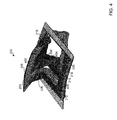
FIGS. 3 and4 depict different isometric views of the example auxiliary power unit inlet apparatus as shown inFIG. 2 in accordance with the teachings of this disclosure. -
FIG. 5 depicts a side view of the example auxiliary power unit inlet apparatus as shown inFIG. 2 in accordance with the teachings of this disclosure. -
FIG. 6 depicts an isometric view of the example auxiliary power unit inlet apparatus as shown inFIG. 2 having an actuator to actuate an example door between an open position and a closed position. - Wherever possible, the same reference numbers will be used throughout the drawing(s) and accompanying written description to refer to the same or like parts.
- The examples disclosed herein relate to air inlet apparatus for vehicles (e.g., airplanes, aircraft, etc.) having two or more air flow paths that prevent and/or minimize adverse effects due to differences in inlet airflows. In some examples, the air inlet apparatus is an auxiliary power unit (APU) inlet apparatus having first and second air flow paths separated by a divider or panel. The first air flow path may be associated with an APU inlet and the second air flow path may be associated with an eductor and/or an APU cooling duct.
- The invention can involve an apparatus that may include an air inlet for an aircraft comprising a first air flow path and a second air flow path, the first air flow path being immediately adjacent the second air flow path, the first air flow path at least partially separated from the second air flow path by a first panel; and a door hingably coupled adjacent the air inlet, the door comprising a second panel extending from an interior surface of the door to substantially prevent air from flowing across the interior surface between the first air flow path and the second air flow path. When the door is in an open position, a portion of the second panel may extend into the air inlet past an edge of the first panel. The first air flow path comprises an auxiliary power unit inlet and the second air flow path comprises an auxiliary power unit cooling duct inlet. The apparatus may also include an actuator to actuate the door between an open position and a closed position. The door may also include opposing side panels extending from the interior surface, the second panel being positioned between the side panels. The second panel may be offset relative the first panel to enable the second panel to be received within one of the first air flow path or the second air flow path when the door is in a closed position. The second panel may be used to substantially prevent a total pressure recovery reduction for the second air flow path when the first air flow path is operating at a higher mass flow rate than the second air flow path.
- The invention may involve a method that may include flowing air into a dual flow auxiliary power unit inlet; and separating the air flow into a first air flow path and a second air flow path using a panel extending from an inlet door. The panel may substantially prevent air from flowing across an interior surface of the inlet door between the first air flow path and the second air flow path. The panel may substantially prevent a total pressure recovery reduction for the second air flow path when the first air flow path is operating at a higher mass flow rate than the second air flow path.
- The invention can involve an apparatus that may include an air inlet for an aircraft comprising a first air flow path and a second air flow path, the first air flow path at least partially separated from the second air flow path by a first panel; a door hingably coupled adjacent the air inlet; and means for substantially preventing a total pressure recovery reduction for the second air flow path when the first air flow path is operating at a higher mass flow rate than the second air flow path. The means for substantially preventing the total pressure recovery reduction may include a second panel extending from an interior surface of the door. The second panel may be offset relative the first panel to enable the second panel to be received within one of the first air flow path or the second air flow path when the door is in a closed position. The means for substantially preventing the total pressure recovery reduction may be to substantially prevent air from flowing across an interior surface of the door between the first air flow path and the second air flow path. The apparatus may also include an actuator to actuate the door between an open position and a closed position. The door may also include opposing side panels extending from an interior surface of the door. The means for substantially preventing the total pressure recovery reduction may be positioned between the side panels.
- To substantially direct fluid flow into the respective air flow paths, the example air inlet apparatus includes an example door or flap that is movably and/or hingably coupled adjacent an inlet aperture of the air inlet apparatus. In some examples, the door includes first and second side flaps and a second divider and/or isolation panel extending from an interior surface of the door and positioned between the first and second side flaps.
- When the aircraft is on the ground, the first and second side flaps substantially prevent corner vortices from forming between lateral edges of the door and an outer skin of the airplane. If such corner vortices form and/or enter the air flow paths, the efficiency of an auxiliary power unit (APU) to which the air inlet apparatus is coupled may be decreased. When the aircraft is airborne, the first and second side flaps substantially prevent air from spilling around the inlet aperture. Thus, the first and second side flaps enable more air to flow into the air flow paths.
- In some examples, the isolation panel, which is positioned between the side flaps, substantially prevents fluid from flowing across the interior surface of the door between the first air flow path and the second air flow path. Thus, one of the air flow paths can operate at a mass flow rate significantly higher than the other without negatively effecting the operation of the lower mass flow rate flow path. Enabling the air flow paths to operate at different mass flow rates without substantial interference enables a total pressure recovery to be increased and/or a flow distortion to be decreased in either and/or both of the lower mass flow rate flow path and/or the higher mass flow rate flow path.
- To enable the door to be stowed and/or retracted and/or to prevent fluid flow into the first and/or second air flow paths, the first and second side flaps and/or the isolation panel may be received within the inlet aperture. In some examples, when the door is in the closed position, the isolation panel is positioned adjacent the first divider and/or the door substantially prevents air from entering the first and/or second flow paths.
-
FIG. 1 illustrates anexample aircraft 100 having an example air inlet apparatus 202 (FIG. 2 ) in accordance with the teachings of this disclosure.FIG. 2 illustrates a more detailed view of theexample aircraft 100 and theapparatus 202. In some examples, theapparatus 202 includes adoor 204 hingably coupled adjacent aninlet aperture 205 of theapparatus 202. In this example, thedoor 204 includes first, second and third inwardly extending fins, dividers, panels and/orflaps inlet aperture 205 and, specifically, first and secondair flow paths door 204 is being shown as having the first andthird dividers door 204 may not include the first andthird dividers apparatus 202 is being shown as having two air flow paths, in other examples, theapparatus 202 may have any number of flow paths (e.g., 3, 4, etc.). In some examples, the first and secondair flow paths flap 216 at least partially positioned within theinlet aperture 205. In some examples, the first and secondair flow paths - In some examples and as shown in
FIGS. 3 and4 , the first andthird dividers flanges interior surface 306 of thedoor 204. In some examples, the first andthird dividers lateral edges door 204 and haveangled surfaces rounded surfaces corners lateral edges inlet aperture 205 when thedoor 204 is in an open position (e.g., shown inFIG. 3 ). WhileFIG. 3 depicts thedoor 204 in a particular open position, thedoor 204 may be positioned at various open positions and/or angles relative to thesurface 324. In some examples, covering thecorners air flow paths corners aircraft 100 is on the ground. Additionally or alternatively, in some examples, the first andthird dividers inlet aperture 205 when theaircraft 100 is in the air. Thus, the first andthird dividers apparatus 202 and theaircraft 100 both on the ground and in the air. - Referring to
FIG. 4 , in some examples, thesecond divider 208 has aflange 402 that is coupled to theinterior surface 306 between the first andthird dividers door 204 to close and thesecond divider 208 to be received within theinlet aperture 205, thesecond divider 208 is off-set relative to the outwardly extendingdivider 216. However, in other examples, thesecond divider 208 can be received within thedivider 216 or thedivider 216 can be received within thesecond divider 208. - In some examples, to enable the first and
second flow paths portion 404 of thesecond divider 208 extends into theinlet aperture 205 past anedge 406 of the outwardly extendingdivider 216, thereby effectively separating thefirst flow path 212 from thesecond flow path 214. More specifically, in this example, thesecond divider 208 enables thefirst flow path 212 to operate at a lower mass flow rate without being negatively affected by thesecond flow path 214 operating at a higher mass flow rate or to enable thesecond flow path 214 to operate at a lower mass flow rate without being negatively affected by thefirst flow path 212 operating at a higher mass flow rate, for example. Enabling the first andsecond flow paths second flow paths - Depending on the status of the aircraft 100 (e.g., on the ground or in the air), the
first flow path 212 or thesecond flow path 214 may have the higher mass flow rate. -
FIG. 5 depicts a side view of theapparatus 202 andFIG. 6 depicts theapparatus 202 having anactuator 602 coupled between thedoor 204 and asurface 604 of theinlet aperture 205. Theactuator 602 is configured to cause thedoor 204 to open or close based on commands received. While an actuator is shown inFIG. 6 , in other examples, the actuator may not be provided. - From the foregoing, it will be appreciated that the above disclosed methods and apparatus substantially reduce air flow across an interior door surface between flow paths (e.g., an APU inlet duct, an APU cooling duct) of a dual flow APU inlet, thereby enabling the flow paths to operate independently. In some examples, the example door includes an integral isolation panel (e.g., the isolation panel is coupled to the door) that extends past an end of an internal divider. Thus, the isolation panel at least partially overlaps the internal divider to effectively divide air streams flowing into the respective air flow paths. In some examples, the isolation panel substantially separates air flowing to different customers (e.g., APU inlet, an eductor and/or an APU cooling duct) to increase the performance of the APU and/or the APU inlet. In some examples, the performance of the APU and/or the APU inlet is increased by substantially preventing an air flow path operating at a higher mass flow rate from negatively effecting an adjacent air flow path operating at a lower mass flow rate. For example, the isolation panel prevents the air flow path operating at the higher mass flow rate from reducing a total pressure recovery and/or increasing flow distortion for the air flow path operating at the lower mass flow rate.
- As set forth herein, an example apparatus includes an air inlet for an aircraft including a first air flow path and a second air flow path. The first air flow path is immediately adjacent the second air flow path. The first air flow path is at least partially separated from the second air flow path by a first panel at least partially positioned within the air inlet. The example apparatus includes a door hingably coupled adjacent the air inlet. The door includes a second panel extending from an interior surface of the door to substantially prevent air from flowing across the interior surface between the first air flow path and the second air flow path.
- In some examples, when the door is in an open position, a portion of the second panel is to extend into the air inlet past an edge of the first panel. In some examples, the first air flow path is an auxiliary power unit inlet and the second air flow path is an auxiliary power unit cooling duct inlet. In some examples, the apparatus also includes an actuator to actuate the door between an open position and a closed position. In some examples, the door also includes opposing side panels extending from the interior surface, the second panel being positioned between the side panels. In some examples, the second panel is offset relative the first panel to enable the second panel to be received within one of the first air flow path or the second air flow path when the door is in a closed position. In some examples, the second panel is to substantially prevent a total pressure recovery reduction for the second air flow path when the first air flow path is operating at a higher mass flow rate than the second air flow path.
- An example method includes flowing air into a dual flow auxiliary power unit inlet and separating the air flow into a first air flow path and a second air flow path using a panel extending from an inlet door. In some examples, the panel substantially prevents air from flowing across an interior surface of the inlet door between the first air flow path and the second air flow path. In some examples, the panel substantially prevents a total pressure recovery reduction for the second air flow path when the first air flow path is operating at a higher mass flow rate than the second air flow path.
- An example apparatus includes an air inlet for an aircraft having a first air flow path and a second air flow path. The first air flow path is at least partially separated from the second air flow path by a first panel at least partially positioned within the air inlet. The apparatus includes a door hingably coupled adjacent the air inlet and means for substantially preventing a total pressure recovery reduction of the second air flow path when the first air flow path is operating at a higher mass flow rate than the second air flow path. In some examples, the means for substantially preventing the total pressure recovery reduction includes a second panel extending from an interior surface of the door. In some examples, the second panel is offset relative the first panel to enable the second panel to be received within one of the first air flow path or the second air flow path when the door is in a closed position.
- In some examples, the means for substantially preventing the total pressure recovery reduction is to substantially prevent air from flowing across an interior surface of the door between the first air flow path and the second air flow path. In some examples, the apparatus also includes an actuator to actuate the door between an open position and a closed position. In some examples, the door further also includes opposing side panels extending from an interior surface of the door. In some examples, the means for substantially preventing the total pressure recovery reduction is to be positioned between the side panels.
- Although certain example methods, apparatus and articles of manufacture have been described herein, the scope of coverage of this patent is not limited thereto. On the contrary, this patent covers all methods, apparatus and articles of manufacture fairly falling within the scope of the claims of this patent.
Claims (10)
- An apparatus, comprising:an air inlet for an aircraft comprising a first air flow path and a second air flow path, the first air flow path being immediately adjacent the second air flow path, the first air flow path at least partially separated from the second air flow path by a first panel; anda door hingably coupled adjacent the air inlet, the door comprising a second panel extending from an interior surface of the door to substantially prevent air from flowing across the interior surface between the first air flow path and the second air flow path.
- The apparatus of claim 1, wherein, when the door is in an open position, a portion of the second panel is to extend into the air inlet past an edge of the first panel.
- The apparatus of claim 1, wherein the first air flow path comprises an auxiliary power unit inlet and the second air flow path comprises an auxiliary power unit cooling duct inlet.
- The apparatus of claim 1, further comprising an actuator to actuate the door between an open position and a closed position.
- The apparatus of claim 1, wherein the door further comprises opposing side panels extending from the interior surface, the second panel being positioned between the side panels.
- The apparatus of claim 1, wherein the second panel is offset relative the first panel to enable the second panel to be received within one of the first air flow path or the second air flow path when the door is in a closed position.
- The apparatus of claim 1, wherein the second panel is to substantially prevent a total pressure recovery reduction for the second air flow path when the first air flow path is operating at a higher mass flow rate than the second air flow path.
- A method, comprising:flowing air into a dual flow auxiliary power unit inlet; andseparating the air flow into a first air flow path and a second air flow path using a panel extending from an inlet door.
- The method of claim 8, wherein the panel substantially prevents air from flowing across an interior surface of the inlet door between the first air flow path and the second air flow path.
- The method of claim 8, wherein the panel substantially prevents a total pressure recovery reduction for the second air flow path when the first air flow path is operating at a higher mass flow rate than the second air flow path.
Applications Claiming Priority (1)
| Application Number | Priority Date | Filing Date | Title |
|---|---|---|---|
| US13/952,219 US9611050B2 (en) | 2013-07-26 | 2013-07-26 | Auxiliary power unit inlet apparatus and methods |
Publications (1)
| Publication Number | Publication Date |
|---|---|
| EP2829475A1 true EP2829475A1 (en) | 2015-01-28 |
Family
ID=50884236
Family Applications (1)
| Application Number | Title | Priority Date | Filing Date |
|---|---|---|---|
| EP20140169918 Ceased EP2829475A1 (en) | 2013-07-26 | 2014-05-26 | Auxiliary power unit inlet apparatus and method |
Country Status (3)
| Country | Link |
|---|---|
| US (2) | US9611050B2 (en) |
| EP (1) | EP2829475A1 (en) |
| CA (1) | CA2854803C (en) |
Cited By (2)
| Publication number | Priority date | Publication date | Assignee | Title |
|---|---|---|---|---|
| CN109774955A (en) * | 2019-03-06 | 2019-05-21 | 成都飞机工业(集团)有限责任公司 | Drag parachute housing structure is buried in one kind is two-door |
| EP3587273A1 (en) * | 2018-06-22 | 2020-01-01 | Airbus Operations, S.L.U. | Air intake system |
Families Citing this family (9)
| Publication number | Priority date | Publication date | Assignee | Title |
|---|---|---|---|---|
| US9611050B2 (en) | 2013-07-26 | 2017-04-04 | The Boeing Company | Auxiliary power unit inlet apparatus and methods |
| US10239632B2 (en) * | 2017-02-20 | 2019-03-26 | Pratt & Whitney Canada Corp. | System and method for controlling an auxiliary power unit inlet door |
| JP6691896B2 (en) * | 2017-08-25 | 2020-05-13 | 三菱重工業株式会社 | aircraft |
| US10989114B2 (en) | 2018-03-07 | 2021-04-27 | The Boeing Company | Systems and methods for cooling bleed air from an aircraft engine |
| FR3080889B1 (en) * | 2018-05-03 | 2020-08-07 | Airbus Operations Sas | AIRCRAFT PROPULSION KIT INCLUDING A COLD AIR INTAKE DEVICE WITH VARIABLE AERODYNAMIC PROFILE |
| US11085372B2 (en) * | 2018-07-18 | 2021-08-10 | The Boeing Company | Anti-ice system exhaust air disruptor |
| US11034463B2 (en) * | 2019-03-26 | 2021-06-15 | The Boeing Company | Aircraft auxiliary power unit (APU) control system having variably sized air inlet |
| US11486306B2 (en) | 2020-06-18 | 2022-11-01 | The Boeing Company | Flush fluid inlet designs for aero-acoustic tone mitigation of aircraft |
| US12275533B2 (en) | 2023-06-02 | 2025-04-15 | Honeywell International Inc. | Inlet system for auxiliary power unit |
Citations (2)
| Publication number | Priority date | Publication date | Assignee | Title |
|---|---|---|---|---|
| US8141818B2 (en) * | 2009-07-02 | 2012-03-27 | Honeywell International Inc. | Ram door assemblies |
| CN102777261A (en) * | 2011-05-13 | 2012-11-14 | 中国商用飞机有限责任公司 | Base plate for air intake damper and air intake damper comprising same |
Family Cites Families (15)
| Publication number | Priority date | Publication date | Assignee | Title |
|---|---|---|---|---|
| US4418879A (en) | 1980-12-29 | 1983-12-06 | The Boeing Company | Scoop and inlet for auxiliary power units and method |
| US5162620A (en) | 1989-11-28 | 1992-11-10 | Allied-Signal Inc. | Dual flow turbine engine muffler |
| US5655359A (en) | 1995-05-15 | 1997-08-12 | The Boeing Company | Passive cooling device and method for cooling an auxiliary power unit on an airplane |
| US6050527A (en) | 1997-12-19 | 2000-04-18 | The Boeing Company | Flow control device to eliminate cavity resonance |
| US6092360A (en) | 1998-07-01 | 2000-07-25 | The Boeing Company | Auxiliary power unit passive cooling system |
| DE19850093C1 (en) | 1998-10-30 | 2000-05-04 | Daimler Chrysler Aerospace | Air intake |
| US6272838B1 (en) | 1999-02-25 | 2001-08-14 | Alliedsignal, Inc. | Method and apparatus for controlling the inlet duct leading to an auxiliary power unit |
| US6264137B1 (en) * | 2000-02-25 | 2001-07-24 | Honeywell International Inc. | Inlet vortex bustor and ice protector for auxiliary power units |
| US6651929B2 (en) | 2001-10-29 | 2003-11-25 | Pratt & Whitney Canada Corp. | Passive cooling system for auxiliary power unit installation |
| US7014144B2 (en) | 2003-07-22 | 2006-03-21 | Honeywell International, Inc. | Dual action inlet door and method for use thereof |
| DE10335482B4 (en) | 2003-08-02 | 2008-04-03 | Airbus Deutschland Gmbh | Raptor air intake of an aircraft |
| US7364116B2 (en) | 2004-09-27 | 2008-04-29 | The Boeing Company | Automatic control systems for aircraft auxiliary power units, and associated methods |
| US7344107B2 (en) | 2004-10-26 | 2008-03-18 | The Boeing Company | Dual flow APU inlet and associated systems and methods |
| ES2401015B1 (en) * | 2011-09-29 | 2014-03-13 | Airbus Operations, S.L. | AIR INTAKE WITH DOUBLE DOOR |
| US9611050B2 (en) | 2013-07-26 | 2017-04-04 | The Boeing Company | Auxiliary power unit inlet apparatus and methods |
-
2013
- 2013-07-26 US US13/952,219 patent/US9611050B2/en active Active
-
2014
- 2014-05-26 EP EP20140169918 patent/EP2829475A1/en not_active Ceased
- 2014-06-19 CA CA2854803A patent/CA2854803C/en active Active
-
2017
- 2017-03-22 US US15/466,521 patent/US10569893B2/en active Active
Patent Citations (2)
| Publication number | Priority date | Publication date | Assignee | Title |
|---|---|---|---|---|
| US8141818B2 (en) * | 2009-07-02 | 2012-03-27 | Honeywell International Inc. | Ram door assemblies |
| CN102777261A (en) * | 2011-05-13 | 2012-11-14 | 中国商用飞机有限责任公司 | Base plate for air intake damper and air intake damper comprising same |
Cited By (4)
| Publication number | Priority date | Publication date | Assignee | Title |
|---|---|---|---|---|
| EP3587273A1 (en) * | 2018-06-22 | 2020-01-01 | Airbus Operations, S.L.U. | Air intake system |
| US11555448B2 (en) | 2018-06-22 | 2023-01-17 | Airbus Operations S.L. | Air intake system |
| CN109774955A (en) * | 2019-03-06 | 2019-05-21 | 成都飞机工业(集团)有限责任公司 | Drag parachute housing structure is buried in one kind is two-door |
| CN109774955B (en) * | 2019-03-06 | 2022-01-25 | 成都飞机工业(集团)有限责任公司 | Double-door embedded resistance umbrella cabin structure |
Also Published As
| Publication number | Publication date |
|---|---|
| US9611050B2 (en) | 2017-04-04 |
| US10569893B2 (en) | 2020-02-25 |
| US20170190439A1 (en) | 2017-07-06 |
| CA2854803C (en) | 2016-09-27 |
| CA2854803A1 (en) | 2015-01-26 |
| US20150031276A1 (en) | 2015-01-29 |
Similar Documents
| Publication | Publication Date | Title |
|---|---|---|
| CA2854803C (en) | Auxiliary power unit inlet apparatus and methods | |
| US7611093B2 (en) | Dual flow APU inlet and associated systems and methods | |
| US8096105B2 (en) | Turbojet engine with attenuated jet noise | |
| RU2494009C2 (en) | Aircraft fresh air intake | |
| US6264137B1 (en) | Inlet vortex bustor and ice protector for auxiliary power units | |
| EP2865599B1 (en) | Auxiliary power unit inlet door having openings formed therein | |
| JP5460952B2 (en) | Air inlet apparatus used in connection with a high speed levitating movable platform and used on a jet aircraft fuselage, aircraft, and method for forming an inlet on an outer surface of a jet aircraft fuselage | |
| US11555448B2 (en) | Air intake system | |
| US10252811B2 (en) | Acoustic controlled ice deflecting auxiliary power unit inlet system | |
| EP3183172B1 (en) | Actuated outlet door for aircraft high-temperature exhaust | |
| EP3069999B1 (en) | Supersonic caret inlet system leading edge slat for improved inlet performance at off-design flight conditions | |
| EP3472044B1 (en) | Panels for obstructing air flow through apertures in an aircraft wing | |
| EP2272758B1 (en) | Ram door assemblies | |
| US9145801B2 (en) | Systems and methods for acoustic resonance mitigation | |
| CA2914133A1 (en) | Aircraft wing rib | |
| EP2987988B1 (en) | Low noise aeroengine inlet system | |
| US10532805B2 (en) | Airfoil for an aircraft having reduced noise generation | |
| JP2011519782A (en) | Aircraft fillet fairing with fixed and moving parts, and related systems and methods | |
| EP2574553A1 (en) | Aircraft outflow valve | |
| US20160280388A1 (en) | Intake structure of aircraft | |
| US20150344158A1 (en) | Space aircraft | |
| US20200247541A1 (en) | Aircraft pylon |
Legal Events
| Date | Code | Title | Description |
|---|---|---|---|
| 17P | Request for examination filed |
Effective date: 20140526 |
|
| AK | Designated contracting states |
Kind code of ref document: A1 Designated state(s): AL AT BE BG CH CY CZ DE DK EE ES FI FR GB GR HR HU IE IS IT LI LT LU LV MC MK MT NL NO PL PT RO RS SE SI SK SM TR |
|
| AX | Request for extension of the european patent |
Extension state: BA ME |
|
| PUAI | Public reference made under article 153(3) epc to a published international application that has entered the european phase |
Free format text: ORIGINAL CODE: 0009012 |
|
| R17P | Request for examination filed (corrected) |
Effective date: 20150401 |
|
| RBV | Designated contracting states (corrected) |
Designated state(s): AL AT BE BG CH CY CZ DE DK EE ES FI FR GB GR HR HU IE IS IT LI LT LU LV MC MK MT NL NO PL PT RO RS SE SI SK SM TR |
|
| 17Q | First examination report despatched |
Effective date: 20150811 |
|
| STAA | Information on the status of an ep patent application or granted ep patent |
Free format text: STATUS: THE APPLICATION HAS BEEN REFUSED |
|
| 18R | Application refused |
Effective date: 20161114 |