EP2829474A1 - Monitoring system for monitoring a two-part-cowl lock unit - Google Patents
Monitoring system for monitoring a two-part-cowl lock unit Download PDFInfo
- Publication number
- EP2829474A1 EP2829474A1 EP20130382294 EP13382294A EP2829474A1 EP 2829474 A1 EP2829474 A1 EP 2829474A1 EP 20130382294 EP20130382294 EP 20130382294 EP 13382294 A EP13382294 A EP 13382294A EP 2829474 A1 EP2829474 A1 EP 2829474A1
- Authority
- EP
- European Patent Office
- Prior art keywords
- rod
- lock unit
- state
- main
- monitoring
- Prior art date
- Legal status (The legal status is an assumption and is not a legal conclusion. Google has not performed a legal analysis and makes no representation as to the accuracy of the status listed.)
- Granted
Links
- 238000012544 monitoring process Methods 0.000 title claims abstract description 45
- 230000000284 resting effect Effects 0.000 claims description 4
- 230000000717 retained effect Effects 0.000 description 2
- 230000003213 activating effect Effects 0.000 description 1
- 230000008878 coupling Effects 0.000 description 1
- 238000010168 coupling process Methods 0.000 description 1
- 238000005859 coupling reaction Methods 0.000 description 1
- 230000001419 dependent effect Effects 0.000 description 1
- 238000012423 maintenance Methods 0.000 description 1
- 238000000034 method Methods 0.000 description 1
- 230000000007 visual effect Effects 0.000 description 1
Images

Classifications
-
- E—FIXED CONSTRUCTIONS
- E05—LOCKS; KEYS; WINDOW OR DOOR FITTINGS; SAFES
- E05B—LOCKS; ACCESSORIES THEREFOR; HANDCUFFS
- E05B81/00—Power-actuated vehicle locks
- E05B81/54—Electrical circuits
- E05B81/64—Monitoring or sensing, e.g. by using switches or sensors
- E05B81/72—Monitoring or sensing, e.g. by using switches or sensors the lock status, i.e. locked or unlocked condition
-
- B—PERFORMING OPERATIONS; TRANSPORTING
- B64—AIRCRAFT; AVIATION; COSMONAUTICS
- B64D—EQUIPMENT FOR FITTING IN OR TO AIRCRAFT; FLIGHT SUITS; PARACHUTES; ARRANGEMENTS OR MOUNTING OF POWER PLANTS OR PROPULSION TRANSMISSIONS IN AIRCRAFT
- B64D29/00—Power-plant nacelles, fairings, or cowlings
- B64D29/06—Attaching of nacelles, fairings or cowlings
-
- E—FIXED CONSTRUCTIONS
- E05—LOCKS; KEYS; WINDOW OR DOOR FITTINGS; SAFES
- E05B—LOCKS; ACCESSORIES THEREFOR; HANDCUFFS
- E05B41/00—Locks with visible indication as to whether the lock is locked or unlocked
-
- E—FIXED CONSTRUCTIONS
- E05—LOCKS; KEYS; WINDOW OR DOOR FITTINGS; SAFES
- E05C—BOLTS OR FASTENING DEVICES FOR WINGS, SPECIALLY FOR DOORS OR WINDOWS
- E05C1/00—Fastening devices with bolts moving rectilinearly
- E05C1/08—Fastening devices with bolts moving rectilinearly with latching action
-
- E—FIXED CONSTRUCTIONS
- E05—LOCKS; KEYS; WINDOW OR DOOR FITTINGS; SAFES
- E05B—LOCKS; ACCESSORIES THEREFOR; HANDCUFFS
- E05B81/00—Power-actuated vehicle locks
- E05B81/54—Electrical circuits
- E05B81/64—Monitoring or sensing, e.g. by using switches or sensors
-
- Y—GENERAL TAGGING OF NEW TECHNOLOGICAL DEVELOPMENTS; GENERAL TAGGING OF CROSS-SECTIONAL TECHNOLOGIES SPANNING OVER SEVERAL SECTIONS OF THE IPC; TECHNICAL SUBJECTS COVERED BY FORMER USPC CROSS-REFERENCE ART COLLECTIONS [XRACs] AND DIGESTS
- Y10—TECHNICAL SUBJECTS COVERED BY FORMER USPC
- Y10S—TECHNICAL SUBJECTS COVERED BY FORMER USPC CROSS-REFERENCE ART COLLECTIONS [XRACs] AND DIGESTS
- Y10S292/00—Closure fasteners
- Y10S292/49—Toggle catches
-
- Y—GENERAL TAGGING OF NEW TECHNOLOGICAL DEVELOPMENTS; GENERAL TAGGING OF CROSS-SECTIONAL TECHNOLOGIES SPANNING OVER SEVERAL SECTIONS OF THE IPC; TECHNICAL SUBJECTS COVERED BY FORMER USPC CROSS-REFERENCE ART COLLECTIONS [XRACs] AND DIGESTS
- Y10—TECHNICAL SUBJECTS COVERED BY FORMER USPC
- Y10T—TECHNICAL SUBJECTS COVERED BY FORMER US CLASSIFICATION
- Y10T292/00—Closure fasteners
- Y10T292/08—Bolts
- Y10T292/096—Sliding
Definitions
- the present invention belongs to the field of aircraft structures and, more particularly, to the field of elements monitoring the correct lock unit of a cowl comprised in an aircraft.
- Document US 4,613,099 shows a device mounted inside an engine cowling structure and providing a signal indicating when an internal latch is left inadvertenly unlatched when the cowlings are closed. Further, the signal prevents adjacent cowlings from closing until the internal latch is properly secured.
- Document GB 2 170 548 A discloses a safety lock of a latch element with an indicator system that closure has occurred correctly. Correct or incorrect position of the latch causes the indicator to move in a guide, so that when the closure has occurred properly, the latch moves to the indicator from a position corresponding to a circle of small diameter at a position corresponding to a circle of greater diameter.
- the present invention discloses an alternative system for secure closure of said cowls, providing a warning system for the case in which said closure has not occurred safely.
- the present invention provides an alternative solution for the aforementioned problems, by a system for monitoring a two-part-cowl lock unit according to claim 1 and an aircraft according to claim 8.
- preferred embodiments of the invention are defined.
- the invention provides a system for monitoring the state of a two-part-cowl lock unit, the lock unit comprising a pair hook-keeper, the system comprising:
- the rod is mechanically connected to the keeper of the lock unit.
- the first position of the rod is that in which the keeper is not engaged with the hook
- the second position of the rod is that in which the keeper is engaged with the hook
- the warning means comprise a proximity sensor and the rod comprises a proximity device recognizable by the proximity sensor.
- the warning means comprise a cable mechanically coupled with the rod in a way that one position of the rod corresponds to a rest state of the cable and the other position of the rod corresponds to a pulled state of the cable.
- the cable is connected to a flap, the rest state of the cable corresponding to a closed state of the flap and the pulled state of the cable corresponding to an open state of the flap.
- the system further comprises a tilting piece with a first portion at one side of the tilting axis and a second portion at the other side of the tilting axis of the tilting piece, wherein the rod is mechanically connected to one portion of the tilting piece and the cable is connected to the other portion of the tilting piece.
- the invention provides a system for monitoring the state of a two-part-cowl lock, the lock comprising a plurality of lock units, each lock unit comprising a pair hook-keeper, the system comprising
- the warning means comprise first warning means comprising a proximity sensor for each lock unit and each rod comprising a target recognizable by the proximity sensor.
- the cowl lock comprise one main lock unit and at least one normal lock unit, wherein the warning means comprise second warning means, the system comprising:
- any of these first and second warning means comprised in the systems described in the first and second inventive aspects are suitable for being placed in any part of the aircraft, in particular where they can be easily visible by the person in charge of monitoring the correct locking of the locks.
- the invention provides an aircraft comprising a system for monitoring the state of a two-part-cowl lock unit according to the first inventive aspect and/or a system for monitoring the state of a two-part-cowl lock according to the second inventive aspect.
- the first state is an outward state, because the rod (11) is out further from the cowl lock unit (2) and the second state is an inward state, because the rod (11) is nearer the cowl lock unit (2).
- each lock unit (2) comprises a pair hook (3)-keeper (4), and the rod (11) is mechanically coupled to the keeper (4) of the lock unit (2).
- the monitoring system (1) comprises first warning means (5), which are adapted to be activated by the rod (11) when it moves to an outward position.
- These first warning means (5) comprise a structure (6) which contains a proximity sensor (7) and a target (8) which can be detectable by the proximity sensor (7) and is arranged on the rod (11).
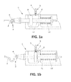
- Figure 1a shows the monitoring system (1) when the lock unit (2) is closed.
- the rod (11) is engaged and cannot be moved and the spring (12), which is arranged in connection with the rod (11), tries to expand, but as the rod (11) is engaged, it is not dragged by the spring (12), thus remaining in an inward position.
- the proximity sensor (7) is not activated, because the target (8) is far enough to not be detected by the proximity sensor (7).
- Figure 1b shows the system when the lock unit (2) is open.
- the rod (11) is loose, and is carried by the spring (12) to an outward position, while the spring (12) extends.
- the target (8) is thus carried by the rod (11) towards near the proximity sensor (7), thus activating it, so that the first warning means (5) issue an electronic warning of "open lock".
- the target (8) is arranged so that when the rod (11) is in its inward position, the target (8) activates the proximity sensor (7), and when the rod (11) is in its outward position, the target (8) is far enough to be detected by the proximity sensor (7).
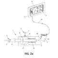
- FIGS 2a and 2b show another particular embodiment of the monitoring system (1) according to the invention.
- the rod (11) is mechanically coupled to the keeper (4) of the lock unit (2), and the spring (12) is arranged as in the embodiment shown in Figures 1a and 1b .
- This embodiment also comprises first warning means (5).
- the monitoring system (1) also comprises second warning means (9).
- These second warning means (9) comprise a cable (10) mechanically coupled with the rod (11), a tilting piece (13), a secondary spring (14), secondary locking means (15), a flap (16) and a torsion spring (17).
- the cable (10) is coupled with the rod (11) by means of the tilting piece (13).
- the tilting piece (13) is a rigid piece with two portions.
- First portion is at reach of the rod (11), in a way that when the rod (11) is in its outward state, the rod (11) pushes the first portion of the tilting piece (13), and the movement of this portion is transmitted to the second portion, which is in turn attached to the cable (10).
- This tilting piece (13) is provided with the secondary spring (14) that set the tilting piece (13) at a resting position against a stop (18) when no force is exerted to the tilting piece (13).
- Figure 2a shows the monitoring system (1) when the lock unit (2) is closed, causing the rod (11) being in its inward position and the spring (12) being in the compressed position, as explained in Figure 1a .
- the rod (11) does not press the first portion of the tilting piece (13), so the second portion of the tilting piece (13) does not exert any force to the cable (10), the cable remaining at its rest position.
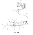
- Figure 2b shows the system when the lock unit (2) is open, and the rod (11) is therefore in its outward position, as explained in Figure 1b .
- the rod (11) pushes the first portion of the tilting piece (13), causing its tilting, so that the second portion of the tilting piece (13) pulls of the cable (10).
- the cable (10) is connected to the secondary locking means (15) adapted to hold and release the flap (16).
- Figure 2a shows the cable (10) at its rest position.
- the cable (10) is inside the secondary locking means (15) and this fact causes the secondary locking means (15) to be closed, and therefore, the flap (16) is retained.
- this system (1) prevents the flap (16) from remaining closed if a third party tries to close it when the lock unit (2) is not properly closed.
- the secondary locking means (15) are always connected to the cable (10) and the cable (10) remains pulled until the lock unit (2) is properly closed, the secondary locking means (15) do not retain the flap (16) in its closed position, the flap (16) being therefore moved by the torsion spring (17) to stand out.
- the system (1) comprises this second warning means (9), but without the first warning means (5).
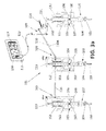
- FIGS 3a and 3b show an embodiment of a complex monitoring system (101) according to the invention.
- This complex monitoring system (101) is suitable for monitoring a cowl lock with several lock units (102, 120), each of one comprising a pair hook (103)-keeper (104).
- the cowl lock comprises one main lock unit (120) and at least one normal lock unit (102).
- this complex monitoring system (101) allows the monitoring of a cowl lock that requires that a warning is issued when any of them are not closed correctly.
- This complex monitoring system (101) comprises:
- the complex monitoring system (101) also comprises warning means (105, 109) adapted to be activated by any of the rods (111).
- each rod (111) is mechanically coupled to a keeper (104) of the lock unit (102, 120) so that if a lock unit (102, 120) is closed, its rod (111) is engaged and cannot be moved.
- a spring (112) is arranged in connection with each rod (111), so that when a spring (112) extends, it tries to drag its rod (111) therewith. If a lock unit (102, 120) is open, its rod (111) is loose, and can be carried by its spring (112) to an outward position. If a lock unit (102, 120) is closed, as its rod (111) is attached thereto, its spring (112) cannot move the rod (111), and the rod (111) remains in an inward position.
- the complex monitoring system (101) comprises first warning means (105), comprising a structure (106) which contains one proximity sensor (107) for each lock unit and a target (108) which can be detectable by the proximity sensor (107), arranged on each rod (111), so that when a rod (111) is in its inward position, it activates its proximity sensor (107), and the first warning means (105) interprets that this lock unit (102, 120) is closed.
- first warning means comprising a structure (106) which contains one proximity sensor (107) for each lock unit and a target (108) which can be detectable by the proximity sensor (107), arranged on each rod (111), so that when a rod (111) is in its inward position, it activates its proximity sensor (107), and the first warning means (105) interprets that this lock unit (102, 120) is closed.
- the target (108) is far to activate its proximity sensor (107), and the first warning means (105) issue an electronic warning of "open lock”.
- the target (108) is arranged so that when the rod (111) is in its outward position, the target (108) activates the proximity sensor (107), and when the rod (111) is in its inward position, the target (108) is far enough to be detected by the proximity sensor (107).
- First warning means (105) are suitable for being programmed to interpret both situations. In a particular embodiment, these first warning means (105) are programmable, so that the user is able to choose if the warning is issued when any of the lock units (102, 120) are not properly closed, or if a determined lock unit (102, 120) is not properly closed or if at least a number of them are not properly closed.
- the complex monitoring system (101) comprises also second coupled warning means (109).
- the operation of these second coupled warning means (109) is based on the operation of second warning means (9) used in the first embodiment with a single lock unit (2).
- the second coupled warning means (109) uses one rod (111) mechanically coupled to each keeper (104) of each lock unit (102, 120) comprised in the lock, these rods (111) being the same as the ones which are used in the first warning means (105).
- These second coupled warning means (109) also comprise one tilting piece (113) for each normal lock unit (102), and a main tilting piece (121) for the main lock unit (120).
- These second coupled warning means (109) comprise one transmitting rod (110) for each normal lock unit (102), and one main cable (122) for the main lock unit (120).
- Each transmitting rod (110) connect the tilting piece (113) of one lock unit to the tilting piece (113) of the next lock unit.
- This main tilting piece (121) is provided with a main spring (114) that set the main tilting piece (121) at a resting position against a stop (118) when no force is exerted to the main tilting piece (121).
- the main cable (122) connects the main tilting piece (121) of the main lock unit (120) with the main locking means (115), which are adapted to hold and release a flap (116).
- the main tilting piece (121) therefore comprises at least three portions. First portion is attached to the main transmitting rod (110A), that is also connected to the normal lock unit (102) which is next to the main lock unit (120). Second portion is in reach of the rod (111) which is connected to the main lock unit (120) and third portion is connected to the main cable (122). In this way, when neither the main transmitting rod (110A) nor the rod (111) of the main lock unit (120) acts over the main tilting piece (121), it remains at its rest position because of the main spring (114) that set the main tilting piece (121) against the stop (118). When either the main transmitting rod (110A) or the rod (111) of the main lock unit (120) acts over the main tilting piece (121), the main tilting piece (121) transmits the movement to the main cable (122), pulling it.
- Figure 3a shows a complex monitoring system (101) according to the invention when all the lock units (102, 120) are closed and, because of that, all the rods (111) are in its inward position, and the springs (112) are compressed, so no first warning means (105) are activated.
- the rods (111) are in its inward position and the springs (112) are thus in the compressed position, no rod (111) presses any tilting piece (113), no tilting piece (113) does exert any force to any transmitting rod (110), and as the rod (111) of the main lock unit (120) does not acts over the main tilting piece (121) either, the main cable (122) remaining at its rest position.
- Figure 3b shows the same monitoring system (101) of figure 3a , but when one of the lock units (102, 120) is open.
- This open lock unit can be either a normal lock unit (102) or the main lock unit (120). In the embodiment of this figure, it is the central lock unit which is open.
- one lock unit (102) is open, its rod (111) is loose, so its spring (112) extends and drags the rod (111) with it, causing its target (108) to be far from the proximity sensor (107), causing the first warning means (105) to activate.
- the rod (111) As the rod (111) is therefore in its outward position, it pushes one portion of the tilting piece (113), causing its tilting, so that the other portion of the tilting piece (113) pulls the transmitting rod (110) of the open lock unit, which in this case coincides with the main transmitting rod (110A).
- the movement is transmitted from transmitting rod to transmitting rod until reaching the main transmitting rod (110A), which pulls the main tilting piece (121).
- the main tilting piece (121) pulls the main cable (122).
- the main cable (122) gets out the main locking means (115), causing the flap (116) to be released and, after being moved by a torsion spring (117), to stand out, becoming the mechanic warning of "open lock".
- this monitoring system (101) prevents the flap (116) from remaining closed if a third party tries to close it when the lock unit (102, 120) is not properly closed.
- the main locking means (115) are always connected to the main cable (122) and the main cable (122) remains pulled until the lock unit (102, 120) is properly closed, the main locking means (115) do not retain the flap (116) in its closed position, the flap (116) being therefore moved by the torsion spring (117) to stand out.
Abstract
Description
- The present invention belongs to the field of aircraft structures and, more particularly, to the field of elements monitoring the correct lock unit of a cowl comprised in an aircraft.
- In ordinary maintenance of an aircraft, there are some operations whose failure could pose some problems when operating said aircraft. One is the closure of the cowls that cover each of the engines of the aircraft.
- Document
US 4,613,099 shows a device mounted inside an engine cowling structure and providing a signal indicating when an internal latch is left inadvertenly unlatched when the cowlings are closed. Further, the signal prevents adjacent cowlings from closing until the internal latch is properly secured. - Document
US 5,518,206 shows a visual warning based on the projection of an element which is released when the closure parts move to a predetermined open position. The warning is not however easily seen, as it must be placed in the joint line of both fan cowls. -
Document GB 2 170 548 A - These inventions provide different ways of warning the incorrect locking of a latch-hook system. However, if the engine is mounted beneath the aircraft wing, the cowling locking mechanism located beneath the engine in a position which is very close to the ground being therefore awkward to access.
- The present invention discloses an alternative system for secure closure of said cowls, providing a warning system for the case in which said closure has not occurred safely.
- The present invention provides an alternative solution for the aforementioned problems, by a system for monitoring a two-part-cowl lock unit according to
claim 1 and an aircraft according toclaim 8. In dependent claims, preferred embodiments of the invention are defined. - In a first inventive aspect, the invention provides a system for monitoring the state of a two-part-cowl lock unit, the lock unit comprising a pair hook-keeper, the system comprising:
- a rod mechanically connected to the lock unit,
- a spring mechanically coupled with the rod in a way that an extended state of the spring corresponds to a first position of the rod, and a compressed state of the spring corresponds to a second position of the rod, and
- warning means adapted to be activated by the rod, and to warn of the state of the two-part-cowl lock unit.
- In a particular embodiment, the rod is mechanically connected to the keeper of the lock unit.
- In a particular embodiment, the first position of the rod is that in which the keeper is not engaged with the hook, and the second position of the rod is that in which the keeper is engaged with the hook.
- In a particular embodiment, the warning means comprise a proximity sensor and the rod comprises a proximity device recognizable by the proximity sensor.
- In a particular embodiment, the warning means comprise a cable mechanically coupled with the rod in a way that one position of the rod corresponds to a rest state of the cable and the other position of the rod corresponds to a pulled state of the cable.
- In a particular embodiment, the cable is connected to a flap, the rest state of the cable corresponding to a closed state of the flap and the pulled state of the cable corresponding to an open state of the flap.
- In a particular embodiment, the system further comprises a tilting piece with a first portion at one side of the tilting axis and a second portion at the other side of the tilting axis of the tilting piece, wherein the rod is mechanically connected to one portion of the tilting piece and the cable is connected to the other portion of the tilting piece.
- In a second inventive aspect, the invention provides a system for monitoring the state of a two-part-cowl lock, the lock comprising a plurality of lock units, each lock unit comprising a pair hook-keeper, the system comprising
- one rod for each pair hook-keeper, each rod being mechanically connected to each pair hook-keeper,
- one spring for each pair hook-keeper, each spring mechanically coupled with its rod in a way that an extended state of the spring corresponds to a first position of the rod, and a compressed state of the spring corresponds to a second position of the rod, and
- warning means adapted to be activated by any of the rods and to warn of the state of two-part-cowl lock units.
- In a particular embodiment, the warning means comprise first warning means comprising a proximity sensor for each lock unit and each rod comprising a target recognizable by the proximity sensor.
- In a particular embodiment, the cowl lock comprise one main lock unit and at least one normal lock unit, wherein the warning means comprise second warning means, the system comprising:
- one tilting piece for each lock unit, and a main tilting piece for the main lock unit,
- one transmitting rod for each lock unit, and one main cable for the main lock unit, each transmitting rod connecting the tilting piece of one lock unit to the tilting piece of the next lock unit,
- a main spring that sets the main tilting piece at a resting position against a stop when no force is exerted to the main tilting piece,
- Advantageously, any of these first and second warning means comprised in the systems described in the first and second inventive aspects are suitable for being placed in any part of the aircraft, in particular where they can be easily visible by the person in charge of monitoring the correct locking of the locks.
- In a third inventive aspect, the invention provides an aircraft comprising a system for monitoring the state of a two-part-cowl lock unit according to the first inventive aspect and/or a system for monitoring the state of a two-part-cowl lock according to the second inventive aspect.
- All the features described in this specification (including the claims, description and drawings) and/or all the steps of the described method can be combined in any combination, with the exception of combinations of such mutually exclusive features and/or steps.
- These and other characteristics and advantages of the invention will become clearly understood in view of the detailed description of the invention which becomes apparent from a preferred embodiment of the invention, given just as an example and not being limited thereto, with reference to the drawings.
-
Figures 1a and 1b These figures show a particular embodiment of a monitoring system according to the invention, with first electronic warning means in its two positions. -
Figures 2a and2b These figures show a particular embodiment of a monitoring system according to the invention, with second mechanical warning means in its two positions. -
Figure 3 This figure shows a particular embodiment of a complex monitoring system according to the invention. -
-
Figures 1a and 1b shows a particular monitoring system (1) for monitoring a two-part-cowl lock unit (2) according to the invention. The system comprises:- a rod (11) which is mechanically connected to the lock unit (2), and
- a spring (12) mechanically coupled with the rod (11) in a way that an extended state of the spring (12) corresponds to an first state of the rod (11), and a compressed state of the spring (12) corresponds to an second state of the rod (11).
- In the embodiments shown in this description, the first state is an outward state, because the rod (11) is out further from the cowl lock unit (2) and the second state is an inward state, because the rod (11) is nearer the cowl lock unit (2).
- In the particular embodiment of these
Figures 1a and 1b , each lock unit (2) comprises a pair hook (3)-keeper (4), and the rod (11) is mechanically coupled to the keeper (4) of the lock unit (2). - In this embodiment of
Figures 1a and 1b , the monitoring system (1) comprises first warning means (5), which are adapted to be activated by the rod (11) when it moves to an outward position. These first warning means (5) comprise a structure (6) which contains a proximity sensor (7) and a target (8) which can be detectable by the proximity sensor (7) and is arranged on the rod (11). -
Figure 1a shows the monitoring system (1) when the lock unit (2) is closed. The rod (11) is engaged and cannot be moved and the spring (12), which is arranged in connection with the rod (11), tries to expand, but as the rod (11) is engaged, it is not dragged by the spring (12), thus remaining in an inward position. In this case, the proximity sensor (7) is not activated, because the target (8) is far enough to not be detected by the proximity sensor (7). -
Figure 1b shows the system when the lock unit (2) is open. In this case, the rod (11) is loose, and is carried by the spring (12) to an outward position, while the spring (12) extends. The target (8) is thus carried by the rod (11) towards near the proximity sensor (7), thus activating it, so that the first warning means (5) issue an electronic warning of "open lock". - In another embodiment, the target (8) is arranged so that when the rod (11) is in its inward position, the target (8) activates the proximity sensor (7), and when the rod (11) is in its outward position, the target (8) is far enough to be detected by the proximity sensor (7).
-
Figures 2a and2b show another particular embodiment of the monitoring system (1) according to the invention. The rod (11) is mechanically coupled to the keeper (4) of the lock unit (2), and the spring (12) is arranged as in the embodiment shown inFigures 1a and 1b . This embodiment also comprises first warning means (5). In this particular embodiment, the monitoring system (1) also comprises second warning means (9). These second warning means (9) comprise a cable (10) mechanically coupled with the rod (11), a tilting piece (13), a secondary spring (14), secondary locking means (15), a flap (16) and a torsion spring (17). The cable (10) is coupled with the rod (11) by means of the tilting piece (13). The tilting piece (13) is a rigid piece with two portions. It is attached to a fixed point so that the movement of one portion is transmitted to the other portion. First portion is at reach of the rod (11), in a way that when the rod (11) is in its outward state, the rod (11) pushes the first portion of the tilting piece (13), and the movement of this portion is transmitted to the second portion, which is in turn attached to the cable (10). This is how the coupling between the rod (11) and the cable (10) is achieved. This tilting piece (13) is provided with the secondary spring (14) that set the tilting piece (13) at a resting position against a stop (18) when no force is exerted to the tilting piece (13). -
Figure 2a shows the monitoring system (1) when the lock unit (2) is closed, causing the rod (11) being in its inward position and the spring (12) being in the compressed position, as explained inFigure 1a . In this case, the rod (11) does not press the first portion of the tilting piece (13), so the second portion of the tilting piece (13) does not exert any force to the cable (10), the cable remaining at its rest position.Figure 2b shows the system when the lock unit (2) is open, and the rod (11) is therefore in its outward position, as explained inFigure 1b . In this case, the rod (11) pushes the first portion of the tilting piece (13), causing its tilting, so that the second portion of the tilting piece (13) pulls of the cable (10). - In this embodiment, as shown in the
Figures 2a and2b , the cable (10) is connected to the secondary locking means (15) adapted to hold and release the flap (16). -
Figure 2a shows the cable (10) at its rest position. The cable (10) is inside the secondary locking means (15) and this fact causes the secondary locking means (15) to be closed, and therefore, the flap (16) is retained. - In
Figure 2b , when the cable (10) is pulled, the cable (10) gets out the secondary locking means (15), causing the flap (16) to be released and, after being moved by the torsion spring (17), to stand out, becoming the mechanic warning of "open lock". In a particular embodiment, the torsion spring (17) is a spring loaded hinge. - Advantageously, this system (1) prevents the flap (16) from remaining closed if a third party tries to close it when the lock unit (2) is not properly closed. As the secondary locking means (15) are always connected to the cable (10) and the cable (10) remains pulled until the lock unit (2) is properly closed, the secondary locking means (15) do not retain the flap (16) in its closed position, the flap (16) being therefore moved by the torsion spring (17) to stand out.
- In a particular embodiment, not shown in these figures, the system (1) comprises this second warning means (9), but without the first warning means (5).
-
Figures 3a and3b show an embodiment of a complex monitoring system (101) according to the invention. This complex monitoring system (101) is suitable for monitoring a cowl lock with several lock units (102, 120), each of one comprising a pair hook (103)-keeper (104). The cowl lock comprises one main lock unit (120) and at least one normal lock unit (102). Advantageously, this complex monitoring system (101) allows the monitoring of a cowl lock that requires that a warning is issued when any of them are not closed correctly. This complex monitoring system (101) comprises: - one rod (111) for each normal lock unit (102), and one rod (111) for the main lock unit (120), each rod (111) being mechanically connected to its lock unit (102, 120), and
- one spring (112) for each rod (111), each spring (112) mechanically coupled with its rod (111) in the same way as it was in the embodiment shown in
Figures 1 and2 . - The complex monitoring system (101) also comprises warning means (105, 109) adapted to be activated by any of the rods (111).
- In a particular embodiment, each rod (111) is mechanically coupled to a keeper (104) of the lock unit (102, 120) so that if a lock unit (102, 120) is closed, its rod (111) is engaged and cannot be moved. A spring (112) is arranged in connection with each rod (111), so that when a spring (112) extends, it tries to drag its rod (111) therewith. If a lock unit (102, 120) is open, its rod (111) is loose, and can be carried by its spring (112) to an outward position. If a lock unit (102, 120) is closed, as its rod (111) is attached thereto, its spring (112) cannot move the rod (111), and the rod (111) remains in an inward position.
- In the embodiment shown in
Figure 3a and3b , the complex monitoring system (101) comprises first warning means (105), comprising a structure (106) which contains one proximity sensor (107) for each lock unit and a target (108) which can be detectable by the proximity sensor (107), arranged on each rod (111), so that when a rod (111) is in its inward position, it activates its proximity sensor (107), and the first warning means (105) interprets that this lock unit (102, 120) is closed. When a rod (111) is in its outward position, the target (108) is far to activate its proximity sensor (107), and the first warning means (105) issue an electronic warning of "open lock". In another embodiment, the target (108) is arranged so that when the rod (111) is in its outward position, the target (108) activates the proximity sensor (107), and when the rod (111) is in its inward position, the target (108) is far enough to be detected by the proximity sensor (107). First warning means (105) are suitable for being programmed to interpret both situations. In a particular embodiment, these first warning means (105) are programmable, so that the user is able to choose if the warning is issued when any of the lock units (102, 120) are not properly closed, or if a determined lock unit (102, 120) is not properly closed or if at least a number of them are not properly closed. - In this embodiment shown in
Figure 3a and3b , the complex monitoring system (101) comprises also second coupled warning means (109). The operation of these second coupled warning means (109) is based on the operation of second warning means (9) used in the first embodiment with a single lock unit (2). - As in the case of the first embodiment with a single lock unit (2), the second coupled warning means (109) uses one rod (111) mechanically coupled to each keeper (104) of each lock unit (102, 120) comprised in the lock, these rods (111) being the same as the ones which are used in the first warning means (105).
- These second coupled warning means (109) also comprise one tilting piece (113) for each normal lock unit (102), and a main tilting piece (121) for the main lock unit (120).
- These second coupled warning means (109) comprise one transmitting rod (110) for each normal lock unit (102), and one main cable (122) for the main lock unit (120). Each transmitting rod (110) connect the tilting piece (113) of one lock unit to the tilting piece (113) of the next lock unit. Among them, there is one main transmitting rod (110A) that connects the tilting piece (113) of the normal lock unit (102) which is next to the main lock unit (120) to the main tilting piece (121) of the main lock unit (120). This main tilting piece (121) is provided with a main spring (114) that set the main tilting piece (121) at a resting position against a stop (118) when no force is exerted to the main tilting piece (121). The main cable (122) connects the main tilting piece (121) of the main lock unit (120) with the main locking means (115), which are adapted to hold and release a flap (116).
- The main tilting piece (121) therefore comprises at least three portions. First portion is attached to the main transmitting rod (110A), that is also connected to the normal lock unit (102) which is next to the main lock unit (120). Second portion is in reach of the rod (111) which is connected to the main lock unit (120) and third portion is connected to the main cable (122). In this way, when neither the main transmitting rod (110A) nor the rod (111) of the main lock unit (120) acts over the main tilting piece (121), it remains at its rest position because of the main spring (114) that set the main tilting piece (121) against the stop (118). When either the main transmitting rod (110A) or the rod (111) of the main lock unit (120) acts over the main tilting piece (121), the main tilting piece (121) transmits the movement to the main cable (122), pulling it.
- As in the first embodiment with a single lock unit (2), if nothing acts over the main cable (122), it is inside the main locking means (115), and this fact causes the main locking means (115) to be closed, and therefore, the flap (116) is retained.
-
Figure 3a shows a complex monitoring system (101) according to the invention when all the lock units (102, 120) are closed and, because of that, all the rods (111) are in its inward position, and the springs (112) are compressed, so no first warning means (105) are activated. As the rods (111) are in its inward position and the springs (112) are thus in the compressed position, no rod (111) presses any tilting piece (113), no tilting piece (113) does exert any force to any transmitting rod (110), and as the rod (111) of the main lock unit (120) does not acts over the main tilting piece (121) either, the main cable (122) remaining at its rest position.Figure 3b shows the same monitoring system (101) offigure 3a , but when one of the lock units (102, 120) is open. This open lock unit can be either a normal lock unit (102) or the main lock unit (120). In the embodiment of this figure, it is the central lock unit which is open. When one lock unit (102) is open, its rod (111) is loose, so its spring (112) extends and drags the rod (111) with it, causing its target (108) to be far from the proximity sensor (107), causing the first warning means (105) to activate. As the rod (111) is therefore in its outward position, it pushes one portion of the tilting piece (113), causing its tilting, so that the other portion of the tilting piece (113) pulls the transmitting rod (110) of the open lock unit, which in this case coincides with the main transmitting rod (110A). The movement is transmitted from transmitting rod to transmitting rod until reaching the main transmitting rod (110A), which pulls the main tilting piece (121). The main tilting piece (121) pulls the main cable (122). The main cable (122) gets out the main locking means (115), causing the flap (116) to be released and, after being moved by a torsion spring (117), to stand out, becoming the mechanic warning of "open lock". - Advantageously, as in the embodiment shown in
figures 2a and2b , this monitoring system (101) prevents the flap (116) from remaining closed if a third party tries to close it when the lock unit (102, 120) is not properly closed. As the main locking means (115) are always connected to the main cable (122) and the main cable (122) remains pulled until the lock unit (102, 120) is properly closed, the main locking means (115) do not retain the flap (116) in its closed position, the flap (116) being therefore moved by the torsion spring (117) to stand out.
the main cable connects the main tilting piece of the main lock unit with the main locking means, which are adapted to hold and release a flap.
Claims (11)
- System (1) for monitoring the state of a two-part-cowl lock unit (2), the lock unit (2) comprising a pair hook (3)-keeper (4), the system (1) comprising:- a rod (11) mechanically connected to the lock unit (2),- a spring (12) mechanically coupled with the rod (11) in a way that an extended state of the spring (12) corresponds to a first position of the rod (11), and a compressed state of the spring (12) corresponds to a second position of the rod (11), and- warning means (5, 9) adapted to be activated by the rod (11), and to warn of the state of the two-part-cowl lock unit (2).
- System (1) for monitoring the state of a two-part-cowl lock unit (2) according to claim 1, wherein the rod (11) is mechanically connected to the keeper (4) of the lock unit (2).
- System (1) for monitoring the state of a two-part-cowl lock unit (2) according to claim 2, wherein,- the first position of the rod (11) is that in which the keeper (4) is not engaged with the hook (3), and- the second position of the rod (11) is that in which the keeper (4) is engaged with the hook (3).
- System (1) for monitoring the state of a two-part-cowl lock unit (2) according to any of claims 1 to 3, wherein the warning means (5, 9) comprise a proximity sensor (7) and the rod (11) comprises a target (8) recognizable by the proximity sensor (7).
- System (1) for monitoring the state of a two-part-cowl lock unit (2) according to any of preceding claims, wherein the warning means (5, 9) comprise a cable (10) mechanically coupled with the rod (11) in a way that one position of the rod (11) corresponds to a rest state of the cable (10) and the other position of the rod (11) corresponds to a pulled state of the cable (10).
- System (1) for monitoring the state of a two-part-cowl lock unit (2) according to claim 5, wherein the cable (10) is connected to a flap (16), the rest state of the cable (10) corresponding to a closed state of the flap (16) and the pulled state of the cable (10) corresponding to an open state of the flap (16).
- System (1) for monitoring the state of a two-part-cowl lock unit (2) according to claim 5 or 6, further comprising a tilting piece (13) with a first portion at one side of the tilting axis and a second portion at the other side of the tilting axis of the tilting piece (13), wherein the rod (11) is mechanically connected to one portion of the tilting piece (13) and the cable (10) is connected to the other portion of the tilting piece (13).
- System (101) for monitoring the state of a two-part-cowl lock, the lock comprising a plurality of lock units (102, 120), each lock unit (102, 120) comprising a pair hook (103)-keeper (104), the system (101) comprising- one rod (111) for each pair hook (103)-keeper (104), each rod (111) being mechanically connected to each pair hook (103)-keeper (104),- one spring (112) for each pair hook (103)-keeper (104), each spring (112) mechanically coupled with its rod (111) in a way that an extended state of the spring (112) corresponds to a first position of the rod (111), and a compressed state of the spring (112) corresponds to a second position of the rod (111), and- warning means (105, 109) adapted to be activated by any of the rods (111) and to warn of the state of two-part-cowl lock units (102, 120).
- System (101) for monitoring the state of a two-part-cowl lock according to claim 8, wherein the warning means comprise first warning means (105) comprising a proximity sensor (107) for each lock unit (102, 120) and each rod (111) comprising a target (108) recognizable by the proximity sensor (107).
- System (101) for monitoring the state of a two-part cowl lock according to any of claims 8 to 9, wherein the cowl lock comprise one main lock unit (120) and at least one normal lock unit (102), wherein the warning means comprise second warning means (109), the system (101) comprising:- one tilting piece (113) for each normal lock unit (102), and a main tilting piece (121) for the main lock unit (120),- one transmitting rod (110) for each normal lock unit (102), and one main cable (122) for the main lock unit (120), each transmitting rod (110) connecting the tilting piece (113) of one lock unit to the tilting piece (113) of the next lock unit, and- a main spring (114) that sets the main tilting piece (121) at a resting position against a stop (118) when no force is exerted to the main tilting piece (121),
wherein the main tilting piece (121) comprises at least three portions, the first one being attached to the transmitting rod (110), the second one being in reach of the rod (111) which is connected to the main lock unit (120) and the third one being connected to the main cable (122), and
the main cable (122) connects the main tilting piece (121) of the main lock unit (120) with the main locking means (115), which are adapted to hold and release a flap (116). - Aircraft comprising a system for monitoring the state of a two-part-cowl lock unit according to any of claims 1 to 7 and/or a system for monitoring the state of a two-part-cowl lock according to any of claims 8 to 10.
Priority Applications (5)
| Application Number | Priority Date | Filing Date | Title |
|---|---|---|---|
| EP13382294.0A EP2829474B1 (en) | 2013-07-22 | 2013-07-22 | Monitoring system for monitoring a two-part-cowl lock unit |
| ES13382294T ES2716992T3 (en) | 2013-07-22 | 2013-07-22 | Tracking system for tracking a two-part hood locking unit |
| CA2857291A CA2857291C (en) | 2013-07-22 | 2014-07-21 | Monitoring system for monitoring a two-part cowl lock unit |
| CN201410350453.7A CN104328948B (en) | 2013-07-22 | 2014-07-22 | For monitoring the monitoring system of two-piece type radome fairing locking unit |
| US14/337,895 US10087663B2 (en) | 2013-07-22 | 2014-07-22 | Monitoring system for monitoring a two-part-cowl lock unit |
Applications Claiming Priority (1)
| Application Number | Priority Date | Filing Date | Title |
|---|---|---|---|
| EP13382294.0A EP2829474B1 (en) | 2013-07-22 | 2013-07-22 | Monitoring system for monitoring a two-part-cowl lock unit |
Publications (2)
| Publication Number | Publication Date |
|---|---|
| EP2829474A1 true EP2829474A1 (en) | 2015-01-28 |
| EP2829474B1 EP2829474B1 (en) | 2018-11-21 |
Family
ID=48900925
Family Applications (1)
| Application Number | Title | Priority Date | Filing Date |
|---|---|---|---|
| EP13382294.0A Active EP2829474B1 (en) | 2013-07-22 | 2013-07-22 | Monitoring system for monitoring a two-part-cowl lock unit |
Country Status (5)
| Country | Link |
|---|---|
| US (1) | US10087663B2 (en) |
| EP (1) | EP2829474B1 (en) |
| CN (1) | CN104328948B (en) |
| CA (1) | CA2857291C (en) |
| ES (1) | ES2716992T3 (en) |
Cited By (1)
| Publication number | Priority date | Publication date | Assignee | Title |
|---|---|---|---|---|
| EP3480115A1 (en) * | 2017-11-03 | 2019-05-08 | Airbus Defence and Space, S.A.U. | System for monitoring the state of a hook-keeper unit |
Families Citing this family (9)
| Publication number | Priority date | Publication date | Assignee | Title |
|---|---|---|---|---|
| EP2576264B1 (en) * | 2010-05-28 | 2016-01-13 | Kiekert Aktiengesellschaft | Actuator for motor vehicle |
| US10267060B2 (en) | 2016-12-21 | 2019-04-23 | The Boeing Company | Apparatuses and methods for cowl latch indication |
| FR3069004B1 (en) * | 2017-07-13 | 2021-04-09 | Lisi Aerospace | LOCK AND AIRCRAFT STRIKE WITH SUCH STRIKE |
| US10710736B2 (en) * | 2017-10-30 | 2020-07-14 | The Boeing Company | Latch indication system and method for a fan cowl of an air vehicle |
| US10780987B2 (en) * | 2018-04-03 | 2020-09-22 | Rohr, Inc. | Fan cowl latch concept for fuselage mounted power plant |
| FR3081837B1 (en) * | 2018-06-05 | 2020-11-27 | Airbus Operations Sas | AIRCRAFT TURBOMACHINE ASSEMBLY WITH ARTICULATED HOOD |
| US11142326B2 (en) * | 2018-07-27 | 2021-10-12 | The Boeing Company | Mechanism for indicating position of a latch mechanism for an aircraft nacelle |
| FR3096962B1 (en) | 2019-06-04 | 2021-06-25 | Safran Nacelles | An indicator system for locking a nacelle element, comprising a removable key for locking and controlling the indicator |
| CN111993595B (en) * | 2020-08-14 | 2021-09-17 | 南宁腾宁商品混凝土有限公司 | Alarm locking device of concrete mixer blanking groove |
Citations (6)
| Publication number | Priority date | Publication date | Assignee | Title |
|---|---|---|---|---|
| US4557441A (en) * | 1983-12-27 | 1985-12-10 | The Boeing Company | Band tensioning device |
| GB2170548A (en) | 1985-01-31 | 1986-08-06 | Rexnord Inc | Latch safety lock |
| US4613099A (en) | 1982-02-05 | 1986-09-23 | The Boeing Company | Latch signal and cowling structure |
| US5518206A (en) | 1992-05-22 | 1996-05-21 | Short Brothers Plc | Closure default indicator |
| FR2928681A1 (en) * | 2008-03-14 | 2009-09-18 | Aircelle Sa | Movable bonnet actuating and controlling system for jet engine nacelle of aircraft, has electronic control unit for controlling locking unit and actuator along predetermined actuating sequence, and actuator for driving bonnet of nacelle |
| WO2013026975A1 (en) * | 2011-08-22 | 2013-02-28 | Aircelle | Locking device with mechanical detection of closing and opening |
Family Cites Families (23)
| Publication number | Priority date | Publication date | Assignee | Title |
|---|---|---|---|---|
| US472886A (en) * | 1892-04-12 | Sash-fastener | ||
| US426765A (en) * | 1890-04-29 | And charles lehmann | ||
| US2202916A (en) * | 1938-08-03 | 1940-06-04 | Marcel V Mussa | Catch |
| US2653070A (en) * | 1951-02-27 | 1953-09-22 | Meilink Steel Safe Company | Filing cabinet locking controls |
| US3576119A (en) * | 1968-11-25 | 1971-04-27 | Archie H Harris | Electromechanical door lock system |
| US4389930A (en) * | 1981-07-13 | 1983-06-28 | The Paul Revere Corporation | Pressure sensing latch for a round baler |
| US4945784A (en) * | 1984-07-02 | 1990-08-07 | General Motors Corporation | Cable connector assembly |
| US4765662A (en) * | 1986-12-30 | 1988-08-23 | Suska Charles R | Coordinated door stop and latch |
| DE19501420C1 (en) * | 1995-01-19 | 1995-12-21 | Dorma Gmbh & Co Kg | Electromagnetic lock system |
| JP3164524B2 (en) * | 1996-12-27 | 2001-05-08 | 三井金属鉱業株式会社 | Locking device for upper and lower doors at the rear of the vehicle |
| US6454210B1 (en) * | 2000-07-13 | 2002-09-24 | Wesley M. Plattner | Aircraft vent and cargo door locking mechanism |
| FR2823259B1 (en) * | 2001-04-05 | 2003-06-27 | Hispano Suiza Sa | SYNCHRONIZED LOCKING SYSTEM FOR THE DOORS OF A PUSH INVERTER |
| DE10143640C5 (en) * | 2001-09-06 | 2007-02-08 | Rational Ag | Safety device for walk-in interiors, in particular of cooking appliances |
| FR2835870B1 (en) * | 2002-02-14 | 2005-03-11 | Airbus France | CLOSURE SYSTEM INTERPOSED BETWEEN TWO ELEMENTS |
| DE10206765B4 (en) * | 2002-02-19 | 2005-12-15 | Daimlerchrysler Ag | Lock arrangement of a vehicle hood |
| US7131672B2 (en) * | 2002-05-03 | 2006-11-07 | Hartwell Corporation | Latch mechanism |
| US7552954B2 (en) * | 2006-02-13 | 2009-06-30 | The Boeing Company | Storage bin latch assembly |
| US7823933B2 (en) * | 2007-08-01 | 2010-11-02 | International Truck Intellectual Property Company, Llc | Rotating disk system for a vehicle door latch assembly |
| CN201137336Y (en) * | 2007-12-13 | 2008-10-22 | 陕西飞机工业(集团)有限公司 | Cabin door locking apparatus |
| US8267464B2 (en) * | 2010-09-01 | 2012-09-18 | GM Global Technology Operations LLC | Latching system |
| FR2966488B1 (en) * | 2010-10-21 | 2012-10-26 | Aircelle Sa | LOCKING DEVICE WITH MECHANICAL DETECTION OF CLOSURE AND OPENING |
| US8882033B2 (en) * | 2011-02-10 | 2014-11-11 | Zodiac Aerotechnics | Passenger cabin emergency oxygen device |
| FR2973421B1 (en) * | 2011-03-29 | 2013-04-05 | Aircelle Sa | LOCKING DEVICE WITH MECHANICAL DETECTION OF CLOSURE AND OPENING |
-
2013
- 2013-07-22 EP EP13382294.0A patent/EP2829474B1/en active Active
- 2013-07-22 ES ES13382294T patent/ES2716992T3/en active Active
-
2014
- 2014-07-21 CA CA2857291A patent/CA2857291C/en active Active
- 2014-07-22 CN CN201410350453.7A patent/CN104328948B/en active Active
- 2014-07-22 US US14/337,895 patent/US10087663B2/en active Active
Patent Citations (6)
| Publication number | Priority date | Publication date | Assignee | Title |
|---|---|---|---|---|
| US4613099A (en) | 1982-02-05 | 1986-09-23 | The Boeing Company | Latch signal and cowling structure |
| US4557441A (en) * | 1983-12-27 | 1985-12-10 | The Boeing Company | Band tensioning device |
| GB2170548A (en) | 1985-01-31 | 1986-08-06 | Rexnord Inc | Latch safety lock |
| US5518206A (en) | 1992-05-22 | 1996-05-21 | Short Brothers Plc | Closure default indicator |
| FR2928681A1 (en) * | 2008-03-14 | 2009-09-18 | Aircelle Sa | Movable bonnet actuating and controlling system for jet engine nacelle of aircraft, has electronic control unit for controlling locking unit and actuator along predetermined actuating sequence, and actuator for driving bonnet of nacelle |
| WO2013026975A1 (en) * | 2011-08-22 | 2013-02-28 | Aircelle | Locking device with mechanical detection of closing and opening |
Cited By (2)
| Publication number | Priority date | Publication date | Assignee | Title |
|---|---|---|---|---|
| EP3480115A1 (en) * | 2017-11-03 | 2019-05-08 | Airbus Defence and Space, S.A.U. | System for monitoring the state of a hook-keeper unit |
| US11346138B2 (en) | 2017-11-03 | 2022-05-31 | Airbus Defence And Space S.A.U. | System for monitoring the state of a hook-keeper unit |
Also Published As
| Publication number | Publication date |
|---|---|
| EP2829474B1 (en) | 2018-11-21 |
| CN104328948A (en) | 2015-02-04 |
| CA2857291A1 (en) | 2015-01-22 |
| ES2716992T3 (en) | 2019-06-18 |
| CN104328948B (en) | 2019-03-29 |
| US10087663B2 (en) | 2018-10-02 |
| CA2857291C (en) | 2020-07-21 |
| US20150021928A1 (en) | 2015-01-22 |
Similar Documents
| Publication | Publication Date | Title |
|---|---|---|
| EP2829474A1 (en) | Monitoring system for monitoring a two-part-cowl lock unit | |
| US9624790B2 (en) | Fan cowl locking system | |
| EP3020632B1 (en) | Aircraft landing gear assembly | |
| RU2566474C2 (en) | Lock with mechanical detecting of closing and opening | |
| US9816301B2 (en) | Locking device with mechanical detection of closing and opening | |
| US9701413B2 (en) | Locking device with mechanical detection of closure and opening | |
| EP3863924B1 (en) | Landing gear system uplock arrangement | |
| US9193438B2 (en) | Coupling mechanism between a manual flight control member and a trim actuator of an aircraft | |
| US20150191257A1 (en) | Aircraft nacelle comprising a device providing a visual warning of a locking fault of the cowls | |
| RU2016113677A (en) | MECHANISM FOR MONITORING THE DEVICE FOR DETECTING THE PRIMARY TRANSMISSION OF THE LOAD TO THE EXECUTIVE DRIVE FOR CONTROL OF THE AIRCRAFT | |
| EP3480115B1 (en) | System for monitoring the state of a hook-keeper unit | |
| US6382690B1 (en) | Keeper mechanism | |
| CN107448064B (en) | Electromagnetic unlocking device | |
| CN109252740B (en) | Buckle plate of lock and aircraft comprising buckle plate | |
| US10808422B2 (en) | Sensor pin | |
| EP2343240B1 (en) | System for disconnecting a fuel transfer boom. | |
| EP2369209B1 (en) | Closing device for non-return flaps | |
| GB2600227A (en) | Landing gear system uplock arrangement | |
| WO2018206339A2 (en) | A control system for a vehicle bonnet release system | |
| CN209874679U (en) | Safety inner handle | |
| CN103090838A (en) | Airplane swerve over-travel detecting device | |
| US20160252050A1 (en) | Method for monitoring a locking system | |
| DE102009054408A1 (en) | Aircraft gas turbine, has releasing element actuated by lever element during exceeding of predetermined pivoting angle and operatively-connected with electrical circuit that is formed for actuating fuel intercepting device | |
| CN103600836B (en) | A kind of plane gust lock anti-misoperation structure | |
| KR101721626B1 (en) | A trim actuator of an aircraft, a coupling mechanism between a manual flight control member and a trim actuator of an aircraft |
Legal Events
| Date | Code | Title | Description |
|---|---|---|---|
| 17P | Request for examination filed |
Effective date: 20130722 |
|
| AK | Designated contracting states |
Kind code of ref document: A1 Designated state(s): AL AT BE BG CH CY CZ DE DK EE ES FI FR GB GR HR HU IE IS IT LI LT LU LV MC MK MT NL NO PL PT RO RS SE SI SK SM TR |
|
| AX | Request for extension of the european patent |
Extension state: BA ME |
|
| PUAI | Public reference made under article 153(3) epc to a published international application that has entered the european phase |
Free format text: ORIGINAL CODE: 0009012 |
|
| R17P | Request for examination filed (corrected) |
Effective date: 20150727 |
|
| RBV | Designated contracting states (corrected) |
Designated state(s): AL AT BE BG CH CY CZ DE DK EE ES FI FR GB GR HR HU IE IS IT LI LT LU LV MC MK MT NL NO PL PT RO RS SE SI SK SM TR |
|
| RAP1 | Party data changed (applicant data changed or rights of an application transferred) |
Owner name: AIRBUS DEFENCE AND SPACE SA |
|
| STAA | Information on the status of an ep patent application or granted ep patent |
Free format text: STATUS: EXAMINATION IS IN PROGRESS |
|
| 17Q | First examination report despatched |
Effective date: 20171013 |
|
| GRAP | Despatch of communication of intention to grant a patent |
Free format text: ORIGINAL CODE: EPIDOSNIGR1 |
|
| STAA | Information on the status of an ep patent application or granted ep patent |
Free format text: STATUS: GRANT OF PATENT IS INTENDED |
|
| INTG | Intention to grant announced |
Effective date: 20180514 |
|
| GRAJ | Information related to disapproval of communication of intention to grant by the applicant or resumption of examination proceedings by the epo deleted |
Free format text: ORIGINAL CODE: EPIDOSDIGR1 |
|
| STAA | Information on the status of an ep patent application or granted ep patent |
Free format text: STATUS: EXAMINATION IS IN PROGRESS |
|
| GRAR | Information related to intention to grant a patent recorded |
Free format text: ORIGINAL CODE: EPIDOSNIGR71 |
|
| GRAS | Grant fee paid |
Free format text: ORIGINAL CODE: EPIDOSNIGR3 |
|
| STAA | Information on the status of an ep patent application or granted ep patent |
Free format text: STATUS: GRANT OF PATENT IS INTENDED |
|
| GRAA | (expected) grant |
Free format text: ORIGINAL CODE: 0009210 |
|
| STAA | Information on the status of an ep patent application or granted ep patent |
Free format text: STATUS: THE PATENT HAS BEEN GRANTED |
|
| INTC | Intention to grant announced (deleted) | ||
| AK | Designated contracting states |
Kind code of ref document: B1 Designated state(s): AL AT BE BG CH CY CZ DE DK EE ES FI FR GB GR HR HU IE IS IT LI LT LU LV MC MK MT NL NO PL PT RO RS SE SI SK SM TR |
|
| INTG | Intention to grant announced |
Effective date: 20181012 |
|
| REG | Reference to a national code |
Ref country code: CH Ref legal event code: EP |
|
| REG | Reference to a national code |
Ref country code: IE Ref legal event code: FG4D |
|
| REG | Reference to a national code |
Ref country code: AT Ref legal event code: REF Ref document number: 1067247 Country of ref document: AT Kind code of ref document: T Effective date: 20181215 |
|
| REG | Reference to a national code |
Ref country code: DE Ref legal event code: R096 Ref document number: 602013047039 Country of ref document: DE |
|
| REG | Reference to a national code |
Ref country code: NL Ref legal event code: MP Effective date: 20181121 |
|
| REG | Reference to a national code |
Ref country code: AT Ref legal event code: MK05 Ref document number: 1067247 Country of ref document: AT Kind code of ref document: T Effective date: 20181121 |
|
| PG25 | Lapsed in a contracting state [announced via postgrant information from national office to epo] |
Ref country code: FI Free format text: LAPSE BECAUSE OF FAILURE TO SUBMIT A TRANSLATION OF THE DESCRIPTION OR TO PAY THE FEE WITHIN THE PRESCRIBED TIME-LIMIT Effective date: 20181121 Ref country code: LV Free format text: LAPSE BECAUSE OF FAILURE TO SUBMIT A TRANSLATION OF THE DESCRIPTION OR TO PAY THE FEE WITHIN THE PRESCRIBED TIME-LIMIT Effective date: 20181121 Ref country code: HR Free format text: LAPSE BECAUSE OF FAILURE TO SUBMIT A TRANSLATION OF THE DESCRIPTION OR TO PAY THE FEE WITHIN THE PRESCRIBED TIME-LIMIT Effective date: 20181121 Ref country code: LT Free format text: LAPSE BECAUSE OF FAILURE TO SUBMIT A TRANSLATION OF THE DESCRIPTION OR TO PAY THE FEE WITHIN THE PRESCRIBED TIME-LIMIT Effective date: 20181121 Ref country code: AT Free format text: LAPSE BECAUSE OF FAILURE TO SUBMIT A TRANSLATION OF THE DESCRIPTION OR TO PAY THE FEE WITHIN THE PRESCRIBED TIME-LIMIT Effective date: 20181121 Ref country code: BG Free format text: LAPSE BECAUSE OF FAILURE TO SUBMIT A TRANSLATION OF THE DESCRIPTION OR TO PAY THE FEE WITHIN THE PRESCRIBED TIME-LIMIT Effective date: 20190221 Ref country code: IS Free format text: LAPSE BECAUSE OF FAILURE TO SUBMIT A TRANSLATION OF THE DESCRIPTION OR TO PAY THE FEE WITHIN THE PRESCRIBED TIME-LIMIT Effective date: 20190321 Ref country code: NO Free format text: LAPSE BECAUSE OF FAILURE TO SUBMIT A TRANSLATION OF THE DESCRIPTION OR TO PAY THE FEE WITHIN THE PRESCRIBED TIME-LIMIT Effective date: 20190221 |
|
| PG25 | Lapsed in a contracting state [announced via postgrant information from national office to epo] |
Ref country code: GR Free format text: LAPSE BECAUSE OF FAILURE TO SUBMIT A TRANSLATION OF THE DESCRIPTION OR TO PAY THE FEE WITHIN THE PRESCRIBED TIME-LIMIT Effective date: 20190222 Ref country code: NL Free format text: LAPSE BECAUSE OF FAILURE TO SUBMIT A TRANSLATION OF THE DESCRIPTION OR TO PAY THE FEE WITHIN THE PRESCRIBED TIME-LIMIT Effective date: 20181121 Ref country code: PT Free format text: LAPSE BECAUSE OF FAILURE TO SUBMIT A TRANSLATION OF THE DESCRIPTION OR TO PAY THE FEE WITHIN THE PRESCRIBED TIME-LIMIT Effective date: 20190321 Ref country code: RS Free format text: LAPSE BECAUSE OF FAILURE TO SUBMIT A TRANSLATION OF THE DESCRIPTION OR TO PAY THE FEE WITHIN THE PRESCRIBED TIME-LIMIT Effective date: 20181121 Ref country code: SE Free format text: LAPSE BECAUSE OF FAILURE TO SUBMIT A TRANSLATION OF THE DESCRIPTION OR TO PAY THE FEE WITHIN THE PRESCRIBED TIME-LIMIT Effective date: 20181121 Ref country code: AL Free format text: LAPSE BECAUSE OF FAILURE TO SUBMIT A TRANSLATION OF THE DESCRIPTION OR TO PAY THE FEE WITHIN THE PRESCRIBED TIME-LIMIT Effective date: 20181121 |
|
| REG | Reference to a national code |
Ref country code: ES Ref legal event code: FG2A Ref document number: 2716992 Country of ref document: ES Kind code of ref document: T3 Effective date: 20190618 |
|
| PG25 | Lapsed in a contracting state [announced via postgrant information from national office to epo] |
Ref country code: CZ Free format text: LAPSE BECAUSE OF FAILURE TO SUBMIT A TRANSLATION OF THE DESCRIPTION OR TO PAY THE FEE WITHIN THE PRESCRIBED TIME-LIMIT Effective date: 20181121 Ref country code: PL Free format text: LAPSE BECAUSE OF FAILURE TO SUBMIT A TRANSLATION OF THE DESCRIPTION OR TO PAY THE FEE WITHIN THE PRESCRIBED TIME-LIMIT Effective date: 20181121 Ref country code: DK Free format text: LAPSE BECAUSE OF FAILURE TO SUBMIT A TRANSLATION OF THE DESCRIPTION OR TO PAY THE FEE WITHIN THE PRESCRIBED TIME-LIMIT Effective date: 20181121 |
|
| REG | Reference to a national code |
Ref country code: DE Ref legal event code: R097 Ref document number: 602013047039 Country of ref document: DE |
|
| PG25 | Lapsed in a contracting state [announced via postgrant information from national office to epo] |
Ref country code: SM Free format text: LAPSE BECAUSE OF FAILURE TO SUBMIT A TRANSLATION OF THE DESCRIPTION OR TO PAY THE FEE WITHIN THE PRESCRIBED TIME-LIMIT Effective date: 20181121 Ref country code: EE Free format text: LAPSE BECAUSE OF FAILURE TO SUBMIT A TRANSLATION OF THE DESCRIPTION OR TO PAY THE FEE WITHIN THE PRESCRIBED TIME-LIMIT Effective date: 20181121 Ref country code: SK Free format text: LAPSE BECAUSE OF FAILURE TO SUBMIT A TRANSLATION OF THE DESCRIPTION OR TO PAY THE FEE WITHIN THE PRESCRIBED TIME-LIMIT Effective date: 20181121 Ref country code: RO Free format text: LAPSE BECAUSE OF FAILURE TO SUBMIT A TRANSLATION OF THE DESCRIPTION OR TO PAY THE FEE WITHIN THE PRESCRIBED TIME-LIMIT Effective date: 20181121 |
|
| PLBE | No opposition filed within time limit |
Free format text: ORIGINAL CODE: 0009261 |
|
| STAA | Information on the status of an ep patent application or granted ep patent |
Free format text: STATUS: NO OPPOSITION FILED WITHIN TIME LIMIT |
|
| 26N | No opposition filed |
Effective date: 20190822 |
|
| PG25 | Lapsed in a contracting state [announced via postgrant information from national office to epo] |
Ref country code: SI Free format text: LAPSE BECAUSE OF FAILURE TO SUBMIT A TRANSLATION OF THE DESCRIPTION OR TO PAY THE FEE WITHIN THE PRESCRIBED TIME-LIMIT Effective date: 20181121 |
|
| PG25 | Lapsed in a contracting state [announced via postgrant information from national office to epo] |
Ref country code: MC Free format text: LAPSE BECAUSE OF FAILURE TO SUBMIT A TRANSLATION OF THE DESCRIPTION OR TO PAY THE FEE WITHIN THE PRESCRIBED TIME-LIMIT Effective date: 20181121 |
|
| REG | Reference to a national code |
Ref country code: CH Ref legal event code: PL |
|
| PG25 | Lapsed in a contracting state [announced via postgrant information from national office to epo] |
Ref country code: TR Free format text: LAPSE BECAUSE OF FAILURE TO SUBMIT A TRANSLATION OF THE DESCRIPTION OR TO PAY THE FEE WITHIN THE PRESCRIBED TIME-LIMIT Effective date: 20181121 |
|
| REG | Reference to a national code |
Ref country code: BE Ref legal event code: MM Effective date: 20190731 |
|
| PG25 | Lapsed in a contracting state [announced via postgrant information from national office to epo] |
Ref country code: LI Free format text: LAPSE BECAUSE OF NON-PAYMENT OF DUE FEES Effective date: 20190731 Ref country code: CH Free format text: LAPSE BECAUSE OF NON-PAYMENT OF DUE FEES Effective date: 20190731 Ref country code: BE Free format text: LAPSE BECAUSE OF NON-PAYMENT OF DUE FEES Effective date: 20190731 Ref country code: LU Free format text: LAPSE BECAUSE OF NON-PAYMENT OF DUE FEES Effective date: 20190722 |
|
| PG25 | Lapsed in a contracting state [announced via postgrant information from national office to epo] |
Ref country code: IE Free format text: LAPSE BECAUSE OF NON-PAYMENT OF DUE FEES Effective date: 20190722 |
|
| PG25 | Lapsed in a contracting state [announced via postgrant information from national office to epo] |
Ref country code: CY Free format text: LAPSE BECAUSE OF FAILURE TO SUBMIT A TRANSLATION OF THE DESCRIPTION OR TO PAY THE FEE WITHIN THE PRESCRIBED TIME-LIMIT Effective date: 20181121 |
|
| PG25 | Lapsed in a contracting state [announced via postgrant information from national office to epo] |
Ref country code: HU Free format text: LAPSE BECAUSE OF FAILURE TO SUBMIT A TRANSLATION OF THE DESCRIPTION OR TO PAY THE FEE WITHIN THE PRESCRIBED TIME-LIMIT; INVALID AB INITIO Effective date: 20130722 Ref country code: MT Free format text: LAPSE BECAUSE OF FAILURE TO SUBMIT A TRANSLATION OF THE DESCRIPTION OR TO PAY THE FEE WITHIN THE PRESCRIBED TIME-LIMIT Effective date: 20181121 |
|
| PG25 | Lapsed in a contracting state [announced via postgrant information from national office to epo] |
Ref country code: MK Free format text: LAPSE BECAUSE OF FAILURE TO SUBMIT A TRANSLATION OF THE DESCRIPTION OR TO PAY THE FEE WITHIN THE PRESCRIBED TIME-LIMIT Effective date: 20181121 |
|
| PGFP | Annual fee paid to national office [announced via postgrant information from national office to epo] |
Ref country code: IT Payment date: 20230724 Year of fee payment: 11 Ref country code: GB Payment date: 20230720 Year of fee payment: 11 Ref country code: ES Payment date: 20230926 Year of fee payment: 11 |
|
| PGFP | Annual fee paid to national office [announced via postgrant information from national office to epo] |
Ref country code: FR Payment date: 20230725 Year of fee payment: 11 Ref country code: DE Payment date: 20230719 Year of fee payment: 11 |