EP2829407A1 - Printing device having reusable card - Google Patents
Printing device having reusable card Download PDFInfo
- Publication number
- EP2829407A1 EP2829407A1 EP14175845.8A EP14175845A EP2829407A1 EP 2829407 A1 EP2829407 A1 EP 2829407A1 EP 14175845 A EP14175845 A EP 14175845A EP 2829407 A1 EP2829407 A1 EP 2829407A1
- Authority
- EP
- European Patent Office
- Prior art keywords
- card
- reusable
- reusable card
- printing device
- Prior art date
- Legal status (The legal status is an assumption and is not a legal conclusion. Google has not performed a legal analysis and makes no representation as to the accuracy of the status listed.)
- Granted
Links
- 239000000758 substrate Substances 0.000 claims abstract description 179
- 238000000034 method Methods 0.000 claims abstract description 110
- 230000008569 process Effects 0.000 claims abstract description 67
- 238000003860 storage Methods 0.000 claims abstract description 65
- 230000007723 transport mechanism Effects 0.000 claims abstract description 32
- 238000004140 cleaning Methods 0.000 claims description 10
- 230000004044 response Effects 0.000 claims description 7
- 230000008859 change Effects 0.000 claims description 2
- 238000012545 processing Methods 0.000 abstract description 34
- 238000012546 transfer Methods 0.000 description 21
- 239000011347 resin Substances 0.000 description 17
- 229920005989 resin Polymers 0.000 description 17
- 239000000463 material Substances 0.000 description 12
- 239000000975 dye Substances 0.000 description 9
- 238000010586 diagram Methods 0.000 description 7
- 238000010438 heat treatment Methods 0.000 description 7
- 238000010030 laminating Methods 0.000 description 5
- 230000007246 mechanism Effects 0.000 description 5
- 238000004519 manufacturing process Methods 0.000 description 4
- 230000015572 biosynthetic process Effects 0.000 description 3
- 238000007796 conventional method Methods 0.000 description 2
- 230000006870 function Effects 0.000 description 2
- 239000000049 pigment Substances 0.000 description 2
- 206010047571 Visual impairment Diseases 0.000 description 1
- 230000003213 activating effect Effects 0.000 description 1
- 238000004891 communication Methods 0.000 description 1
- 238000009434 installation Methods 0.000 description 1
- 238000003475 lamination Methods 0.000 description 1
- AJDUTMFFZHIJEM-UHFFFAOYSA-N n-(9,10-dioxoanthracen-1-yl)-4-[4-[[4-[4-[(9,10-dioxoanthracen-1-yl)carbamoyl]phenyl]phenyl]diazenyl]phenyl]benzamide Chemical compound O=C1C2=CC=CC=C2C(=O)C2=C1C=CC=C2NC(=O)C(C=C1)=CC=C1C(C=C1)=CC=C1N=NC(C=C1)=CC=C1C(C=C1)=CC=C1C(=O)NC1=CC=CC2=C1C(=O)C1=CC=CC=C1C2=O AJDUTMFFZHIJEM-UHFFFAOYSA-N 0.000 description 1
- 230000003287 optical effect Effects 0.000 description 1
- 238000012552 review Methods 0.000 description 1
- 239000007921 spray Substances 0.000 description 1
- 230000007704 transition Effects 0.000 description 1
- 238000004804 winding Methods 0.000 description 1
- 239000001043 yellow dye Substances 0.000 description 1
Images






Classifications
-
- B—PERFORMING OPERATIONS; TRANSPORTING
- B41—PRINTING; LINING MACHINES; TYPEWRITERS; STAMPS
- B41J—TYPEWRITERS; SELECTIVE PRINTING MECHANISMS, i.e. MECHANISMS PRINTING OTHERWISE THAN FROM A FORME; CORRECTION OF TYPOGRAPHICAL ERRORS
- B41J13/00—Devices or arrangements of selective printing mechanisms, e.g. ink-jet printers or thermal printers, specially adapted for supporting or handling copy material in short lengths, e.g. sheets
- B41J13/0009—Devices or arrangements of selective printing mechanisms, e.g. ink-jet printers or thermal printers, specially adapted for supporting or handling copy material in short lengths, e.g. sheets control of the transport of the copy material
-
- B—PERFORMING OPERATIONS; TRANSPORTING
- B41—PRINTING; LINING MACHINES; TYPEWRITERS; STAMPS
- B41J—TYPEWRITERS; SELECTIVE PRINTING MECHANISMS, i.e. MECHANISMS PRINTING OTHERWISE THAN FROM A FORME; CORRECTION OF TYPOGRAPHICAL ERRORS
- B41J35/00—Other apparatus or arrangements associated with, or incorporated in, ink-ribbon mechanisms
- B41J35/36—Alarms, indicators, or feed disabling devices responsive to ink ribbon breakage or exhaustion
-
- B—PERFORMING OPERATIONS; TRANSPORTING
- B41—PRINTING; LINING MACHINES; TYPEWRITERS; STAMPS
- B41J—TYPEWRITERS; SELECTIVE PRINTING MECHANISMS, i.e. MECHANISMS PRINTING OTHERWISE THAN FROM A FORME; CORRECTION OF TYPOGRAPHICAL ERRORS
- B41J17/00—Mechanisms for manipulating page-width impression-transfer material, e.g. carbon paper
- B41J17/36—Alarms, indicators, or feed-disabling devices responsible to material breakage or exhaustion
-
- B—PERFORMING OPERATIONS; TRANSPORTING
- B41—PRINTING; LINING MACHINES; TYPEWRITERS; STAMPS
- B41J—TYPEWRITERS; SELECTIVE PRINTING MECHANISMS, i.e. MECHANISMS PRINTING OTHERWISE THAN FROM A FORME; CORRECTION OF TYPOGRAPHICAL ERRORS
- B41J17/00—Mechanisms for manipulating page-width impression-transfer material, e.g. carbon paper
- B41J17/38—Mechanisms for manipulating page-width impression-transfer material, e.g. carbon paper for dealing with the impression-transfer material after use
-
- B—PERFORMING OPERATIONS; TRANSPORTING
- B41—PRINTING; LINING MACHINES; TYPEWRITERS; STAMPS
- B41J—TYPEWRITERS; SELECTIVE PRINTING MECHANISMS, i.e. MECHANISMS PRINTING OTHERWISE THAN FROM A FORME; CORRECTION OF TYPOGRAPHICAL ERRORS
- B41J35/00—Other apparatus or arrangements associated with, or incorporated in, ink-ribbon mechanisms
- B41J35/38—Feeding the ink ribbon to waste after use
Definitions
- Credentials include identification cards, driver's licenses, passports, and other documents.
- Credential manufacturing devices process substrates, such as plastic card substrates using one or more processing devices form credential products. Common processes performed by such devices on substrates include, for example, printing processes, laminating processes, and data reading and writing processes.
- Printing processes performed by credential manufacturing devices generally operate to print information, such as a photo, account numbers, identification numbers, and other personal information to the substrate.
- Such printing processes may use a thermal print head and a print ribbon.
- the print ribbon generally includes a series of colored dye panels (e.g., yellow, cyan and magenta) and a black resin or fusible pigment panel (hereinafter "black resin panel").
- the print head includes a line of resistive heating elements, each of which is selectively activated to heat a corresponding portion of one of the panels of the print ribbon and transfer a pixel of print material (i.e., dye or resin) from the panel to the desired surface, such as the surface of the substrate.
- a wide range of colored pixels may be formed by overlaying pixels of the various colored dyes.
- An image is printed to a surface of the substrate by aligning one of the panels of the print ribbon with the substrate, advancing the panel and the substrate past the print head, and heating portions of the panels to transfer pixels of print material to the surface using the print head. These steps may be repeated for other panels of the print ribbon to complete the printing of the desired image on the substrate.
- Embodiments of the invention are directed to a substrate processing device, such as a printing device.
- the device includes a substrate supply, a reusable card, an operative unit, at least one transport mechanism, and a controller.
- the substrate supply is configured to support a plurality of operative substrates.
- the reusable card is stored in a dedicated storage area, which does not receive the operative substrates.
- the controller is configured to control the at least one transport mechanism and the operative unit to deliver the reusable card from the storage area to the operative unit, to process the reusable card with the operative unit, and return the reusable card to the storage area, multiple times.
- Some embodiments of the invention are directed to a method of obscuring used portions of a print ribbon using the device.
- a portion of the print ribbon is used to print an image on an operative or print substrate, which results in the formation of a residual image on the portion of the print ribbon.
- the operative substrate is then fed using the at least one transport mechanism.
- the reusable or erase card is fed from the storage area using the at least one transport mechanism.
- the residual image is obscured by printing an image to the reusable card using the print head and the portion of the print ribbon comprising the residual image.
- the reusable card is then returned to the storage area using the at least one transport mechanism.
- FIG. 1 is a simplified diagram of a printing device 100, such as a credential manufacturing device, formed in accordance with embodiments of the invention.
- the device 100 includes one or more processing or operative units 102, each of which are configured to perform a process on a substrate used in the device, generally referred to as 104.
- Exemplary embodiments of the operative units 102 include a print unit configured to print an image to a surface of the substrate 104, a laminating unit configured to apply an overlaminate material to the substrate 104, a data writer configured to write or encode data to the substrate 104, a data reader configured to read data stored on the substrate 104, a substrate rotator configured to rotate the substrate 104, and/or other conventional substrate processing device.
- the device 100 includes a substrate hopper 106 configured to contain or support a plurality of operative substrates 108, such as credential substrates including card substrates used to form identification cards and other credentials, for example.
- the hopper 106 includes multiple bins or containers for supporting the operative substrates 108, such as bins 110 and 111.
- some of the bins of the hopper 106, such as bin 110 are configured to discharge substrates 108 for processing by the one or more operative units 102 of the device 100, while other bins of the hopper 104, such as bin 111, are configured to collect substrates 108 after processing by the one or more operative units 102.
- the device 100 includes at least one transport mechanism that is configured to feed individual substrates 104 from the hopper 106 to the one or more operative units 102 for processing.
- the transport mechanism 112 include motorized feed rollers 114 or pinch rollers, motorized platen rollers 118, conveyer belts, and/or other conventional mechanisms used to transport substrates 104.
- the device 100 includes a controller 120 that is configured to control the components of the device 100 and carry out method steps described herein.
- the controller 120 represents one or more processors that are configured to execute instructions stored in memory 122, or other location, to perform the method steps.
- the controller 120 controls the feeding of individual substrates 104 through the control of the motors of the at least one transport mechanism 112 that drives the feed rollers 114 or other components.
- the controller 120 controls the operation of the one or more operative units 102 to perform the desired process on the substrates, such as a printing process, a laminating process, and/or a data encoding process, for example.
- the controller 120 may also operate in accordance with controllers of conventional printing devices and credential manufacturing devices, and perform other functions and method steps described herein.
- the device 100 utilizes one or more reusable cards 130 to perform a process within the device 100.
- the one or more reusable cards 130 are configured to be stored within a dedicated storage area 132.
- the term "dedicated storage area,” means a storage area that receives or supports the one or more reusable cards 130, but does not receive or support the operative substrates 106.
- the storage area 132 is contained within a housing 134 of the device 100, as illustrated in FIG. 1 . In some embodiments, the storage area 132 is accessible by users of the device 100. In other embodiments, the storage area is not readily accessible by the users of the device 100.
- the dedicated storage area 132 may be contained within the substrate hopper 106, as indicated in phantom lines in FIG. 1 . In some embodiments, the storage area 132 may be located below an upper bin 110 of the hopper 106 configured to contain the operative substrates 108, between the upper bin 110 and the lower bin 111 of the hopper 106, or in another location of the hopper 106.
- the reusable card or cards 130 may take on various forms.
- the reusable card 130 is in a similar form as the operative substrates 108.
- the reusable card 130 is different from the operative substrates 108.
- the operative substrates 108 are rigid or semi-rigid plastic card substrates, which are used, for example, to form identification cards, and generally require the operative substrate 108 to be fed along a substantially flat processing path by the transport mechanism 112.
- the reusable card 130 is significantly more flexible than the operative substrates 108. Accordingly, in some embodiments, the transport mechanism 112 may significantly flex the reusable substrate 130 to maneuver it to a desired location, such as around rollers or other components. This allows greater flexibility to the location of the storage area 132 than is possible when using conventional operative substrates 108.
- FIG. 2 is a flowchart illustrating a method of operating the device 100 in accordance with embodiments of the invention.
- a reusable card 130 is stored in a dedicated storage area 132 of a printing device 100.
- the reusable card 130, the storage area 132 and the printing device 100 of step 140 are formed in accordance with one or more embodiments described above.
- the reusable card 130 is fed from the storage area 132 using the at least one transport mechanism 112.
- the transport mechanism 112 utilizes motorized feed rollers or other conventional components to feed the reusable card 130 from the storage area 132.
- a process is performed using the reusable card 130.
- Embodiments of the process that is performed using the reusable card 130 include, for example, a printing process in which print material is transferred from a print ribbon to a surface of the reusable substrate, a data reading or writing process in which data is read from, or written to the reusable card 130, a cleaning process in which a component or components of the device are cleaned using the reusable card 130, a calibration process in which one or more components of the device 100 are calibrated using the reusable card 130, and or other process using the reusable card 130.
- the reusable card 130 is returned to the storage area 132 using the at least one transport mechanism 112 at step 146.
- the reusable card 130 may be discharged from the device following the processing step 144.
- the device 100 includes an operative unit 102 in the form of a print unit and step 144 involves a printing process using the print unit and the reusable card 130.
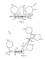
- FIGS. 3 and 4 are simplified side views of exemplary print units 150 formed in accordance with embodiments of the invention.
- the print unit 150 includes a print ribbon 152 and a print head 154.
- the print head 154 is a conventional thermal print head that includes a line of heating elements, which are selectively activated to transfer pixels of print material from the print ribbon 152.
- the print units 150 are configured to print an image (i.e., transfer print material) from the print ribbon 152 to a surface 151 of a substrate 104, such as one of the operative substrates 108 (i.e., print substrate), or one of the reusable cards 130, using the print head 154.
- an image i.e., transfer print material
- a substrate 104 such as one of the operative substrates 108 (i.e., print substrate), or one of the reusable cards 130, using the print head 154.
- the print ribbon 152 is supported between a supply roll 156 and a take-up roll 158.
- FIG. 5 is a simplified top plan view of an exemplary print ribbon 152 in accordance with embodiments of the invention.
- the print ribbon 152 includes a black resin or fusible pigment print panel (K) formed in accordance with conventional resin print panels.
- the print ribbon 152 includes colored dye panels such as, for example, a yellow dye panel (Y), a magenta dye panel (M), and a cyan dye panel (C). In some embodiments, the panels extend in a repeatable series.
- the exemplary print unit 150 of FIG. 3 is generally configured to directly print images to the surface 151 of the substrate 104.
- the print unit 150 may include a conventional print head lift mechanism that is configured to move the print head 154 relative to a processing path 160, along which the substrates 104 are fed in a feed direction 162 using the at least one transport mechanism 112.
- the print unit 150 includes a print platen or roller 164, or other suitable component that supports the substrate 104 and allows the print ribbon 152 to be pressed against the surface 151 of the substrate 104 during a printing operation.
- FIG. 6 is a simplified top plan view illustrating the transference of pixels of print material from the print ribbon 152 to the surface 151 of a substrate 104 during a printing operation using the print unit 150 of FIG. 3 .
- one of the panels of the print ribbon 152 is aligned with the substrate 104, such as through the winding of the print ribbon 152 on to the take-up roll 158 under the control of the controller 120, in accordance with conventional techniques.
- the resistive heating elements of the print head 154 which extend in a longitudinal line across the width of the substrate 104, are selectively activated to transfer a pixel line 166 from the print panel to the substrate 104.
- the pixel line 166 comprises pixels 168 of print material corresponding to the activated heating elements and portions 170 corresponding to deactivated heating elements that do not contain print material.
- the print head 154 prints additional pixel lines 166 to the substrate 104 using the aligned panel of the print ribbon 152.
- Additional color layers of pixels may be printed to the surface 151 by, for example, displacing the print head 154 from the processing path 160, aligning another color panel of the print ribbon 152 with the substrate 104, and feeding the print ribbon 152 and the substrate 104 along the processing path 160 relative to the print head 154, as the print head 154 selectively transfers pixels lines 166 from the print panel to the substrate 104. This may be repeated until the desired image is formed on the surface 151 of the substrate 104.
- the print unit of FIG. 4 is generally configured to perform a reverse-image printing process to print an image to the surface 151 of the substrate 104, in accordance with conventional techniques.
- the print unit 150 in FIG. 4 includes the print ribbon 152, the print head 154, and the print platen or roller 164.
- the image is printed to a transfer ribbon 180, from which the image is transferred to the surface 151 of the substrate 104 through a transfer lamination process.
- the transfer ribbon 180 is supported between a supply roll 182 and a take-up roll 184.
- the transfer ribbon 180 includes a transfer film 186 that is supported on a carrier or backing material 188 and faces the print ribbon 152.
- the print head 154 and the print ribbon 152 are used to print an image to the transfer film 186, in generally the same manner as described above with reference to FIG. 6 .
- the image on the transfer film 186 is then aligned with the surface 151 of the substrate 104, and the image and the substrate 104 are fed past a laminating roller 190.
- the laminating roller 190 presses the transfer film 186 against the surface 151 under the support of a roller 192, and heats the transfer film 186 to bond the imaged transfer film 186 to the surface 151.
- the backing material 188 is then peeled from the portion of the transfer film that is bonded to the substrate 104 leaving the imaged portion of the transfer film 186 attached to the substrate 104 and completing the reverse-image printing process.
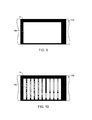
- FIGS. 7 and 8 respectively show a top plan view of a substrate 108 with an image 194 printed on the surface 151, and a top plan view of a resin print panel K of the print ribbon 152 used to form the image 194.
- the image 194 was formed using the print head 154 as discussed above with reference to FIGS. 3 and 4 , by transferring resin pixel lines 166 comprising resin pixels 168 from the print panel K either directly to the surface 151 using the print head 154, or to the transfer film 186.
- the transference of the resin pixels from the panel K produces a residual image 196 on the print panel K that is a negative of the image 194, as shown in FIG. 8 .
- the information printed in the image 194 may be obtained through a review of the residual image 196 on the print panel K of the print ribbon 152. This creates a potential security risk when the image 194 contains sensitive or confidential information.
- one or more images are printed to the reusable card 130 using the print unit 150 (i.e., operative unit 102) to erase or obscure one or more of such residual images 196 on the print ribbon 152.
- the controller 120 is configured to process the reusable or erase card 130 using the print unit 150 to obscure the residual image or images 196 by printing an image to the card 130 using the print head 154 and the portion of the print ribbon 152 comprising the residual image 196.
- the image printed to the card 130 results in the removal of the residual image 196 from the print ribbon 152.
- FIG. 9 is a top plan view of the resin print panel K of FIG. 8 following the printing of the image to the card 130 in step 144.
- this involves activating substantially all of the heating elements of the print head 154 to transfer all of the pixels in the pixel line 166 ( FIG. 6 ) to the card 130.
- the entire residual image 194 may be erased from the print ribbon 152 using this technique in step 144 of the method.
- an image may be printed to the card 130 using the portion of the print ribbon 152 that includes the residual image 196 that effectively obscures the residual image 196.
- a series of lines or bars are printed to the card 130 using the portion of the print ribbon 152 that includes the residual image 196. The printed lines or bars obscure the residual image 196 on the print ribbon 152, as shown in FIG. 10 , which is a top plan view of the panel of FIG. 8 following the printing of the image to the card 130 in step 144.
- Other images or patterns may be printed to the card 130 to ensure proper obscurement of the residual image 196 on the print ribbon 152.
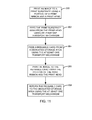
- FIG. 11 is a flowchart illustrating a method of erasing or obscuring a residual image on a print ribbon using the card 130, in accordance with embodiments of the invention.
- an image 194 ( FIG. 7 ) is printed to a substrate 108 using a portion of a print ribbon 152 and a print head 154. This results in the formation of a residual image on the portion of the print ribbon 152 used to form the image 194, as shown in FIG. 8 .
- the printed substrate 108 is fed using the at least one transport mechanism 112 ( FIG. 1 ).
- a reusable or erase card 130 is fed from a dedicated storage area 132 ( FIG. 1 ) using the at least one transport mechanism 112.
- an image is printed to the card 130 using the portion of the print ribbon 152 containing the residual image 196 and the print head 154. This results in the erasure or obscurement of the residual image 196, such as shown in FIGS. 9 and 10 .
- the card 130 is returned to the dedicated storage area 132 using the at least one transport mechanism 112. In some embodiments, this method is repeated each time an image is printed to one of the operative substrates 108.
- the residual image erasing or obscuring process (i.e., FIGS. 2 and 11 ) performed using the card 130 is not performed each time an image is printed to one of the operative substrates 108. Rather, the method is performed after images are printed to two or more of the substrates 108.
- step 144 of the method of FIG. 2 and step 206 of the method of FIG. 11 involve the printing of multiple images to the erase or reusable card 130 using the different portions of the print ribbon 152 used to print images to the substrates 108, to complete the erasure or obscurement of the residual images on the portions of the print ribbon 152.
- the card 130 is returned to the storage area 132 following the printing of the multiple images to the card 130.
- the controller 120 is configured to keep track of the residual images on the print ribbon 152 as the substrates 108 are processed by the device 100. The controller 120 then controls the performance of step 144 or 206 to erase or obscure the residual images using the card 130 as discussed above. In some embodiments, the controller 120 keeps track of the residual images on the print ribbon 152 by storing the necessary information in the memory 122 ( FIG. 1 ) or other location. During the residual image erasing or obscuring step, the controller 120 accesses the memory 122 to identify the locations along the print ribbon 152 requiring erasure or obscurement using the card 130. The controller 120 then controls the device 100 to perform the residual image erasing and obscuring process using the card 130 to erase or obscure the residual images on the print ribbon 152.
- the device 100 is configured to process print jobs, in which multiple substrates 108 are processed by the device including the printing of images to the substrates 108.
- the residual image erasing or obscuring process is performed to erase or obscure existing residual images on the print ribbon 152 using the card 130 either before the device 100 processes the next print job, or immediately after the device 100 processes a print job.
- the device 100 is configured to process print sessions, in which several print jobs are processed by the device 100.
- the residual image erasing or obscuring process is performed using the card 130 either before the start of a new print session, or immediately after the processing of a print session.
- the residual image erasing or obscuring process is performed using the card 130 when the end of the print ribbon 152 has been reached, or when a print ribbon change is requested. In some embodiments, the residual image erasing or obscuring processes are performed using the card 130 during a startup routine of the device 100, or following a reboot or shut down of the device 100. In some embodiments, the residual image erasing or obscuring method is performed using the card 130 in response to a request of a user of the device 100, or an external controller.
- the one or more operative units 102 include a conventional substrate rotator configured to rotate the reusable card 130 and/or the substrates 108.
- the controller 120 uses the substrate rotator to rotate the card 130 to allow both sides of the card 130 to be used in the residual image erasing or obscuring processes described above.
- the controller 120 maintains a count of the number of residual images that have been erased or obscured using the card 130, or other measure. In some embodiments, the controller 120 provides a notification to the user of the device when the count reaches a threshold number. In some embodiments, the card 130 is inverted using the substrate rotator operative unit 102 when the count reaches a threshold number. In some embodiments, when the count reaches the threshold number, the controller 120 prevents further use of the device 100 until a replacement card 130 is installed in the device 100, such as the storage area 132.
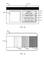
- the reusable card 130 includes memory 210, as shown in the simplified top view of the reusable card 130 provided in FIG. 12 , and the one or more operative units 102 of the device 100 include a conventional data reader/writer configured to read data from and/or write data to the memory 210.
- the controller 120 stores an erase count 212 of the number of times the card 130 is used to erase or obscure a residual image in the memory 210.
- the controller 120 accesses the count 212 from the memory 210 and compares the count 212 to a threshold count to determine whether the card 130 requires replacement. Accordingly, in some embodiments of the method of FIG.
- step 144 involves delivering the card 130 to the data reader/writer operative unit 102 and the controller accesses the memory 210 of the card 130.
- the erase count 212 stored in the memory 210 is read by the controller and compared to a threshold count. If the erase count 212 stored in the memory 210 exceeds the threshold count, the controller 120 notifies the user of the need to replace the card 130, or interrupts operation of the device 100. After the completion of a residual image erasure or obscurement process using the card 130, the controller 120 updates the erase count 212 stored in the memory 210 using the data reader/writer operative unit 102.
- the data reader/writer operative unit 102 of the device 100 is located proximate to the storage area 132.
- the data reader/writer is configured to read data from and/or write data to the memory 210 of the reusable card 130 while the reusable card 130 is in the dedicated storage area 132.
- the reusable card 130 must be fed by the at least one transport mechanism 112 from the storage area 132 to reach the data reader/writer for the memory 210 of the card 130 to be accessed by the controller 120 through the data reader/writer.
- the memory 210 of the reusable card 130 includes a credit count 214 ( FIG. 12 ), which controls the use of the device 100 to process the substrates 108.
- the credit count 214 is a count of the number of operative substrates 108 that may be processed using the device 100.
- the controller 120 accesses the credit count 214 from the memory 210 using the operative unit 102 in the form of a conventional data reader/writer.
- the controller 120 authorizes the processing of the substrates 108 using the device 100 and decrements the credit count 214 using the data reader/writer operative unit 102 accordingly.
- the credit count 214 corresponds to a period of time that the device 100 may be used to process the operative substrates 108, such as a number of hours, or an expiration date.
- the controller 120 uses the data reader/writer to check that the period of time indicated by the credit count 214 stored in the memory 210 of the reusable card 130 has not expired before authorizing use of the device 100 to process one of the substrates 108.
- the controller 120 authorizes the processing of the substrates 108 using the device 100, and decrements the credit count 214 (if applicable) using the data reader/writer operative unit 102.
- the controller 120 notifies the user of the device 100 when the credit count 214 drops below a threshold value or has expired. In some embodiments, the device 100 becomes inoperative until the credit count 214 stored in the memory 210 of the card 130 is renewed, or a new card 130 is installed in the storage area 132 of the device 100 having a valid credit count 214.
- the reusable card 130 is in the form of a configuration card.
- the configuration card 130 includes device settings 216 stored in the memory 210.
- the controller 120 accesses the device settings 216 using a data reader/writer operative unit 102, and modifies the settings 218 of the device 100 stored, for example, in the memory 122 ( FIG. 1 ) based on the device settings 216.
- different settings for the device 100 may be easily programmed through the installation of the appropriate card 130. This allows the device 100 to be delivered to customers in a generic configuration, which may be modified simply by providing the card 130 with the desired device settings 216.
- Exemplary device settings 216 include: a kiosk mode, in which the substrates 108 are retrieved from the output of the device 100 rather than from the substrate supply 106; print settings including an image darkness setting to adjust the intensity of heat used during a printing operation; a top of form (TOF) setting that adjusts the physical position of the substrates 108 relative to the print head 154 at which a printing operation commences to adjust the position of the image printed to the substrate relative to the leading edge of the substrate 108; network communication settings to set, for example, a default IP address, subnet and gateway settings; and other settings that affect the operation of the device 100.
- a kiosk mode in which the substrates 108 are retrieved from the output of the device 100 rather than from the substrate supply 106
- print settings including an image darkness setting to adjust the intensity of heat used during a printing operation
- a top of form (TOF) setting that adjusts the physical position of the substrates 108 relative to the print head 154 at which a printing operation commences to adjust the position of the image printed to the substrate relative
- the device settings 216 include a custom color profile.
- the custom color profile is loaded for use by the device 100, such as by adjusting the settings 218 based on the custom color profile.
- the reusable card 130 includes a security code 220 stored in the memory 210, which is configured to restrict usage of the device 100.
- the controller 120 accesses the security code 220 using the operative unit 102 in the form of a data reader/writer.
- the controller 102 or other application, performs a security check using the security code 220 to determine whether the secured process should be performed by the device 100. If the security code 220 enables the secured process, the device 100 performs the secured process on one or more of the substrates 108. If the security code 220 does not enable the secured process, the device 100 does not perform the secured process on one or more of the substrates 108.
- the reusable card 130 is in the form of a calibration card.
- the controller 120 uses the reusable card 130 to perform a calibration routine on the device 100.
- settings 218 of the device 100 stored, for example, in the memory 122, are adjusted based on the calibration routine performed using the reusable card 130.
- the operative unit 102 is in the form of a conventional card sensor, such as an optical sensor, and the calibration routine performed using the reusable card 130 includes a calibration of the card sensor. For instance, a user selects or enters substrate information corresponding to the operative substrates 108 that are installed in the device 100. In some embodiments, the calibration routine performed using the reusable card 130 operates to calibrate the card sensor to detect the installed operative substrates 108.
- a transparency level of the substrates 108 is obtained from the substrate information.
- the reusable card 130 comprises multiple portions 222, such as portions 222A-D shown in FIG. 13 , each having a different level of transparency corresponding to a transparency level of available operative substrates 108.
- the reusable card 130 is fed from the storage area 132 to the card sensor operative unit 102 such that the portion 222 of the card 130 corresponding to the transparency level identified by the substrate information is positioned for sensing by the card sensor 102.
- the controller 120 performs a calibration routine for the card sensor 102 such that the card sensor operative unit 102 is properly set to detect the transparency level of the installed substrates 108. This may involve, for example, gradually increasing an intensity of a light source of the card sensor until the light is detected by a light sensor on the opposite side of the portion 222 of the card 130.
- the calibration routine is completed when the light sensor detects a threshold intensity level of the light transmitted through the portion 222 of the card 130.
- the reusable card 130 is then returned back to the storage area 132, as indicated at step 146.
- the reusable card 130 is used to perform a magnetic calibration.
- the one or more operative units 102 include a magnetic encoder, such as those configured to write data to, and/or read data from, a magnetic stripe of a card substrate.
- the reusable card 130 includes a magnetic stripe or other magnetic feature 224 ( FIG. 12 ) that is used to configure the magnetic encoder 102 of the device 100 during the method step 144 ( FIG. 2 ).
- the reusable card 130 is fed from the storage area 132 to the magnetic encoding system 102 (step 142) and a calibration routine is performed on the magnetic encoder 102 using the reusable card 130.
- this calibration routine comprises writing magnetic information to, and/or reading magnetic information from, the magnetic feature 224 of the card 130, using the magnetic encoder 102. In some embodiments, settings for the magnetic encoder 102 are adjusted in response to the writing and/or reading processes to complete the calibration routine. Following the calibration routine, the reusable card 130 may be returned to the storage area 132 (step 146).
- the reusable card 130 is in the form of a color calibration card.
- the one or more operative units 102 include a color scanner, such as a linear sensor array, that is configured to verify the color of images printed to the operative substrates 108.
- the reusable card 130 includes a color calibration image 226 ( FIG. 12 ) having known color densities.
- the reusable card 130 is delivered from the storage area 132 to the color scanner 102, at step 142.
- the color calibration image 226 is scanned using the color scanner 102, and the scan is used to calibrate the color scanner 102.
- the reusable card 130 is returned to the storage area 132, at step 146.
- the card 130 is in the form of a cleaning card that includes a sticky or tacky surface that allows the card 130 to collect debris stuck to surfaces of the card path along which the substrates 108 are fed by the one or more transport mechanisms 112, such as rollers 114 ( FIG. 1 ) or other surfaces of the device 100.
- step 144 of the method of FIG. 2 involves feeding the card 130 along the card path using the at least one transport mechanism 112, and collecting debris from surfaces of the card path onto the card 130. The card 130 is then returned to the storage area 132, at step 146, to complete the card path cleaning operation.
- the card 130 is configured to be used in a cleaning operation on the print head 154.
- Embodiments of the print head 154 include the thermal print head described above, and an inkjet print head, which sprays dots of ink and does not use the print ribbon 152.
- the card 130 is fed from the storage area 132 to the print head 154 (step 142), and a cleaning process on the print head 154 using the card 130 (step 144).
- the card 130 is returned to the storage area 132 following the cleaning operation.
- the card 130 is stored within the substrate supply 106 along with at least one bin (e.g., bin 110) of operative substrates 108, as shown in FIG. 1 .
- FIG. 14 is an exploded isometric view of the substrate supply 106 in accordance with embodiments of the invention.
- FIG. 15 is a side view of the substrate supply 106 of FIG. 14 with a portion of the housing removed.
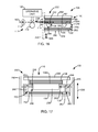
- FIGS. 16 and 17 respectively are simplified side and front views of portions of the substrate supply 106 in a first position, in accordance with embodiments of the invention.
- the substrate supply 106 is configured to operate similarly to that described in International Application No. PCT/US2012/029164 , which is incorporated herein by reference in its entirety.
- the substrate supply 106 includes exterior housing components 228 covering the upper bin 110 and the storage area 132, as shown in FIG. 15 .
- the substrate supply 106 is configured to feed operative substrates 108 from the upper bin 110, and the reusable card 130 from the storage area 132 along a processing path 160. It is understood that the exemplary substrate supply 106 of FIGS. 14-19 may be adjusted to place the storage area 132 above a lower bin 111 ( FIG. 1 ) of the operative substrates 108.
- the feeding of the substrates 108 and the reusable card 130 is achieved using an input feed roller or pinch roller pair 230 (hereinafter “input feed roller") of the at least one transport mechanism 112 positioned between the upper bin 110 and the storage area 132.
- the input feed roller 230 is movable relative to the processing path 160 to selectively feed a bottom card 108A from the upper bin 110, or the reusable card 130 from the storage area 132, for feeding along the processing path 160 using the at least one transport mechanism 112, such as feed rollers 114 ( FIG. 1 ).
- the substrate supply 106 has a first position 232, in which it feeds the bottom card 108A from the upper bin 110 along the processing path 160, as illustrated in FIGS. 16 and 17 . In some embodiments, the substrate supply 106 has a second position 234, in which it feeds the reusable card 130 from the storage area 132 along the processing path 160, as illustrated in FIGS. 18 and 19 .
- the input feed roller 230 is placed in contact with the bottom substrate 108A in the bin 110, and the input feed roller 230 is displaced from the reusable card 130 supported in the storage area 132, when in the first position 232, as shown in FIGS. 16 and 17 .
- the input feed roller 230 is motor driven in the direction indicated by arrow 236 to drive the bottom card 108A for feeding along the processing path 160, as indicated by arrow 238.
- the input feed roller 230 is placed in contact with the reusable card 130 supported in the storage area 132, and is displaced from the bottom card 108A when in the second position 234, as shown in FIGS. 18 and 19 .
- the input feed roller 230 is motor driven in the direction indicated by arrow 240 to drive the reusable card 130 along the processing path 160, as indicated by arrow 242 and shown in FIG. 18 .
- the substrate supply 106 includes the input feed roller 230, one or more cams 246, a substrate engaging table 248 and a sliding bracket 250, as best shown in FIGS. 17 and 19 .
- the input feed roller 230, the one or more cams 246 and the substrate engaging table 248 are attached to, or are supported by the sliding bracket 250.
- the table 248 comprises a top table member 252 and a bottom table member 254 that are separated by a gap 256, as shown in FIGS. 16 and 18 .
- the cams 246, which are displaced from the input feed roller 230 FIGS.
- the cams 246 may rotate or pivot about an axis supported by the bracket 250 that is different from the axis of rotation of the roller 230.
- the upper bin 110 of the substrate supply includes a biasing mechanism 258 that applies a bias force to a stack of substrates 108 supported in the upper bin 110 that directs the stack of substrates 108 toward the top table member 252 and the input feed roller 230.
- a biasing mechanism 258 that applies a bias force to a stack of substrates 108 supported in the upper bin 110 that directs the stack of substrates 108 toward the top table member 252 and the input feed roller 230.
- the biasing mechanism 258 include a spring, a weight (shown) or other suitable biasing mechanisms.
- the storage area 132 is defined by the bottom table member 254 and a support 260 attached to the table 248 or the sliding bracket 250. Accordingly, the storage area 132 moves with movement of the table 248 and/or the sliding bracket 250.
- a gap 262 formed between the members 254 and 260 accommodates a single reusable card 130, as shown in FIG. 16
- the sliding bracket 250 is movable in a vertical direction as illustrated by arrow 266 in FIGS. 16-19 .
- the input feed roller 230 and the table 248 also move along the direction 266 relative to the processing path 160. In some embodiments, this movement of the input feed roller 230 and the table 248 is responsive to movement of the sliding bracket 250.
- the substrate engaging table 248 also moves relative to the input feed roller 230 along the direction 266, in response to movement of the sliding bracket 250.
- the substrate supply 106 includes a main bracket 274 that supports the sliding bracket 250.
- the sliding bracket 250 includes components that cooperate with components of the main bracket 274 to allow the sliding bracket 250 to slide in the direction of arrow 266 relative to the main bracket 274.
- the substrate supply 106 includes a motor 280 and a cam 282, as shown in FIG. 14 .
- the cam 282 includes a cam surface 284 that engages an interior wall of an opening 286 of the sliding bracket 250.
- the motor 280 drives rotation of the cam 282 and the cam surface 284 directs the sliding bracket 250 either upward or downward in the direction 266 relative to the main bracket 274, to move the sliding bracket 250 between its first position 232 and the second position 234.
- the substrate supply 106 is set to the first position 232 by lowering the sliding bracket 250, the input feed roller 230, and the table 248 relative to the processing path 160 along the direction 266.
- the input feed roller 230 is lowered to a position that places a majority of the roller 230 below the processing path 160, as shown in FIG. 16 .
- the lowering of the sliding bracket 250 causes the cams 246 to rotate about an axis, such as the axis of rotation of the input feed roller 230, and direct a surface 286 of the cams 246 to push against a lower inner surface 288 of the bottom table member 254 of the table 248.
- the force applied to the surface 288 by the cams 246 pushes the bottom table member 254 downward in the direction 266 relative to the input feed roller 230.
- the storage area 132 with the card 130 moves downward with the bottom table member 254 in response to the movement of the sliding bracket 250, displacing the reusable card 130 from the input feed roller 230.
- the top table member 252 is lowered relative to the input feed roller 230 responsive to the lowering of the table 248 by the cams 246. This causes the input feed roller 230 to engage the bottom substrate 108A of the upper bin 110 through, for example, an opening in the top table member 252.
- the rotation of the input feed roller 230 in the direction 236 drives the bottom substrate 108A from the substrate supply 106 where it can be received by components of the at least one transport mechanism 112, such as feed rollers 114, for feeding along the processing path 160 to, for example, the one or more operative units 102 for processing.
- the substrate supply 106 may remain in the first position 232 to feed additional substrates 108 from the bin 110 for processing.
- the processed substrates 108 are discharged from the device 100 through a suitable output port.
- the transition of the substrate supply 106 from the first position 232 to the second position 234 involves raising the sliding bracket 250, the input feed roller 230, and the substrate engaging table 248 in the direction 166 relative to the processing path 160, as shown in FIGS. 18 and 19 .
- the input feed roller 230 is raised to a position that places a majority of the roller 230 above the processing path 160.
- the table 248 is raised relative to the input feed roller 230 through the rotation of the cams 246 about the axis of rotation of the input feed roller 230.
- the raising of the sliding bracket 250 causes the cams 246 to rotate or pivot about an axis, such as the axis of the input feed roller 230, and the surface 286 to push against an upper inner surface 290 of the table member 252 to push the table 248, or at least the table member 252, upward in the direction 266 relative to the input feed roller 230.
- This upward movement of the table member 252 pushes the stack of operative substrates 108 upward and displaces the bottom substrate 108A from the input feed roller 230, as shown in FIGS. 18 and 19 .
- the bottom table member 254 and the support 260 of the storage area 132 are raised relative to the input feed roller 230 responsive to the raising of the table 248 by the cams 246.
- This causes the input feed roller 230 to engage the reusable substrate 130 in the storage area 132 through, for example, an opening in the bottom table member 254.
- the rotation of the input feed roller 230 in the direction 240 drives the reusable card 130 out of the substrate supply for feeding along the processing path 160 using the at least one transport mechanism 112, such as feed rollers 114, to complete the method step 142 ( FIG. 2 ), as shown in FIG. 18 .
- the substrate supply 106 may remain in the second position 234 to await the return of the reusable card 130 for feeding back into the storage area 132 to complete step 146 of the method of FIG. 1 .
- the reusable card 130 is returned to the storage area 132 by feeding the reusable card 130 along the processing path 160 toward the substrate supply 106.
- the feed roller 230 is then rotated in the opposite direction from that indicated by arrow 240 ( FIG. 18 ) to drive the reusable card 130 into the storage area 132 and complete step 146 of the method of FIG. 2 .
- the substrate supply 106 may then be returned to the first position 232 to allow the device 100 to process one or more of the operative substrates 108.
Landscapes
- Accessory Devices And Overall Control Thereof (AREA)
Abstract
Description
- Credentials include identification cards, driver's licenses, passports, and other documents. Credential manufacturing devices process substrates, such as plastic card substrates using one or more processing devices form credential products. Common processes performed by such devices on substrates include, for example, printing processes, laminating processes, and data reading and writing processes.
- Printing processes performed by credential manufacturing devices generally operate to print information, such as a photo, account numbers, identification numbers, and other personal information to the substrate. Such printing processes may use a thermal print head and a print ribbon. The print ribbon generally includes a series of colored dye panels (e.g., yellow, cyan and magenta) and a black resin or fusible pigment panel (hereinafter "black resin panel"). The print head includes a line of resistive heating elements, each of which is selectively activated to heat a corresponding portion of one of the panels of the print ribbon and transfer a pixel of print material (i.e., dye or resin) from the panel to the desired surface, such as the surface of the substrate. A wide range of colored pixels may be formed by overlaying pixels of the various colored dyes.
- An image is printed to a surface of the substrate by aligning one of the panels of the print ribbon with the substrate, advancing the panel and the substrate past the print head, and heating portions of the panels to transfer pixels of print material to the surface using the print head. These steps may be repeated for other panels of the print ribbon to complete the printing of the desired image on the substrate.
- When an image is printed using the black resin panel, a negative of the image remains on the black resin panel due to the removal of the black resin. Such residual images may contain confidential information. As a result, it is desirable to obscure or erase residual images in the black resin panels to eliminate the risk of such information being accessed after the used print ribbon is discarded.
- Embodiments of the invention are directed to a substrate processing device, such as a printing device. In some embodiments, the device includes a substrate supply, a reusable card, an operative unit, at least one transport mechanism, and a controller. The substrate supply is configured to support a plurality of operative substrates. The reusable card is stored in a dedicated storage area, which does not receive the operative substrates. The controller is configured to control the at least one transport mechanism and the operative unit to deliver the reusable card from the storage area to the operative unit, to process the reusable card with the operative unit, and return the reusable card to the storage area, multiple times.
- Some embodiments of the invention are directed to a method of obscuring used portions of a print ribbon using the device. In some embodiments, a portion of the print ribbon is used to print an image on an operative or print substrate, which results in the formation of a residual image on the portion of the print ribbon. The operative substrate is then fed using the at least one transport mechanism. The reusable or erase card is fed from the storage area using the at least one transport mechanism. The residual image is obscured by printing an image to the reusable card using the print head and the portion of the print ribbon comprising the residual image. The reusable card is then returned to the storage area using the at least one transport mechanism.
- This Summary is provided to introduce a selection of concepts in a simplified form that are further described below in the Detailed Description. This Summary is not intended to identify key features or essential features of the claimed subject matter, nor is it intended to be used as an aid in determining the scope of the claimed subject matter. The claimed subject matter is not limited to implementations that solve any or all disadvantages noted in the Background.
-
- FIG. 1
- is a simplified diagram of a printing device formed in accordance with embodiments of the invention.
- FIG. 2
- is a flowchart illustrating a method of operating the device in accordance with embodiments of the invention.
- FIGS. 3 and 4
- are simplified side views of exemplary print units formed in accordance with embodiments of the invention.
- FIG. 5
- is a simplified top plan view of an exemplary print ribbon in accordance with embodiments of the invention.
- FIG. 6
- is a simplified top view illustrating a transfer of pixels of print material from a print ribbon to a surface of a substrate during a printing operation using the print unit of
FIG. 3 . - FIGS. 7 and 8
- respectively are a top view of a surface of a substrate with a printed image, and a top view of a resin print panel a print ribbon used to form the printed image.
- FIGS. 9 and 10
- are top views of the resin print panel of
FIG. 8 following the printing of an erasing or obscuring image in accordance with embodiments of the invention. - FIG. 11
- is a flowchart illustrating a method of erasing or obscuring a residual image on a print ribbon using a reusable card, in accordance with embodiments of the invention.
- FIGS. 12 and 13
- are simplified top views of a reusable card in accordance with embodiments of the invention.
- FIG. 14
- is an exploded isometric view of a substrate supply in accordance with embodiments of the invention.
- FIG. 15
- is a side view of the substrate supply of
FIG. 14 with a portion of a housing removed. - FIGS. 16 and 17
- respectively are simplified side and front views of portions of a substrate supply in a first position, in accordance with embodiments of the invention.
- FIGS. 18 and 19
- respectively are simplified side and front views of portions of a substrate supply in a second position, in accordance with embodiments of the invention.
- The ensuing description provides exemplary embodiments only, and is not intended to limit the scope, applicability or configuration of the disclosure. Rather, the ensuing description of the exemplary embodiments will provide those skilled in the art with an enabling description for implementing one or more exemplary embodiments. It being understood that various changes may be made in the function and arrangement of elements without departing from the scope of the invention as set forth in the appended claims.
- Sufficient details are given in the following description to provide those of ordinary skill in the art with a thorough understanding of the embodiments. Well-known and understood components, circuits, processes and techniques may be illustrated in block diagram form or not shown in the drawings in order to avoid obscuring disclosed embodiments in unnecessary detail.
- Also, it is noted that individual embodiments may be described as a process which is depicted as a flowchart, a flow diagram, a data flow diagram, a structure diagram, or a block diagram. Although a flowchart may describe the operations as a sequential process, many of the operations can be performed in parallel or concurrently. In addition, the order of the operations may be rearranged. A process is terminated when its operations are completed, but could have additional steps not included in a figure or described herein. Further, it is understood that embodiments of disclosed process steps include the performance of the process step through the execution of program instructions stored in a tangible medium by one or more processors.
-
FIG. 1 is a simplified diagram of aprinting device 100, such as a credential manufacturing device, formed in accordance with embodiments of the invention. In some embodiments, thedevice 100 includes one or more processing oroperative units 102, each of which are configured to perform a process on a substrate used in the device, generally referred to as 104. Exemplary embodiments of theoperative units 102 include a print unit configured to print an image to a surface of thesubstrate 104, a laminating unit configured to apply an overlaminate material to thesubstrate 104, a data writer configured to write or encode data to thesubstrate 104, a data reader configured to read data stored on thesubstrate 104, a substrate rotator configured to rotate thesubstrate 104, and/or other conventional substrate processing device. - In some embodiments, the
device 100 includes asubstrate hopper 106 configured to contain or support a plurality ofoperative substrates 108, such as credential substrates including card substrates used to form identification cards and other credentials, for example. In some embodiments, thehopper 106 includes multiple bins or containers for supporting theoperative substrates 108, such asbins hopper 106, such asbin 110, are configured to dischargesubstrates 108 for processing by the one or moreoperative units 102 of thedevice 100, while other bins of thehopper 104, such asbin 111, are configured to collectsubstrates 108 after processing by the one or moreoperative units 102. - In some embodiments, the
device 100 includes at least one transport mechanism that is configured to feedindividual substrates 104 from thehopper 106 to the one or moreoperative units 102 for processing. Embodiments of thetransport mechanism 112 includemotorized feed rollers 114 or pinch rollers,motorized platen rollers 118, conveyer belts, and/or other conventional mechanisms used to transportsubstrates 104. - In some embodiments, the
device 100 includes acontroller 120 that is configured to control the components of thedevice 100 and carry out method steps described herein. In some embodiments, thecontroller 120 represents one or more processors that are configured to execute instructions stored inmemory 122, or other location, to perform the method steps. In some embodiments, thecontroller 120 controls the feeding ofindividual substrates 104 through the control of the motors of the at least onetransport mechanism 112 that drives thefeed rollers 114 or other components. In some embodiments, thecontroller 120 controls the operation of the one or moreoperative units 102 to perform the desired process on the substrates, such as a printing process, a laminating process, and/or a data encoding process, for example. Thecontroller 120 may also operate in accordance with controllers of conventional printing devices and credential manufacturing devices, and perform other functions and method steps described herein. - In some embodiments, the
device 100 utilizes one or morereusable cards 130 to perform a process within thedevice 100. In some embodiments, the one or morereusable cards 130 are configured to be stored within adedicated storage area 132. In some embodiments, the term "dedicated storage area," means a storage area that receives or supports the one or morereusable cards 130, but does not receive or support theoperative substrates 106. - In some embodiments, the
storage area 132 is contained within ahousing 134 of thedevice 100, as illustrated inFIG. 1 . In some embodiments, thestorage area 132 is accessible by users of thedevice 100. In other embodiments, the storage area is not readily accessible by the users of thedevice 100. - In some embodiments, the
dedicated storage area 132 may be contained within thesubstrate hopper 106, as indicated in phantom lines inFIG. 1 . In some embodiments, thestorage area 132 may be located below anupper bin 110 of thehopper 106 configured to contain theoperative substrates 108, between theupper bin 110 and thelower bin 111 of thehopper 106, or in another location of thehopper 106. - The reusable card or
cards 130 may take on various forms. In some embodiments, thereusable card 130 is in a similar form as theoperative substrates 108. In some embodiments, thereusable card 130 is different from theoperative substrates 108. For instance, in some embodiments, theoperative substrates 108 are rigid or semi-rigid plastic card substrates, which are used, for example, to form identification cards, and generally require theoperative substrate 108 to be fed along a substantially flat processing path by thetransport mechanism 112. In some embodiments, thereusable card 130 is significantly more flexible than theoperative substrates 108. Accordingly, in some embodiments, thetransport mechanism 112 may significantly flex thereusable substrate 130 to maneuver it to a desired location, such as around rollers or other components. This allows greater flexibility to the location of thestorage area 132 than is possible when using conventionaloperative substrates 108. -
FIG. 2 is a flowchart illustrating a method of operating thedevice 100 in accordance with embodiments of the invention. At 140, areusable card 130 is stored in adedicated storage area 132 of aprinting device 100. Thereusable card 130, thestorage area 132 and theprinting device 100 ofstep 140 are formed in accordance with one or more embodiments described above. - At 142 of the method, the
reusable card 130 is fed from thestorage area 132 using the at least onetransport mechanism 112. In some embodiments, thetransport mechanism 112 utilizes motorized feed rollers or other conventional components to feed thereusable card 130 from thestorage area 132. - At 144, a process is performed using the
reusable card 130. Embodiments of the process that is performed using thereusable card 130 include, for example, a printing process in which print material is transferred from a print ribbon to a surface of the reusable substrate, a data reading or writing process in which data is read from, or written to thereusable card 130, a cleaning process in which a component or components of the device are cleaned using thereusable card 130, a calibration process in which one or more components of thedevice 100 are calibrated using thereusable card 130, and or other process using thereusable card 130. In some embodiments, thereusable card 130 is returned to thestorage area 132 using the at least onetransport mechanism 112 atstep 146. In some embodiments, thereusable card 130 may be discharged from the device following theprocessing step 144. - In some embodiments, the
device 100 includes anoperative unit 102 in the form of a print unit and step 144 involves a printing process using the print unit and thereusable card 130.FIGS. 3 and 4 are simplified side views ofexemplary print units 150 formed in accordance with embodiments of the invention. In some embodiments, theprint unit 150 includes aprint ribbon 152 and aprint head 154. In some embodiments, theprint head 154 is a conventional thermal print head that includes a line of heating elements, which are selectively activated to transfer pixels of print material from theprint ribbon 152. Theprint units 150 are configured to print an image (i.e., transfer print material) from theprint ribbon 152 to asurface 151 of asubstrate 104, such as one of the operative substrates 108 (i.e., print substrate), or one of thereusable cards 130, using theprint head 154. - In some embodiments, the
print ribbon 152 is supported between asupply roll 156 and a take-up roll 158.FIG. 5 is a simplified top plan view of anexemplary print ribbon 152 in accordance with embodiments of the invention. In some embodiments, theprint ribbon 152 includes a black resin or fusible pigment print panel (K) formed in accordance with conventional resin print panels. In some embodiments, theprint ribbon 152 includes colored dye panels such as, for example, a yellow dye panel (Y), a magenta dye panel (M), and a cyan dye panel (C). In some embodiments, the panels extend in a repeatable series. - The
exemplary print unit 150 ofFIG. 3 is generally configured to directly print images to thesurface 151 of thesubstrate 104. In some embodiments, theprint unit 150 may include a conventional print head lift mechanism that is configured to move theprint head 154 relative to aprocessing path 160, along which thesubstrates 104 are fed in afeed direction 162 using the at least onetransport mechanism 112. In some embodiments, theprint unit 150 includes a print platen orroller 164, or other suitable component that supports thesubstrate 104 and allows theprint ribbon 152 to be pressed against thesurface 151 of thesubstrate 104 during a printing operation. -
FIG. 6 is a simplified top plan view illustrating the transference of pixels of print material from theprint ribbon 152 to thesurface 151 of asubstrate 104 during a printing operation using theprint unit 150 ofFIG. 3 . Initially, one of the panels of theprint ribbon 152 is aligned with thesubstrate 104, such as through the winding of theprint ribbon 152 on to the take-up roll 158 under the control of thecontroller 120, in accordance with conventional techniques. The resistive heating elements of theprint head 154, which extend in a longitudinal line across the width of thesubstrate 104, are selectively activated to transfer apixel line 166 from the print panel to thesubstrate 104. Thepixel line 166 comprisespixels 168 of print material corresponding to the activated heating elements andportions 170 corresponding to deactivated heating elements that do not contain print material. As thesubstrate 104 and the print ribbon are fed together in thefeed direction 162 past theprint head 154, theprint head 154 printsadditional pixel lines 166 to thesubstrate 104 using the aligned panel of theprint ribbon 152. Additional color layers of pixels may be printed to thesurface 151 by, for example, displacing theprint head 154 from theprocessing path 160, aligning another color panel of theprint ribbon 152 with thesubstrate 104, and feeding theprint ribbon 152 and thesubstrate 104 along theprocessing path 160 relative to theprint head 154, as theprint head 154 selectively transferspixels lines 166 from the print panel to thesubstrate 104. This may be repeated until the desired image is formed on thesurface 151 of thesubstrate 104. - The print unit of
FIG. 4 is generally configured to perform a reverse-image printing process to print an image to thesurface 151 of thesubstrate 104, in accordance with conventional techniques. As with theprint unit 150 ofFIG. 3 , theprint unit 150 inFIG. 4 includes theprint ribbon 152, theprint head 154, and the print platen orroller 164. However, rather than printing the image directly to thesubstrate 104, the image is printed to atransfer ribbon 180, from which the image is transferred to thesurface 151 of thesubstrate 104 through a transfer lamination process. - In some embodiments, the
transfer ribbon 180 is supported between asupply roll 182 and a take-up roll 184. In some embodiments, thetransfer ribbon 180 includes atransfer film 186 that is supported on a carrier orbacking material 188 and faces theprint ribbon 152. Theprint head 154 and theprint ribbon 152 are used to print an image to thetransfer film 186, in generally the same manner as described above with reference toFIG. 6 . The image on thetransfer film 186 is then aligned with thesurface 151 of thesubstrate 104, and the image and thesubstrate 104 are fed past alaminating roller 190. Thelaminating roller 190 presses thetransfer film 186 against thesurface 151 under the support of aroller 192, and heats thetransfer film 186 to bond the imagedtransfer film 186 to thesurface 151. Thebacking material 188 is then peeled from the portion of the transfer film that is bonded to thesubstrate 104 leaving the imaged portion of thetransfer film 186 attached to thesubstrate 104 and completing the reverse-image printing process. - Occasionally, the printing of images to the
operative substrates 108 using theprint unit 150 results in the formation of a residual image on the portions of theprint ribbon 152 used to print the images. While the delivery of dye from the colored dye panels (Y, M, C) of theprint ribbon 152 do not generally leave behind a traceable record of the printed image on the dye panels of theprint ribbon 152, the transference of the resin from the black panel K leaves behind a record of the printed image. This is illustrated inFIGS. 7 and 8 , which respectively show a top plan view of asubstrate 108 with animage 194 printed on thesurface 151, and a top plan view of a resin print panel K of theprint ribbon 152 used to form theimage 194. In some embodiments, theimage 194 was formed using theprint head 154 as discussed above with reference toFIGS. 3 and 4 , by transferringresin pixel lines 166 comprisingresin pixels 168 from the print panel K either directly to thesurface 151 using theprint head 154, or to thetransfer film 186. The transference of the resin pixels from the panel K produces aresidual image 196 on the print panel K that is a negative of theimage 194, as shown inFIG. 8 . As a result, the information printed in theimage 194 may be obtained through a review of theresidual image 196 on the print panel K of theprint ribbon 152. This creates a potential security risk when theimage 194 contains sensitive or confidential information. - In some embodiments of
step 144 of the method, one or more images are printed to thereusable card 130 using the print unit 150 (i.e., operative unit 102) to erase or obscure one or more of suchresidual images 196 on theprint ribbon 152. In general, thecontroller 120 is configured to process the reusable or erasecard 130 using theprint unit 150 to obscure the residual image orimages 196 by printing an image to thecard 130 using theprint head 154 and the portion of theprint ribbon 152 comprising theresidual image 196. - In some embodiments, the image printed to the
card 130 results in the removal of theresidual image 196 from theprint ribbon 152. This is illustrated inFIG. 9 , which is a top plan view of the resin print panel K ofFIG. 8 following the printing of the image to thecard 130 instep 144. In some embodiments, this involves activating substantially all of the heating elements of theprint head 154 to transfer all of the pixels in the pixel line 166 (FIG. 6 ) to thecard 130. Thus, the entireresidual image 194 may be erased from theprint ribbon 152 using this technique instep 144 of the method. - Alternatively, an image may be printed to the
card 130 using the portion of theprint ribbon 152 that includes theresidual image 196 that effectively obscures theresidual image 196. In some embodiments, a series of lines or bars are printed to thecard 130 using the portion of theprint ribbon 152 that includes theresidual image 196. The printed lines or bars obscure theresidual image 196 on theprint ribbon 152, as shown inFIG. 10 , which is a top plan view of the panel ofFIG. 8 following the printing of the image to thecard 130 instep 144. Other images or patterns may be printed to thecard 130 to ensure proper obscurement of theresidual image 196 on theprint ribbon 152. -
FIG. 11 is a flowchart illustrating a method of erasing or obscuring a residual image on a print ribbon using thecard 130, in accordance with embodiments of the invention. At 200, an image 194 (FIG. 7 ) is printed to asubstrate 108 using a portion of aprint ribbon 152 and aprint head 154. This results in the formation of a residual image on the portion of theprint ribbon 152 used to form theimage 194, as shown inFIG. 8 . At 202, the printedsubstrate 108 is fed using the at least one transport mechanism 112 (FIG. 1 ). At 204, a reusable or erasecard 130 is fed from a dedicated storage area 132 (FIG. 1 ) using the at least onetransport mechanism 112. At 206, an image is printed to thecard 130 using the portion of theprint ribbon 152 containing theresidual image 196 and theprint head 154. This results in the erasure or obscurement of theresidual image 196, such as shown inFIGS. 9 and 10 . At 208, thecard 130 is returned to thededicated storage area 132 using the at least onetransport mechanism 112. In some embodiments, this method is repeated each time an image is printed to one of theoperative substrates 108. - In some embodiments, the residual image erasing or obscuring process (i.e.,
FIGS. 2 and11 ) performed using thecard 130 is not performed each time an image is printed to one of theoperative substrates 108. Rather, the method is performed after images are printed to two or more of thesubstrates 108. Thus, in some embodiments, step 144 of the method ofFIG. 2 and step 206 of the method ofFIG. 11 involve the printing of multiple images to the erase orreusable card 130 using the different portions of theprint ribbon 152 used to print images to thesubstrates 108, to complete the erasure or obscurement of the residual images on the portions of theprint ribbon 152. In some embodiments, thecard 130 is returned to thestorage area 132 following the printing of the multiple images to thecard 130. - In some embodiments, the
controller 120 is configured to keep track of the residual images on theprint ribbon 152 as thesubstrates 108 are processed by thedevice 100. Thecontroller 120 then controls the performance ofstep card 130 as discussed above. In some embodiments, thecontroller 120 keeps track of the residual images on theprint ribbon 152 by storing the necessary information in the memory 122 (FIG. 1 ) or other location. During the residual image erasing or obscuring step, thecontroller 120 accesses thememory 122 to identify the locations along theprint ribbon 152 requiring erasure or obscurement using thecard 130. Thecontroller 120 then controls thedevice 100 to perform the residual image erasing and obscuring process using thecard 130 to erase or obscure the residual images on theprint ribbon 152. - In some embodiments, the
device 100 is configured to process print jobs, in whichmultiple substrates 108 are processed by the device including the printing of images to thesubstrates 108. In some embodiments, the residual image erasing or obscuring process is performed to erase or obscure existing residual images on theprint ribbon 152 using thecard 130 either before thedevice 100 processes the next print job, or immediately after thedevice 100 processes a print job. - In some embodiments, the
device 100 is configured to process print sessions, in which several print jobs are processed by thedevice 100. In some embodiments, the residual image erasing or obscuring process is performed using thecard 130 either before the start of a new print session, or immediately after the processing of a print session. - In some embodiments, the residual image erasing or obscuring process is performed using the
card 130 when the end of theprint ribbon 152 has been reached, or when a print ribbon change is requested. In some embodiments, the residual image erasing or obscuring processes are performed using thecard 130 during a startup routine of thedevice 100, or following a reboot or shut down of thedevice 100. In some embodiments, the residual image erasing or obscuring method is performed using thecard 130 in response to a request of a user of thedevice 100, or an external controller. - In some embodiments, the one or more
operative units 102 include a conventional substrate rotator configured to rotate thereusable card 130 and/or thesubstrates 108. In some embodiments, thecontroller 120 uses the substrate rotator to rotate thecard 130 to allow both sides of thecard 130 to be used in the residual image erasing or obscuring processes described above. - In some embodiments, it is desirable to limit the number of times the
reusable card 130 may be used to erase or obscure residual images on theprint ribbon 152. In some embodiments, thecontroller 120 maintains a count of the number of residual images that have been erased or obscured using thecard 130, or other measure. In some embodiments, thecontroller 120 provides a notification to the user of the device when the count reaches a threshold number. In some embodiments, thecard 130 is inverted using the substrate rotatoroperative unit 102 when the count reaches a threshold number. In some embodiments, when the count reaches the threshold number, thecontroller 120 prevents further use of thedevice 100 until areplacement card 130 is installed in thedevice 100, such as thestorage area 132. - In some embodiments, the
reusable card 130 includesmemory 210, as shown in the simplified top view of thereusable card 130 provided inFIG. 12 , and the one or moreoperative units 102 of thedevice 100 include a conventional data reader/writer configured to read data from and/or write data to thememory 210. In some embodiments, thecontroller 120 stores an erasecount 212 of the number of times thecard 130 is used to erase or obscure a residual image in thememory 210. In some embodiments, thecontroller 120 accesses thecount 212 from thememory 210 and compares thecount 212 to a threshold count to determine whether thecard 130 requires replacement. Accordingly, in some embodiments of the method ofFIG. 2 described above,step 144 involves delivering thecard 130 to the data reader/writer operative unit 102 and the controller accesses thememory 210 of thecard 130. The erasecount 212 stored in thememory 210 is read by the controller and compared to a threshold count. If the erasecount 212 stored in thememory 210 exceeds the threshold count, thecontroller 120 notifies the user of the need to replace thecard 130, or interrupts operation of thedevice 100. After the completion of a residual image erasure or obscurement process using thecard 130, thecontroller 120 updates the erasecount 212 stored in thememory 210 using the data reader/writer operative unit 102. - In some embodiments, the data reader/
writer operative unit 102 of thedevice 100 is located proximate to thestorage area 132. In some embodiments, the data reader/writer is configured to read data from and/or write data to thememory 210 of thereusable card 130 while thereusable card 130 is in thededicated storage area 132. In some embodiments, thereusable card 130 must be fed by the at least onetransport mechanism 112 from thestorage area 132 to reach the data reader/writer for thememory 210 of thecard 130 to be accessed by thecontroller 120 through the data reader/writer. - In some embodiments, the
memory 210 of thereusable card 130 includes a credit count 214 (FIG. 12 ), which controls the use of thedevice 100 to process thesubstrates 108. In some embodiments, the credit count 214 is a count of the number ofoperative substrates 108 that may be processed using thedevice 100. In some embodiments of step 144 (FIG. 2 ), thecontroller 120 accesses the credit count 214 from thememory 210 using theoperative unit 102 in the form of a conventional data reader/writer. In some embodiments, if the credit count 214 is greater than the number ofsubstrates 108 to be processed, thecontroller 120 authorizes the processing of thesubstrates 108 using thedevice 100 and decrements the credit count 214 using the data reader/writer operative unit 102 accordingly. - In some embodiments, the credit count 214 corresponds to a period of time that the
device 100 may be used to process theoperative substrates 108, such as a number of hours, or an expiration date. In some embodiments of step 144 (FIG. 2 ), thecontroller 120 uses the data reader/writer to check that the period of time indicated by the credit count 214 stored in thememory 210 of thereusable card 130 has not expired before authorizing use of thedevice 100 to process one of thesubstrates 108. In some embodiments, if the period of time has not expired, thecontroller 120 authorizes the processing of thesubstrates 108 using thedevice 100, and decrements the credit count 214 (if applicable) using the data reader/writer operative unit 102. - In some embodiments, the
controller 120 notifies the user of thedevice 100 when the credit count 214 drops below a threshold value or has expired. In some embodiments, thedevice 100 becomes inoperative until the credit count 214 stored in thememory 210 of thecard 130 is renewed, or anew card 130 is installed in thestorage area 132 of thedevice 100 having a valid credit count 214. - In some embodiments, the
reusable card 130 is in the form of a configuration card. In some embodiments, theconfiguration card 130 includesdevice settings 216 stored in thememory 210. In some embodiments of step 144 (FIG. 2 ), thecontroller 120 accesses thedevice settings 216 using a data reader/writer operative unit 102, and modifies thesettings 218 of thedevice 100 stored, for example, in the memory 122 (FIG. 1 ) based on thedevice settings 216. Thus, different settings for thedevice 100 may be easily programmed through the installation of theappropriate card 130. This allows thedevice 100 to be delivered to customers in a generic configuration, which may be modified simply by providing thecard 130 with the desireddevice settings 216.Exemplary device settings 216 include: a kiosk mode, in which thesubstrates 108 are retrieved from the output of thedevice 100 rather than from thesubstrate supply 106; print settings including an image darkness setting to adjust the intensity of heat used during a printing operation; a top of form (TOF) setting that adjusts the physical position of thesubstrates 108 relative to theprint head 154 at which a printing operation commences to adjust the position of the image printed to the substrate relative to the leading edge of thesubstrate 108; network communication settings to set, for example, a default IP address, subnet and gateway settings; and other settings that affect the operation of thedevice 100. - In some embodiments, the
device settings 216 include a custom color profile. In some embodiments of themethod step 144, the custom color profile is loaded for use by thedevice 100, such as by adjusting thesettings 218 based on the custom color profile. - In some embodiments, the
reusable card 130 includes a security code 220 stored in thememory 210, which is configured to restrict usage of thedevice 100. In some embodiments of the method step 144 (FIG. 1 ), when a user of thedevice 100 attempts to perform a secured process on one of thesubstrates 108 with thedevice 100, such as a printing or data writing process, thecontroller 120 accesses the security code 220 using theoperative unit 102 in the form of a data reader/writer. Thecontroller 102, or other application, performs a security check using the security code 220 to determine whether the secured process should be performed by thedevice 100. If the security code 220 enables the secured process, thedevice 100 performs the secured process on one or more of thesubstrates 108. If the security code 220 does not enable the secured process, thedevice 100 does not perform the secured process on one or more of thesubstrates 108. - In some embodiments, the
reusable card 130 is in the form of a calibration card. In some embodiments of themethod step 144, thecontroller 120 uses thereusable card 130 to perform a calibration routine on thedevice 100. In some embodiments,settings 218 of thedevice 100 stored, for example, in thememory 122, are adjusted based on the calibration routine performed using thereusable card 130. - In some embodiments, the
operative unit 102 is in the form of a conventional card sensor, such as an optical sensor, and the calibration routine performed using thereusable card 130 includes a calibration of the card sensor. For instance, a user selects or enters substrate information corresponding to theoperative substrates 108 that are installed in thedevice 100. In some embodiments, the calibration routine performed using thereusable card 130 operates to calibrate the card sensor to detect the installedoperative substrates 108. - In some embodiments, a transparency level of the
substrates 108 is obtained from the substrate information. In some embodiments, thereusable card 130 comprises multiple portions 222, such asportions 222A-D shown inFIG. 13 , each having a different level of transparency corresponding to a transparency level of availableoperative substrates 108. In some embodiments ofstep 142 of the method, thereusable card 130 is fed from thestorage area 132 to the card sensoroperative unit 102 such that the portion 222 of thecard 130 corresponding to the transparency level identified by the substrate information is positioned for sensing by thecard sensor 102. - In some embodiments of
step 144 of the method, thecontroller 120 performs a calibration routine for thecard sensor 102 such that the card sensoroperative unit 102 is properly set to detect the transparency level of the installedsubstrates 108. This may involve, for example, gradually increasing an intensity of a light source of the card sensor until the light is detected by a light sensor on the opposite side of the portion 222 of thecard 130. The calibration routine is completed when the light sensor detects a threshold intensity level of the light transmitted through the portion 222 of thecard 130. Thereusable card 130 is then returned back to thestorage area 132, as indicated atstep 146. - In accordance with another embodiment, the
reusable card 130 is used to perform a magnetic calibration. In accordance with this embodiment, the one or moreoperative units 102 include a magnetic encoder, such as those configured to write data to, and/or read data from, a magnetic stripe of a card substrate. In some embodiments, thereusable card 130 includes a magnetic stripe or other magnetic feature 224 (FIG. 12 ) that is used to configure themagnetic encoder 102 of thedevice 100 during the method step 144 (FIG. 2 ). In some embodiments, thereusable card 130 is fed from thestorage area 132 to the magnetic encoding system 102 (step 142) and a calibration routine is performed on themagnetic encoder 102 using thereusable card 130. In some embodiments, this calibration routine comprises writing magnetic information to, and/or reading magnetic information from, themagnetic feature 224 of thecard 130, using themagnetic encoder 102. In some embodiments, settings for themagnetic encoder 102 are adjusted in response to the writing and/or reading processes to complete the calibration routine. Following the calibration routine, thereusable card 130 may be returned to the storage area 132 (step 146). - In some embodiments, the
reusable card 130 is in the form of a color calibration card. Here, the one or moreoperative units 102 include a color scanner, such as a linear sensor array, that is configured to verify the color of images printed to theoperative substrates 108. In some embodiments, thereusable card 130 includes a color calibration image 226 (FIG. 12 ) having known color densities. In some embodiments of the method ofFIG. 2 , thereusable card 130 is delivered from thestorage area 132 to thecolor scanner 102, atstep 142. In some embodiments ofstep 144, thecolor calibration image 226 is scanned using thecolor scanner 102, and the scan is used to calibrate thecolor scanner 102. In some embodiments, thereusable card 130 is returned to thestorage area 132, atstep 146. - After a period of use, such as after processing 150-200 of the
substrates 108, it may be desirable to perform one or more cleaning operations to ensure proper operation of thedevice 100. In some embodiments, thecard 130 is in the form of a cleaning card that includes a sticky or tacky surface that allows thecard 130 to collect debris stuck to surfaces of the card path along which thesubstrates 108 are fed by the one ormore transport mechanisms 112, such as rollers 114 (FIG. 1 ) or other surfaces of thedevice 100. In some embodiments, step 144 of the method ofFIG. 2 involves feeding thecard 130 along the card path using the at least onetransport mechanism 112, and collecting debris from surfaces of the card path onto thecard 130. Thecard 130 is then returned to thestorage area 132, atstep 146, to complete the card path cleaning operation. - In some embodiments, the
card 130 is configured to be used in a cleaning operation on theprint head 154. Embodiments of theprint head 154 include the thermal print head described above, and an inkjet print head, which sprays dots of ink and does not use theprint ribbon 152. In some embodiments of the method ofFIG. 2 , thecard 130 is fed from thestorage area 132 to the print head 154 (step 142), and a cleaning process on theprint head 154 using the card 130 (step 144). In some embodiments, thecard 130 is returned to thestorage area 132 following the cleaning operation. - As mentioned above, in some embodiments, the
card 130 is stored within thesubstrate supply 106 along with at least one bin (e.g., bin 110) ofoperative substrates 108, as shown inFIG. 1 . Some exemplary embodiments of thesubstrate supply 106 will be described with reference toFIGS. 14-19 .FIG. 14 is an exploded isometric view of thesubstrate supply 106 in accordance with embodiments of the invention.FIG. 15 is a side view of thesubstrate supply 106 ofFIG. 14 with a portion of the housing removed.FIGS. 16 and 17 respectively are simplified side and front views of portions of thesubstrate supply 106 in a first position, in accordance with embodiments of the invention.FIGS. 18 and 19 respectively are simplified side and front views of portions of thesubstrate supply 106 in a second position, in accordance with embodiments of the invention. In some embodiments, thesubstrate supply 106 is configured to operate similarly to that described in International Application No.PCT/US2012/029164 , which is incorporated herein by reference in its entirety. - In some embodiments, the
substrate supply 106 includesexterior housing components 228 covering theupper bin 110 and thestorage area 132, as shown inFIG. 15 . In some embodiments, thesubstrate supply 106 is configured to feedoperative substrates 108 from theupper bin 110, and thereusable card 130 from thestorage area 132 along aprocessing path 160. It is understood that theexemplary substrate supply 106 ofFIGS. 14-19 may be adjusted to place thestorage area 132 above a lower bin 111 (FIG. 1 ) of theoperative substrates 108. - In some embodiments, the feeding of the
substrates 108 and thereusable card 130 is achieved using an input feed roller or pinch roller pair 230 (hereinafter "input feed roller") of the at least onetransport mechanism 112 positioned between theupper bin 110 and thestorage area 132. In some embodiments, theinput feed roller 230 is movable relative to theprocessing path 160 to selectively feed abottom card 108A from theupper bin 110, or thereusable card 130 from thestorage area 132, for feeding along theprocessing path 160 using the at least onetransport mechanism 112, such as feed rollers 114 (FIG. 1 ). - In some embodiments, the
substrate supply 106 has afirst position 232, in which it feeds thebottom card 108A from theupper bin 110 along theprocessing path 160, as illustrated inFIGS. 16 and 17 . In some embodiments, thesubstrate supply 106 has asecond position 234, in which it feeds thereusable card 130 from thestorage area 132 along theprocessing path 160, as illustrated inFIGS. 18 and 19 . - In some embodiments, the
input feed roller 230 is placed in contact with thebottom substrate 108A in thebin 110, and theinput feed roller 230 is displaced from thereusable card 130 supported in thestorage area 132, when in thefirst position 232, as shown inFIGS. 16 and 17 . When in thefirst position 232, theinput feed roller 230 is motor driven in the direction indicated byarrow 236 to drive thebottom card 108A for feeding along theprocessing path 160, as indicated byarrow 238. - In some embodiments, the
input feed roller 230 is placed in contact with thereusable card 130 supported in thestorage area 132, and is displaced from thebottom card 108A when in thesecond position 234, as shown inFIGS. 18 and 19 . When in thesecond position 234, theinput feed roller 230 is motor driven in the direction indicated byarrow 240 to drive thereusable card 130 along theprocessing path 160, as indicated byarrow 242 and shown inFIG. 18 . - In some embodiments, the
substrate supply 106 includes theinput feed roller 230, one ormore cams 246, a substrate engaging table 248 and a slidingbracket 250, as best shown inFIGS. 17 and19 . In some embodiments, theinput feed roller 230, the one ormore cams 246 and the substrate engaging table 248 are attached to, or are supported by the slidingbracket 250. In some embodiments, the table 248 comprises atop table member 252 and abottom table member 254 that are separated by agap 256, as shown inFIGS. 16 and18 . In some embodiments, thecams 246, which are displaced from the input feed roller 230 (FIGS. 16 and18 ) are configured to rotate or pivot about the axis of theinput feed roller 230 independent of the rotation of theinput feed roller 230. In some embodiments, thecams 246 may rotate or pivot about an axis supported by thebracket 250 that is different from the axis of rotation of theroller 230. - In some embodiments, the
upper bin 110 of the substrate supply includes abiasing mechanism 258 that applies a bias force to a stack ofsubstrates 108 supported in theupper bin 110 that directs the stack ofsubstrates 108 toward thetop table member 252 and theinput feed roller 230. Exemplary embodiments of thebiasing mechanism 258 include a spring, a weight (shown) or other suitable biasing mechanisms. - In some embodiments, the
storage area 132 is defined by thebottom table member 254 and asupport 260 attached to the table 248 or the slidingbracket 250. Accordingly, thestorage area 132 moves with movement of the table 248 and/or the slidingbracket 250. In some embodiments, agap 262 formed between themembers reusable card 130, as shown inFIG. 16 - In some embodiments, the sliding
bracket 250 is movable in a vertical direction as illustrated byarrow 266 inFIGS. 16-19 . In some embodiments, theinput feed roller 230 and the table 248 also move along thedirection 266 relative to theprocessing path 160. In some embodiments, this movement of theinput feed roller 230 and the table 248 is responsive to movement of the slidingbracket 250. In some embodiments, the substrate engaging table 248 also moves relative to theinput feed roller 230 along thedirection 266, in response to movement of the slidingbracket 250. - In some embodiments, the
substrate supply 106 includes amain bracket 274 that supports the slidingbracket 250. In some embodiments, the slidingbracket 250 includes components that cooperate with components of themain bracket 274 to allow the slidingbracket 250 to slide in the direction ofarrow 266 relative to themain bracket 274. In some embodiments, thesubstrate supply 106 includes amotor 280 and acam 282, as shown inFIG. 14 . Thecam 282 includes acam surface 284 that engages an interior wall of anopening 286 of the slidingbracket 250. Themotor 280 drives rotation of thecam 282 and thecam surface 284 directs the slidingbracket 250 either upward or downward in thedirection 266 relative to themain bracket 274, to move the slidingbracket 250 between itsfirst position 232 and thesecond position 234. - In some embodiments, the
substrate supply 106 is set to thefirst position 232 by lowering the slidingbracket 250, theinput feed roller 230, and the table 248 relative to theprocessing path 160 along thedirection 266. In some embodiments, theinput feed roller 230 is lowered to a position that places a majority of theroller 230 below theprocessing path 160, as shown inFIG. 16 . In some embodiments, the lowering of the slidingbracket 250 causes thecams 246 to rotate about an axis, such as the axis of rotation of theinput feed roller 230, and direct asurface 286 of thecams 246 to push against a lowerinner surface 288 of thebottom table member 254 of the table 248. The force applied to thesurface 288 by thecams 246 pushes thebottom table member 254 downward in thedirection 266 relative to theinput feed roller 230. In some embodiments, thestorage area 132 with thecard 130 moves downward with thebottom table member 254 in response to the movement of the slidingbracket 250, displacing thereusable card 130 from theinput feed roller 230. Additionally, thetop table member 252 is lowered relative to theinput feed roller 230 responsive to the lowering of the table 248 by thecams 246. This causes theinput feed roller 230 to engage thebottom substrate 108A of theupper bin 110 through, for example, an opening in thetop table member 252. The rotation of theinput feed roller 230 in thedirection 236 drives thebottom substrate 108A from thesubstrate supply 106 where it can be received by components of the at least onetransport mechanism 112, such asfeed rollers 114, for feeding along theprocessing path 160 to, for example, the one or moreoperative units 102 for processing. Thesubstrate supply 106 may remain in thefirst position 232 to feedadditional substrates 108 from thebin 110 for processing. In some embodiments, the processedsubstrates 108 are discharged from thedevice 100 through a suitable output port. - In some embodiments, the transition of the
substrate supply 106 from thefirst position 232 to thesecond position 234 involves raising the slidingbracket 250, theinput feed roller 230, and the substrate engaging table 248 in thedirection 166 relative to theprocessing path 160, as shown inFIGS. 18 and 19 . In some embodiments, theinput feed roller 230 is raised to a position that places a majority of theroller 230 above theprocessing path 160. Additionally, the table 248 is raised relative to theinput feed roller 230 through the rotation of thecams 246 about the axis of rotation of theinput feed roller 230. In some embodiments, the raising of the slidingbracket 250 causes thecams 246 to rotate or pivot about an axis, such as the axis of theinput feed roller 230, and thesurface 286 to push against an upperinner surface 290 of thetable member 252 to push the table 248, or at least thetable member 252, upward in thedirection 266 relative to theinput feed roller 230. This upward movement of thetable member 252 pushes the stack ofoperative substrates 108 upward and displaces thebottom substrate 108A from theinput feed roller 230, as shown inFIGS. 18 and 19 . - Additionally, the
bottom table member 254 and thesupport 260 of thestorage area 132 are raised relative to theinput feed roller 230 responsive to the raising of the table 248 by thecams 246. This causes theinput feed roller 230 to engage thereusable substrate 130 in thestorage area 132 through, for example, an opening in thebottom table member 254. The rotation of theinput feed roller 230 in thedirection 240 drives thereusable card 130 out of the substrate supply for feeding along theprocessing path 160 using the at least onetransport mechanism 112, such asfeed rollers 114, to complete the method step 142 (FIG. 2 ), as shown inFIG. 18 . - The
substrate supply 106 may remain in thesecond position 234 to await the return of thereusable card 130 for feeding back into thestorage area 132 to completestep 146 of the method ofFIG. 1 . In some embodiments, thereusable card 130 is returned to thestorage area 132 by feeding thereusable card 130 along theprocessing path 160 toward thesubstrate supply 106. Thefeed roller 230 is then rotated in the opposite direction from that indicated by arrow 240 (FIG. 18 ) to drive thereusable card 130 into thestorage area 132 andcomplete step 146 of the method ofFIG. 2 . Thesubstrate supply 106 may then be returned to thefirst position 232 to allow thedevice 100 to process one or more of theoperative substrates 108. - Although the present invention has been described with reference to preferred embodiments, workers skilled in the art will recognize that changes may be made in form and detail without departing from the spirit and scope of the invention.
Claims (15)
- A printing device comprising:a substrate supply configured to support a plurality of print substrates;a reusable card stored in a dedicated storage area, which does not receive the print substrates;an operative unit;at least one transport mechanism; anda controller configured to control the at least one transport mechanism and the operative unit to deliver the reusable card from the storage area to the operative unit, to process the reusable card with the operative unit, and return the reusable card to the storage area, multiple times.
- The device of claim 1, wherein the device includes a housing and the storage area is internal to the housing.
- The device of claim 1 or 2, further comprising a substrate hopper containing the substrate supply and the storage area.
- The device of one of the preceding claims, wherein the reusable card is selected from the group consisting of a cleaning card, a security card, and a calibration card.
- The device of one of the preceding claims, further comprising a print ribbon and wherein:the reusable card comprises an erase card;the operative unit comprises a print head; andthe controller is configured to process the reusable card using the operative unit including obscuring a residual image, which was previously formed on a print ribbon responsive to printing an image to a substrate, by printing an image to the erase card using the print head and a portion of the print ribbon comprising the residual image.
- The device of one of the preceding claims, wherein:the device includes a memory, and a usage count stored in the memory indicating an amount of usage of the reusable card; andthe controller is configured to update the usage count in response to usage of the reusable card.
- The device of claim 5, wherein the memory is attached to the reusable card.
- A method of operating a printing device as defined in one of the preceding claims 1 to 7, comprising:storing a reusable card in a storage area of the printing device;performing at least one process using the reusable card comprising:feeding the reusable card from the storage area using at least one transport mechanism of the printing device;performing the at least one process using the reusable card; andreturning the reusable card to the storage area using the at least one transport mechanism.
- The method of claim 8, wherein performing the at least one process using the reusable card comprises performing a process using the reusable card selected from the group consisting of obscuring at least one residual image on a print ribbon of the device; cleaning a component of the printing device; reading data from the reusable card using a data reader of the printing device; writing data to the reusable card using a data writer of the printing device; calibrating a component of the printing device; and performing a security check.
- The method of claim 8 or 9, wherein performing at least one process on the reusable card occurs:before or at the end of a print operation performed by the printing device;before or at the end of a print session comprising multiple print operations performed by the printing device;when an end of the print ribbon has been reached or when a print ribbon change is requested;in response to starting the printing device, rebooting the printing device, or shutting-down the printing device; orin response to a request from a user or an external controller.
- The method of one of the preceding claims 8 to 10, further comprising tracking an amount of usage of the reusable card in memory of the printing device or the reusable card using a controller of the printing device.
- The method of claim 11, wherein the controller is configured to trigger an alert when the amount of usage of the reusable card exceeds a predetermined value.
- The method of one of the preceding claims 8 to 12, wherein:the printing device includes a print ribbon and a print head;the method includes performing a print operation comprising:feeding a substrate from a substrate supply, which is separate from the storage area, using the at least one transport mechanism; and printing a first image on the substrate using a portion of the print ribbon and the print head;wherein the portion of the print ribbon includes a residual image corresponding to the printed first image; andperforming the at least one process using the reusable card comprises obscuring the residual image including printing a second image to the erase card using the print head and the portion of the print ribbon comprising the residual image.
- The method of claim 13, wherein performing the at least one process using the reusable card comprises performing a process using the reusable card selected from the group consisting of cleaning a component of the printing device; reading data from the reusable card using a data reader of the printing device; writing data to the reusable card using a data writer of the printing device; calibrating a component of the printing device; and performing a security check.
- The method of one of the preceding claims 8 to 14, wherein:the printing device includes a print ribbon and a print head;the method includes performing a plurality of print operations comprising:delivering a substrate from a substrate supply, which is separate from the storage area, using the at least one transport mechanism;printing an image on the substrate using a portion of the print ribbon and the print head, wherein the portion of the print ribbon includes a residual image corresponding to the printed image; andrepeating the delivering and printing steps a limited number of times; and performing the at least one process using the reusable card comprises obscuring theresidual images on the print ribbon including printing at least one obscuring image to the reusable card using the print head and the print ribbon.
Applications Claiming Priority (1)
| Application Number | Priority Date | Filing Date | Title |
|---|---|---|---|
| CH12952013 | 2013-07-22 |
Publications (2)
| Publication Number | Publication Date |
|---|---|
| EP2829407A1 true EP2829407A1 (en) | 2015-01-28 |
| EP2829407B1 EP2829407B1 (en) | 2016-08-24 |
Family
ID=51211023
Family Applications (1)
| Application Number | Title | Priority Date | Filing Date |
|---|---|---|---|
| EP14175845.8A Not-in-force EP2829407B1 (en) | 2013-07-22 | 2014-07-04 | Printing device having reusable card |
Country Status (3)
| Country | Link |
|---|---|
| US (1) | US8933978B1 (en) |
| EP (1) | EP2829407B1 (en) |
| ES (1) | ES2595635T3 (en) |
Families Citing this family (7)
| Publication number | Priority date | Publication date | Assignee | Title |
|---|---|---|---|---|
| WO2018063158A1 (en) * | 2016-09-27 | 2018-04-05 | Hewlett-Packard Development Company, L.P. | Print pattern & algorithm for automatic ink mix detection |
| BE1024741B1 (en) * | 2016-11-15 | 2018-06-21 | Pom Nv | IDENTIFICATION BY SCANNING A BARCODE |
| US10744806B2 (en) | 2018-06-04 | 2020-08-18 | Entrust Datacard Corporation | Obscuring residual images on print ribbons |
| US11110492B2 (en) * | 2018-06-15 | 2021-09-07 | Kicteam, Inc. | Plunger card for cleaning currency handling device |
| CN116438540A (en) | 2020-10-01 | 2023-07-14 | 恩图鲁斯特有限公司 | Print Ribbon Residual Image Scrambling Using Metadata |
| CN116834454A (en) * | 2023-07-06 | 2023-10-03 | 中国工商银行股份有限公司 | Method, system, apparatus, medium and program product for removing residual information in color ribbon |
| CN118254484B (en) * | 2024-02-19 | 2025-01-10 | 得实打印机(江门)有限公司 | YMC ribbon printing information erasing method, printing device and related equipment |
Citations (4)
| Publication number | Priority date | Publication date | Assignee | Title |
|---|---|---|---|---|
| JPS5985777A (en) * | 1983-09-14 | 1984-05-17 | Toshiba Corp | Thermal transfer printer |
| US20030024422A1 (en) * | 2000-01-21 | 2003-02-06 | Pribula Martin A. | Identification card printer |
| EP1884368A1 (en) * | 2006-08-04 | 2008-02-06 | CTS Electronics S.P.A. | Method and device for removing traces of personal data in an equipment for issuing identification cards or badges |
| US20120306986A1 (en) * | 2011-06-06 | 2012-12-06 | Source Technologies, Llc | Printing ribbon security apparatus and method |
Family Cites Families (16)
| Publication number | Priority date | Publication date | Assignee | Title |
|---|---|---|---|---|
| JPS609785A (en) | 1983-06-30 | 1985-01-18 | Toshiba Corp | Recorder |
| JPS60147372A (en) | 1984-01-13 | 1985-08-03 | Canon Inc | Thermal transfer recorder |
| JPS6161877A (en) | 1984-08-31 | 1986-03-29 | Mita Ind Co Ltd | Method and apparatus for removing print mark in thermal printer |
| JPS63254092A (en) | 1987-04-13 | 1988-10-20 | Matsushita Graphic Commun Syst Inc | Method for erasing printing trace mark of thermal transfer ink sheet |
| US4916739A (en) * | 1988-03-31 | 1990-04-10 | Jerry R. Iggulden | Adhesive photocopyable transparency for use in a secure facsimile transmission system |
| JPH06147372A (en) | 1992-11-10 | 1994-05-27 | Daikin Ind Ltd | Flare-type pipe connection gas leak detection structure |
| US5634731A (en) | 1994-03-04 | 1997-06-03 | Dai Nippon Printing Co., Ltd. | Method and apparatus for thermal transfer printing |
| DE19549376A1 (en) | 1995-03-07 | 1996-09-26 | Francotyp Postalia Gmbh | System for thermotransfer printing procedure |
| JPH1086424A (en) | 1996-09-20 | 1998-04-07 | Fujitsu Ltd | Thermal transfer recording device |
| US6106910A (en) | 1998-06-30 | 2000-08-22 | Ncr Corporation | Print media with near infrared fluorescent sense mark and printer therefor |
| US6387846B1 (en) | 1998-09-10 | 2002-05-14 | Dai Nippon Printing Co., Ltd. | Thermal transfer sheet, thermal transfer recording method, and thermal transfer recording system |
| US7878505B2 (en) | 2003-08-19 | 2011-02-01 | Hid Global Corporation | Credential substrate rotator and processing module |
| JP4512456B2 (en) | 2004-09-08 | 2010-07-28 | 株式会社リコー | Reusable recording material for electrophotography and manufacturing method thereof |
| GB0610094D0 (en) | 2006-05-19 | 2006-06-28 | The Technology Partnership Plc | Colour printing |
| ES2565477T3 (en) | 2009-09-18 | 2016-04-05 | Assa Abloy Ab | Double hopper assembly |
| WO2013137880A1 (en) | 2012-03-15 | 2013-09-19 | Hid Global Corporation | Print ribbon residual image obscurement |
-
2014
- 2014-06-06 US US14/297,845 patent/US8933978B1/en not_active Expired - Fee Related
- 2014-07-04 EP EP14175845.8A patent/EP2829407B1/en not_active Not-in-force
- 2014-07-04 ES ES14175845.8T patent/ES2595635T3/en active Active
Patent Citations (4)
| Publication number | Priority date | Publication date | Assignee | Title |
|---|---|---|---|---|
| JPS5985777A (en) * | 1983-09-14 | 1984-05-17 | Toshiba Corp | Thermal transfer printer |
| US20030024422A1 (en) * | 2000-01-21 | 2003-02-06 | Pribula Martin A. | Identification card printer |
| EP1884368A1 (en) * | 2006-08-04 | 2008-02-06 | CTS Electronics S.P.A. | Method and device for removing traces of personal data in an equipment for issuing identification cards or badges |
| US20120306986A1 (en) * | 2011-06-06 | 2012-12-06 | Source Technologies, Llc | Printing ribbon security apparatus and method |
Also Published As
| Publication number | Publication date |
|---|---|
| ES2595635T3 (en) | 2017-01-02 |
| US8933978B1 (en) | 2015-01-13 |
| EP2829407B1 (en) | 2016-08-24 |
| US20150022615A1 (en) | 2015-01-22 |
Similar Documents
| Publication | Publication Date | Title |
|---|---|---|
| EP2829407B1 (en) | Printing device having reusable card | |
| KR101079371B1 (en) | Identification card printer ribbon cartridge | |
| US11072169B2 (en) | Card processing system with drop-on-demand print head automated maintenance routines | |
| US8303201B2 (en) | Card cleaning mechanism, card cleaning method and card printing apparatus | |
| US20040109715A1 (en) | Identification card printer and ribbon cartridge | |
| US20130016368A1 (en) | Automatically adjusting printing parameters using media identification | |
| US20080219739A1 (en) | Credential Production Print Ribbon and Transfer Ribbon Cartridges | |
| US20200254791A1 (en) | Card processing system with adaptable card transport delay | |
| US8834046B2 (en) | Inverted reverse-image transfer printing | |
| WO2013137880A1 (en) | Print ribbon residual image obscurement | |
| CN102447801B (en) | The control method of electronic equipment, electronic equipment | |
| US8730283B2 (en) | Credential substrate feeding in a credential processing device | |
| US20080217842A1 (en) | Substrate Feeding in a Credential Production Device | |
| US20080219735A1 (en) | Printhead Assembly for a Credential Production Device | |
| EP3225409A2 (en) | Used transfer layer detection in a transfer printing device | |
| US7397489B2 (en) | System and method for efficient donor material use | |
| RU2493015C2 (en) | Medium processing device, control method for medium processing device and recording medium storing programme executed by control module controlling medium processing device | |
| US9180706B2 (en) | Cantilevered credential processing device component | |
| US11932010B2 (en) | Plastic card printing systems with temperature and pixel density compensation | |
| JP4714984B2 (en) | Card reader | |
| US7483668B2 (en) | Method for achieving accurate page margins on a media and duplex imaging apparatus thereof | |
| JP2025167410A (en) | Image recording device and recording method | |
| JPH0365369A (en) | Printer | |
| JP2015091671A (en) | Medium processing device, control method for medium processing device, and program |
Legal Events
| Date | Code | Title | Description |
|---|---|---|---|
| 17P | Request for examination filed |
Effective date: 20140704 |
|
| AK | Designated contracting states |
Kind code of ref document: A1 Designated state(s): AL AT BE BG CH CY CZ DE DK EE ES FI FR GB GR HR HU IE IS IT LI LT LU LV MC MK MT NL NO PL PT RO RS SE SI SK SM TR |
|
| AX | Request for extension of the european patent |
Extension state: BA ME |
|
| PUAI | Public reference made under article 153(3) epc to a published international application that has entered the european phase |
Free format text: ORIGINAL CODE: 0009012 |
|
| RBV | Designated contracting states (corrected) |
Designated state(s): AL AT BE BG CH CY CZ DE DK EE ES FI FR GB GR HR HU IE IS IT LI LT LU LV MC MK MT NL NO PL PT RO RS SE SI SK SM TR |
|
| R17P | Request for examination filed (corrected) |
Effective date: 20150727 |
|
| RIC1 | Information provided on ipc code assigned before grant |
Ipc: B41J 17/38 20060101ALI20151201BHEP Ipc: B41J 35/38 20060101AFI20151201BHEP Ipc: B41J 13/00 20060101ALI20151201BHEP Ipc: B41J 17/36 20060101ALI20151201BHEP Ipc: B41J 35/36 20060101ALI20151201BHEP |
|
| RAP1 | Party data changed (applicant data changed or rights of an application transferred) |
Owner name: ASSA ABLOY AB |
|
| GRAP | Despatch of communication of intention to grant a patent |
Free format text: ORIGINAL CODE: EPIDOSNIGR1 |
|
| INTG | Intention to grant announced |
Effective date: 20160210 |
|
| GRAS | Grant fee paid |
Free format text: ORIGINAL CODE: EPIDOSNIGR3 |
|
| GRAA | (expected) grant |
Free format text: ORIGINAL CODE: 0009210 |
|
| AK | Designated contracting states |
Kind code of ref document: B1 Designated state(s): AL AT BE BG CH CY CZ DE DK EE ES FI FR GB GR HR HU IE IS IT LI LT LU LV MC MK MT NL NO PL PT RO RS SE SI SK SM TR |
|
| REG | Reference to a national code |
Ref country code: GB Ref legal event code: FG4D |
|
| REG | Reference to a national code |
Ref country code: CH Ref legal event code: EP |
|
| REG | Reference to a national code |
Ref country code: AT Ref legal event code: REF Ref document number: 822685 Country of ref document: AT Kind code of ref document: T Effective date: 20160915 |
|
| REG | Reference to a national code |
Ref country code: IE Ref legal event code: FG4D |
|
| REG | Reference to a national code |
Ref country code: DE Ref legal event code: R096 Ref document number: 602014003209 Country of ref document: DE |
|
| REG | Reference to a national code |
Ref country code: LT Ref legal event code: MG4D |
|
| REG | Reference to a national code |
Ref country code: NL Ref legal event code: MP Effective date: 20160824 |
|
| REG | Reference to a national code |
Ref country code: ES Ref legal event code: FG2A Ref document number: 2595635 Country of ref document: ES Kind code of ref document: T3 Effective date: 20170102 |
|
| REG | Reference to a national code |
Ref country code: AT Ref legal event code: MK05 Ref document number: 822685 Country of ref document: AT Kind code of ref document: T Effective date: 20160824 |
|
| PG25 | Lapsed in a contracting state [announced via postgrant information from national office to epo] |
Ref country code: HR Free format text: LAPSE BECAUSE OF FAILURE TO SUBMIT A TRANSLATION OF THE DESCRIPTION OR TO PAY THE FEE WITHIN THE PRESCRIBED TIME-LIMIT Effective date: 20160824 Ref country code: FI Free format text: LAPSE BECAUSE OF FAILURE TO SUBMIT A TRANSLATION OF THE DESCRIPTION OR TO PAY THE FEE WITHIN THE PRESCRIBED TIME-LIMIT Effective date: 20160824 Ref country code: NO Free format text: LAPSE BECAUSE OF FAILURE TO SUBMIT A TRANSLATION OF THE DESCRIPTION OR TO PAY THE FEE WITHIN THE PRESCRIBED TIME-LIMIT Effective date: 20161124 Ref country code: LT Free format text: LAPSE BECAUSE OF FAILURE TO SUBMIT A TRANSLATION OF THE DESCRIPTION OR TO PAY THE FEE WITHIN THE PRESCRIBED TIME-LIMIT Effective date: 20160824 Ref country code: IT Free format text: LAPSE BECAUSE OF FAILURE TO SUBMIT A TRANSLATION OF THE DESCRIPTION OR TO PAY THE FEE WITHIN THE PRESCRIBED TIME-LIMIT Effective date: 20160824 Ref country code: RS Free format text: LAPSE BECAUSE OF FAILURE TO SUBMIT A TRANSLATION OF THE DESCRIPTION OR TO PAY THE FEE WITHIN THE PRESCRIBED TIME-LIMIT Effective date: 20160824 Ref country code: NL Free format text: LAPSE BECAUSE OF FAILURE TO SUBMIT A TRANSLATION OF THE DESCRIPTION OR TO PAY THE FEE WITHIN THE PRESCRIBED TIME-LIMIT Effective date: 20160824 |
|
| PG25 | Lapsed in a contracting state [announced via postgrant information from national office to epo] |
Ref country code: GR Free format text: LAPSE BECAUSE OF FAILURE TO SUBMIT A TRANSLATION OF THE DESCRIPTION OR TO PAY THE FEE WITHIN THE PRESCRIBED TIME-LIMIT Effective date: 20161125 Ref country code: AT Free format text: LAPSE BECAUSE OF FAILURE TO SUBMIT A TRANSLATION OF THE DESCRIPTION OR TO PAY THE FEE WITHIN THE PRESCRIBED TIME-LIMIT Effective date: 20160824 Ref country code: LV Free format text: LAPSE BECAUSE OF FAILURE TO SUBMIT A TRANSLATION OF THE DESCRIPTION OR TO PAY THE FEE WITHIN THE PRESCRIBED TIME-LIMIT Effective date: 20160824 Ref country code: PT Free format text: LAPSE BECAUSE OF FAILURE TO SUBMIT A TRANSLATION OF THE DESCRIPTION OR TO PAY THE FEE WITHIN THE PRESCRIBED TIME-LIMIT Effective date: 20161226 Ref country code: SE Free format text: LAPSE BECAUSE OF FAILURE TO SUBMIT A TRANSLATION OF THE DESCRIPTION OR TO PAY THE FEE WITHIN THE PRESCRIBED TIME-LIMIT Effective date: 20160824 |
|
| PG25 | Lapsed in a contracting state [announced via postgrant information from national office to epo] |
Ref country code: RO Free format text: LAPSE BECAUSE OF FAILURE TO SUBMIT A TRANSLATION OF THE DESCRIPTION OR TO PAY THE FEE WITHIN THE PRESCRIBED TIME-LIMIT Effective date: 20160824 Ref country code: EE Free format text: LAPSE BECAUSE OF FAILURE TO SUBMIT A TRANSLATION OF THE DESCRIPTION OR TO PAY THE FEE WITHIN THE PRESCRIBED TIME-LIMIT Effective date: 20160824 |
|
| REG | Reference to a national code |
Ref country code: DE Ref legal event code: R097 Ref document number: 602014003209 Country of ref document: DE |
|
| PG25 | Lapsed in a contracting state [announced via postgrant information from national office to epo] |
Ref country code: SM Free format text: LAPSE BECAUSE OF FAILURE TO SUBMIT A TRANSLATION OF THE DESCRIPTION OR TO PAY THE FEE WITHIN THE PRESCRIBED TIME-LIMIT Effective date: 20160824 Ref country code: SK Free format text: LAPSE BECAUSE OF FAILURE TO SUBMIT A TRANSLATION OF THE DESCRIPTION OR TO PAY THE FEE WITHIN THE PRESCRIBED TIME-LIMIT Effective date: 20160824 Ref country code: BG Free format text: LAPSE BECAUSE OF FAILURE TO SUBMIT A TRANSLATION OF THE DESCRIPTION OR TO PAY THE FEE WITHIN THE PRESCRIBED TIME-LIMIT Effective date: 20161124 Ref country code: CZ Free format text: LAPSE BECAUSE OF FAILURE TO SUBMIT A TRANSLATION OF THE DESCRIPTION OR TO PAY THE FEE WITHIN THE PRESCRIBED TIME-LIMIT Effective date: 20160824 Ref country code: PL Free format text: LAPSE BECAUSE OF FAILURE TO SUBMIT A TRANSLATION OF THE DESCRIPTION OR TO PAY THE FEE WITHIN THE PRESCRIBED TIME-LIMIT Effective date: 20160824 Ref country code: BE Free format text: LAPSE BECAUSE OF FAILURE TO SUBMIT A TRANSLATION OF THE DESCRIPTION OR TO PAY THE FEE WITHIN THE PRESCRIBED TIME-LIMIT Effective date: 20160824 Ref country code: DK Free format text: LAPSE BECAUSE OF FAILURE TO SUBMIT A TRANSLATION OF THE DESCRIPTION OR TO PAY THE FEE WITHIN THE PRESCRIBED TIME-LIMIT Effective date: 20160824 |
|
| REG | Reference to a national code |
Ref country code: FR Ref legal event code: PLFP Year of fee payment: 4 |
|
| PLBE | No opposition filed within time limit |
Free format text: ORIGINAL CODE: 0009261 |
|
| STAA | Information on the status of an ep patent application or granted ep patent |
Free format text: STATUS: NO OPPOSITION FILED WITHIN TIME LIMIT |
|
| 26N | No opposition filed |
Effective date: 20170526 |
|
| PG25 | Lapsed in a contracting state [announced via postgrant information from national office to epo] |
Ref country code: SI Free format text: LAPSE BECAUSE OF FAILURE TO SUBMIT A TRANSLATION OF THE DESCRIPTION OR TO PAY THE FEE WITHIN THE PRESCRIBED TIME-LIMIT Effective date: 20160824 |
|
| PGFP | Annual fee paid to national office [announced via postgrant information from national office to epo] |
Ref country code: ES Payment date: 20170801 Year of fee payment: 4 |
|
| REG | Reference to a national code |
Ref country code: CH Ref legal event code: PL |
|
| REG | Reference to a national code |
Ref country code: IE Ref legal event code: MM4A |
|
| PG25 | Lapsed in a contracting state [announced via postgrant information from national office to epo] |
Ref country code: CH Free format text: LAPSE BECAUSE OF NON-PAYMENT OF DUE FEES Effective date: 20170731 Ref country code: IE Free format text: LAPSE BECAUSE OF NON-PAYMENT OF DUE FEES Effective date: 20170704 Ref country code: LI Free format text: LAPSE BECAUSE OF NON-PAYMENT OF DUE FEES Effective date: 20170731 |
|
| REG | Reference to a national code |
Ref country code: FR Ref legal event code: PLFP Year of fee payment: 5 |
|
| PG25 | Lapsed in a contracting state [announced via postgrant information from national office to epo] |
Ref country code: LU Free format text: LAPSE BECAUSE OF NON-PAYMENT OF DUE FEES Effective date: 20170704 |
|
| PG25 | Lapsed in a contracting state [announced via postgrant information from national office to epo] |
Ref country code: MT Free format text: LAPSE BECAUSE OF NON-PAYMENT OF DUE FEES Effective date: 20170704 |
|
| PG25 | Lapsed in a contracting state [announced via postgrant information from national office to epo] |
Ref country code: AL Free format text: LAPSE BECAUSE OF FAILURE TO SUBMIT A TRANSLATION OF THE DESCRIPTION OR TO PAY THE FEE WITHIN THE PRESCRIBED TIME-LIMIT Effective date: 20160824 |
|
| PG25 | Lapsed in a contracting state [announced via postgrant information from national office to epo] |
Ref country code: MC Free format text: LAPSE BECAUSE OF FAILURE TO SUBMIT A TRANSLATION OF THE DESCRIPTION OR TO PAY THE FEE WITHIN THE PRESCRIBED TIME-LIMIT Effective date: 20160824 Ref country code: HU Free format text: LAPSE BECAUSE OF FAILURE TO SUBMIT A TRANSLATION OF THE DESCRIPTION OR TO PAY THE FEE WITHIN THE PRESCRIBED TIME-LIMIT; INVALID AB INITIO Effective date: 20140704 |
|
| REG | Reference to a national code |
Ref country code: ES Ref legal event code: FD2A Effective date: 20190917 |
|
| PG25 | Lapsed in a contracting state [announced via postgrant information from national office to epo] |
Ref country code: CY Free format text: LAPSE BECAUSE OF FAILURE TO SUBMIT A TRANSLATION OF THE DESCRIPTION OR TO PAY THE FEE WITHIN THE PRESCRIBED TIME-LIMIT Effective date: 20160824 Ref country code: ES Free format text: LAPSE BECAUSE OF NON-PAYMENT OF DUE FEES Effective date: 20180705 |
|
| PG25 | Lapsed in a contracting state [announced via postgrant information from national office to epo] |
Ref country code: MK Free format text: LAPSE BECAUSE OF FAILURE TO SUBMIT A TRANSLATION OF THE DESCRIPTION OR TO PAY THE FEE WITHIN THE PRESCRIBED TIME-LIMIT Effective date: 20160824 |
|
| PG25 | Lapsed in a contracting state [announced via postgrant information from national office to epo] |
Ref country code: TR Free format text: LAPSE BECAUSE OF FAILURE TO SUBMIT A TRANSLATION OF THE DESCRIPTION OR TO PAY THE FEE WITHIN THE PRESCRIBED TIME-LIMIT Effective date: 20160824 |
|
| PG25 | Lapsed in a contracting state [announced via postgrant information from national office to epo] |
Ref country code: IS Free format text: LAPSE BECAUSE OF FAILURE TO SUBMIT A TRANSLATION OF THE DESCRIPTION OR TO PAY THE FEE WITHIN THE PRESCRIBED TIME-LIMIT Effective date: 20161224 |
|
| PGFP | Annual fee paid to national office [announced via postgrant information from national office to epo] |
Ref country code: FR Payment date: 20210624 Year of fee payment: 8 |
|
| PGFP | Annual fee paid to national office [announced via postgrant information from national office to epo] |
Ref country code: GB Payment date: 20210609 Year of fee payment: 8 |
|
| PGFP | Annual fee paid to national office [announced via postgrant information from national office to epo] |
Ref country code: DE Payment date: 20210608 Year of fee payment: 8 |
|
| REG | Reference to a national code |
Ref country code: DE Ref legal event code: R119 Ref document number: 602014003209 Country of ref document: DE |
|
| GBPC | Gb: european patent ceased through non-payment of renewal fee |
Effective date: 20220704 |
|
| PG25 | Lapsed in a contracting state [announced via postgrant information from national office to epo] |
Ref country code: FR Free format text: LAPSE BECAUSE OF NON-PAYMENT OF DUE FEES Effective date: 20220731 |
|
| PG25 | Lapsed in a contracting state [announced via postgrant information from national office to epo] |
Ref country code: GB Free format text: LAPSE BECAUSE OF NON-PAYMENT OF DUE FEES Effective date: 20220704 Ref country code: DE Free format text: LAPSE BECAUSE OF NON-PAYMENT OF DUE FEES Effective date: 20230201 |