EP2829227B1 - Cross-over switch for providing linear combinations of signals and a processor for recovering the original signals - Google Patents
Cross-over switch for providing linear combinations of signals and a processor for recovering the original signals Download PDFInfo
- Publication number
- EP2829227B1 EP2829227B1 EP14177839.9A EP14177839A EP2829227B1 EP 2829227 B1 EP2829227 B1 EP 2829227B1 EP 14177839 A EP14177839 A EP 14177839A EP 2829227 B1 EP2829227 B1 EP 2829227B1
- Authority
- EP
- European Patent Office
- Prior art keywords
- cross
- signals
- terminal
- over switch
- configuration
- Prior art date
- Legal status (The legal status is an assumption and is not a legal conclusion. Google has not performed a legal analysis and makes no representation as to the accuracy of the status listed.)
- Active
Links
- 239000004020 conductor Substances 0.000 claims description 31
- 238000000034 method Methods 0.000 claims description 19
- 238000003780 insertion Methods 0.000 claims 2
- 230000037431 insertion Effects 0.000 claims 2
- 238000010586 diagram Methods 0.000 description 7
- 238000005259 measurement Methods 0.000 description 6
- 239000011159 matrix material Substances 0.000 description 4
- 230000014509 gene expression Effects 0.000 description 3
- 238000001356 surgical procedure Methods 0.000 description 3
- 230000005540 biological transmission Effects 0.000 description 2
- 125000004122 cyclic group Chemical group 0.000 description 2
- 230000001419 dependent effect Effects 0.000 description 2
- 238000007689 inspection Methods 0.000 description 2
- 238000002595 magnetic resonance imaging Methods 0.000 description 2
- 230000001351 cycling effect Effects 0.000 description 1
- 238000002405 diagnostic procedure Methods 0.000 description 1
- 229910003460 diamond Inorganic materials 0.000 description 1
- 239000010432 diamond Substances 0.000 description 1
- 238000007674 radiofrequency ablation Methods 0.000 description 1
- 238000011084 recovery Methods 0.000 description 1
- 238000005070 sampling Methods 0.000 description 1
- 230000008054 signal transmission Effects 0.000 description 1
- 238000002560 therapeutic procedure Methods 0.000 description 1
Images
Classifications
-
- A—HUMAN NECESSITIES
- A61—MEDICAL OR VETERINARY SCIENCE; HYGIENE
- A61B—DIAGNOSIS; SURGERY; IDENTIFICATION
- A61B5/00—Measuring for diagnostic purposes; Identification of persons
- A61B5/06—Devices, other than using radiation, for detecting or locating foreign bodies ; determining position of probes within or on the body of the patient
- A61B5/061—Determining position of a probe within the body employing means separate from the probe, e.g. sensing internal probe position employing impedance electrodes on the surface of the body
- A61B5/062—Determining position of a probe within the body employing means separate from the probe, e.g. sensing internal probe position employing impedance electrodes on the surface of the body using magnetic field
-
- A—HUMAN NECESSITIES
- A61—MEDICAL OR VETERINARY SCIENCE; HYGIENE
- A61B—DIAGNOSIS; SURGERY; IDENTIFICATION
- A61B5/00—Measuring for diagnostic purposes; Identification of persons
- A61B5/68—Arrangements of detecting, measuring or recording means, e.g. sensors, in relation to patient
- A61B5/6846—Arrangements of detecting, measuring or recording means, e.g. sensors, in relation to patient specially adapted to be brought in contact with an internal body part, i.e. invasive
- A61B5/6847—Arrangements of detecting, measuring or recording means, e.g. sensors, in relation to patient specially adapted to be brought in contact with an internal body part, i.e. invasive mounted on an invasive device
- A61B5/6852—Catheters
-
- H—ELECTRICITY
- H04—ELECTRIC COMMUNICATION TECHNIQUE
- H04B—TRANSMISSION
- H04B3/00—Line transmission systems
- H04B3/60—Systems for communication between relatively movable stations, e.g. for communication with lift
-
- A—HUMAN NECESSITIES
- A61—MEDICAL OR VETERINARY SCIENCE; HYGIENE
- A61B—DIAGNOSIS; SURGERY; IDENTIFICATION
- A61B2562/00—Details of sensors; Constructional details of sensor housings or probes; Accessories for sensors
- A61B2562/22—Arrangements of medical sensors with cables or leads; Connectors or couplings specifically adapted for medical sensors
- A61B2562/221—Arrangements of sensors with cables or leads, e.g. cable harnesses
- A61B2562/222—Electrical cables or leads therefor, e.g. coaxial cables or ribbon cables
-
- H—ELECTRICITY
- H04—ELECTRIC COMMUNICATION TECHNIQUE
- H04Q—SELECTING
- H04Q2213/00—Indexing scheme relating to selecting arrangements in general and for multiplex systems
- H04Q2213/13106—Microprocessor, CPU
-
- H—ELECTRICITY
- H04—ELECTRIC COMMUNICATION TECHNIQUE
- H04Q—SELECTING
- H04Q2213/00—Indexing scheme relating to selecting arrangements in general and for multiplex systems
- H04Q2213/13305—Transistors, semiconductors in general
Definitions
- the present invention relates generally to signal transmission using conductors, and specifically to transmitting multiple signals over a minimal number of conductors.
- a relatively large number of measurements may need to be made simultaneously, and the measurements may need to be transferred from the place of measurement to a distant location. Such transference may be difficult because of limited access between the place of measurement and the distant location.
- the size of the access to a patient undergoing the surgery may be extremely limited, so that catheters or tools used for the surgery need to have diameters of the order of millimeters. Minimizing the number of conductors used to transfer the measurements enables the diameters of the catheters or tools to be reduced, with corresponding benefit to the patient.
- US2013154867 discloses an A/D converter having high accuracy and high throughput irrespective of characteristic variations of analog circuits.
- the A/D converter includes a voltage-to-time converter configured to synchronize with a sampling clock signal and convert an input analog voltage to a time difference between two signals, and a plurality of time-to-digital converters each configured to convert the time difference between the two signals to a digital value.
- the plurality of time-to-digital converters operate in an interleaved manner.
- US6304769 (B1 ) discloses a magnetically directable guidance system useful in, for example, medical magnetic resonance imaging, as well as methods of directing the traverse of a device directable by the remote guidance system to a remote destination.
- a directable device and methods of use thereof are also disclosed.
- the device is a catheter directable using a magnetic resonance imaging system.
- the method includes interventional radiological diagnostic and therapeutic procedures.
- the document US 2008/2055551 A1 discloses an apparatus comprising signal sources in the form of antennae and further comprising two cross-over switches and a processor.
- the present invention provides an apparatus as claimed in claim 1 and a method as claimed in claim 4. Preferred embodiments are provided in the dependent claims.
- An embodiment provides a method for transferring multiple signals, typically analog signals, using a minimal number of conductors. Typically, only a single pair of conductors are required to transfer the multiple signals.
- a cross-over switch having two configurations is connected between the two sources. In a direct configuration the switch generates a sum of the first and second signals; and in a crossed configuration the switch generates a difference between the first and second signals. The sum and the difference are conveyed to a processor, typically via a single pair of conductors and the processor recovers the two signals by analysis of the received sum and difference.
- n signal sources a positive integer
- n - 1 cross-over switches are connected between the n sources.
- the configuration of the switches is altered in sequence, so that at any one time no more than one of the switches is in the crossed configuration, providing a local difference between the two signals connected to the switch.
- For each configuration of the switches a different linear combination of the signals is generated, each linear combination comprising a signal sum with at most one signal difference.
- the different linear combinations may be conveyed to the processor via a single pair of conductors, and the processor may recover each of the n signals by analysis of the linear combinations.
- Embodiments enable multiple signals to be sampled substantially simultaneously, and the signals may be transferred for subsequent recovery by a processor using a single pair of conductors. Once recovered, the processor has all of the signals available at all times, in contrast to a time multiplexing system of signal transfer, where the signals are available sequentially.
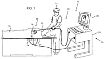
- Fig. 1 is a schematic illustration of an invasive medical procedure using a two wire transmission system 10
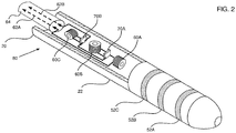
- Fig. 2 is a schematic illustration of a distal end of a catheter used in the procedure, according to embodiments.
- system 10 is assumed to be incorporated into an apparatus 12 used for an invasive medical procedure, performed by a medical professional 14, on a heart 16 of a human patient 18.
- apparatus 12 comprises magnetic transmitters 24, typically located beneath and external to the patient, in the vicinity of heart 16. Transmitters 24 are powered and controlled by a processor 26, which is located in an operating console 28 of apparatus 12.
- the Carto ® system produced by Biosense Webster, of Diamond Bar, CA, uses such a tracking method.
- signals generated within distal end 22, in response to the magnetic fields from the transmitters, are transferred back via catheter 20 to processor 26.
- the processor analyzes the received signals to determine a location and an orientation of the distal end, and may present the results on a screen 30 attached to the console.
- the results are typically presented by incorporating an icon representing the distal end into a map of the heart.
- signals generated within the distal end may also be transferred back via catheter 20, and results from analysis of the signals may be presented on screen 30.
- the results derived from these signals typically include numerical displays, and/or graphs representative of characteristics of the heart.
- Fig. 2 schematically shows elements of distal end 22.
- the distal end typically comprises one or more sensing elements used to measure characteristics of the part of heart 16 wherein distal end 22 is located.
- Such sensing elements may comprise, for example, a sensor measuring a force or pressure applied by the distal end to the heart, a sensor measuring a temperature of the heart, and/or an electrode measuring an electropotential of the heart.
- U. S. Patent 8,357,152 to Govari , et al. describes a system having a sensor generating pressure-sensing signals in the distal end of a catheter.
- signals provided by the type of sensors described above may be conveyed to processor 26 in embodiments.
- distal end 22 is assumed to comprise three generally similar electrodes 50, electrodes 52A, 52B, and 52C, which may be used to measure heart electropotentials.
- electrodes 52A, 52B, and/or 52C may also be used to apply radio-frequency ablation power to the heart.
- the distal end comprises three generally similar coils 60, coils 60A, 60B, and 60C, which are arranged to have axes that are mutually perpendicular to each other.
- the figure shows the coils as having separated centers; however, the coils may be configured to have a common center in order to save space.
- the coils generate the signals that are received by processor 26 (and referred to above) in response to the magnetic fields from transmitters 24.
- the three coil signals are transferred back to processor 26 via a single pair of conductors 62, conductors 62A, 62B, as explained below.
- Conductors 62 are typically enclosed in a cable 64 which is incorporated into catheter 20.
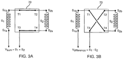
- Fig. 3A and Fig. 3B are schematic circuit diagrams respectively illustrating a first direct configuration of a generic cross-over switch 70, and a second crossed-over configuration of the switch, according to an embodiment of the present invention.
- Switch 70 may be in one of the two configurations, the characteristics of which are described below.
- Switch 70 comprises four isolated terminals T1, T2, T3, and T4. In the first configuration terminals T1 and T2 are connected together, and terminals T3 and T4 are connected together. In the second configuration terminals T1 and T4 are connected together, and terminals T3 and T2 are connected together.
- Switch 70 is connected to two signal sources, typically analog signal sources, respectively generating signals S 1 and S 2 .
- S 1 and S 2 A 1 e i ⁇ 1 ⁇ 1 ;
- S 2 A 2 e i ⁇ 2 ⁇ 2 where A 1 , A 2 are amplitudes, ⁇ 1 , ⁇ 2 are frequencies, and ⁇ 1 , ⁇ 1 are phases of the signals.
- the signal sources generating signals S 1 and S 2 are illustrated in Figs. 3A and 3B as coils, according to the invention.
- the entities generating signals S 1 and S 2 could in an example be any elements or combination of elements that give signals that may be represented by equation (1).
- Signal S 1 is developed between source terminals S 1a and S 1b ; similarly, signal S 2 is developed between source terminals S 2a and S 2b .
- the sources are connected to switch 70 as shown in the figures, i.e., source terminal S 1b is connected to switch terminal T1, source terminals S 2a and S 2b are respectively connected to switch terminals T2 and T4; and an output from the switched sources is taken between source terminal S 1a and switch terminal T3.
- cross-over switches 70 may be implemented by any suitable process known in the art. Such processes include, but are not limited to, producing the switches as microelectromechanical systems (MEMS) or as application specific integrated circuits (ASICs).
- MEMS microelectromechanical systems
- ASICs application specific integrated circuits
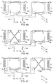
- Figs. 4A, 4B, and 4C are schematic circuit diagrams of different configurations of circuit 80 in distal end 22, according to an embodiment of the present apparatus.
- cross-over switches 70A and 70B are connected to coils 60C, 60B, and 60A, and the connections are as shown in Figs. 4A, 4B, and 4C .
- switch 70A is shown connected to coils 60A and 60B which have also been respectively labeled as sources generating signals S 1 and S 2 .
- the sources have terminals S 1a , S 1b , S 2a and S 2b .
- Switch 70B is also equivalent to generic switch 70 having a source corresponding to coil 60C and generating a signal S 3 connected to the switch.
- Coil 60C has source terminals S 3a , S 3b which are respectively connected to switch 70B terminals T4, T2.
- terminal T3 of switch 70A is connected to switch 70B terminal T1, and an output from the circuits is taken between source terminal S 1a and switch 70B terminal T3, which are respectively connected to conductors 62A and 62B.
- Processor 26 reconfigures circuit 80 in a cyclic manner, setting the configuration of the circuit as shown in Fig. 4A , then in Fig. 4B , then in Fig. 4C , and returning to the configuration of Fig. 4A .
- the periodicity of the cyclic reconfiguration is typically dependent on the characteristics of signals S 1 , S 2 , and S 3 .
- S 1 and S 2 are assumed to be of the form described above by equation (1);
- processor 26 may set a frequency of switching between the different configurations of circuit 80 to be of the order of 1 kHz, so that a different configuration occurs approximately each millisecond.
- Other suitable frequencies of switching between the configurations will be apparent to those having ordinary skill in the art, and all such frequencies are assumed to be within the scope of the present use.
- Fig. 4A illustrates a first configuration 82 of circuit 80, wherein switches 70A and 70B are both in the direct configuration.
- Fig. 4B illustrates a second configuration 84 of circuit 80, wherein switch 70B is in the direct configuration and switch 70A is in the crossed configuration.
- Fig. 4C illustrates a third configuration 86 of circuit 80, wherein switch 70B is in the crossed configuration and switch 70A is in the direct configuration.
- processor 26 receives values of V 1 , V 2 , and V 3 .
- Processor 26 may apply equations (8), (9), and (10), or a method equivalent to application of the equations, in order to derive values of S 1 , S 2 , and S 3 from measured values V 1 , V 2 , and V 3 .
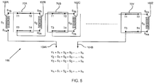
- FIG. 5 is a schematic circuit diagram of a sequence of multiple signal sources connected by cross-over switches, according to an embodiment of the present apparatus.
- a circuit 100 comprises a sequence of n signal sources 102 sources 102A, 102B, 102C, ..., 102Z, which respectively generate signals S 1 , S 2 , S 3 , ..., S n ; n is an integer equal to or greater than two.
- Sources 102 have respective pairs of terminals (S 1a , S 1b ), (S 2a , S 2b ), ... , and the signals S 1 , S 2 , S 3 , ..., S n generated across the terminals may be represented by equations similar to equations (1) and (4).
- Circuit 100 provides the signals it generates to a processor, herein assumed by way of example to be processor 26, via a pair of conductors 104A, 104B.
- Circuit 100 also comprises a sequence of (n - 1) cross-over switches 70, switches 70A, 70B, ..., 70Y. Except as described below, switches 70A, 70B and sources 102A, 102B, 102C are connected as described above for switches 70A, 70B and sources 60A, 60B, 60C ( Figs. 4A, 4B, 4C ).
- terminal S 1a is connected to conductor 104A, but terminal T3 of switch 70B is not connected to conductor 104B.
- terminal T3 of switch 70B is connected to a terminal T1 of a succeeding switch 70 (as switch 70A terminal T3 is connected to switch 70B terminal T1).
- the pattern of connecting terminal T3 of a given switch 70 to terminal T1 of a succeeding switch 70 continues until a final switch 70 in the sequence of switches is reached.
- Terminal T3 of the final switch illustrated as switch 70Y in the figure, is connected to conductor 104B.
- conductor 104A is connected to a first of the n sources 102, and conductor 104B is connected to the (n - 1) th switch 70.
- circuit 100 has been drawn with all switches 70 in the direct configuration.
- processor 26 In operating the circuit, processor 26 typically begins with the circuit in this configuration. The processor then toggles each of switches 70, between its direct and crossed configuration, in sequence, so that at any one time no more than one switch 70 is in the crossed configuration. When in its crossed configuration, the switch generates a local difference of the two signals connected to the switch. The toggling continues until the last switch in the sequence is reached. After the last switch has been toggled to its crossed configuration, it then reverts back to the direct configuration so that all switches 70 are again in the direct configuration shown in the figure. Processor 26 typically continues cycling the pattern of sequential toggling of the switches as long as signals S 1 , S 2 , S 3 , ..., S n are being measured.
- Outputs V 1 , V 2 , V 3 , ..., V n developed across conductors 104 and received by processor 26, during the sequential toggling described above, are given by the following set of equations (11), which comprise different linear combinations of signals S 1 , S 2 , S 3 , ..., S n .
- V 1 S 1 + S 2 + S 3 + S 4 + ⁇ + S n ⁇ 1 + S n
- V 2 S 1 ⁇ S 2 + S 3 + S 4 + ⁇ + S n ⁇ 1 + S n
- V 3 S 1 + S 2 ⁇ S 3 + S 4 + ⁇ + S n ⁇ 1 + S n
- Processor 26 applies equation (13), or uses an equivalent application, to derive values for signals S 1 , S 2 , S 3 , ..., S n from circuit outputs V 1 , V 2 , V 3 , ..., V n .
- circuits such as those described above enables processor 26 to sample multiple signals S 1 , S 2 , S 3 , ..., S n substantially simultaneously, using a single pair of conductors.
- signals from coils 60A, 60B, and 60C may be sampled simultaneously via conductors 62A and 62B.
- other signals such as those generated by electrodes 52, and/or those generated by sensors that may be incorporated into the distal end, such as the pressure sensor described in the above-referenced U. S. Patent 8,357,152 , may also be sampled via conductors 62A and 62B.
Description
- The present invention relates generally to signal transmission using conductors, and specifically to transmitting multiple signals over a minimal number of conductors.
- In many fields, a relatively large number of measurements may need to be made simultaneously, and the measurements may need to be transferred from the place of measurement to a distant location. Such transference may be difficult because of limited access between the place of measurement and the distant location. In minimally invasive medical surgery for example, the size of the access to a patient undergoing the surgery may be extremely limited, so that catheters or tools used for the surgery need to have diameters of the order of millimeters. Minimizing the number of conductors used to transfer the measurements enables the diameters of the catheters or tools to be reduced, with corresponding benefit to the patient.
-
US2013154867 (A1 ) discloses an A/D converter having high accuracy and high throughput irrespective of characteristic variations of analog circuits. The A/D converter includes a voltage-to-time converter configured to synchronize with a sampling clock signal and convert an input analog voltage to a time difference between two signals, and a plurality of time-to-digital converters each configured to convert the time difference between the two signals to a digital value. The plurality of time-to-digital converters operate in an interleaved manner. -
US6304769 (B1 ) discloses a magnetically directable guidance system useful in, for example, medical magnetic resonance imaging, as well as methods of directing the traverse of a device directable by the remote guidance system to a remote destination. A directable device and methods of use thereof are also disclosed. In one embodiment, the device is a catheter directable using a magnetic resonance imaging system. In another embodiment, the method includes interventional radiological diagnostic and therapeutic procedures. The documentUS 2008/2055551 A1 discloses an apparatus comprising signal sources in the form of antennae and further comprising two cross-over switches and a processor. - The present invention provides an apparatus as claimed in
claim 1 and a method as claimed in claim 4. Preferred embodiments are provided in the dependent claims. - The present disclosure will be more fully understood from the following detailed description of the embodiments thereof, taken together with the drawings, in which:
-
-
Fig. 1 is a schematic illustration of an invasive medical procedure using a two wire transmission system, according to an embodiment; -
Fig. 2 is a schematic illustration of a distal end of a catheter used in the procedure, according to an embodiment; -
Fig. 3A and Fig. 3B are schematic circuit diagrams illustrating a cross-over switch, according to an embodiment; -
Figs. 4A, 4B, and 4C are schematic circuit diagrams of different configurations of a circuit in the distal end of the catheter ofFig. 2 , according to an embodiment of the present invention; and -
Fig. 5 is a schematic circuit diagram of a sequence of multiple signal sources connected by cross-over switches, according to an embodiment of the present invention. - An embodiment provides a method for transferring multiple signals, typically analog signals, using a minimal number of conductors. Typically, only a single pair of conductors are required to transfer the multiple signals.
- In the case where the multiple signals comprise two signals from two signal sources, a cross-over switch having two configurations is connected between the two sources. In a direct configuration the switch generates a sum of the first and second signals; and in a crossed configuration the switch generates a difference between the first and second signals. The sum and the difference are conveyed to a processor, typically via a single pair of conductors and the processor recovers the two signals by analysis of the received sum and difference.
- In the case where the multiple signals comprise more than two signals from a corresponding number of signal sources, more cross-over switches are used. In general, for n signal sources (n a positive integer) (n - 1) cross-over switches are connected between the n sources. Typically, the configuration of the switches is altered in sequence, so that at any one time no more than one of the switches is in the crossed configuration, providing a local difference between the two signals connected to the switch. For each configuration of the switches a different linear combination of the signals is generated, each linear combination comprising a signal sum with at most one signal difference.
- The different linear combinations may be conveyed to the processor via a single pair of conductors, and the processor may recover each of the n signals by analysis of the linear combinations.
- Embodiments enable multiple signals to be sampled substantially simultaneously, and the signals may be transferred for subsequent recovery by a processor using a single pair of conductors. Once recovered, the processor has all of the signals available at all times, in contrast to a time multiplexing system of signal transfer, where the signals are available sequentially.
- In the following description, like elements in the drawings are identified by like numerals, and the like elements are differentiated as necessary by appending a letter to the identifying numeral.
-
Fig. 1 is a schematic illustration of an invasive medical procedure using a twowire transmission system 10, andFig. 2 is a schematic illustration of a distal end of a catheter used in the procedure, according to embodiments. By way of example,system 10 is assumed to be incorporated into anapparatus 12 used for an invasive medical procedure, performed by amedical professional 14, on aheart 16 of ahuman patient 18. - To perform the procedure, professional 14 inserts a
catheter 20 into the patient, so that adistal end 22 of the catheter enters the heart of the patient. In order to track the distal end while it is in the patient's heart,apparatus 12 comprisesmagnetic transmitters 24, typically located beneath and external to the patient, in the vicinity ofheart 16.Transmitters 24 are powered and controlled by aprocessor 26, which is located in anoperating console 28 ofapparatus 12. The Carto® system produced by Biosense Webster, of Diamond Bar, CA, uses such a tracking method. - As explained in more detail below, signals generated within
distal end 22, in response to the magnetic fields from the transmitters, are transferred back viacatheter 20 toprocessor 26. The processor analyzes the received signals to determine a location and an orientation of the distal end, and may present the results on ascreen 30 attached to the console. The results are typically presented by incorporating an icon representing the distal end into a map of the heart. - Other signals generated within the distal end, examples of which are provided below, may also be transferred back via
catheter 20, and results from analysis of the signals may be presented onscreen 30. The results derived from these signals typically include numerical displays, and/or graphs representative of characteristics of the heart. -
Fig. 2 schematically shows elements ofdistal end 22. The distal end typically comprises one or more sensing elements used to measure characteristics of the part ofheart 16 whereindistal end 22 is located. Such sensing elements may comprise, for example, a sensor measuring a force or pressure applied by the distal end to the heart, a sensor measuring a temperature of the heart, and/or an electrode measuring an electropotential of the heart. For example,U. S. Patent 8,357,152 to Govari , et al., describes a system having a sensor generating pressure-sensing signals in the distal end of a catheter. As will be apparent from the following description, signals provided by the type of sensors described above may be conveyed toprocessor 26 in embodiments. - By way of example,
distal end 22 is assumed to comprise three generally similar electrodes 50,electrodes embodiments electrodes - For the measurements from the sensing elements, such as electrodes 50, to be useful, it is typically necessary to know a location and orientation of the distal end wherein the elements are located. In order to provide the location and orientation, the distal end comprises three generally similar coils 60,
coils transmitters 24. However, rather than each signal being transferred back to the processor via a respective pair of conductors for each coil 60, in embodiments the three coil signals are transferred back toprocessor 26 via a single pair of conductors 62,conductors cable 64 which is incorporated intocatheter 20. - In order to transfer the signals by the pair of conductors 62, coils 60 are connected to two
cross-over switches 70,switches circuit 80.Fig. 3A and Fig. 3B are schematic circuit diagrams respectively illustrating a first direct configuration of ageneric cross-over switch 70, and a second crossed-over configuration of the switch, according to an embodiment of the present invention.Switch 70 may be in one of the two configurations, the characteristics of which are described below.Switch 70 comprises four isolated terminals T1, T2, T3, and T4. In the first configuration terminals T1 and T2 are connected together, and terminals T3 and T4 are connected together. In the second configuration terminals T1 and T4 are connected together, and terminals T3 and T2 are connected together. -
Switch 70 is connected to two signal sources, typically analog signal sources, respectively generating signals S1 and S2. In general, expressions for S1 and S2 are given by equation (1):
- The signal sources generating signals S1 and S2 are illustrated in
Figs. 3A and 3B as coils, according to the invention. The entities generating signals S1 and S2 could in an example be any elements or combination of elements that give signals that may be represented by equation (1). - Signal S1 is developed between source terminals S1a and S1b; similarly, signal S2 is developed between source terminals S2a and S2b. The sources are connected to switch 70 as shown in the figures, i.e., source terminal S1b is connected to switch terminal T1, source terminals S2a and S2b are respectively connected to switch terminals T2 and T4; and an output from the switched sources is taken between source terminal S1a and switch terminal T3.
- In the first, direct, configuration of
switch 70, an output Vsum between terminals S1a and T3 is a sum of the two signals, i.e.,
- In the second, crossed, configuration of
switch 70, an output Vdifference between terminals S1a and T3 is a sum of the first signal with a reversed polarity of the second signal, corresponding to a difference of the two signals, i.e.,
- In embodiments of the present apparatus, cross-over switches 70 may be implemented by any suitable process known in the art. Such processes include, but are not limited to, producing the switches as microelectromechanical systems (MEMS) or as application specific integrated circuits (ASICs). The configuration of each
switch 70, i.e., if aspecific switch 70 is in its first direct configuration or in its second crossed configuration, is under control ofprocessor 26 which is able to toggle the switch between the two configurations. For simplicity control links to the switches from the processor, enabling the toggling, are not shown in the diagram. -
Figs. 4A, 4B, and 4C are schematic circuit diagrams of different configurations ofcircuit 80 indistal end 22, according to an embodiment of the present apparatus. As stated above,cross-over switches Figs. 4A, 4B, and 4C . To illustrate the equivalence ofswitch 70B with generic switch 70 (shown inFigs. 3A and 3B )switch 70A is shown connected tocoils Figs. 3A and 3B the sources have terminals S1a, S1b, S2a and S2b. -
Switch 70B is also equivalent togeneric switch 70 having a source corresponding tocoil 60C and generating a signal S3 connected to the switch.Coil 60C has source terminals S3a, S3b which are respectively connected to switch 70B terminals T4, T2. - However, in the circuits of
Figs. 4A, 4B, and 4C terminal T3 ofswitch 70A is connected to switch 70B terminal T1, and an output from the circuits is taken between source terminal S1a and switch 70B terminal T3, which are respectively connected toconductors -
Processor 26 reconfigurescircuit 80 in a cyclic manner, setting the configuration of the circuit as shown inFig. 4A , then inFig. 4B , then inFig. 4C , and returning to the configuration ofFig. 4A . The periodicity of the cyclic reconfiguration is typically dependent on the characteristics of signals S1, S2, and S3. S1 and S2 are assumed to be of the form described above by equation (1); signal S3 is assumed to be of a similar character, and to have an equation of the form:
- For example, if the frequencies ω1, ω2, ω3 of the signals are of the order of 10 kHz, then
processor 26 may set a frequency of switching between the different configurations ofcircuit 80 to be of the order of 1 kHz, so that a different configuration occurs approximately each millisecond. Other suitable frequencies of switching between the configurations will be apparent to those having ordinary skill in the art, and all such frequencies are assumed to be within the scope of the present use. -
Fig. 4A illustrates afirst configuration 82 ofcircuit 80, wherein switches 70A and 70B are both in the direct configuration. In this case an output from conductors 62 is:
-
Fig. 4B illustrates asecond configuration 84 ofcircuit 80, whereinswitch 70B is in the direct configuration andswitch 70A is in the crossed configuration. In this case an output from conductors 62 is :
-
Fig. 4C illustrates athird configuration 86 ofcircuit 80, whereinswitch 70B is in the crossed configuration andswitch 70A is in the direct configuration. In this case an output from conductors 62 is :
- While switching between the three configurations of
circuit 80 described above,processor 26 receives values of V1, V2, and V3. By inspection of equations (5), (6), and (7), the following expressions for S1, S2, and S3 may be derived:


-
Processor 26 may apply equations (8), (9), and (10), or a method equivalent to application of the equations, in order to derive values of S1, S2, and S3 from measured values V1, V2, and V3. - The examples described above with reference to
Figs. 2 ,3A ,3B ,4A, 4B, and 4C illustrate circuits having one cross-over switch with two signal sources connected to the switch, and two cross-over switches with three signal sources connected to the switches. However, these are particular examples, and embodiments of the present apparatus include circuits having n signal sources, with (n - 1) cross-over switches connected between the sources, where n is any integer greater than one. -
Fig. 5 is a schematic circuit diagram of a sequence of multiple signal sources connected by cross-over switches, according to an embodiment of the present apparatus. Acircuit 100 comprises a sequence of n signal sources 102sources Circuit 100 provides the signals it generates to a processor, herein assumed by way of example to beprocessor 26, via a pair ofconductors -
Circuit 100 also comprises a sequence of (n - 1) cross-over switches 70, switches 70A, 70B, ..., 70Y. Except as described below, switches 70A, 70B andsources switches sources Figs. 4A, 4B, 4C ). Incircuit 100 terminal S1a is connected toconductor 104A, but terminal T3 ofswitch 70B is not connected toconductor 104B. - Rather, terminal T3 of
switch 70B is connected to a terminal T1 of a succeeding switch 70 (asswitch 70A terminal T3 is connected to switch 70B terminal T1). The pattern of connecting terminal T3 of a givenswitch 70 to terminal T1 of a succeedingswitch 70 continues until afinal switch 70 in the sequence of switches is reached. Terminal T3 of the final switch, illustrated asswitch 70Y in the figure, is connected toconductor 104B. Thusconductor 104A is connected to a first of the n sources 102, andconductor 104B is connected to the (n - 1)thswitch 70. - For simplicity,
circuit 100 has been drawn with allswitches 70 in the direct configuration. In operating the circuit,processor 26 typically begins with the circuit in this configuration. The processor then toggles each of switches 70, between its direct and crossed configuration, in sequence, so that at any one time no more than oneswitch 70 is in the crossed configuration. When in its crossed configuration, the switch generates a local difference of the two signals connected to the switch. The toggling continues until the last switch in the sequence is reached. After the last switch has been toggled to its crossed configuration, it then reverts back to the direct configuration so that all switches 70 are again in the direct configuration shown in the figure.Processor 26 typically continues cycling the pattern of sequential toggling of the switches as long as signals S1, S2, S3, ..., Sn are being measured. - Outputs V1, V2, V3, ..., Vn developed across conductors 104 and received by
processor 26, during the sequential toggling described above, are given by the following set of equations (11), which comprise different linear combinations of signals S1, S2, S3, ..., Sn.
- From inspection of equations (11), it is apparent that the coefficient of each of the signal terms S1, S2, S3, ..., Sn in each of the equations is +1 or -1. It is also apparent that in each of the equations there is at most one local difference between any two terms, and that relations between all the remaining terms are sums.
- Equations (11) may be written in matrix form:


matrix 
- From equation (12) an expression for signals S1, S2, S3, ..., Sn, is given by:

-
Processor 26 applies equation (13), or uses an equivalent application, to derive values for signals S1, S2, S3, ..., Sn from circuit outputs V1, V2, V3, ..., Vn. - Using circuits such as those described above enables
processor 26 to sample multiple signals S1, S2, S3, ..., Sn substantially simultaneously, using a single pair of conductors. Thus, returning toFig. 2 , signals fromcoils conductors electrodes 52, and/or those generated by sensors that may be incorporated into the distal end, such as the pressure sensor described in the above-referencedU. S. Patent 8,357,152 , may also be sampled viaconductors - It will be appreciated that the embodiments described above are cited by way of example, and that the present apparatus is not limited to what has been particularly shown and described hereinabove. The present invention is defined by the claims.
Claims (7)
- Apparatus, comprising:a first signal source configured to generate a first signal (S1), a second signal source configured to generate a second signal (S2), and a third signal source configured to generate a third signal (S3);a pair of conductors and a processor;a first (70A) and a second (70B) cross-over switch, each comprising four isolated terminals (T1, T2, T3, T4) and configured to be switchable between a first direct configuration in which a first terminal (T1) is connected to a second terminal (T2) and a third terminal (T3) is connected to a fourth terminal (T4), and a second crossed configuration in which the first terminal (T1) is connected to the fourth terminal (T4) and the second terminal (T2) is connected to the third terminal (T3);characterized in that the first, second and third signal sources comprise three generally similar coils (60A, 60B, 60C) which are arranged to have axes that are mutually perpendicular to each other, in that
the first cross-over switch (70A) is connected between the first and second signal sources such that the first source is connected between the first terminal (T1) and a first output, the second source is connected across the second and fourth terminals;in that the second cross-over switch (70B) is connected between the first cross-over switch (70A) and the third source such that the first terminal (T1) of the second cross-over switch is connected to the third terminal (T3) of the first cross-over switch (70A), the third source is connected across the second (T2) and fourth (T4) terminals of the second cross-over switch (70B), and the third terminal (T3) of the second cross-over switch (70B) provides a second output;in that the conductors are respectively connected to the first and second outputs and are configured to convey therefrom signals output by the cross-over switches to the processor; andin that the processor is configured to toggle the cross-over switches cyclically between:(a) a first configuration in which the first and second cross-over switches (70A, 70B) are both in the direct configuration, wherein an output (V1) across the two outputs represents the following combination of signals: V1=S1+S2+S3;(b) a second configuration in which the first cross-over switch (70A) is in the crossed configuration and the second cross-over switch (70B) is in the direct configuration, wherein an output (V2) across the two outputs represents the following combination of signals:V2=S1-S2+S3; and(c) a third configuration in which the first cross-over switch (70A) is in the direct configuration and the second cross-over switch (70B) is in the crossed configuration, wherein an output (V3) across the two outputs represents the following combination of signals:V3=S1+S2-S3;wherein the processor is further configured to receive the outputs (V1, V2, V3) and through application of the equations S1=(V2+V3)/2, S2=(V1-V2)/2 and S3=(V1-V3)/2 to recover the first (S1), second (S2) and third (S3) signals therefrom. - The apparatus according to claim 1, and comprising a distal end of a catheter, configured for insertion into a human patient, wherein the first signal source, the second signal source, the third signal source, the first cross-over switch and the second cross-over switch are incorporated.
- The apparatus according to claim 2, wherein the first, second and third signal sources respectively comprise first, second and third coils configured to generate respectively the first, second and third signals in response to magnetic fields generated external to the distal end, and wherein the processor is configured to determine an indication of a location and an orientation of the distal end in response to the first, second and third signals.
- A method, comprising:generating, using a first signal source, a second signal source and a third signal source, first (S1), second (S2) and third (S3) signals;providing a first (70A) and a second (70B) cross-over switch, each comprising four isolated terminals (T1, T2, T3, T4) and configured to be switchable between a first direct configuration in which a first terminal (T1) is connected to a second terminal (T2) and a third terminal (T3) is connected to a fourth terminal (T4), and a second crossed configuration in which the first terminal (T1) is connected to the fourth terminal (T4) and the second terminal (T2) is connected to the third terminal (T3);connecting the first cross-over switch (70A) between the first and second signal sources such that the first source is connected between the first terminal (T1) and a first output, and the second source is connected across the second and fourth terminals;connecting the second cross-over switch (70B) between the first cross-over switch (70A) and the third source such that the first terminal (T1) of the second cross-over switch is connected to the third terminal (T3) of the first cross-over switch (70A), the third source is connected across the second (T2) and fourth (T4) terminals of the second cross-over switch (70B), and the third terminal (T3) of the second cross-over switch (70B) provides a second output;conveying, via a pair of conductors, respectively connected to the first and second outputs, signals output by the cross-over switches to a processor; andin the processor, toggling the cross-over switches cyclically between:(a) a first configuration in which the first and second cross-over switches (70A, 70B) are both in the direct configuration, wherein an output (V1) across the two outputs represents the following combination of signals: V1=S1+S2+S3;(b) a second configuration in which the first cross-over switch (70A) is in the crossed configuration and the second cross-over switch (70B) is in the direct configuration, wherein an output (V2) across the two outputs represents the following combination of signals:V2=S1-S2+S3; and(c) a third configuration in which the first cross-over switch (70A) is in the direct configuration and the second cross-over switch (70B) is in the crossed configuration, wherein an output (V3) across the two outputs represents the following combination of signals:V3=S1+S2-S3; andsuch that the outputs (V1, V2, V3) are received in the processor, and applying the equations S1=(V2+V3)/2, S2=(V1-V2)/2 and S3=(V1-V3)/2 to the received outputs (V1, V2, V3) so as to recover the first (S1), second (S2) and third (S3) signals therefrom.
- The apparatus according to claim 1 or the method according to claim 4, wherein the first and the second signals comprise analog signals.
- The method according to claim 4, and comprising providing a distal end of a catheter configured for insertion into a human, but positioned outside of the human and incorporating the first, second and third signal sources, and the first and second cross-over switches into the distal end.
- The method according to claim 6, wherein the first, second and third signal sources respectively comprise first, second and third coils configured to generate respectively the first, second and third signals in response to magnetic fields generated external to the distal end, and comprising the processor determining an indication of a location and an orientation of the distal end in response to the first, second and third signals.
Applications Claiming Priority (1)
| Application Number | Priority Date | Filing Date | Title |
|---|---|---|---|
| US13/946,031 US9425860B2 (en) | 2013-07-19 | 2013-07-19 | Two wire signal transmission |
Publications (2)
| Publication Number | Publication Date |
|---|---|
| EP2829227A1 EP2829227A1 (en) | 2015-01-28 |
| EP2829227B1 true EP2829227B1 (en) | 2022-01-12 |
Family
ID=51266093
Family Applications (1)
| Application Number | Title | Priority Date | Filing Date |
|---|---|---|---|
| EP14177839.9A Active EP2829227B1 (en) | 2013-07-19 | 2014-07-21 | Cross-over switch for providing linear combinations of signals and a processor for recovering the original signals |
Country Status (7)
| Country | Link |
|---|---|
| US (1) | US9425860B2 (en) |
| EP (1) | EP2829227B1 (en) |
| JP (1) | JP6644459B2 (en) |
| CN (1) | CN104299396B (en) |
| AU (1) | AU2014203840B2 (en) |
| CA (1) | CA2856853A1 (en) |
| IL (1) | IL233417B (en) |
Families Citing this family (3)
| Publication number | Priority date | Publication date | Assignee | Title |
|---|---|---|---|---|
| CN105844092A (en) * | 2016-03-21 | 2016-08-10 | 中国人民解放军国防科学技术大学 | Prediction and assessment method for two-lead transmission line terminal response |
| US20180264229A1 (en) * | 2017-03-16 | 2018-09-20 | Weinberg Medical Physics, Inc. | Method and apparatus for rapid assessment and treatment of traumatic brain injury |
| EP3530178A1 (en) * | 2018-02-27 | 2019-08-28 | Koninklijke Philips N.V. | A sensor arrangement for mounting on a guidewire or catheter |
Family Cites Families (13)
| Publication number | Priority date | Publication date | Assignee | Title |
|---|---|---|---|---|
| DE69726415T2 (en) * | 1996-02-15 | 2004-09-16 | Biosense, Inc., Miami | INDEPENDENTLY ADJUSTABLE CONVERTERS FOR LOCATION SYSTEMS |
| US6304769B1 (en) | 1997-10-16 | 2001-10-16 | The Regents Of The University Of California | Magnetically directable remote guidance systems, and methods of use thereof |
| JP3342001B2 (en) * | 1998-10-13 | 2002-11-05 | 日本ビクター株式会社 | Recording medium, audio decoding device |
| US7355716B2 (en) * | 2002-01-24 | 2008-04-08 | The General Hospital Corporation | Apparatus and method for ranging and noise reduction of low coherence interferometry LCI and optical coherence tomography OCT signals by parallel detection of spectral bands |
| EP1685366B1 (en) * | 2003-10-27 | 2011-06-15 | The General Hospital Corporation | Method and apparatus for performing optical imaging using frequency-domain interferometry |
| US9623208B2 (en) | 2004-01-12 | 2017-04-18 | Varian Medical Systems, Inc. | Instruments with location markers and methods for tracking instruments through anatomical passageways |
| US8945095B2 (en) * | 2005-03-30 | 2015-02-03 | Intuitive Surgical Operations, Inc. | Force and torque sensing for surgical instruments |
| US7869535B2 (en) | 2007-02-28 | 2011-01-11 | Magnolia Broadband Inc. | Method, system and apparatus for phase control of transmit diversity signals |
| US8357152B2 (en) | 2007-10-08 | 2013-01-22 | Biosense Webster (Israel), Ltd. | Catheter with pressure sensing |
| US9089292B2 (en) * | 2010-03-26 | 2015-07-28 | Medtronic Minimed, Inc. | Calibration of glucose monitoring sensor and/or insulin delivery system |
| JP5383610B2 (en) | 2010-08-17 | 2014-01-08 | パナソニック株式会社 | A / D converter |
| US9180043B2 (en) * | 2010-11-15 | 2015-11-10 | Focal Cool, Llc | Apparatus for treatment of reperfusion injury |
| US8942644B2 (en) | 2011-11-11 | 2015-01-27 | Apple Inc. | Systems and methods for protecting microelectromechanical systems switches from radio-frequency signals using switching circuitry |
-
2013
- 2013-07-19 US US13/946,031 patent/US9425860B2/en active Active
-
2014
- 2014-06-26 IL IL233417A patent/IL233417B/en active IP Right Grant
- 2014-07-11 CA CA2856853A patent/CA2856853A1/en not_active Abandoned
- 2014-07-14 AU AU2014203840A patent/AU2014203840B2/en active Active
- 2014-07-18 CN CN201410344626.4A patent/CN104299396B/en active Active
- 2014-07-18 JP JP2014147572A patent/JP6644459B2/en active Active
- 2014-07-21 EP EP14177839.9A patent/EP2829227B1/en active Active
Also Published As
| Publication number | Publication date |
|---|---|
| JP6644459B2 (en) | 2020-02-12 |
| US20150023374A1 (en) | 2015-01-22 |
| US9425860B2 (en) | 2016-08-23 |
| CA2856853A1 (en) | 2015-01-19 |
| CN104299396B (en) | 2019-04-16 |
| EP2829227A1 (en) | 2015-01-28 |
| AU2014203840A1 (en) | 2015-02-05 |
| AU2014203840B2 (en) | 2019-06-13 |
| IL233417B (en) | 2019-07-31 |
| JP2015020073A (en) | 2015-02-02 |
| CN104299396A (en) | 2015-01-21 |
Similar Documents
| Publication | Publication Date | Title |
|---|---|---|
| EP2829227B1 (en) | Cross-over switch for providing linear combinations of signals and a processor for recovering the original signals | |
| US4858617A (en) | Cardiac probe enabling use of personal computer for monitoring heart activity or the like | |
| CN103376172B (en) | Six-dimensional force sense sensor for minimally invasive surgical operation robot | |
| US20060009691A1 (en) | Method, medium, and apparatus measuring biological signals using multi-electrode module, with a lead search | |
| EP2110639A1 (en) | Spatial information detecting system, its detecting method, and spatial information detecting device | |
| JP2005279278A (en) | Apparatus and method for simultaneously measuring bio signal and computer readable recording medium | |
| EP2666411B1 (en) | Position sensing using electric dipole fields | |
| EP3695781A1 (en) | Bioinformation measurement device and bioinformation measurement system | |
| EP3372148A1 (en) | Physiological measurement device with common mode interference suppression | |
| US20190150756A1 (en) | Signal synchronization device, as well as stethoscope, auscultation information output system and symptom diagnosis system capable of signal synchronization | |
| US9615760B2 (en) | Multiple bipolar sampling | |
| JPH09122098A (en) | Movement information detector for tip part of endoscope probe | |
| CN219594618U (en) | Electrocardiogram apparatus and magnetic resonance apparatus configured for use in conjunction with magnetic resonance apparatus | |
| WO2004110269A1 (en) | Sensor for magnetoencephalography meter and supermultichannel magnetoencephalography meter system using the same | |
| Miao et al. | A new symmetric semi-parallel electrical impedance tomography (EIT) system-I: The design | |
| CN111227848B (en) | Skin resistance measuring device based on multiple channels | |
| CN114431863A (en) | System for measuring electrode contact impedance and impedance measuring method | |
| EP3586738A1 (en) | Improving signal quality in a multiplexing system by actively disconnecting unused connections | |
| KR102237213B1 (en) | Apparatus and Method for Concurrent Bio-impedance Measurement and Time Synchronization on Different Body Sites | |
| Orsolini et al. | Wireless Electrocardiography and Impedance Cardiography Devices Using a Network Time Protocol for Synchronized Data | |
| CN206818821U (en) | For detecting short-circuit system and device in wiring | |
| KR20050063232A (en) | Realtime multiplexing data aquisition system and method for multichannel bio-magnetic signal | |
| JPH1147106A (en) | Electrode for measuring biological signal and electrode aid for measuring biological signal | |
| RU2088154C1 (en) | Device for carrying out physiological studies | |
| CN114795274A (en) | Heart sound picture detection system |
Legal Events
| Date | Code | Title | Description |
|---|---|---|---|
| 17P | Request for examination filed |
Effective date: 20140721 |
|
| AK | Designated contracting states |
Kind code of ref document: A1 Designated state(s): AL AT BE BG CH CY CZ DE DK EE ES FI FR GB GR HR HU IE IS IT LI LT LU LV MC MK MT NL NO PL PT RO RS SE SI SK SM TR |
|
| AX | Request for extension of the european patent |
Extension state: BA ME |
|
| PUAI | Public reference made under article 153(3) epc to a published international application that has entered the european phase |
Free format text: ORIGINAL CODE: 0009012 |
|
| R17P | Request for examination filed (corrected) |
Effective date: 20150727 |
|
| RBV | Designated contracting states (corrected) |
Designated state(s): AL AT BE BG CH CY CZ DE DK EE ES FI FR GB GR HR HU IE IS IT LI LT LU LV MC MK MT NL NO PL PT RO RS SE SI SK SM TR |
|
| STAA | Information on the status of an ep patent application or granted ep patent |
Free format text: STATUS: EXAMINATION IS IN PROGRESS |
|
| 17Q | First examination report despatched |
Effective date: 20200224 |
|
| STAA | Information on the status of an ep patent application or granted ep patent |
Free format text: STATUS: EXAMINATION IS IN PROGRESS |
|
| REG | Reference to a national code |
Ref country code: DE Ref legal event code: R079 Ref document number: 602014082133 Country of ref document: DE Free format text: PREVIOUS MAIN CLASS: A61B0005060000 Ipc: A61B0005000000 |
|
| RIC1 | Information provided on ipc code assigned before grant |
Ipc: A61B 5/06 20060101ALI20201130BHEP Ipc: H04Q 3/00 20060101ALI20201130BHEP Ipc: H04B 3/60 20060101ALI20201130BHEP Ipc: A61B 5/00 20060101AFI20201130BHEP |
|
| GRAP | Despatch of communication of intention to grant a patent |
Free format text: ORIGINAL CODE: EPIDOSNIGR1 |
|
| STAA | Information on the status of an ep patent application or granted ep patent |
Free format text: STATUS: GRANT OF PATENT IS INTENDED |
|
| INTG | Intention to grant announced |
Effective date: 20210203 |
|
| RAP1 | Party data changed (applicant data changed or rights of an application transferred) |
Owner name: BIOSENSE WEBSTER (ISRAEL) LTD. |
|
| GRAJ | Information related to disapproval of communication of intention to grant by the applicant or resumption of examination proceedings by the epo deleted |
Free format text: ORIGINAL CODE: EPIDOSDIGR1 |
|
| STAA | Information on the status of an ep patent application or granted ep patent |
Free format text: STATUS: EXAMINATION IS IN PROGRESS |
|
| INTC | Intention to grant announced (deleted) | ||
| GRAP | Despatch of communication of intention to grant a patent |
Free format text: ORIGINAL CODE: EPIDOSNIGR1 |
|
| STAA | Information on the status of an ep patent application or granted ep patent |
Free format text: STATUS: GRANT OF PATENT IS INTENDED |
|
| INTG | Intention to grant announced |
Effective date: 20210729 |
|
| GRAS | Grant fee paid |
Free format text: ORIGINAL CODE: EPIDOSNIGR3 |
|
| GRAA | (expected) grant |
Free format text: ORIGINAL CODE: 0009210 |
|
| STAA | Information on the status of an ep patent application or granted ep patent |
Free format text: STATUS: THE PATENT HAS BEEN GRANTED |
|
| AK | Designated contracting states |
Kind code of ref document: B1 Designated state(s): AL AT BE BG CH CY CZ DE DK EE ES FI FR GB GR HR HU IE IS IT LI LT LU LV MC MK MT NL NO PL PT RO RS SE SI SK SM TR |
|
| REG | Reference to a national code |
Ref country code: GB Ref legal event code: FG4D |
|
| REG | Reference to a national code |
Ref country code: CH Ref legal event code: EP |
|
| REG | Reference to a national code |
Ref country code: DE Ref legal event code: R096 Ref document number: 602014082133 Country of ref document: DE |
|
| REG | Reference to a national code |
Ref country code: IE Ref legal event code: FG4D |
|
| REG | Reference to a national code |
Ref country code: AT Ref legal event code: REF Ref document number: 1461849 Country of ref document: AT Kind code of ref document: T Effective date: 20220215 |
|
| REG | Reference to a national code |
Ref country code: NL Ref legal event code: FP |
|
| REG | Reference to a national code |
Ref country code: LT Ref legal event code: MG9D |
|
| RAP4 | Party data changed (patent owner data changed or rights of a patent transferred) |
Owner name: BIOSENSE WEBSTER (ISRAEL) LTD. |
|
| REG | Reference to a national code |
Ref country code: AT Ref legal event code: MK05 Ref document number: 1461849 Country of ref document: AT Kind code of ref document: T Effective date: 20220112 |
|
| PG25 | Lapsed in a contracting state [announced via postgrant information from national office to epo] |
Ref country code: SE Free format text: LAPSE BECAUSE OF FAILURE TO SUBMIT A TRANSLATION OF THE DESCRIPTION OR TO PAY THE FEE WITHIN THE PRESCRIBED TIME-LIMIT Effective date: 20220112 Ref country code: RS Free format text: LAPSE BECAUSE OF FAILURE TO SUBMIT A TRANSLATION OF THE DESCRIPTION OR TO PAY THE FEE WITHIN THE PRESCRIBED TIME-LIMIT Effective date: 20220112 Ref country code: PT Free format text: LAPSE BECAUSE OF FAILURE TO SUBMIT A TRANSLATION OF THE DESCRIPTION OR TO PAY THE FEE WITHIN THE PRESCRIBED TIME-LIMIT Effective date: 20220512 Ref country code: NO Free format text: LAPSE BECAUSE OF FAILURE TO SUBMIT A TRANSLATION OF THE DESCRIPTION OR TO PAY THE FEE WITHIN THE PRESCRIBED TIME-LIMIT Effective date: 20220412 Ref country code: LT Free format text: LAPSE BECAUSE OF FAILURE TO SUBMIT A TRANSLATION OF THE DESCRIPTION OR TO PAY THE FEE WITHIN THE PRESCRIBED TIME-LIMIT Effective date: 20220112 Ref country code: HR Free format text: LAPSE BECAUSE OF FAILURE TO SUBMIT A TRANSLATION OF THE DESCRIPTION OR TO PAY THE FEE WITHIN THE PRESCRIBED TIME-LIMIT Effective date: 20220112 Ref country code: ES Free format text: LAPSE BECAUSE OF FAILURE TO SUBMIT A TRANSLATION OF THE DESCRIPTION OR TO PAY THE FEE WITHIN THE PRESCRIBED TIME-LIMIT Effective date: 20220112 Ref country code: BG Free format text: LAPSE BECAUSE OF FAILURE TO SUBMIT A TRANSLATION OF THE DESCRIPTION OR TO PAY THE FEE WITHIN THE PRESCRIBED TIME-LIMIT Effective date: 20220412 |
|
| PGFP | Annual fee paid to national office [announced via postgrant information from national office to epo] |
Ref country code: IT Payment date: 20220613 Year of fee payment: 9 |
|
| PG25 | Lapsed in a contracting state [announced via postgrant information from national office to epo] |
Ref country code: PL Free format text: LAPSE BECAUSE OF FAILURE TO SUBMIT A TRANSLATION OF THE DESCRIPTION OR TO PAY THE FEE WITHIN THE PRESCRIBED TIME-LIMIT Effective date: 20220112 Ref country code: LV Free format text: LAPSE BECAUSE OF FAILURE TO SUBMIT A TRANSLATION OF THE DESCRIPTION OR TO PAY THE FEE WITHIN THE PRESCRIBED TIME-LIMIT Effective date: 20220112 Ref country code: GR Free format text: LAPSE BECAUSE OF FAILURE TO SUBMIT A TRANSLATION OF THE DESCRIPTION OR TO PAY THE FEE WITHIN THE PRESCRIBED TIME-LIMIT Effective date: 20220413 Ref country code: FI Free format text: LAPSE BECAUSE OF FAILURE TO SUBMIT A TRANSLATION OF THE DESCRIPTION OR TO PAY THE FEE WITHIN THE PRESCRIBED TIME-LIMIT Effective date: 20220112 Ref country code: AT Free format text: LAPSE BECAUSE OF FAILURE TO SUBMIT A TRANSLATION OF THE DESCRIPTION OR TO PAY THE FEE WITHIN THE PRESCRIBED TIME-LIMIT Effective date: 20220112 |
|
| PG25 | Lapsed in a contracting state [announced via postgrant information from national office to epo] |
Ref country code: IS Free format text: LAPSE BECAUSE OF FAILURE TO SUBMIT A TRANSLATION OF THE DESCRIPTION OR TO PAY THE FEE WITHIN THE PRESCRIBED TIME-LIMIT Effective date: 20220512 |
|
| REG | Reference to a national code |
Ref country code: DE Ref legal event code: R097 Ref document number: 602014082133 Country of ref document: DE |
|
| PG25 | Lapsed in a contracting state [announced via postgrant information from national office to epo] |
Ref country code: SM Free format text: LAPSE BECAUSE OF FAILURE TO SUBMIT A TRANSLATION OF THE DESCRIPTION OR TO PAY THE FEE WITHIN THE PRESCRIBED TIME-LIMIT Effective date: 20220112 Ref country code: SK Free format text: LAPSE BECAUSE OF FAILURE TO SUBMIT A TRANSLATION OF THE DESCRIPTION OR TO PAY THE FEE WITHIN THE PRESCRIBED TIME-LIMIT Effective date: 20220112 Ref country code: RO Free format text: LAPSE BECAUSE OF FAILURE TO SUBMIT A TRANSLATION OF THE DESCRIPTION OR TO PAY THE FEE WITHIN THE PRESCRIBED TIME-LIMIT Effective date: 20220112 Ref country code: EE Free format text: LAPSE BECAUSE OF FAILURE TO SUBMIT A TRANSLATION OF THE DESCRIPTION OR TO PAY THE FEE WITHIN THE PRESCRIBED TIME-LIMIT Effective date: 20220112 Ref country code: DK Free format text: LAPSE BECAUSE OF FAILURE TO SUBMIT A TRANSLATION OF THE DESCRIPTION OR TO PAY THE FEE WITHIN THE PRESCRIBED TIME-LIMIT Effective date: 20220112 Ref country code: CZ Free format text: LAPSE BECAUSE OF FAILURE TO SUBMIT A TRANSLATION OF THE DESCRIPTION OR TO PAY THE FEE WITHIN THE PRESCRIBED TIME-LIMIT Effective date: 20220112 |
|
| PLBE | No opposition filed within time limit |
Free format text: ORIGINAL CODE: 0009261 |
|
| STAA | Information on the status of an ep patent application or granted ep patent |
Free format text: STATUS: NO OPPOSITION FILED WITHIN TIME LIMIT |
|
| PG25 | Lapsed in a contracting state [announced via postgrant information from national office to epo] |
Ref country code: AL Free format text: LAPSE BECAUSE OF FAILURE TO SUBMIT A TRANSLATION OF THE DESCRIPTION OR TO PAY THE FEE WITHIN THE PRESCRIBED TIME-LIMIT Effective date: 20220112 |
|
| 26N | No opposition filed |
Effective date: 20221013 |
|
| PG25 | Lapsed in a contracting state [announced via postgrant information from national office to epo] |
Ref country code: SI Free format text: LAPSE BECAUSE OF FAILURE TO SUBMIT A TRANSLATION OF THE DESCRIPTION OR TO PAY THE FEE WITHIN THE PRESCRIBED TIME-LIMIT Effective date: 20220112 Ref country code: MC Free format text: LAPSE BECAUSE OF FAILURE TO SUBMIT A TRANSLATION OF THE DESCRIPTION OR TO PAY THE FEE WITHIN THE PRESCRIBED TIME-LIMIT Effective date: 20220112 |
|
| REG | Reference to a national code |
Ref country code: CH Ref legal event code: PL |
|
| REG | Reference to a national code |
Ref country code: BE Ref legal event code: MM Effective date: 20220731 |
|
| PG25 | Lapsed in a contracting state [announced via postgrant information from national office to epo] |
Ref country code: LU Free format text: LAPSE BECAUSE OF NON-PAYMENT OF DUE FEES Effective date: 20220721 Ref country code: LI Free format text: LAPSE BECAUSE OF NON-PAYMENT OF DUE FEES Effective date: 20220731 Ref country code: CH Free format text: LAPSE BECAUSE OF NON-PAYMENT OF DUE FEES Effective date: 20220731 |
|
| PG25 | Lapsed in a contracting state [announced via postgrant information from national office to epo] |
Ref country code: BE Free format text: LAPSE BECAUSE OF NON-PAYMENT OF DUE FEES Effective date: 20220731 |
|
| PG25 | Lapsed in a contracting state [announced via postgrant information from national office to epo] |
Ref country code: IE Free format text: LAPSE BECAUSE OF NON-PAYMENT OF DUE FEES Effective date: 20220721 |
|
| PGFP | Annual fee paid to national office [announced via postgrant information from national office to epo] |
Ref country code: NL Payment date: 20230614 Year of fee payment: 10 Ref country code: FR Payment date: 20230620 Year of fee payment: 10 |
|
| PGFP | Annual fee paid to national office [announced via postgrant information from national office to epo] |
Ref country code: GB Payment date: 20230601 Year of fee payment: 10 |
|
| PGFP | Annual fee paid to national office [announced via postgrant information from national office to epo] |
Ref country code: DE Payment date: 20230531 Year of fee payment: 10 |
|
| PG25 | Lapsed in a contracting state [announced via postgrant information from national office to epo] |
Ref country code: HU Free format text: LAPSE BECAUSE OF FAILURE TO SUBMIT A TRANSLATION OF THE DESCRIPTION OR TO PAY THE FEE WITHIN THE PRESCRIBED TIME-LIMIT; INVALID AB INITIO Effective date: 20140721 |