EP2829201B1 - Système de présentation de récipient de produit au détail - Google Patents
Système de présentation de récipient de produit au détail Download PDFInfo
- Publication number
- EP2829201B1 EP2829201B1 EP14175187.5A EP14175187A EP2829201B1 EP 2829201 B1 EP2829201 B1 EP 2829201B1 EP 14175187 A EP14175187 A EP 14175187A EP 2829201 B1 EP2829201 B1 EP 2829201B1
- Authority
- EP
- European Patent Office
- Prior art keywords
- hand side
- lanes
- side rail
- channels
- spaced apart
- Prior art date
- Legal status (The legal status is an assumption and is not a legal conclusion. Google has not performed a legal analysis and makes no representation as to the accuracy of the status listed.)
- Active
Links
Images


Classifications
-
- A—HUMAN NECESSITIES
- A47—FURNITURE; DOMESTIC ARTICLES OR APPLIANCES; COFFEE MILLS; SPICE MILLS; SUCTION CLEANERS IN GENERAL
- A47F—SPECIAL FURNITURE, FITTINGS, OR ACCESSORIES FOR SHOPS, STOREHOUSES, BARS, RESTAURANTS OR THE LIKE; PAYING COUNTERS
- A47F1/00—Racks for dispensing merchandise; Containers for dispensing merchandise
- A47F1/04—Racks or containers with arrangements for dispensing articles, e.g. by means of gravity or springs
- A47F1/12—Racks or containers with arrangements for dispensing articles, e.g. by means of gravity or springs dispensing from the side of an approximately horizontal stack
Definitions
- This disclosure relates generally to the field of retail product display systems. More specifically, the disclosure relates to product displays in which generally cylindrical product containers are stored and displayed for sale.
- Retail product displays known in the art include display systems for beverage containers. Such displays may include both bottled beverage containers stored in a substantially vertical orientation and substantially cylindrical cans also stored substantially vertically. Both such types of containers may be stored in, for example, a refrigerated display case. Vertically oriented containers may be stored on a device that separates the product containers into laterally adjacent rows or "lanes", and urges the product containers forward using a spring loaded pusher or gravity.
- bottle containers are substantially taller than cans.
- using side by side devices such as the FLEXROLLER device may result in underutilized space in a refrigerated display case.
- One device known in the art for using the available vertical space more efficiently displays cylindrical containers such as cans disposed horizontally and uses gravity to urge the stored cans forward to the front of the device.
- Several of such devices may be vertically stacked to use the space in the refrigerated display case.
- Other devices may store product containers horizontally and have vertical stacking by having therein a serpentine track to enable vertical separation of rows of the containers.
- a merchandising system with T-shaped dividers is disclosed in US2006/0186066A1 .
- Adjustable and/or stackable display units are disclosed in US 5,806,690 , US 4,356,923 , US 4,228,903 , US RE 33515E , US 4,685,574 and US 5,366,099 .
- Each of the foregoing example devices is made for a particular height of cylindrical product container (can) and/or is made with a plurality of vertical rows of "lanes. "
- a retail product container display system includes at least one product storage lane.
- the at least one product storage lane comprising a left hand side rail and a right hand side rail and at least two connectors engaged with receptacles therefor on each of the left hand and right hand side rails.
- the receptacles are disposed at corresponding longitudinally spaced apart positions along each of the side rails.
- Each of the side rails comprises a vertical wall and a horizontal floor.
- a retail product container display system comprises:
- each of the at least two connectors comprises, on each side thereof, a deflectable locking tab having a detent bar on a surface thereof, and wherein the receptacles each include a plurality of laterally spaced apart slots configured to engage the detent bar of a respective end of one of the at least two connectors, whereby a width of the at least one product storage lane is adjustable.
- the receptacles are disposed on a bottom surface of the horizontal floor of each of the left hand and right hand side rails.
- the system further comprises a plurality longitudinally spaced apart channels formed on an outer surface of the side wall of each of the side rails, the channels each configured to receive a vertical support connector therein, whereby a plurality of lanes are vertically stackable.
- the plurality of longitudinally spaced apart channels are arranged to enable vertical assembly of a plurality of lanes, and wherein vertically adjacent lanes are interconnected by a support connector disposed in each selected ones of the spaced apart channels on each of the side rails.
- a longitudinal position of the channels on the left hand side wall is offset from a longitudinal position of the channels on the right hand side wall such that a lateral space between laterally placed adjacent lanes is settable to substantially zero.
- system further comprises support feet attachable to a bottom of each of the left hand side rail and the right hand side rail, the support feet providing the at least one lane with a selected tilt.
- system further comprises an end barrier disposed at a forward end of at least one of the left hand side rail and the right hand side rail.
- the end barrier is integrally formed with the at least one of the left hand side rail and the right hand side rail.
- each of the side rails comprises a forward stop and a forward end; and wherein each of the at least two connectors comprises, on each side thereof, a deflectable locking tab having a detent bar on a surface thereof, and wherein the receptacles each include a plurality of laterally spaced apart slots configured to engage the detent bar of a respective end of the one of the at least two connectors, whereby a width of the at least one storage lane is adjustable.
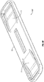
- FIG. 1 shows an example "lanes" 10 in oblique view.
- the lane 10 when assembled from components to be further explained below forms a single basic display unit of a product container display system according to the present disclosure.
- FIG. 1A shows support feet 12 that may be affixed, such as by clips, to the bottom of a lane 10 at its rearward end so as to tilt the lane 10 ( FIG. 1 ) forward.
- the support feet 12 may be used in instances where the device in which the system is used has a substantially horizontal bottom, whereby the forward tilt provided by the support feet 12 urges product containers (see FIG. 7 ) to a forward end of the lane 10.
- the lowermost lane 10 in a plurality of vertically assembled, stacked lanes will have the support feet 12 attached to the bottom thereof as shown in FIG. 1A .
- FIG. 2 shows two additional lanes 10, which may be substantially identical to the lane shown in FIG. 1 , along with a plurality of vertical support connectors 14 that may be disposed in receptacles (explained with reference to FIG. 3 ) on an exterior of the sides of each lane 10 so that a plurality of lanes 10 may be assembled vertically stacked to form the product display system.
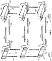
- FIG. 3 shows components of an example display system in exploded view.
- Each lane (10 in FIGS. 1 and 2 ) includes a left hand side rail 10A and a right hand side rail 10B.
- Each side rail 10A, 10B includes a substantially vertically extending wall 9 and a substantially horizontal floor 7.
- the side rails 10A, 10B may include connector receptacles 16 on a bottom surface of the floor 7 to provide an engagement feature for connectors 10C that adjustably connect the left hand side rail 10A to the right hand side rail 10B.
- the foregoing receptacles 16 and connectors 10C will be explained in more detail below.
- the wall 9, receptacles 16 and floor 7 may be molded or formed as a single, unitary component from any suitable material such as plastic.
- Each of the side rails 10A, 10B may have a corresponding forward end barrier 10D, 10E affixed to the forward end of the side rail.
- the end barriers 10D, 10E may be formed integrally with the corresponding side rail 10A, 10B or may be formed as separate components that can be affixed to the corresponding side rail using suitably shaped interlocking features (not shown in detail).
- the end barriers 10D, 10E provide a stop for product containers ( FIG. 7 ) stored on each lane (10 in FIG. 1 ) as the containers are urged forward by gravity when one or more product containers are removed from the lane (10 in FIG. 1 ).
- FIG. 7 product containers
- FIG. 3 also shows how the vertical support connectors 14 may be inserted into suitably shaped channels 18 formed into the exterior of the vertical wall 9 of each side rail 10A, 10B.
- a plurality of channels 18 are formed at spaced apart locations along each side rail 10A, 10B to enable assembly of the system as shown with each lane 10 in a different longitudinal position with respect to the other lanes 10, or all lanes may be assembled to be in the same longitudinal position with respect to each other.
- the example shown in FIG. 3 includes three lanes, however the number of lanes in any configuration of a system according to the present disclosure is not a limit on the scope thereof.
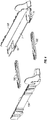
- FIG. 4 shows the side rails 10A, 10B and connectors 10C in exploded view.
- each connector 10C may slidably, and lockingly engage a receptacle 16 formed in the floor (7 in FIG. 3 ), which may be proximate a front and rear longitudinal end of each side rail 10A, 10B.
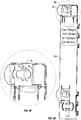
- FIG. 5 shows the connectors 10C assembled to the right hand side rail 10B, with the left hand side rail 10A still unassembled.
- FIG. 6 shows a bottom view of an assembled lane, wherein the connectors 10C are lockably disposed in respective receptacles 16.
- FIG. 6A shows one of the receptacles 16 in more detail with the connector 10C locked in place.
- the connector 10C may include a resilient, flexible locking tab 11 formed on each side.
- the locking tab 11 may include a detent bar 13 or similar feature extending from the surface of each locking tab 11.
- the detent bar 13 may engage any one of a plurality of locking slots A, B, C formed in a bottom surface of the receptacle 16. By engaging the detent bar 13 in the appropriate one of the locking slots A, B, C, the width of the lane (10 in FIG. 1 ) may be adjusted for selected size product containers ( FIG. 7 ).
- FIG. 6B shows one of the connectors 10C in oblique view to illustrate the resilient locking tabs 11.
- Each of the locking tabs 11 may be formed into the body 15 of the connector 10C such that the locking tabs 11 may be deflected in a direction normal to the plane of the connector body 15.
- FIG. 6C shows a side view of the connector 11 to illustrate that when the locking tabs (11 in FIG. 6B ) are undeflected, the detent bars 13 protrude slightly below the bottom plane 17 of the connector 10C so that the detent bars 13 may lockingly engage the selected slots (A, B, C in FIG. 6A ) in the respective receptacle (16 in FIG. 6 ).
- a bottom view of the connector 10C showing the detent bars 13 is shown in FIG. 6D .
- FIG. 6E shows a bottom view of the right hand side rail 10B to illustrate the position of the receptacles 16.
- FIG. 6F shows one of the receptacles 16 in more detail, illustrating the relative positions of the slots A, B, C.
- the locking tab (13 in FIG. 6B ) may be deflected slightly so that the detent bar (13 in FIG. 6C ) is free to move longitudinally within the receptacle 16.
- the locking tab 11 may be released to enable the detent bar 13 to engage the selected slot A, B, or C and lock the connector 10C to the respective side rail (10A, 10B in FIG. 3 ) in the selected one of the slots A, B or C.
- the width of each lane (10 in FIG. 1 ) may be selected for a specific size product container.
- the channels 18 formed in the side wall (9 in FIG. 3 ) of the left hand side rail 10A are longitudinally offset from the corresponding channels 18 formed in the right hand side wall 10b.
- Such longitudinal offset enables lanes to be placed side by side in a same longitudinal position with respect to each other while reducing the lateral spacing between laterally adjacent lanes (10 in FIG. 1 ).
- the effective lateral spacing between laterally adjacent lanes at a same relative longitudinal position may be settable to substantially zero, whereas if the channels were in the same longitudinal position on each side wall, the lanes would be laterally spaceable at a minimum of twice the lateral dimension of the channels 18,
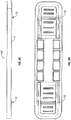
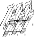
- FIG. 7 shows three lanes 10 assembled in "waterfall" configuration, wherein each vertically successively higher lane 10 is disposed longitudinally behind the lower vertically adjacent lane 10. Such configuration may make it easier for a user to access product containers 21 stored on each lane.
- FIG. 8 shows how such waterfall configuration may be formed by assembling successively higher lanes by inserting the vertical support connectors 14 in successively more forward channels 18A, 18B, 18C. It is within the scope of the present disclosure to assemble lanes vertically using a same respective channel for the vertical support connectors 14. Further, while the present example shows three sets of corresponding channels on each side wall, the number of channels is not a limitation on the scope of the present disclosure. Further, the number of lanes which may be vertically stacked is not a limitation on the scope of the present disclosure.
- a retail product container display system may be configured to accommodate various size product containers while being assembled from identical parts.
- a system according to the present disclosure may be configured for any selected vertical space while being assembled from identical parts.
Landscapes
- Details Of Rigid Or Semi-Rigid Containers (AREA)
- Stackable Containers (AREA)
Claims (8)
- Système de présentation de contenants de produits de détail, comprenant
au moins une allée de stockage de produits (10), l'au moins une allée de stockage de produits (10) comprenant un rail de gauche (10A) et un rail de droite (10B) ; et
au moins deux connecteurs (10C) engagés dans des réceptacles (16) prévus à cet effet sur chacun des deux rails de gauche et de droite (10A, 10B), les réceptacles (16) étant disposés à des positions correspondantes espacées longitudinalement le long de chacun des rails latéraux (10A, 10B), chacun des rails latéraux (10A, 10B) comprenant un rail vertical (9) et un plancher horizontal (7) ; et
une pluralité de canaux espacés longitudinalement (18) formés sur une surface extérieure de la paroi latérale (9) de chacun des rails latéraux (10A, 10B), les canaux (18) étant chacun conçu pour recevoir un connecteur support vertical (14) à l'intérieur, une pluralité d'allées (10) étant empilables verticalement, la pluralité de canaux espacés longitudinalement (18) étant conçus pour permettre un assemblage vertical de la pluralité d'allées (10) de manière à ce que des allées hautes (10) soient disposées successivement à une position longitudinale différente par rapport aux allées verticalement basses (10),
caractérisé en ce qu'une position longitudinale des canaux (18) sur la paroi latérale gauche (9) est décalée d'une position longitudinale des canaux (18) sur la paroi latérale droite (9) de manière à ce qu'un espace latéral entre des allées adjacentes placées latéralement (10) puisse être mis sensiblement à zéro. - Système selon la revendication 1, dans lequel chacun des au moins deux connecteurs (10C) comprend, de chaque côté, une languette de verrouillage orientable (11) dotée d'une barre de détente (13) sur une de ses surfaces et dans lequel les réceptacles (16) comprennent chacun une pluralité de fentes espacées latéralement (A, B, C) conçues pour s'engager dans la barre de détente (13) d'une extrémité respective d'un des au moins deux connecteurs (10C), une largeur de l'au moins une allée de stockage (10) étant ajustable.
- Système selon la revendication 2, dans lequel les réceptacles (16) sont disposés sur une surface de fond du plancher horizontal (7) de chacun des rails latéraux de gauche et de droite (10A, 10B).
- Système selon la revendication 1, dans lequel la pluralité de canaux espacés longitudinalement (18) sont conçus pour permettre un assemblage vertical d'une pluralité d'allées (10) et les allées adjacentes verticalement (10) sont interconnectés par un connecteur support (14) disposé dans chaque canal sélectionné parmi les canaux espacés (18) sur chacun des rails latéraux (10A, 10B).
- Système selon la revendication 1, comprenant en outre des pieds supports (12) pouvant être fixés à un fond de chacun des rails latéraux de gauche (10A) et de droite (10B), les pieds supports conférant à l'au moins une allée (10) une inclinaison sélectionnée.
- Système selon la revendication 1, comprenant en outre une barrière terminale (10D, 10E) disposée à une extrémité avant d'au moins un des rails latéraux de gauche (10A) et de droite (10B).
- Système selon la revendication 6, dans lequel la barrière terminale (10D, 10E) est partie intégrante de l'au moins un des rails latéraux de gauche (10A) et de droite (10B).
- Système selon la revendication 1, dans lequel chacun des rails latéraux (10A, 10B) comprend un arrêt avant et une extrémité arrière ; et dans lequel chacun des au moins deux connecteurs (10C) comprend de chaque côté une languette de verrouillage orientable (11) dotée d'une barre de détente (13) sur une de ses surfaces et dans lequel les réceptacles (16) comprennent chacun une pluralité de fentes espacées latéralement (A, B, C) conçues pour s'engager dans la barre de détente (13) d'une extrémité respective d'un des au moins deux connecteurs (10C), une largeur de l'au moins une allée de stockage (10) étant ajustable.
Priority Applications (1)
| Application Number | Priority Date | Filing Date | Title |
|---|---|---|---|
| EP18150281.6A EP3323321A1 (fr) | 2013-07-22 | 2014-07-01 | Système de présentation de récipient de produit au détail |
Applications Claiming Priority (1)
| Application Number | Priority Date | Filing Date | Title |
|---|---|---|---|
| US201361856774P | 2013-07-22 | 2013-07-22 |
Related Child Applications (2)
| Application Number | Title | Priority Date | Filing Date |
|---|---|---|---|
| EP18150281.6A Division EP3323321A1 (fr) | 2013-07-22 | 2014-07-01 | Système de présentation de récipient de produit au détail |
| EP18150281.6A Division-Into EP3323321A1 (fr) | 2013-07-22 | 2014-07-01 | Système de présentation de récipient de produit au détail |
Publications (2)
| Publication Number | Publication Date |
|---|---|
| EP2829201A1 EP2829201A1 (fr) | 2015-01-28 |
| EP2829201B1 true EP2829201B1 (fr) | 2018-05-23 |
Family
ID=51059326
Family Applications (2)
| Application Number | Title | Priority Date | Filing Date |
|---|---|---|---|
| EP14175187.5A Active EP2829201B1 (fr) | 2013-07-22 | 2014-07-01 | Système de présentation de récipient de produit au détail |
| EP18150281.6A Withdrawn EP3323321A1 (fr) | 2013-07-22 | 2014-07-01 | Système de présentation de récipient de produit au détail |
Family Applications After (1)
| Application Number | Title | Priority Date | Filing Date |
|---|---|---|---|
| EP18150281.6A Withdrawn EP3323321A1 (fr) | 2013-07-22 | 2014-07-01 | Système de présentation de récipient de produit au détail |
Country Status (4)
| Country | Link |
|---|---|
| US (1) | US20150021283A1 (fr) |
| EP (2) | EP2829201B1 (fr) |
| DK (1) | DK2829201T3 (fr) |
| ES (1) | ES2677114T3 (fr) |
Families Citing this family (11)
| Publication number | Priority date | Publication date | Assignee | Title |
|---|---|---|---|---|
| US9138076B2 (en) | 2014-01-24 | 2015-09-22 | Rtc Industries, Inc. | Product management display system |
| US10058195B2 (en) * | 2014-08-26 | 2018-08-28 | Menasha Corporation | Can dispenser |
| US9615674B2 (en) * | 2015-03-11 | 2017-04-11 | Trinity, Llc | Can dispenser and merchandiser |
| US10251494B1 (en) | 2017-12-01 | 2019-04-09 | Southern Imperial Llc | Retail merchandise tray |
| US11350768B2 (en) | 2017-12-01 | 2022-06-07 | Fasteners For Retail, Inc. | Retail merchandise tray |
| US10034557B1 (en) * | 2017-12-01 | 2018-07-31 | Southern Imperial Llc | Retail merchandise tray |
| US11583107B2 (en) * | 2020-01-22 | 2023-02-21 | Fasteners For Retail, Inc. | Retail merchandise tray |
| US11166571B2 (en) | 2020-01-22 | 2021-11-09 | Fasteners For Retail, Inc. | Retail merchandise tray |
| US11517127B2 (en) | 2020-08-05 | 2022-12-06 | Fasteners for Retails, Inc. | Retail merchandise tray with mounting, spacing and locating |
| US12245706B1 (en) | 2023-09-13 | 2025-03-11 | Fasteners For Retail, Inc. | Pull-out tray for shelving |
| US20260060451A1 (en) * | 2024-09-02 | 2026-03-05 | Inventory Systems Gmbh | Goods presentaton system with at least one separating element |
Citations (4)
| Publication number | Priority date | Publication date | Assignee | Title |
|---|---|---|---|---|
| US4228903A (en) * | 1979-04-26 | 1980-10-21 | Thomas A. Schutz Co., Inc. | Gravity feed can dispenser for beverage coolers |
| US4356923A (en) * | 1980-05-22 | 1982-11-02 | Visual Marketing, Inc. | Storage and dispensing rack |
| US4685574A (en) * | 1984-01-10 | 1987-08-11 | Visual Marketing Inc. | Shelf-supported expandable gravity feed system |
| USRE33515E (en) * | 1983-12-05 | 1991-01-08 | The Mead Corporation | Gravity feed display device |
Family Cites Families (23)
| Publication number | Priority date | Publication date | Assignee | Title |
|---|---|---|---|---|
| US2588618A (en) * | 1948-03-24 | 1952-03-11 | Simon Di Renzo | Egg storage and dispensing device |
| US2888145A (en) * | 1953-12-30 | 1959-05-26 | Knott Joseph Fred | Bin dispenser |
| US2915162A (en) * | 1959-06-04 | 1959-12-01 | Donald E Umstead | Bin dispenser |
| US3306688A (en) * | 1965-04-05 | 1967-02-28 | Domenico Joseph Di | Article dispensing rack |
| US4364481A (en) * | 1980-10-20 | 1982-12-21 | Bristol-Myers Company | Shelf organizer |
| US4474297A (en) * | 1983-01-03 | 1984-10-02 | Rtc Industries, Inc. | Storage and dispenser rack |
| US4598828A (en) * | 1983-02-22 | 1986-07-08 | Visual Marketing, Inc. | Storage and dispensing rack |
| US4537316A (en) * | 1983-07-01 | 1985-08-27 | Thomas A. Schutz Co., Inc. | Modular display for cigarette packs |
| US4785943A (en) * | 1986-12-09 | 1988-11-22 | Visual Marketing, Inc. | Expandable storage and dispensing system |
| US5069349A (en) * | 1990-06-20 | 1991-12-03 | Wear Philip A | Display rack structure |
| US5366099A (en) * | 1994-02-02 | 1994-11-22 | Consumer Promotions, Inc. | Adjustable display unit |
| US5806690A (en) * | 1997-03-31 | 1998-09-15 | Gamon International, Inc. | Adjustable shelving |
| US6357606B1 (en) * | 1999-02-02 | 2002-03-19 | Hmg Worldwide In-Store Marketing, Inc. | Modular self-adjusting merchandise display system |
| AU2002258996A1 (en) * | 2001-04-26 | 2002-11-11 | Dci Marketing, Inc. | Merchandising system |
| CA2447076C (fr) * | 2001-05-17 | 2007-08-21 | Rtc Industries, Inc. | Systeme d'etalage concu pour la gestion de produits |
| US7168579B2 (en) * | 2002-09-06 | 2007-01-30 | Dci Marketing, Inc. | Merchandising system |
| US7458473B1 (en) * | 2005-12-06 | 2008-12-02 | New Dimensions Research Corporation | Display shelf |
| US7703614B2 (en) * | 2006-01-27 | 2010-04-27 | Display Technologies | Product display tray |
| US8066128B2 (en) * | 2007-08-28 | 2011-11-29 | Smart Systems, Inc. | Integrated shelf allocation management system |
| US9198527B2 (en) * | 2007-09-27 | 2015-12-01 | William R. Goehring | Space saving manual shelf management system |
| US7992726B2 (en) * | 2007-09-27 | 2011-08-09 | Shelf Advance, Inc. | Space saving manual shelf management system |
| WO2011087647A1 (fr) * | 2009-12-09 | 2011-07-21 | Goehring William R | Système manuel de gestion d'étagères économiseur d'espace et unité d'emballage prête au rangement sur étagère |
| US8851303B2 (en) * | 2008-07-29 | 2014-10-07 | Smart Systems, Inc. | Integrated shelf allocation management system |
-
2014
- 2014-05-16 US US14/279,426 patent/US20150021283A1/en not_active Abandoned
- 2014-07-01 ES ES14175187.5T patent/ES2677114T3/es active Active
- 2014-07-01 EP EP14175187.5A patent/EP2829201B1/fr active Active
- 2014-07-01 EP EP18150281.6A patent/EP3323321A1/fr not_active Withdrawn
- 2014-07-01 DK DK14175187.5T patent/DK2829201T3/en active
Patent Citations (4)
| Publication number | Priority date | Publication date | Assignee | Title |
|---|---|---|---|---|
| US4228903A (en) * | 1979-04-26 | 1980-10-21 | Thomas A. Schutz Co., Inc. | Gravity feed can dispenser for beverage coolers |
| US4356923A (en) * | 1980-05-22 | 1982-11-02 | Visual Marketing, Inc. | Storage and dispensing rack |
| USRE33515E (en) * | 1983-12-05 | 1991-01-08 | The Mead Corporation | Gravity feed display device |
| US4685574A (en) * | 1984-01-10 | 1987-08-11 | Visual Marketing Inc. | Shelf-supported expandable gravity feed system |
Also Published As
| Publication number | Publication date |
|---|---|
| US20150021283A1 (en) | 2015-01-22 |
| ES2677114T3 (es) | 2018-07-30 |
| EP2829201A1 (fr) | 2015-01-28 |
| EP3323321A1 (fr) | 2018-05-23 |
| DK2829201T3 (en) | 2018-08-06 |
Similar Documents
| Publication | Publication Date | Title |
|---|---|---|
| EP2829201B1 (fr) | Système de présentation de récipient de produit au détail | |
| US10098478B2 (en) | Product merchandising system | |
| US11583108B2 (en) | Product management display system | |
| US8317038B2 (en) | Modular display and dispensing apparatus with plural dispensing tiers | |
| US7086541B2 (en) | Flexible front merchandising display device | |
| US7497342B2 (en) | Product management display system | |
| RU2486857C2 (ru) | Витринная система управления товаром с механизмом безрельсового толкателя | |
| US7628282B2 (en) | Product management display system | |
| US8651288B2 (en) | Shelf and merchandise display system | |
| US6695152B1 (en) | Merchandising display track device | |
| US20110290749A1 (en) | Product display system with adjustable bracket | |
| US20070119798A1 (en) | Beverage container shelf management system | |
| CN107249399B (zh) | 具有无轨道推进器机构的产品管理展示系统 | |
| US9220355B2 (en) | Shelf and merchandise display system having stowable lane dividers | |
| HK1167073B (en) | Product management display system with trackless pusher mechanism | |
| HK1167073A1 (en) | Product management display system with trackless pusher mechanism |
Legal Events
| Date | Code | Title | Description |
|---|---|---|---|
| 17P | Request for examination filed |
Effective date: 20140701 |
|
| AK | Designated contracting states |
Kind code of ref document: A1 Designated state(s): AL AT BE BG CH CY CZ DE DK EE ES FI FR GB GR HR HU IE IS IT LI LT LU LV MC MK MT NL NO PL PT RO RS SE SI SK SM TR |
|
| AX | Request for extension of the european patent |
Extension state: BA ME |
|
| PUAI | Public reference made under article 153(3) epc to a published international application that has entered the european phase |
Free format text: ORIGINAL CODE: 0009012 |
|
| R17P | Request for examination filed (corrected) |
Effective date: 20150211 |
|
| RBV | Designated contracting states (corrected) |
Designated state(s): AL AT BE BG CH CY CZ DE DK EE ES FI FR GB GR HR HU IE IS IT LI LT LU LV MC MK MT NL NO PL PT RO RS SE SI SK SM TR |
|
| 17Q | First examination report despatched |
Effective date: 20150424 |
|
| STAA | Information on the status of an ep patent application or granted ep patent |
Free format text: STATUS: EXAMINATION IS IN PROGRESS |
|
| GRAP | Despatch of communication of intention to grant a patent |
Free format text: ORIGINAL CODE: EPIDOSNIGR1 |
|
| STAA | Information on the status of an ep patent application or granted ep patent |
Free format text: STATUS: GRANT OF PATENT IS INTENDED |
|
| INTG | Intention to grant announced |
Effective date: 20180102 |
|
| GRAS | Grant fee paid |
Free format text: ORIGINAL CODE: EPIDOSNIGR3 |
|
| GRAA | (expected) grant |
Free format text: ORIGINAL CODE: 0009210 |
|
| STAA | Information on the status of an ep patent application or granted ep patent |
Free format text: STATUS: THE PATENT HAS BEEN GRANTED |
|
| AK | Designated contracting states |
Kind code of ref document: B1 Designated state(s): AL AT BE BG CH CY CZ DE DK EE ES FI FR GB GR HR HU IE IS IT LI LT LU LV MC MK MT NL NO PL PT RO RS SE SI SK SM TR |
|
| REG | Reference to a national code |
Ref country code: GB Ref legal event code: FG4D |
|
| REG | Reference to a national code |
Ref country code: CH Ref legal event code: EP |
|
| REG | Reference to a national code |
Ref country code: IE Ref legal event code: FG4D |
|
| REG | Reference to a national code |
Ref country code: AT Ref legal event code: REF Ref document number: 1000811 Country of ref document: AT Kind code of ref document: T Effective date: 20180615 |
|
| REG | Reference to a national code |
Ref country code: DE Ref legal event code: R096 Ref document number: 602014025772 Country of ref document: DE |
|
| REG | Reference to a national code |
Ref country code: FR Ref legal event code: PLFP Year of fee payment: 5 |
|
| REG | Reference to a national code |
Ref country code: ES Ref legal event code: FG2A Ref document number: 2677114 Country of ref document: ES Kind code of ref document: T3 Effective date: 20180730 |
|
| REG | Reference to a national code |
Ref country code: NL Ref legal event code: FP |
|
| REG | Reference to a national code |
Ref country code: DK Ref legal event code: T3 Effective date: 20180731 |
|
| REG | Reference to a national code |
Ref country code: SE Ref legal event code: TRGR |
|
| REG | Reference to a national code |
Ref country code: LT Ref legal event code: MG4D |
|
| REG | Reference to a national code |
Ref country code: NO Ref legal event code: T2 Effective date: 20180523 |
|
| PG25 | Lapsed in a contracting state [announced via postgrant information from national office to epo] |
Ref country code: BG Free format text: LAPSE BECAUSE OF FAILURE TO SUBMIT A TRANSLATION OF THE DESCRIPTION OR TO PAY THE FEE WITHIN THE PRESCRIBED TIME-LIMIT Effective date: 20180823 Ref country code: LT Free format text: LAPSE BECAUSE OF FAILURE TO SUBMIT A TRANSLATION OF THE DESCRIPTION OR TO PAY THE FEE WITHIN THE PRESCRIBED TIME-LIMIT Effective date: 20180523 |
|
| PG25 | Lapsed in a contracting state [announced via postgrant information from national office to epo] |
Ref country code: LV Free format text: LAPSE BECAUSE OF FAILURE TO SUBMIT A TRANSLATION OF THE DESCRIPTION OR TO PAY THE FEE WITHIN THE PRESCRIBED TIME-LIMIT Effective date: 20180523 Ref country code: HR Free format text: LAPSE BECAUSE OF FAILURE TO SUBMIT A TRANSLATION OF THE DESCRIPTION OR TO PAY THE FEE WITHIN THE PRESCRIBED TIME-LIMIT Effective date: 20180523 Ref country code: RS Free format text: LAPSE BECAUSE OF FAILURE TO SUBMIT A TRANSLATION OF THE DESCRIPTION OR TO PAY THE FEE WITHIN THE PRESCRIBED TIME-LIMIT Effective date: 20180523 Ref country code: GR Free format text: LAPSE BECAUSE OF FAILURE TO SUBMIT A TRANSLATION OF THE DESCRIPTION OR TO PAY THE FEE WITHIN THE PRESCRIBED TIME-LIMIT Effective date: 20180824 |
|
| PG25 | Lapsed in a contracting state [announced via postgrant information from national office to epo] |
Ref country code: PL Free format text: LAPSE BECAUSE OF FAILURE TO SUBMIT A TRANSLATION OF THE DESCRIPTION OR TO PAY THE FEE WITHIN THE PRESCRIBED TIME-LIMIT Effective date: 20180523 Ref country code: EE Free format text: LAPSE BECAUSE OF FAILURE TO SUBMIT A TRANSLATION OF THE DESCRIPTION OR TO PAY THE FEE WITHIN THE PRESCRIBED TIME-LIMIT Effective date: 20180523 Ref country code: SK Free format text: LAPSE BECAUSE OF FAILURE TO SUBMIT A TRANSLATION OF THE DESCRIPTION OR TO PAY THE FEE WITHIN THE PRESCRIBED TIME-LIMIT Effective date: 20180523 Ref country code: RO Free format text: LAPSE BECAUSE OF FAILURE TO SUBMIT A TRANSLATION OF THE DESCRIPTION OR TO PAY THE FEE WITHIN THE PRESCRIBED TIME-LIMIT Effective date: 20180523 Ref country code: CZ Free format text: LAPSE BECAUSE OF FAILURE TO SUBMIT A TRANSLATION OF THE DESCRIPTION OR TO PAY THE FEE WITHIN THE PRESCRIBED TIME-LIMIT Effective date: 20180523 |
|
| REG | Reference to a national code |
Ref country code: DE Ref legal event code: R097 Ref document number: 602014025772 Country of ref document: DE |
|
| PG25 | Lapsed in a contracting state [announced via postgrant information from national office to epo] |
Ref country code: SM Free format text: LAPSE BECAUSE OF FAILURE TO SUBMIT A TRANSLATION OF THE DESCRIPTION OR TO PAY THE FEE WITHIN THE PRESCRIBED TIME-LIMIT Effective date: 20180523 Ref country code: IT Free format text: LAPSE BECAUSE OF FAILURE TO SUBMIT A TRANSLATION OF THE DESCRIPTION OR TO PAY THE FEE WITHIN THE PRESCRIBED TIME-LIMIT Effective date: 20180523 |
|
| PG25 | Lapsed in a contracting state [announced via postgrant information from national office to epo] |
Ref country code: LU Free format text: LAPSE BECAUSE OF NON-PAYMENT OF DUE FEES Effective date: 20180701 Ref country code: MC Free format text: LAPSE BECAUSE OF FAILURE TO SUBMIT A TRANSLATION OF THE DESCRIPTION OR TO PAY THE FEE WITHIN THE PRESCRIBED TIME-LIMIT Effective date: 20180523 |
|
| PLBE | No opposition filed within time limit |
Free format text: ORIGINAL CODE: 0009261 |
|
| STAA | Information on the status of an ep patent application or granted ep patent |
Free format text: STATUS: NO OPPOSITION FILED WITHIN TIME LIMIT |
|
| 26N | No opposition filed |
Effective date: 20190226 |
|
| PG25 | Lapsed in a contracting state [announced via postgrant information from national office to epo] |
Ref country code: SI Free format text: LAPSE BECAUSE OF FAILURE TO SUBMIT A TRANSLATION OF THE DESCRIPTION OR TO PAY THE FEE WITHIN THE PRESCRIBED TIME-LIMIT Effective date: 20180523 |
|
| PG25 | Lapsed in a contracting state [announced via postgrant information from national office to epo] |
Ref country code: AL Free format text: LAPSE BECAUSE OF FAILURE TO SUBMIT A TRANSLATION OF THE DESCRIPTION OR TO PAY THE FEE WITHIN THE PRESCRIBED TIME-LIMIT Effective date: 20180523 |
|
| PG25 | Lapsed in a contracting state [announced via postgrant information from national office to epo] |
Ref country code: MT Free format text: LAPSE BECAUSE OF NON-PAYMENT OF DUE FEES Effective date: 20180701 |
|
| PG25 | Lapsed in a contracting state [announced via postgrant information from national office to epo] |
Ref country code: TR Free format text: LAPSE BECAUSE OF FAILURE TO SUBMIT A TRANSLATION OF THE DESCRIPTION OR TO PAY THE FEE WITHIN THE PRESCRIBED TIME-LIMIT Effective date: 20180523 |
|
| PG25 | Lapsed in a contracting state [announced via postgrant information from national office to epo] |
Ref country code: HU Free format text: LAPSE BECAUSE OF FAILURE TO SUBMIT A TRANSLATION OF THE DESCRIPTION OR TO PAY THE FEE WITHIN THE PRESCRIBED TIME-LIMIT; INVALID AB INITIO Effective date: 20140701 Ref country code: PT Free format text: LAPSE BECAUSE OF FAILURE TO SUBMIT A TRANSLATION OF THE DESCRIPTION OR TO PAY THE FEE WITHIN THE PRESCRIBED TIME-LIMIT Effective date: 20180523 |
|
| PG25 | Lapsed in a contracting state [announced via postgrant information from national office to epo] |
Ref country code: MK Free format text: LAPSE BECAUSE OF NON-PAYMENT OF DUE FEES Effective date: 20180523 Ref country code: CY Free format text: LAPSE BECAUSE OF FAILURE TO SUBMIT A TRANSLATION OF THE DESCRIPTION OR TO PAY THE FEE WITHIN THE PRESCRIBED TIME-LIMIT Effective date: 20180523 |
|
| PG25 | Lapsed in a contracting state [announced via postgrant information from national office to epo] |
Ref country code: IS Free format text: LAPSE BECAUSE OF FAILURE TO SUBMIT A TRANSLATION OF THE DESCRIPTION OR TO PAY THE FEE WITHIN THE PRESCRIBED TIME-LIMIT Effective date: 20180923 |
|
| REG | Reference to a national code |
Ref country code: AT Ref legal event code: UEP Ref document number: 1000811 Country of ref document: AT Kind code of ref document: T Effective date: 20180523 |
|
| PGFP | Annual fee paid to national office [announced via postgrant information from national office to epo] |
Ref country code: NL Payment date: 20250723 Year of fee payment: 12 |
|
| PGFP | Annual fee paid to national office [announced via postgrant information from national office to epo] |
Ref country code: ES Payment date: 20250819 Year of fee payment: 12 Ref country code: FI Payment date: 20250722 Year of fee payment: 12 |
|
| PGFP | Annual fee paid to national office [announced via postgrant information from national office to epo] |
Ref country code: DE Payment date: 20250722 Year of fee payment: 12 Ref country code: DK Payment date: 20250723 Year of fee payment: 12 |
|
| PGFP | Annual fee paid to national office [announced via postgrant information from national office to epo] |
Ref country code: NO Payment date: 20250722 Year of fee payment: 12 |
|
| PGFP | Annual fee paid to national office [announced via postgrant information from national office to epo] |
Ref country code: BE Payment date: 20250722 Year of fee payment: 12 Ref country code: GB Payment date: 20250724 Year of fee payment: 12 |
|
| PGFP | Annual fee paid to national office [announced via postgrant information from national office to epo] |
Ref country code: FR Payment date: 20250723 Year of fee payment: 12 Ref country code: AT Payment date: 20250721 Year of fee payment: 12 |
|
| PGFP | Annual fee paid to national office [announced via postgrant information from national office to epo] |
Ref country code: SE Payment date: 20250723 Year of fee payment: 12 Ref country code: CH Payment date: 20250801 Year of fee payment: 12 |
|
| PGFP | Annual fee paid to national office [announced via postgrant information from national office to epo] |
Ref country code: IE Payment date: 20250723 Year of fee payment: 12 |