EP2829167B1 - Distributor for a pneumatic distribution machine - Google Patents
Distributor for a pneumatic distribution machine Download PDFInfo
- Publication number
- EP2829167B1 EP2829167B1 EP14401076.6A EP14401076A EP2829167B1 EP 2829167 B1 EP2829167 B1 EP 2829167B1 EP 14401076 A EP14401076 A EP 14401076A EP 2829167 B1 EP2829167 B1 EP 2829167B1
- Authority
- EP
- European Patent Office
- Prior art keywords
- distributor
- shut
- space
- slider
- distribution
- Prior art date
- Legal status (The legal status is an assumption and is not a legal conclusion. Google has not performed a legal analysis and makes no representation as to the accuracy of the status listed.)
- Active
Links
- 238000009826 distribution Methods 0.000 title claims description 52
- 239000003337 fertilizer Substances 0.000 claims description 2
- 239000000463 material Substances 0.000 description 18
- 238000009827 uniform distribution Methods 0.000 description 6
- 235000014347 soups Nutrition 0.000 description 1
Images


Classifications
-
- A—HUMAN NECESSITIES
- A01—AGRICULTURE; FORESTRY; ANIMAL HUSBANDRY; HUNTING; TRAPPING; FISHING
- A01C—PLANTING; SOWING; FERTILISING
- A01C7/00—Sowing
- A01C7/08—Broadcast seeders; Seeders depositing seeds in rows
- A01C7/081—Seeders depositing seeds in rows using pneumatic means
- A01C7/084—Pneumatic distribution heads for seeders
Definitions
- the invention relates to a distributor for a pneumatic distributor according to the preamble of claim 1.
- Such a distributor is for example by the DE 102 10 010 B4 known.
- a gate valve is provided, which has the shape of a concentric to the annular space distributor cylinder section.
- This gate valve By means of this gate valve several inlet openings of distribution lines can be shut off at the same time, so that the working width is reduced in a simple manner.
- the side ends terminate at a considerable distance from the side walls of the distributor space. This is advantageous to the extent that a portion of the supplied air can escape via the distribution lines shut off from the distribution of material, so that a uniform distribution of the supplied material is maintained on the unrestricted distribution lines.
- the side ends terminate here directly in mounted on the side walls of the distribution space sliding guides. This in so far advantageous that the closed distribution lines are completely shut off and no material can get to the closed distribution lines. As a result of the fact that the air supplied to the blocked-off distribution lines does not want to be able to escape via the blocked distributor lines, the uniform distribution of the supplied material to the un-blocked distribution lines is disturbed.
- the invention has for its object to provide a simple remedy.
- the arrangement of the gate valve can be optimized in a simple manner.
- a particularly effective shielding of the blocked distribution lines, so that no possible material reaches the shut-off distribution lines is achieved in that the plate-shaped guide elements are arranged at an inserted into the distributor chamber gate valve in the direction of not closed off distributor space in a staggered manner before the side ends of the gate valve.
- An advantageous orientation of the guide elements is achieved in that the plate-shaped guide elements are arranged aligned at least approximately in the radial direction.
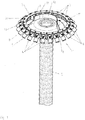
- the in the Fig. 1 to 3 illustrated distributor head 1 is part of a pneumatic metering and distribution system of a pneumatic working agricultural distributor.
- the research pipe 2 which is acted upon by a pneumatic conveying air flow, which is generated by a motor-driven fan, the redesignate material, such as seed or fertilizer is fed in an adjustable manner to the arranged at the end of the feed tube 2 header 1.
- the distributor head 1 the material is divided in a known manner to the leading to individual Ausbringorganen inlet openings 3 distribution lines 4.
- the distributor chamber 5 of the distributor head 1 is designed in a ring shape. From the distributor head 1, as already mentioned, several supply lines 4, which have inlet openings 3, lead away.
- the distributor head 1 is a gate valve 6, which is inserted from below into the distributor chamber 5 of the distributor head 1 assigned.
- This gate valve 6 is to be inserted into the distribution chamber 5 for shutting off, so that some inlet openings 3 of the distribution lines 4 can be shut off, and moved out of the distribution chamber 5, so that the supplied material is distributed to all inlet openings 3 of the distribution lines 4 in a uniform manner.
- the gate valve 6 is in its shut-off according to the Fig. 1 spaced from the inlet openings 3 of the distribution lines 4 and arranged to the side walls 7 of the distribution space 5, so that the air from the Supply line 2 to the inlet openings 3 of the shut-off distribution lines through the gap 8 between the side ends 9 of the gate valve 6 and the adjacent side walls 7 of the distributor head 1 passes, such as Fig. 1 and 2 demonstrate.
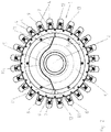
- the gate valve 6 has in the embodiment, as in Fig. 2 can be seen, the shape of a non-concentric to the annular distribution chamber 5 cylinder section.
- the gate valve has in its immediately adjacent to the supply line 2 a slide portion 10 which has a the circular contour of the supply line 2 and the annular distribution chamber 5 similar and / or adapted curve shape.
- At this central region 10 of the gate valve 6 close each on each side of an opposite curvature having slide portions 11 at. These sections 11 terminate in straight areas.
- the gate valve 6 has in its immediately adjacent to the supply line 2 an at least approximately annular cylinder portion 10 which extends over a range between 70 ° and 120 °, preferably about 90 °, and at least approximately concentric with the circular contour of the supply line 2 and annular distribution space runs.
- At this central region 10 of the gate valve 6 close to the center formed as a circle portion 10 each on each side of an opposite curvature having slide portions 11, which in the embodiment according to Fig. 2 leak into a straight area.
- the gate valve 6 thus has a wave-shaped contour course. Furthermore, this contour curve is such that it resembles the cross section of a deep-drawn soup plate with a plate edge.
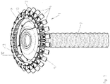
- the slider 6 can be pulled out by means not shown motor elements in an inoperative position of the distributor chamber 5, such as Fig. 3 shows that it does not interfere with the uniform distribution of seeds fed pneumatically via the supply line 2 to the distributor space 5, so that in the distributor space 5 the seed can be distributed in a uniform manner to the individual inlet openings 3 leading to the distributor lines 4.
- the plate-shaped guide elements 12 approaching the side walls 7 of the distributor chamber 5 are arranged in the region of the side ends 9 of the slide valve 6, like the Fig. 1 to 3 demonstrate.
- the arrangement is such that between the side ends 9 of the gate valve 6 and the free ends 13 of the plate-shaped guide elements 12, a gap-like distance 8 is present, as the Fig. 1 and 2 demonstrate.
- the plate-shaped guide elements 12 are arranged aligned at least approximately in the radial direction.
- the plate-shaped guide elements 12 are arranged at least approximately opposite one another.
- the plate-shaped guide elements 12 are arranged with inserted into the distributor chamber 5 gate valve 6 in the direction of the non-isolated distributor space in a staggered manner before the side ends 9 of the gate valve 6.
- the embodiment according to the 4 to 6 differs from the embodiment according to the Fig. 1 to 3 in that, in addition, a further gate valve 6, which is also located opposite the first gate valve 6 and can likewise be inserted into the distributor chamber 5 for shutting off distribution lines 4, is arranged in the distributor chamber 5.
- a further gate valve 6 which is also located opposite the first gate valve 6 and can likewise be inserted into the distributor chamber 5 for shutting off distribution lines 4, is arranged in the distributor chamber 5.
- Fig. 4 is the one in the Representation rear gate valve 6 is inserted into its shut-off position in the distribution chamber 5, while according to Fig. 6 the front gate valve 6 'in the representation is pushed into its shut-off position into the distributor chamber 5.
Landscapes
- Life Sciences & Earth Sciences (AREA)
- Soil Sciences (AREA)
- Environmental Sciences (AREA)
- Sliding Valves (AREA)
- Fertilizing (AREA)
Description
Die Erfindung betrifft einen Verteiler für eine pneumatische Verteilmaschine gemäß dem Oberbegriff des Patentanspruches 1.The invention relates to a distributor for a pneumatic distributor according to the preamble of
Ein derartiger Verteiler ist beispielsweise durch die
Der Erfindung liegt die Aufgabe zugrunde, hier auf einfache Weise Abhilfe zu schaffen.The invention has for its object to provide a simple remedy.
Diese Aufgabe wird erfindungsgemäß durch die kennzeichnenden Merkmale des Anspruches 1 gelöst.This object is achieved by the characterizing features of
Infolge dieser Maßnahmen lässt sich die Anordnung des Absperrschiebers in einfacher Weise optimieren. Einerseits bleibt eine ausreichend große Durchtrittsöffnung für einen Teil der zugeführten Luft, die über die an sich von der Materialverteilung abgesperrten Verteilerleitungen entweichen kann, so dass eine gleichmäßige Aufteilung des zugeführten Materiales auf die nicht abgesperrten Verteilerleitungen erhalten bleibt. Andererseits verhindern die plattenförmigen Leitelemente in verbesserter Weise, dass Material aus dem Verteilerraum zu den abgesperrten Verteilerleitungen gelangt.As a result of these measures, the arrangement of the gate valve can be optimized in a simple manner. On the one hand, there remains a sufficiently large passage opening for a part of the supplied air, which can escape via the distribution lines shut off from the distribution of material, so that a uniform distribution of the supplied material is maintained on the not closed off distribution lines. On the other hand, improve the plate-shaped vanes in an improved way that material from the distribution chamber arrives at the shut-off distribution lines.
Ein besonders wirksames Abschirmen der abgesperrten Verteilerleitungen, damit möglichst kein Material zu den abgesperrten Verteilerleitungen gelangt, wird dadurch erreicht, dass die plattenförmigen Leitelemente bei in den Verteilerraum eingeschobenen Absperrschieber in Richtung des nicht abgesperrten Verteilerraumes in versetzter Weise vor den Seitenenden des Absperrschiebers angeordnet sind.A particularly effective shielding of the blocked distribution lines, so that no possible material reaches the shut-off distribution lines is achieved in that the plate-shaped guide elements are arranged at an inserted into the distributor chamber gate valve in the direction of not closed off distributor space in a staggered manner before the side ends of the gate valve.
Eine vorteilhafte Ausrichtung der Leitelemente wird dadurch erreicht, dass die plattenförmigen Leitelemente zumindest annähernd in radialer Richtung ausgerichtet angeordnet sind.An advantageous orientation of the guide elements is achieved in that the plate-shaped guide elements are arranged aligned at least approximately in the radial direction.
Eine vorteilhafte Ausrichtung der Leitelemente, insbesondere wenn wahlweise die eine oder andere Hälfte der Verteilerleitungen abgesperrt werden soll, wird dadurch erreicht, dass die plattenförmigen Leitelemente zumindest annähernd gegenüberliegend angeordnet sind.An advantageous alignment of the guide elements, in particular if either one or the other half of the distribution lines to be shut off, is achieved in that the plate-shaped guide elements are arranged at least approximately opposite.
Weitere Einzelheiten der Erfindung sind der Beispielsbeschreibung und den Zeichnungen zu entnehmen. Hierbei zeigen
- Fig. 1
- den Verteilerkopf eines pneumatischen Verteil- und Dosiersystems mit im Halbschnitt dargestellten Verteilerkopfdeckel, wobei der Absperrschieber sich in seiner Absperrposition befindet, in perspektivischer Darstellung,
- Fig. 2
- den Verteilerkopf in der Darstellungsweise nach
Fig. 1 , in Draufsicht, - Fig. 3
- den Verteilerkopf nach
Fig. 1 , wobei der Absperrschieber sich in seiner eingezogenen Position befindet, in perspektivischer Darstellung, - Fig. 4
- einen weiteren Verteilerkopf eines pneumatischen Verteil- und Dosiersystems mit im Halbschnitt dargestellten Verteilerkopfdeckel, wobei zwei gegenüber liegende Absperrschieber im Verteilerraum einschiebbar sind und sich der eine Absperrschieber in seiner Absperrposition und der andere Absperrschieber sich in seiner eingezogenen Position befindet, in perspektivischer Darstellung,
- Fig. 5
- den Verteilerkopf in der Darstellungsweise nach
Fig. 4 , in Draufsicht, - Fig. 6
- den Verteilerkopf nach
Fig. 4 , wobei sich der eine Absperrschieber in seiner Absperrposition und der andere Absperrschieber sich in seiner eingezogenen Position befindet, jedoch gewechselt im Vergleich zuFig.4 , in perspektivischer Darstellung.
- Fig. 1
- the distributor head of a pneumatic distribution and metering system with distributor head cover shown in half section, wherein the gate valve is in its shut-off position, in perspective view,
- Fig. 2
- the distributor head as shown
Fig. 1 , in plan view, - Fig. 3
- the distributor head
Fig. 1 , wherein the gate valve is in its retracted position, in perspective, - Fig. 4
- a further distribution head of a pneumatic distribution and metering system with a distributor head cover shown in half section, wherein two opposing gate valves are inserted in the distributor space and the one gate valve in its shut-off position and the other gate valve is in its retracted position, in perspective,
- Fig. 5
- the distributor head as shown
Fig. 4 , in plan view, - Fig. 6
- the distributor head
Fig. 4 with one gate valve in its shut off position and the other gate valve in its retracted position, but changed compared toFigure 4 , in perspective.
Der in den
Über das Zuführrohr 2, welches mit einem pneumatischen Förderluftstrom, der von einem motorisch angetriebenen Gebläse erzeugt wird, beaufschlagt ist, wird dem am Ende des Zuführrohres 2 angeordneten Verteilerkopf 1 das auszubringende Material, beispielsweise Saatgut oder Dünger in einstellbarer Weise zugeführt. Über den Verteilerkopf 1 wird das Material in bekannter Weise auf die zu einzelnen Ausbringorganen führenden Eintrittsöffnungen 3 aufweisenden Verteilerleitungen 4 aufgeteilt.About the
Der Verteilerraum 5 des Verteilerkopfes 1 ist ringförmig ausgestaltet. Von dem Verteilerkopf 1 aus führen, wie bereits erwähnt, mehrere Zuführleitungen 4, die Eintrittsöffnungen 3 aufweisen, weg.The
Dem Verteilerkopf 1 ist ein Absperrschieber 6, der von unten in den Verteilerraum 5 des Verteilerkopfes 1 einschiebbar ist, zugeordnet. Dieser Absperrschieber 6 ist in den Verteilerraum 5 zum Absperren einzuschieben, so dass also einige Eintrittsöffnungen 3 der Verteilerleitungen 4 absperrbar sind, und aus dem Verteilerraum 5 herausbewegbar, so dass das zugeführte Material auf alle Eintrittsöffnungen 3 der Verteilerleitungen 4 in gleichmäßiger Weise aufgeteilt wird.The
Der Absperrschieber 6 ist in seiner Absperrstellung entsprechend der
Der Absperrschieber 6 weist in dem Ausführungsbeispiel, wie in
Der Absperrschieber 6 weist in seinem der Zuführleitung 2 unmittelbar benachbarten Bereich einen zumindest annähernd ringförmigen Zylinderabschnitt 10 auf, der sich über einen Bereich zwischen 70° und 120°, vorzugsweise etwa 90°, erstreckt und zumindest annähernd konzentrisch zu der Kreiskontur der Zuführleitung 2 und des ringförmigen Verteilerraumes verläuft. An diesem mittleren Bereich 10 des Absperrschiebers 6 schließen sich mit zum dem mittleren als Kreisabschnitt ausgebildeten Bereich 10 jeweils auf jeder Seite eine entgegen gesetzte Krümmung aufweisende Schieberabschnitte 11 an, die im Ausführungsbeispiel gemäß
Der Schieber 6 kann mittels nicht dargestellter motorischer Elemente in eine Außerbetriebsposition aus dem Verteilerraum 5 herausgezogen werden, wie
The
Weiterhin kann mittels des motorischen Einstellelementes der Absperrschieber 6 in die in
In dem Verteilerraum sind die an die Seitenwandungen 7 des Verteilerraumes 5 heranreichende plattenförmigen Leitelemente 12 in dem Bereich der Seitenenden 9 des Absperrschiebers 6 angeordnet, wie die
Somit wird durch die Anordnung der Leitelemente 12 in der beschrieben Zuordnung zu den Absperrschiebern 6 in einfacher Weise optimiert. Einerseits bleibt eine ausreichend große Durchtrittsöffnung 8 für einen Teil der zugeführten Luft, die über die an sich von der Materialverteilung abgesperrten Verteilerleitungen 4 entweichen kann, so dass eine gleichmäßige Aufteilung des zugeführten Materiales auf die nicht abgesperrten Verteilerleitungen 4 erhalten bleibt. Andererseits verhindern die plattenförmigen Leitelemente 12 in verbesserter Weise, dass Material aus dem Verteilerraum 5 zu den abgesperrten Verteilerleitungen 4 gelangt.Thus, is optimized by the arrangement of the
Das Ausführungsbeispiel gemäß den
Claims (4)
- Distributor (1) for a pneumatic distribution machine for seeds, fertilizer and the like, having the following features:1.1. a distributor head (1) defining an annular distributor space (5),1.2. at least one feed line (2) leads into the distributor head (1),1.3. distributor lines (4) are connected to the distributor head (1), at a distance from the feed line (2),1.4. at least one shut-off slider (6, 6'),1.5. the shut-off slider (6, 6) is pushable into the annular distributor space (5) and is movable out of the latter, specifically in such a manner that the side ends (9) of the shut-off slider (6, 6'), in the shut-off position thereof, are spaced apart from the inlet openings (3) of the distributor lines (4) and/or from the side walls (7) of the distributor space (5) such that air passes from the feed line (2) to the inlet openings (3) of the shut-off distributor lines (4) through the space between the side ends (9) of the shut-off slider (6, 6') and the adjacent side wall (7) of the distributor space (5),
characterized
in that plate-like guiding elements (12) extending as far as the side walls (7) of the distributor space (5) are arranged in the region of the side ends (9) of the shut-off slider (6, 6') pushed into the distributor space (5), in that there is a gap-like distance (8) between the side ends of the shut-off slider (6, 6') pushed into the distributor space (5) and the free ends (13) of the plate-like guiding elements (12), and in that the shut-off slider (6, 6') is pushable in relation to the guiding elements (12) out of the distributor space (5) and into the latter. - Distributor according to Claim 1, characterized in that, when the shut-off slider (6, 6') is pushed into the distributor space (5), the plate-like guiding elements (12) are arranged in an offset manner in front of the side ends (9) of the shut-off slider (5) in the direction of the distributor space (5) which is not shut off.
- Distributor according to at least one of the preceding claims, characterized in that that the plate-like guiding elements (12) are arranged oriented at least approximately in the radial direction.
- Distributor according to at least one of the preceding claims, characterized in that the plate-like guiding elements (12) are arranged at least approximately opposite one another.
Applications Claiming Priority (1)
| Application Number | Priority Date | Filing Date | Title |
|---|---|---|---|
| DE102013107943.1A DE102013107943A1 (en) | 2013-07-25 | 2013-07-25 | Distributor for a pneumatic distributor |
Publications (2)
| Publication Number | Publication Date |
|---|---|
| EP2829167A1 EP2829167A1 (en) | 2015-01-28 |
| EP2829167B1 true EP2829167B1 (en) | 2017-04-26 |
Family
ID=51300681
Family Applications (1)
| Application Number | Title | Priority Date | Filing Date |
|---|---|---|---|
| EP14401076.6A Active EP2829167B1 (en) | 2013-07-25 | 2014-07-22 | Distributor for a pneumatic distribution machine |
Country Status (2)
| Country | Link |
|---|---|
| EP (1) | EP2829167B1 (en) |
| DE (1) | DE102013107943A1 (en) |
Families Citing this family (3)
| Publication number | Priority date | Publication date | Assignee | Title |
|---|---|---|---|---|
| DE102015112249A1 (en) * | 2015-07-28 | 2017-02-02 | Amazonen-Werke H. Dreyer Gmbh & Co. Kg | Distributor for a pneumatic distributor |
| DE102019128863B4 (en) * | 2019-10-25 | 2023-06-29 | Amazonen-Werke H. Dreyer SE & Co. KG | Distribution head for a pneumatic distribution machine |
| DE102022120275A1 (en) | 2022-08-11 | 2024-02-22 | Amazonen-Werke H. Dreyer SE & Co. KG | Distributing device for an agricultural spreading machine and method for spreading granular material |
Family Cites Families (7)
| Publication number | Priority date | Publication date | Assignee | Title |
|---|---|---|---|---|
| DE29705999U1 (en) | 1997-04-03 | 1997-06-26 | Rau Gmbh Maschf | Device for distributing particulate material |
| DE10210010C5 (en) | 2002-03-07 | 2010-02-04 | Kverneland Asa | Distributor for a distributor |
| SE525180C2 (en) * | 2003-07-11 | 2004-12-21 | Vaederstad Verken Ab | Device at distributor head |
| DE102007024464A1 (en) * | 2007-05-25 | 2008-11-27 | Alois Pöttinger Maschinenfabrik Gmbh | Distributor head for a sowing or fertilizer machine |
| DE102008009211A1 (en) * | 2008-02-15 | 2009-08-20 | Amazonen-Werke H. Dreyer Gmbh & Co. Kg | Distributor for pneumatic distribution machine for seed and fertilizer, has air passage opening provided between locking elements and cover and supply line of space, where air passage opening is smaller than diameter of seed to be yielded |
| DE102010000629A1 (en) | 2010-03-04 | 2011-09-08 | Amazonen-Werke H. Dreyer Gmbh & Co. Kg | Distributor for a pneumatic distributor |
| DE102009026333A1 (en) * | 2009-08-05 | 2011-02-10 | Amazonen-Werke H. Dreyer Gmbh & Co. Kg | Distributor for a distributor |
-
2013
- 2013-07-25 DE DE102013107943.1A patent/DE102013107943A1/en not_active Withdrawn
-
2014
- 2014-07-22 EP EP14401076.6A patent/EP2829167B1/en active Active
Non-Patent Citations (1)
| Title |
|---|
| None * |
Also Published As
| Publication number | Publication date |
|---|---|
| DE102013107943A1 (en) | 2015-01-29 |
| EP2829167A1 (en) | 2015-01-28 |
Similar Documents
| Publication | Publication Date | Title |
|---|---|---|
| EP1164827B1 (en) | Pneumatic distributor | |
| EP3372065B1 (en) | Agricultural machine and method for operating an agricultural machine, distributor tower of an agricultural machine | |
| EP3372064B1 (en) | Agricultural machine and method for operating an agricultural machine, distributor tower of an agricultural machine | |
| DE102015116378A1 (en) | Distribution tower of a agricultural distributor | |
| EP2578072B1 (en) | Distribution head for a sowing or fertilizing machine | |
| EP2829167B1 (en) | Distributor for a pneumatic distribution machine | |
| DE102007036661A1 (en) | Pneumatic distributor | |
| DE102016218531A1 (en) | Distribution tower of a agricultural distributor | |
| DE102005038216A1 (en) | Distributor head for a pneumatic sowing machine receives seeds from a container via a feeder for compressed air to distribute over a deflector onto branching holes running into seed-discharge pipes | |
| EP2368415B1 (en) | Pneumatic single grain seeder | |
| DE102013014386A1 (en) | Pneumatic distributor | |
| EP3664592B1 (en) | Distributing head for a pneumatically operating distributing machine | |
| EP2363015B1 (en) | Distributor for a pneumatic distribution machine | |
| DE2755353B2 (en) | Distribution device for machines with pneumatic discharge | |
| EP2298055A1 (en) | Distributor for distribution machine | |
| DE2851797A1 (en) | MACHINE FOR SPREADING GRAINY MATERIAL | |
| EP3662731B1 (en) | Machine for spreading granular solids with a pneumatic conveying system | |
| DE102009026332A1 (en) | Spreader head, for a pneumatic machine to spread loose materials/fertilizer, has a mesh cut-off in the distribution zone to block some outlets and give an even spreading from the free outlets | |
| EP3042556A1 (en) | Pneumatic seeder | |
| DE102008009211A1 (en) | Distributor for pneumatic distribution machine for seed and fertilizer, has air passage opening provided between locking elements and cover and supply line of space, where air passage opening is smaller than diameter of seed to be yielded | |
| DE202008004115U1 (en) | Pneumatic distribution device of an agricultural distribution machine | |
| DE102009003791A1 (en) | Pneumatically operating distributor | |
| EP2417845A1 (en) | Pneumatic seeder | |
| EP2995184A1 (en) | Sowing machine | |
| EP2461662A1 (en) | Distributor |
Legal Events
| Date | Code | Title | Description |
|---|---|---|---|
| 17P | Request for examination filed |
Effective date: 20140722 |
|
| AK | Designated contracting states |
Kind code of ref document: A1 Designated state(s): AL AT BE BG CH CY CZ DE DK EE ES FI FR GB GR HR HU IE IS IT LI LT LU LV MC MK MT NL NO PL PT RO RS SE SI SK SM TR |
|
| AX | Request for extension of the european patent |
Extension state: BA ME |
|
| PUAI | Public reference made under article 153(3) epc to a published international application that has entered the european phase |
Free format text: ORIGINAL CODE: 0009012 |
|
| R17P | Request for examination filed (corrected) |
Effective date: 20150519 |
|
| RBV | Designated contracting states (corrected) |
Designated state(s): AL AT BE BG CH CY CZ DE DK EE ES FI FR GB GR HR HU IE IS IT LI LT LU LV MC MK MT NL NO PL PT RO RS SE SI SK SM TR |
|
| GRAP | Despatch of communication of intention to grant a patent |
Free format text: ORIGINAL CODE: EPIDOSNIGR1 |
|
| RIC1 | Information provided on ipc code assigned before grant |
Ipc: A01C 7/08 20060101AFI20170117BHEP |
|
| INTG | Intention to grant announced |
Effective date: 20170209 |
|
| GRAS | Grant fee paid |
Free format text: ORIGINAL CODE: EPIDOSNIGR3 |
|
| GRAA | (expected) grant |
Free format text: ORIGINAL CODE: 0009210 |
|
| AK | Designated contracting states |
Kind code of ref document: B1 Designated state(s): AL AT BE BG CH CY CZ DE DK EE ES FI FR GB GR HR HU IE IS IT LI LT LU LV MC MK MT NL NO PL PT RO RS SE SI SK SM TR |
|
| REG | Reference to a national code |
Ref country code: GB Ref legal event code: FG4D Free format text: NOT ENGLISH |
|
| REG | Reference to a national code |
Ref country code: CH Ref legal event code: EP |
|
| REG | Reference to a national code |
Ref country code: AT Ref legal event code: REF Ref document number: 887066 Country of ref document: AT Kind code of ref document: T Effective date: 20170515 |
|
| REG | Reference to a national code |
Ref country code: IE Ref legal event code: FG4D Free format text: LANGUAGE OF EP DOCUMENT: GERMAN |
|
| REG | Reference to a national code |
Ref country code: DE Ref legal event code: R096 Ref document number: 502014003548 Country of ref document: DE |
|
| REG | Reference to a national code |
Ref country code: FR Ref legal event code: PLFP Year of fee payment: 4 |
|
| REG | Reference to a national code |
Ref country code: SE Ref legal event code: TRGR |
|
| REG | Reference to a national code |
Ref country code: NL Ref legal event code: MP Effective date: 20170426 |
|
| REG | Reference to a national code |
Ref country code: LT Ref legal event code: MG4D |
|
| PG25 | Lapsed in a contracting state [announced via postgrant information from national office to epo] |
Ref country code: NL Free format text: LAPSE BECAUSE OF FAILURE TO SUBMIT A TRANSLATION OF THE DESCRIPTION OR TO PAY THE FEE WITHIN THE PRESCRIBED TIME-LIMIT Effective date: 20170426 |
|
| PG25 | Lapsed in a contracting state [announced via postgrant information from national office to epo] |
Ref country code: LT Free format text: LAPSE BECAUSE OF FAILURE TO SUBMIT A TRANSLATION OF THE DESCRIPTION OR TO PAY THE FEE WITHIN THE PRESCRIBED TIME-LIMIT Effective date: 20170426 Ref country code: GR Free format text: LAPSE BECAUSE OF FAILURE TO SUBMIT A TRANSLATION OF THE DESCRIPTION OR TO PAY THE FEE WITHIN THE PRESCRIBED TIME-LIMIT Effective date: 20170727 Ref country code: HR Free format text: LAPSE BECAUSE OF FAILURE TO SUBMIT A TRANSLATION OF THE DESCRIPTION OR TO PAY THE FEE WITHIN THE PRESCRIBED TIME-LIMIT Effective date: 20170426 Ref country code: ES Free format text: LAPSE BECAUSE OF FAILURE TO SUBMIT A TRANSLATION OF THE DESCRIPTION OR TO PAY THE FEE WITHIN THE PRESCRIBED TIME-LIMIT Effective date: 20170426 Ref country code: NO Free format text: LAPSE BECAUSE OF FAILURE TO SUBMIT A TRANSLATION OF THE DESCRIPTION OR TO PAY THE FEE WITHIN THE PRESCRIBED TIME-LIMIT Effective date: 20170726 Ref country code: FI Free format text: LAPSE BECAUSE OF FAILURE TO SUBMIT A TRANSLATION OF THE DESCRIPTION OR TO PAY THE FEE WITHIN THE PRESCRIBED TIME-LIMIT Effective date: 20170426 |
|
| PG25 | Lapsed in a contracting state [announced via postgrant information from national office to epo] |
Ref country code: IS Free format text: LAPSE BECAUSE OF FAILURE TO SUBMIT A TRANSLATION OF THE DESCRIPTION OR TO PAY THE FEE WITHIN THE PRESCRIBED TIME-LIMIT Effective date: 20170826 Ref country code: BG Free format text: LAPSE BECAUSE OF FAILURE TO SUBMIT A TRANSLATION OF THE DESCRIPTION OR TO PAY THE FEE WITHIN THE PRESCRIBED TIME-LIMIT Effective date: 20170726 Ref country code: LV Free format text: LAPSE BECAUSE OF FAILURE TO SUBMIT A TRANSLATION OF THE DESCRIPTION OR TO PAY THE FEE WITHIN THE PRESCRIBED TIME-LIMIT Effective date: 20170426 Ref country code: PL Free format text: LAPSE BECAUSE OF FAILURE TO SUBMIT A TRANSLATION OF THE DESCRIPTION OR TO PAY THE FEE WITHIN THE PRESCRIBED TIME-LIMIT Effective date: 20170426 Ref country code: RS Free format text: LAPSE BECAUSE OF FAILURE TO SUBMIT A TRANSLATION OF THE DESCRIPTION OR TO PAY THE FEE WITHIN THE PRESCRIBED TIME-LIMIT Effective date: 20170426 |
|
| REG | Reference to a national code |
Ref country code: DE Ref legal event code: R097 Ref document number: 502014003548 Country of ref document: DE |
|
| PG25 | Lapsed in a contracting state [announced via postgrant information from national office to epo] |
Ref country code: EE Free format text: LAPSE BECAUSE OF FAILURE TO SUBMIT A TRANSLATION OF THE DESCRIPTION OR TO PAY THE FEE WITHIN THE PRESCRIBED TIME-LIMIT Effective date: 20170426 Ref country code: CZ Free format text: LAPSE BECAUSE OF FAILURE TO SUBMIT A TRANSLATION OF THE DESCRIPTION OR TO PAY THE FEE WITHIN THE PRESCRIBED TIME-LIMIT Effective date: 20170426 Ref country code: SK Free format text: LAPSE BECAUSE OF FAILURE TO SUBMIT A TRANSLATION OF THE DESCRIPTION OR TO PAY THE FEE WITHIN THE PRESCRIBED TIME-LIMIT Effective date: 20170426 Ref country code: DK Free format text: LAPSE BECAUSE OF FAILURE TO SUBMIT A TRANSLATION OF THE DESCRIPTION OR TO PAY THE FEE WITHIN THE PRESCRIBED TIME-LIMIT Effective date: 20170426 Ref country code: RO Free format text: LAPSE BECAUSE OF FAILURE TO SUBMIT A TRANSLATION OF THE DESCRIPTION OR TO PAY THE FEE WITHIN THE PRESCRIBED TIME-LIMIT Effective date: 20170426 |
|
| PG25 | Lapsed in a contracting state [announced via postgrant information from national office to epo] |
Ref country code: IT Free format text: LAPSE BECAUSE OF FAILURE TO SUBMIT A TRANSLATION OF THE DESCRIPTION OR TO PAY THE FEE WITHIN THE PRESCRIBED TIME-LIMIT Effective date: 20170426 Ref country code: SM Free format text: LAPSE BECAUSE OF FAILURE TO SUBMIT A TRANSLATION OF THE DESCRIPTION OR TO PAY THE FEE WITHIN THE PRESCRIBED TIME-LIMIT Effective date: 20170426 |
|
| REG | Reference to a national code |
Ref country code: CH Ref legal event code: PL |
|
| PLBE | No opposition filed within time limit |
Free format text: ORIGINAL CODE: 0009261 |
|
| STAA | Information on the status of an ep patent application or granted ep patent |
Free format text: STATUS: NO OPPOSITION FILED WITHIN TIME LIMIT |
|
| 26N | No opposition filed |
Effective date: 20180129 |
|
| REG | Reference to a national code |
Ref country code: IE Ref legal event code: MM4A |
|
| PG25 | Lapsed in a contracting state [announced via postgrant information from national office to epo] |
Ref country code: IE Free format text: LAPSE BECAUSE OF NON-PAYMENT OF DUE FEES Effective date: 20170722 Ref country code: CH Free format text: LAPSE BECAUSE OF NON-PAYMENT OF DUE FEES Effective date: 20170731 Ref country code: LI Free format text: LAPSE BECAUSE OF NON-PAYMENT OF DUE FEES Effective date: 20170731 |
|
| PG25 | Lapsed in a contracting state [announced via postgrant information from national office to epo] |
Ref country code: SI Free format text: LAPSE BECAUSE OF FAILURE TO SUBMIT A TRANSLATION OF THE DESCRIPTION OR TO PAY THE FEE WITHIN THE PRESCRIBED TIME-LIMIT Effective date: 20170426 |
|
| REG | Reference to a national code |
Ref country code: FR Ref legal event code: PLFP Year of fee payment: 5 |
|
| REG | Reference to a national code |
Ref country code: BE Ref legal event code: MM Effective date: 20170731 |
|
| PG25 | Lapsed in a contracting state [announced via postgrant information from national office to epo] |
Ref country code: LU Free format text: LAPSE BECAUSE OF NON-PAYMENT OF DUE FEES Effective date: 20170722 |
|
| PG25 | Lapsed in a contracting state [announced via postgrant information from national office to epo] |
Ref country code: BE Free format text: LAPSE BECAUSE OF NON-PAYMENT OF DUE FEES Effective date: 20170731 |
|
| PG25 | Lapsed in a contracting state [announced via postgrant information from national office to epo] |
Ref country code: MT Free format text: LAPSE BECAUSE OF FAILURE TO SUBMIT A TRANSLATION OF THE DESCRIPTION OR TO PAY THE FEE WITHIN THE PRESCRIBED TIME-LIMIT Effective date: 20170426 |
|
| GBPC | Gb: european patent ceased through non-payment of renewal fee |
Effective date: 20180722 |
|
| PG25 | Lapsed in a contracting state [announced via postgrant information from national office to epo] |
Ref country code: GB Free format text: LAPSE BECAUSE OF NON-PAYMENT OF DUE FEES Effective date: 20180722 |
|
| PG25 | Lapsed in a contracting state [announced via postgrant information from national office to epo] |
Ref country code: MC Free format text: LAPSE BECAUSE OF FAILURE TO SUBMIT A TRANSLATION OF THE DESCRIPTION OR TO PAY THE FEE WITHIN THE PRESCRIBED TIME-LIMIT Effective date: 20170426 Ref country code: HU Free format text: LAPSE BECAUSE OF FAILURE TO SUBMIT A TRANSLATION OF THE DESCRIPTION OR TO PAY THE FEE WITHIN THE PRESCRIBED TIME-LIMIT; INVALID AB INITIO Effective date: 20140722 |
|
| PG25 | Lapsed in a contracting state [announced via postgrant information from national office to epo] |
Ref country code: CY Free format text: LAPSE BECAUSE OF FAILURE TO SUBMIT A TRANSLATION OF THE DESCRIPTION OR TO PAY THE FEE WITHIN THE PRESCRIBED TIME-LIMIT Effective date: 20170426 |
|
| PG25 | Lapsed in a contracting state [announced via postgrant information from national office to epo] |
Ref country code: MK Free format text: LAPSE BECAUSE OF FAILURE TO SUBMIT A TRANSLATION OF THE DESCRIPTION OR TO PAY THE FEE WITHIN THE PRESCRIBED TIME-LIMIT Effective date: 20170426 |
|
| PG25 | Lapsed in a contracting state [announced via postgrant information from national office to epo] |
Ref country code: TR Free format text: LAPSE BECAUSE OF FAILURE TO SUBMIT A TRANSLATION OF THE DESCRIPTION OR TO PAY THE FEE WITHIN THE PRESCRIBED TIME-LIMIT Effective date: 20170426 |
|
| PG25 | Lapsed in a contracting state [announced via postgrant information from national office to epo] |
Ref country code: PT Free format text: LAPSE BECAUSE OF FAILURE TO SUBMIT A TRANSLATION OF THE DESCRIPTION OR TO PAY THE FEE WITHIN THE PRESCRIBED TIME-LIMIT Effective date: 20170426 |
|
| PG25 | Lapsed in a contracting state [announced via postgrant information from national office to epo] |
Ref country code: AL Free format text: LAPSE BECAUSE OF FAILURE TO SUBMIT A TRANSLATION OF THE DESCRIPTION OR TO PAY THE FEE WITHIN THE PRESCRIBED TIME-LIMIT Effective date: 20170426 |
|
| REG | Reference to a national code |
Ref country code: DE Ref legal event code: R081 Ref document number: 502014003548 Country of ref document: DE Owner name: AMAZONEN-WERKE H. DREYER SE & CO. KG, DE Free format text: FORMER OWNER: AMAZONEN-WERKE H. DREYER GMBH & CO. KG, 49205 HASBERGEN, DE |
|
| PGFP | Annual fee paid to national office [announced via postgrant information from national office to epo] |
Ref country code: FR Payment date: 20210611 Year of fee payment: 8 |
|
| PGFP | Annual fee paid to national office [announced via postgrant information from national office to epo] |
Ref country code: SE Payment date: 20210712 Year of fee payment: 8 |
|
| REG | Reference to a national code |
Ref country code: SE Ref legal event code: EUG |
|
| PG25 | Lapsed in a contracting state [announced via postgrant information from national office to epo] |
Ref country code: SE Free format text: LAPSE BECAUSE OF NON-PAYMENT OF DUE FEES Effective date: 20220723 Ref country code: FR Free format text: LAPSE BECAUSE OF NON-PAYMENT OF DUE FEES Effective date: 20220731 |
|
| P01 | Opt-out of the competence of the unified patent court (upc) registered |
Effective date: 20230523 |
|
| PGFP | Annual fee paid to national office [announced via postgrant information from national office to epo] |
Ref country code: AT Payment date: 20230626 Year of fee payment: 10 |
|
| PGFP | Annual fee paid to national office [announced via postgrant information from national office to epo] |
Ref country code: DE Payment date: 20230531 Year of fee payment: 10 |