EP2828718B1 - Dynamic load compensation - Google Patents
Dynamic load compensation Download PDFInfo
- Publication number
- EP2828718B1 EP2828718B1 EP13708147.7A EP13708147A EP2828718B1 EP 2828718 B1 EP2828718 B1 EP 2828718B1 EP 13708147 A EP13708147 A EP 13708147A EP 2828718 B1 EP2828718 B1 EP 2828718B1
- Authority
- EP
- European Patent Office
- Prior art keywords
- thruster
- power
- load control
- vessel
- consumer
- Prior art date
- Legal status (The legal status is an assumption and is not a legal conclusion. Google has not performed a legal analysis and makes no representation as to the accuracy of the status listed.)
- Active
Links
Images



Classifications
-
- B—PERFORMING OPERATIONS; TRANSPORTING
- B63—SHIPS OR OTHER WATERBORNE VESSELS; RELATED EQUIPMENT
- B63H—MARINE PROPULSION OR STEERING
- B63H25/00—Steering; Slowing-down otherwise than by use of propulsive elements; Dynamic anchoring, i.e. positioning vessels by means of main or auxiliary propulsive elements
- B63H25/42—Steering or dynamic anchoring by propulsive elements; Steering or dynamic anchoring by propellers used therefor only; Steering or dynamic anchoring by rudders carrying propellers
-
- G—PHYSICS
- G05—CONTROLLING; REGULATING
- G05D—SYSTEMS FOR CONTROLLING OR REGULATING NON-ELECTRIC VARIABLES
- G05D1/00—Control of position, course, altitude or attitude of land, water, air or space vehicles, e.g. using automatic pilots
- G05D1/02—Control of position or course in two dimensions
- G05D1/0206—Control of position or course in two dimensions specially adapted to water vehicles
-
- G—PHYSICS
- G05—CONTROLLING; REGULATING
- G05D—SYSTEMS FOR CONTROLLING OR REGULATING NON-ELECTRIC VARIABLES
- G05D1/00—Control of position, course, altitude or attitude of land, water, air or space vehicles, e.g. using automatic pilots
- G05D1/02—Control of position or course in two dimensions
- G05D1/0206—Control of position or course in two dimensions specially adapted to water vehicles
- G05D1/0208—Control of position or course in two dimensions specially adapted to water vehicles dynamic anchoring
-
- G—PHYSICS
- G05—CONTROLLING; REGULATING
- G05D—SYSTEMS FOR CONTROLLING OR REGULATING NON-ELECTRIC VARIABLES
- G05D1/00—Control of position, course, altitude or attitude of land, water, air or space vehicles, e.g. using automatic pilots
- G05D1/40—Control within particular dimensions
- G05D1/43—Control of position or course in two dimensions [2D]
-
- G—PHYSICS
- G05—CONTROLLING; REGULATING
- G05D—SYSTEMS FOR CONTROLLING OR REGULATING NON-ELECTRIC VARIABLES
- G05D2109/00—Types of controlled vehicles
- G05D2109/30—Water vehicles
- G05D2109/34—Water vehicles operating on the water surface
Definitions
- the invention is a method for reducing load and frequency variations induced by variations in heavy consumer load in the power distribution system for a dynamically positioned vessel.
- the present invention relates to a method for reducing load and frequency variations in the high voltage power distribution system while the vessel is controlled by a dynamic positioning (DP) control system or its like by adjusting the available power or torque for the DP controlled thrusters in such a manner that the station keeping conditions are not undermined.
- the present invention presents way of linking load control and position/velocity control together that has never been done before.
- a dynamic positioning system controls the alongship, athwartship and rotational movement of a vessel, rig, barge or its like.
- a vessel controlled by a DP control system or its like shall always strive to fulfill a commanded velocity and position in the axes that are controlled.
- the DP system controls the vessel movements by the means of thrusters, propellers and rudders.
- thruster for any propulsion means in the rest of the description of the invention.
- the most common power system today is diesel electric, meaning that the thrusters are propelled by an electric drive and that power is provided by power generators such as diesel-generators, fuel cells, gas-turbines, dual fuel engines, etc.
- the power is taken from a power plant with many consumers, where the thrusters normally being the dominant one.
- the power is normally supplied to the power plant by diesel-generators.
- a high number of diesel generators are normally required to be connected to the power plant in order to keep a stable frequency in the occurrence of consumer load variations from e.g. heave compensation, draw-work, winch and crane. Frequency variations can be fatal for the power system and might lead to black-out, fallout of subsystems, synchronization problems for generators that shall be connected to the power grid and increased fuel consumption.
- the offshore industry has for many years desired to reduce the number of online generators without risk of frequency variations and potential black-out, but no substantial solution has been provided for this problem. There are several benefits from reducing the number of online generators, such as reduced Nox emission, reduced sooting, reduced fuel consumption, and reduced maintenance on the engines.
- the proposed invention solves the problem of reducing the number of online generators without significant frequency variations by the use of the equipment normally installed on a DP controlled vessel, as described in the accompanying claims.
- the invention relates to a system according to claim 1 including a control law for the dynamic positioning in order to keep the vessel state within given position and velocity frames, a thrust allocation method that allocates thrust so that the given position and velocity frames are kept and a consumer load control that reduces thruster loads in order to compensate for load variations on other consumers in the power distribution system.
- the invention is related to a method and system as illustrated in figure 1 for dynamic load control (DLC) within a dynamic positioning system.
- the DLC system preferably comprises a control law 110, a thrust allocation logic 111 and a consumer load control 113.
- the objective of the control law 110 is to calculate force demand in each of the controlled axes in order to compensate for deviations between the desired position and velocity received from the source 100 and the actual vessel position and velocity received from a state observer 101.
- a maximum limiting force is transmitted to the thrust allocation logic 111.
- a thrust allocation optimization 104 solves a nonlinear optimization problem in order to calculate the thrust amount and direction for each thruster, propeller and rudder controlled by the DP control system such that the thrust demand in each axis given by the force demand adder 103 is fulfilled.
- Other constraints for the optimization problem may also apply, e.g. by sensing wind, tension etc 102.
- the objective for the minimization problem solved by the thrust allocation optimization 104 is normally to minimize the total power usage for the thrusters.
- the invention requires a certain amount of thrusters to be available for the DP control system.
- it comprises at least two freely rotatable thrusters (azimuth thrusters) must be available for DLC. At least a sufficient number of thrusters must be available, so that the remaining thrusters can provide thrust in all the controlled axes.
- the thrust allocation logic 111 will set up the objective and the constraints for the optimization problem to be solved by 104.
- the objective for the consumer load control 113 is to calculate the power limit for each thruster such that the total load variations are kept to a minimum.
- the control law 110 will demand a force to compensate for any deviation from a given position (resp. heading) and velocity (resp. rate of turn) setpoint.
- a tolerance window is implemented for the deviations so that the deviations have to be outside the window before the controller demands a compensating thrust, or the position within the window may be used to decide the necessary applied force.
- a number of windows with different sizes may also be and thus from the calculated window sizes for position and velocity deviation we calculate an acceptable force deviation limit. This is fed into the thrust allocation logic 111.
- a dynamic load compensation command source 105 may be used to provide a desired DLC limit to the thrust allocation logic 111.
- the power plant 106 in figure 1 is connected to the consumer load control and also provides information about the spare power capacity and the frequency of the generators.
- the power plant may also comprise means for increasing the capacity by activating extra power generators, if available if the spare power capacity is too low or the frequency deviates from the ideal system frequency.
- the thrusters and propellers may preferably be separated into two groups by the thrust allocation logic 111. This separation is done in order to have control of the force taken away by the DLC.
- One group is to be used for dynamic load compensation, and the other is not. All thrusters are used to fulfill the thrust demand from the control law 110.
- the thrusters in the group not used for DLC shall in addition compensate for the thrust loss caused by the DLC.
- the amount of load reduced per thruster is sent from the consumer load control 113 to the thrust allocation logic 111. This load is converted to force loss, and the force loss is used as an input to an averaging filter. The output from this filter is used as a feed forward force that is added to the thrust demand for the thrusters not used by DLC.
- the available DLC load is calculated based on the amount of thrust allocated to the DLC thrusters and the acceptable force deviation limit sent from 110 to 111.
- the available DLC load is sent to the consumer load control 113.
- the consumer load control 113 will then limit the load on the thruster drive normally by direct power or torque limitation or by other control means.
- Fig. 3a illustrates the known system on the left using a with a DP system having a thruster allocation system and a consumer load control, where heave compensation affects the load and frequency of the power generators directly.
- the system according to the invention is provided with the dynamic load compensation which maintains the vessel position relative to the calculated available window in order to maintain stable and efficient power plant operation in the thrust allocator 111, and controlling the actual load handling and power distribution in the consumer load control 113, thus obtaining a dynamic load in the thruster drives 107.
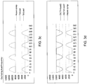
- Fig. 3d shows a situation corresponding to the situation in fig. 3c , using the present invention. As is seen the thruster load is reduced in the opposite direction thus keeping the total load constant.
- Fig. 3e illustrates the corresponding frequency changes as a response to the heave compensation when the load capacity is exceeded in a system according to the known art, and the constant 60Hz frequency in the system according to the invention.
- the invention relates to a system for reducing load and frequency variations in the power distribution of a dynamically positioned vessel.
- the system comprising a consumer load control being connected to at least one power generator and at least one thruster, the consumer load control being adapted to monitor the available power in the system from said at least one power generator and the power consumption from said at least one thruster as well as other power consumers in the system, and a dynamic positioning (DP) unit monitoring the position of the vessel calculating the required thruster capacity for maintaining a predetermined position.
- DP dynamic positioning
- the consumer load control and the DP unit is normally implemented in separate control systems, but can be merged in a common control system if applicable.
- the DP unit is adapted to define an acceptable window for variations in said position and velocity relative to the predetermined position and velocity, and said consumer load control is adapted to adjust the power provided to said thruster in order to reduce total load variations depending on the available power and to the position of the vessel relative to said window.
- the window specifies a tolerable slack that is dependent upon the installed equipment and vessel operation.
- the system comprises available power that has an essentially periodic variation.
- the system being adapted to analyze the variations and thus adjust said vessel position within said window by providing a compensating thrust in order to avoid a static position deviation.
- the analysis includes a step where the amount of load reduced per thruster is sent from the consumer load control 113 to the thrust allocation logic 111. This load is converted to force loss, and the force loss is used as an input to an averaging filter. The output from this filter is used as a feed forward force that is added to the thrust demand for one of the at least one thruster or additional thrusters.
- the system might be adapted to cut the load reduction done by the consumer load control when the vessel is positioned outside said window in order to bring the vessel into the said window.
- the consumer load control might be adapted to receive information about the planned power consumption in other units in the system in order to improve the calculation of the power balance in the system.
- the DP unit might be adapted to adjusting the power consumption in each thruster for adjusting the position of the vessel.
- the consumer load control might be adapted to assign an available power to each thruster in the system based on the adjustments done by the DP unit. If the DP unit requires a power for adjusting the position in at least one thruster is exceeding the available power, an increase in the power is made available for the thruster from the consumer load control.
- the consumer load control is adapted to assign a time varying available power to at least one thruster based on the calculated power consumption in the system.
Landscapes
- Engineering & Computer Science (AREA)
- Aviation & Aerospace Engineering (AREA)
- Radar, Positioning & Navigation (AREA)
- Remote Sensing (AREA)
- Physics & Mathematics (AREA)
- General Physics & Mathematics (AREA)
- Automation & Control Theory (AREA)
- Chemical & Material Sciences (AREA)
- Combustion & Propulsion (AREA)
- Mechanical Engineering (AREA)
- Ocean & Marine Engineering (AREA)
- Supply And Distribution Of Alternating Current (AREA)
Description
- The invention is a method for reducing load and frequency variations induced by variations in heavy consumer load in the power distribution system for a dynamically positioned vessel.
- The present invention relates to a method for reducing load and frequency variations in the high voltage power distribution system while the vessel is controlled by a dynamic positioning (DP) control system or its like by adjusting the available power or torque for the DP controlled thrusters in such a manner that the station keeping conditions are not undermined. The present invention presents way of linking load control and position/velocity control together that has never been done before.
- A dynamic positioning system controls the alongship, athwartship and rotational movement of a vessel, rig, barge or its like. A vessel controlled by a DP control system or its like, shall always strive to fulfill a commanded velocity and position in the axes that are controlled. The DP system controls the vessel movements by the means of thrusters, propellers and rudders. For simplicity and without loss of generality we will use the term thruster for any propulsion means in the rest of the description of the invention. The most common power system today is diesel electric, meaning that the thrusters are propelled by an electric drive and that power is provided by power generators such as diesel-generators, fuel cells, gas-turbines, dual fuel engines, etc. The power is taken from a power plant with many consumers, where the thrusters normally being the dominant one. The power is normally supplied to the power plant by diesel-generators. A high number of diesel generators are normally required to be connected to the power plant in order to keep a stable frequency in the occurrence of consumer load variations from e.g. heave compensation, draw-work, winch and crane. Frequency variations can be fatal for the power system and might lead to black-out, fallout of subsystems, synchronization problems for generators that shall be connected to the power grid and increased fuel consumption. The offshore industry has for many years desired to reduce the number of online generators without risk of frequency variations and potential black-out, but no substantial solution has been provided for this problem. There are several benefits from reducing the number of online generators, such as reduced Nox emission, reduced sooting, reduced fuel consumption, and reduced maintenance on the engines.
- Systems for handling load and power supply to compensate for variations in load are known in the field, such as exemplified in
US2006/111855 where power may be redirected from the thruster, e.g. to heave compensation, andUS2008/284369 where the power supply is controlled based on information about the torque in the motors and e.g. the signals from a dynamic positioning control system. None of these do, however, address the problems that occur due to the interactions between the load control of the power plant and the position/velocity control of the vessel. - Another conventional DP system is known from Raban D., "Integrated Control of Marine Electrical Power Systems (Thesis)".
- The proposed invention solves the problem of reducing the number of online generators without significant frequency variations by the use of the equipment normally installed on a DP controlled vessel, as described in the accompanying claims.
- Thus the invention relates to a system according to
claim 1 including a control law for the dynamic positioning in order to keep the vessel state within given position and velocity frames, a thrust allocation method that allocates thrust so that the given position and velocity frames are kept and a consumer load control that reduces thruster loads in order to compensate for load variations on other consumers in the power distribution system. The invention will be described more in detail below with reference to the accompanying drawings, illustrating the invention by way of examples. -
Fig. 1 illustrates the system according to the invention. -
Fig. 2 illustrates the consumer load control of the system. -
Fig. 3a-e illustrates the dynamic load compensation according to the invention. - The invention is related to a method and system as illustrated in
figure 1 for dynamic load control (DLC) within a dynamic positioning system. The DLC system preferably comprises acontrol law 110, athrust allocation logic 111 and aconsumer load control 113. The objective of thecontrol law 110 is to calculate force demand in each of the controlled axes in order to compensate for deviations between the desired position and velocity received from thesource 100 and the actual vessel position and velocity received from astate observer 101. A maximum limiting force is transmitted to thethrust allocation logic 111. - In addition a
thrust allocation optimization 104 solves a nonlinear optimization problem in order to calculate the thrust amount and direction for each thruster, propeller and rudder controlled by the DP control system such that the thrust demand in each axis given by theforce demand adder 103 is fulfilled. Other constraints for the optimization problem may also apply, e.g. by sensing wind, tension etc 102. The objective for the minimization problem solved by thethrust allocation optimization 104 is normally to minimize the total power usage for the thrusters. - The invention requires a certain amount of thrusters to be available for the DP control system. In the preferred embodiment it comprises at least two freely rotatable thrusters (azimuth thrusters) must be available for DLC. At least a sufficient number of thrusters must be available, so that the remaining thrusters can provide thrust in all the controlled axes. The
thrust allocation logic 111 will set up the objective and the constraints for the optimization problem to be solved by 104. - The objective for the
consumer load control 113 is to calculate the power limit for each thruster such that the total load variations are kept to a minimum. In a normal dynamic positioning system thecontrol law 110 will demand a force to compensate for any deviation from a given position (resp. heading) and velocity (resp. rate of turn) setpoint. In the present invention a tolerance window is implemented for the deviations so that the deviations have to be outside the window before the controller demands a compensating thrust, or the position within the window may be used to decide the necessary applied force. - A number of windows with different sizes may also be and thus from the calculated window sizes for position and velocity deviation we calculate an acceptable force deviation limit. This is fed into the
thrust allocation logic 111. - In addition a dynamic load
compensation command source 105 may be used to provide a desired DLC limit to thethrust allocation logic 111. Thepower plant 106 infigure 1 is connected to the consumer load control and also provides information about the spare power capacity and the frequency of the generators. The power plant may also comprise means for increasing the capacity by activating extra power generators, if available if the spare power capacity is too low or the frequency deviates from the ideal system frequency. - As illustrated in
figure 2 the thrusters and propellers may preferably be separated into two groups by thethrust allocation logic 111. This separation is done in order to have control of the force taken away by the DLC. One group is to be used for dynamic load compensation, and the other is not. All thrusters are used to fulfill the thrust demand from thecontrol law 110. The thrusters in the group not used for DLC shall in addition compensate for the thrust loss caused by the DLC. The amount of load reduced per thruster is sent from theconsumer load control 113 to thethrust allocation logic 111. This load is converted to force loss, and the force loss is used as an input to an averaging filter. The output from this filter is used as a feed forward force that is added to the thrust demand for the thrusters not used by DLC. - After the thrust has been allocated to the thruster in the group for DLC the available DLC load is calculated based on the amount of thrust allocated to the DLC thrusters and the acceptable force deviation limit sent from 110 to 111. The available DLC load is sent to the
consumer load control 113. Theconsumer load control 113 will then limit the load on the thruster drive normally by direct power or torque limitation or by other control means. -
Fig. 3a illustrates the known system on the left using a with a DP system having a thruster allocation system and a consumer load control, where heave compensation affects the load and frequency of the power generators directly. Infig. 3b the system according to the invention is provided with the dynamic load compensation which maintains the vessel position relative to the calculated available window in order to maintain stable and efficient power plant operation in thethrust allocator 111, and controlling the actual load handling and power distribution in theconsumer load control 113, thus obtaining a dynamic load in thethruster drives 107. - In the curves in
fig. 3c which illustrates the known art the lower curve illustrates a situation with a periodic heave compensation (lower curve). The thruster load is maintained at a constant level which leads to a corresponding variation in the total load on the system (upper curve). -
Fig. 3d shows a situation corresponding to the situation infig. 3c , using the present invention. As is seen the thruster load is reduced in the opposite direction thus keeping the total load constant.Fig. 3e illustrates the corresponding frequency changes as a response to the heave compensation when the load capacity is exceeded in a system according to the known art, and the constant 60Hz frequency in the system according to the invention. - To summarize the invention relates to a system for reducing load and frequency variations in the power distribution of a dynamically positioned vessel. The system comprising a consumer load control being connected to at least one power generator and at least one thruster, the consumer load control being adapted to monitor the available power in the system from said at least one power generator and the power consumption from said at least one thruster as well as other power consumers in the system, and a dynamic positioning (DP) unit monitoring the position of the vessel calculating the required thruster capacity for maintaining a predetermined position.
- The consumer load control and the DP unit is normally implemented in separate control systems, but can be merged in a common control system if applicable.
The DP unit is adapted to define an acceptable window for variations in said position and velocity relative to the predetermined position and velocity, and said consumer load control is adapted to adjust the power provided to said thruster in order to reduce total load variations depending on the available power and to the position of the vessel relative to said window. The window specifies a tolerable slack that is dependent upon the installed equipment and vessel operation. - The system comprises available power that has an essentially periodic variation. The system being adapted to analyze the variations and thus adjust said vessel position within said window by providing a compensating thrust in order to avoid a static position deviation. The analysis includes a step where the amount of load reduced per thruster is sent from the
consumer load control 113 to thethrust allocation logic 111. This load is converted to force loss, and the force loss is used as an input to an averaging filter. The output from this filter is used as a feed forward force that is added to the thrust demand for one of the at least one thruster or additional thrusters. - The system might be adapted to cut the load reduction done by the consumer load control when the vessel is positioned outside said window in order to bring the vessel into the said window.
- The consumer load control might be adapted to receive information about the planned power consumption in other units in the system in order to improve the calculation of the power balance in the system.
- The DP unit might be adapted to adjusting the power consumption in each thruster for adjusting the position of the vessel. The consumer load control might be adapted to assign an available power to each thruster in the system based on the adjustments done by the DP unit.
If the DP unit requires a power for adjusting the position in at least one thruster is exceeding the available power, an increase in the power is made available for the thruster from the consumer load control. - The consumer load control is adapted to assign a time varying available power to at least one thruster based on the calculated power consumption in the system.
Claims (8)
- System for reducing load and frequency variations in the power distribution of a dynamically positioned vessel, the system comprising
a consumer load control (113) being connected to at least one power generator and at least one thruster (107), the consumer load control (113) being adapted to monitor the available power in the system from said at least one power generator and the power consumption from said at least one thruster as well as other power consumers in the system, and
a dynamic positioning (DP) unit monitoring the position of the vessel and including a thrust allocation logic (111) calculating the required thruster capacity for maintaining a predetermined position, characterised in that
the DP unit is adapted to define an acceptable window for variations in said position relative to the predetermined position and communicate this to said consumer load control (113), and said consumer load control (113) is adapted to adjust the power provided to said thruster to compensate for load variations on other consumers in the power distribution in order to reduce total load variations depending on the available power and on the position of the vessel relative to said window defined by the dynamic positioning (DP) unit, said consumer load control (113) being further adapted to communicate thruster load reduction to said thrust allocation logic (111), and the thrust allocation logic (111) being adapted to convert the thruster load reduction to a feed forward force, said feed forward force being used for calculating the required thruster capacity. - System according to claim 1, wherein said available power has an essentially periodic variation, the system being adapted to analyze the variations and thus adjust said vessel position within said window by providing a compensating thrust in order to avoid a static position deviation.
- System according to claim 1, wherein the system is adapted to cut the load reduction done by the consumer load control when the vessel is positioned outside said window in order to bring the vessel into the said window.
- System according to claim 1, wherein said consumer load control is adapted to receive information about the planned power consumption in other units in the system.
- System according to claim 1, wherein the DP unit is adapted to adjust the power consumption in each thruster for adjusting the position of the vessel, and the consumer load control being adapted to assign an available power to each thruster in the system.
- System according to claim 5, wherein the DP unit, if the required power for adjusting the position in at least one thruster exceeds the available power, requests an increase in the power made available for the thruster from the consumer load control.
- System according to claim 6, wherein the consumer load control is adapted to assign a time varying available power to at least one thruster.
- System according to any of the previous claims, wherein the thruster load reduction is converted to force loss, the force loss is used as an input to an averaging filter, and an output from said averaging filter is used as said feed forward signal.
Applications Claiming Priority (2)
| Application Number | Priority Date | Filing Date | Title |
|---|---|---|---|
| NO20120344A NO334245B1 (en) | 2012-03-22 | 2012-03-22 | Dynamic load compensation |
| PCT/EP2013/054588 WO2013139609A1 (en) | 2012-03-22 | 2013-03-07 | Dynamic load compensation |
Publications (2)
| Publication Number | Publication Date |
|---|---|
| EP2828718A1 EP2828718A1 (en) | 2015-01-28 |
| EP2828718B1 true EP2828718B1 (en) | 2020-10-07 |
Family
ID=47843281
Family Applications (1)
| Application Number | Title | Priority Date | Filing Date |
|---|---|---|---|
| EP13708147.7A Active EP2828718B1 (en) | 2012-03-22 | 2013-03-07 | Dynamic load compensation |
Country Status (8)
| Country | Link |
|---|---|
| US (1) | US20150032306A1 (en) |
| EP (1) | EP2828718B1 (en) |
| KR (1) | KR102070147B1 (en) |
| CN (1) | CN104254811B (en) |
| DK (1) | DK2828718T3 (en) |
| ES (1) | ES2854324T3 (en) |
| NO (1) | NO334245B1 (en) |
| WO (1) | WO2013139609A1 (en) |
Families Citing this family (9)
| Publication number | Priority date | Publication date | Assignee | Title |
|---|---|---|---|---|
| NO335860B1 (en) | 2013-08-30 | 2015-03-09 | Kongsberg Maritime As | Power Plant Protection |
| NO338463B1 (en) * | 2015-03-20 | 2016-08-22 | Kongsberg Maritime As | Dynamic hybrid control |
| EP3307617B1 (en) * | 2015-06-12 | 2022-01-05 | ABB Oy | Vessel control |
| CN108431712B (en) * | 2015-12-18 | 2021-08-27 | Abb瑞士股份有限公司 | Control system for operating a vehicle |
| WO2018228696A1 (en) * | 2017-06-15 | 2018-12-20 | Abb Schweiz Ag | Controlling marine vessel |
| DE102018118496B3 (en) * | 2018-07-31 | 2020-01-16 | Schottel Gmbh | Procedure for evaluating the influence of shallow water |
| CN109885061B (en) * | 2019-03-14 | 2021-11-23 | 哈尔滨工程大学 | Improved NSGA-II-based dynamic positioning multi-objective optimization method |
| CN114435575B (en) * | 2022-03-01 | 2023-04-11 | 深圳国氢新能源科技有限公司 | Ship hybrid power system, energy management control method, equipment and storage medium |
| EP4438461A1 (en) * | 2023-03-28 | 2024-10-02 | Abb Schweiz Ag | Feasible forces and torque of a vessel |
Family Cites Families (17)
| Publication number | Priority date | Publication date | Assignee | Title |
|---|---|---|---|---|
| IT1276965B1 (en) * | 1994-10-21 | 1997-11-03 | Blohm & Voss Int | DEVICE INDEPENDENT FROM THE MAIN ENGINE, USED AS AN ACTIVE MANEUVERING ORGAN, FOR SHIPS |
| DE10104892A1 (en) * | 2001-02-01 | 2002-08-14 | Siemens Ag | Ship Electric System |
| US6848382B1 (en) * | 2002-12-23 | 2005-02-01 | Joannes Raymond Mari Bekker | Portable dynamic positioning system with self-contained electric thrusters |
| NO320692B1 (en) * | 2002-12-30 | 2006-01-16 | Stiftelsen Det Norske Veritas | Process and system for testing computer-based control and monitoring systems in a vessel via a communication channel |
| NO322007B1 (en) | 2004-11-19 | 2006-08-07 | Marine Cybernetics As | Method and system for testing a dynamic positioning system |
| US20070042916A1 (en) * | 2005-06-30 | 2007-02-22 | Iyer Ramnath N | Methods for improved power transmission performance and compositions therefor |
| US20080167766A1 (en) * | 2006-03-20 | 2008-07-10 | Saravanan Thiyagarajan | Method and Computer Software Code for Optimizing a Range When an Operating Mode of a Powered System is Encountered During a Mission |
| US8788135B2 (en) * | 2006-03-20 | 2014-07-22 | General Electric Company | System, method, and computer software code for providing real time optimization of a mission plan for a powered system |
| US9156477B2 (en) * | 2006-03-20 | 2015-10-13 | General Electric Company | Control system and method for remotely isolating powered units in a vehicle system |
| US7933101B2 (en) * | 2007-02-15 | 2011-04-26 | Aka Information Design | Generator power plant protection system and method |
| GB2449119B (en) | 2007-05-11 | 2012-02-29 | Converteam Technology Ltd | Power converters |
| US7690135B2 (en) * | 2007-09-23 | 2010-04-06 | Technip France | Deep sea mining riser and lift system |
| US7806065B1 (en) * | 2008-10-01 | 2010-10-05 | Thrustmaster of Texas, Inc. | Modular system for fast and easy conversion of anchor moored semi-submersibles to dynamically positioned semis without the need for dry docking, using a diesel electric thruster system |
| US7985108B1 (en) * | 2008-10-01 | 2011-07-26 | Thrustmaster of Texas, Inc. | Modular diesel hydraulic thurster system for dynamically positioning semi submersibles |
| US8706330B2 (en) * | 2008-11-14 | 2014-04-22 | Hybrid Innovation Technologies Llc | Electronic system and method of automating, controlling, and optimizing the operation of one or more energy storage units and a combined serial and parallel hybrid marine propulsion system |
| EP2451041A1 (en) * | 2010-11-03 | 2012-05-09 | Converteam Technology Ltd | Methods of operating dual fed systems |
| US20150252757A1 (en) * | 2012-11-12 | 2015-09-10 | Mcalister Technologies, Llc | Chemical fuel conditioning and activation |
-
2012
- 2012-03-22 NO NO20120344A patent/NO334245B1/en unknown
-
2013
- 2013-03-07 EP EP13708147.7A patent/EP2828718B1/en active Active
- 2013-03-07 WO PCT/EP2013/054588 patent/WO2013139609A1/en not_active Ceased
- 2013-03-07 ES ES13708147T patent/ES2854324T3/en active Active
- 2013-03-07 US US14/379,334 patent/US20150032306A1/en not_active Abandoned
- 2013-03-07 CN CN201380015858.9A patent/CN104254811B/en active Active
- 2013-03-07 DK DK13708147.7T patent/DK2828718T3/en active
- 2013-03-07 KR KR1020147029406A patent/KR102070147B1/en active Active
Non-Patent Citations (1)
| Title |
|---|
| None * |
Also Published As
| Publication number | Publication date |
|---|---|
| WO2013139609A1 (en) | 2013-09-26 |
| CN104254811B (en) | 2017-11-21 |
| KR102070147B1 (en) | 2020-01-28 |
| DK2828718T3 (en) | 2021-01-18 |
| KR20140137006A (en) | 2014-12-01 |
| EP2828718A1 (en) | 2015-01-28 |
| NO20120344A1 (en) | 2013-09-23 |
| CN104254811A (en) | 2014-12-31 |
| US20150032306A1 (en) | 2015-01-29 |
| ES2854324T3 (en) | 2021-09-21 |
| NO334245B1 (en) | 2014-01-20 |
Similar Documents
| Publication | Publication Date | Title |
|---|---|---|
| US20150032306A1 (en) | Dynamic load compensation | |
| EP2856599B1 (en) | Predictive control system | |
| US10170912B2 (en) | Dynamic hybrid control | |
| CN106275412B (en) | Method of adjusting the three-engine power plant of a rotorcraft | |
| CN102791571B (en) | Control the method for mooring marine vessel position | |
| CN106275411A (en) | Regulation is for the method for the power-equipment with three electromotors of rotor blade aircraft | |
| CN107922055B (en) | Apparatus and method for distributing electrical power on board an aircraft with limited available power | |
| CN102707625A (en) | Thrust distribution management-based thrust distribution method for dynamic positioning vessel | |
| SE535979C2 (en) | Method and apparatus for avoiding and attenuating the rolling of a ship | |
| NO20131159A1 (en) | POWER MANAGEMENT IN VESSELS | |
| Veksler et al. | Thrust allocation with power management functionality on dynamically positioned vessels | |
| US20220258861A1 (en) | Drone and method for controlling the attitude thereof | |
| CN113573976A (en) | Method for controlling a hybrid power system for a ship | |
| KR20220159959A (en) | Hybrid Propulsion Systems for Helicopters | |
| EP1648096B1 (en) | Electrical control systems | |
| EP2563650B1 (en) | Steering system for a marine vessel | |
| KR101567880B1 (en) | Power supply apparatur for vessel and method for controlling power of the same | |
| KR20210079734A (en) | Propeller and Rotor Speed Control System of Aircraft with Multiple Power Units | |
| JP3983746B2 (en) | Power management method for pod propulsion ship | |
| CN112645228A (en) | Winch control device and winch system of deep water dynamic positioning crude oil conveying device | |
| CN119637034B (en) | Main and auxiliary power hybrid ship power motor control method, system and storage medium | |
| JPS59102692A (en) | Protective device against overload on thrust generator | |
| Liu et al. | Dynamic thrust allocation of dynamic positioning vessel based on model predictive control | |
| NO20141217A1 (en) | Minimizing power consumption for automatically steered vessels subject to external interference | |
| Murata et al. | Joystick control system for domestic product oil carrier “shige maru” |
Legal Events
| Date | Code | Title | Description |
|---|---|---|---|
| PUAI | Public reference made under article 153(3) epc to a published international application that has entered the european phase |
Free format text: ORIGINAL CODE: 0009012 |
|
| 17P | Request for examination filed |
Effective date: 20140829 |
|
| AK | Designated contracting states |
Kind code of ref document: A1 Designated state(s): AL AT BE BG CH CY CZ DE DK EE ES FI FR GB GR HR HU IE IS IT LI LT LU LV MC MK MT NL NO PL PT RO RS SE SI SK SM TR |
|
| AX | Request for extension of the european patent |
Extension state: BA ME |
|
| DAX | Request for extension of the european patent (deleted) | ||
| 17Q | First examination report despatched |
Effective date: 20160517 |
|
| STAA | Information on the status of an ep patent application or granted ep patent |
Free format text: STATUS: EXAMINATION IS IN PROGRESS |
|
| GRAP | Despatch of communication of intention to grant a patent |
Free format text: ORIGINAL CODE: EPIDOSNIGR1 |
|
| STAA | Information on the status of an ep patent application or granted ep patent |
Free format text: STATUS: GRANT OF PATENT IS INTENDED |
|
| INTG | Intention to grant announced |
Effective date: 20200519 |
|
| GRAS | Grant fee paid |
Free format text: ORIGINAL CODE: EPIDOSNIGR3 |
|
| GRAA | (expected) grant |
Free format text: ORIGINAL CODE: 0009210 |
|
| STAA | Information on the status of an ep patent application or granted ep patent |
Free format text: STATUS: THE PATENT HAS BEEN GRANTED |
|
| AK | Designated contracting states |
Kind code of ref document: B1 Designated state(s): AL AT BE BG CH CY CZ DE DK EE ES FI FR GB GR HR HU IE IS IT LI LT LU LV MC MK MT NL NO PL PT RO RS SE SI SK SM TR |
|
| REG | Reference to a national code |
Ref country code: GB Ref legal event code: FG4D |
|
| REG | Reference to a national code |
Ref country code: AT Ref legal event code: REF Ref document number: 1321828 Country of ref document: AT Kind code of ref document: T Effective date: 20201015 Ref country code: CH Ref legal event code: EP |
|
| REG | Reference to a national code |
Ref country code: IE Ref legal event code: FG4D |
|
| REG | Reference to a national code |
Ref country code: DE Ref legal event code: R096 Ref document number: 602013073076 Country of ref document: DE |
|
| REG | Reference to a national code |
Ref country code: FI Ref legal event code: FGE |
|
| REG | Reference to a national code |
Ref country code: DK Ref legal event code: T3 Effective date: 20210111 |
|
| REG | Reference to a national code |
Ref country code: NL Ref legal event code: FP |
|
| REG | Reference to a national code |
Ref country code: AT Ref legal event code: MK05 Ref document number: 1321828 Country of ref document: AT Kind code of ref document: T Effective date: 20201007 |
|
| PG25 | Lapsed in a contracting state [announced via postgrant information from national office to epo] |
Ref country code: GR Free format text: LAPSE BECAUSE OF FAILURE TO SUBMIT A TRANSLATION OF THE DESCRIPTION OR TO PAY THE FEE WITHIN THE PRESCRIBED TIME-LIMIT Effective date: 20210108 Ref country code: RS Free format text: LAPSE BECAUSE OF FAILURE TO SUBMIT A TRANSLATION OF THE DESCRIPTION OR TO PAY THE FEE WITHIN THE PRESCRIBED TIME-LIMIT Effective date: 20201007 Ref country code: NO Free format text: LAPSE BECAUSE OF FAILURE TO SUBMIT A TRANSLATION OF THE DESCRIPTION OR TO PAY THE FEE WITHIN THE PRESCRIBED TIME-LIMIT Effective date: 20210107 Ref country code: PT Free format text: LAPSE BECAUSE OF FAILURE TO SUBMIT A TRANSLATION OF THE DESCRIPTION OR TO PAY THE FEE WITHIN THE PRESCRIBED TIME-LIMIT Effective date: 20210208 |
|
| REG | Reference to a national code |
Ref country code: LT Ref legal event code: MG4D |
|
| PG25 | Lapsed in a contracting state [announced via postgrant information from national office to epo] |
Ref country code: PL Free format text: LAPSE BECAUSE OF FAILURE TO SUBMIT A TRANSLATION OF THE DESCRIPTION OR TO PAY THE FEE WITHIN THE PRESCRIBED TIME-LIMIT Effective date: 20201007 Ref country code: SE Free format text: LAPSE BECAUSE OF FAILURE TO SUBMIT A TRANSLATION OF THE DESCRIPTION OR TO PAY THE FEE WITHIN THE PRESCRIBED TIME-LIMIT Effective date: 20201007 Ref country code: IS Free format text: LAPSE BECAUSE OF FAILURE TO SUBMIT A TRANSLATION OF THE DESCRIPTION OR TO PAY THE FEE WITHIN THE PRESCRIBED TIME-LIMIT Effective date: 20210207 Ref country code: LV Free format text: LAPSE BECAUSE OF FAILURE TO SUBMIT A TRANSLATION OF THE DESCRIPTION OR TO PAY THE FEE WITHIN THE PRESCRIBED TIME-LIMIT Effective date: 20201007 Ref country code: AT Free format text: LAPSE BECAUSE OF FAILURE TO SUBMIT A TRANSLATION OF THE DESCRIPTION OR TO PAY THE FEE WITHIN THE PRESCRIBED TIME-LIMIT Effective date: 20201007 Ref country code: BG Free format text: LAPSE BECAUSE OF FAILURE TO SUBMIT A TRANSLATION OF THE DESCRIPTION OR TO PAY THE FEE WITHIN THE PRESCRIBED TIME-LIMIT Effective date: 20210107 |
|
| PG25 | Lapsed in a contracting state [announced via postgrant information from national office to epo] |
Ref country code: HR Free format text: LAPSE BECAUSE OF FAILURE TO SUBMIT A TRANSLATION OF THE DESCRIPTION OR TO PAY THE FEE WITHIN THE PRESCRIBED TIME-LIMIT Effective date: 20201007 |
|
| REG | Reference to a national code |
Ref country code: DE Ref legal event code: R097 Ref document number: 602013073076 Country of ref document: DE |
|
| PG25 | Lapsed in a contracting state [announced via postgrant information from national office to epo] |
Ref country code: LT Free format text: LAPSE BECAUSE OF FAILURE TO SUBMIT A TRANSLATION OF THE DESCRIPTION OR TO PAY THE FEE WITHIN THE PRESCRIBED TIME-LIMIT Effective date: 20201007 Ref country code: SK Free format text: LAPSE BECAUSE OF FAILURE TO SUBMIT A TRANSLATION OF THE DESCRIPTION OR TO PAY THE FEE WITHIN THE PRESCRIBED TIME-LIMIT Effective date: 20201007 Ref country code: RO Free format text: LAPSE BECAUSE OF FAILURE TO SUBMIT A TRANSLATION OF THE DESCRIPTION OR TO PAY THE FEE WITHIN THE PRESCRIBED TIME-LIMIT Effective date: 20201007 Ref country code: EE Free format text: LAPSE BECAUSE OF FAILURE TO SUBMIT A TRANSLATION OF THE DESCRIPTION OR TO PAY THE FEE WITHIN THE PRESCRIBED TIME-LIMIT Effective date: 20201007 Ref country code: CZ Free format text: LAPSE BECAUSE OF FAILURE TO SUBMIT A TRANSLATION OF THE DESCRIPTION OR TO PAY THE FEE WITHIN THE PRESCRIBED TIME-LIMIT Effective date: 20201007 Ref country code: SM Free format text: LAPSE BECAUSE OF FAILURE TO SUBMIT A TRANSLATION OF THE DESCRIPTION OR TO PAY THE FEE WITHIN THE PRESCRIBED TIME-LIMIT Effective date: 20201007 |
|
| PLBE | No opposition filed within time limit |
Free format text: ORIGINAL CODE: 0009261 |
|
| STAA | Information on the status of an ep patent application or granted ep patent |
Free format text: STATUS: NO OPPOSITION FILED WITHIN TIME LIMIT |
|
| 26N | No opposition filed |
Effective date: 20210708 |
|
| REG | Reference to a national code |
Ref country code: ES Ref legal event code: FG2A Ref document number: 2854324 Country of ref document: ES Kind code of ref document: T3 Effective date: 20210921 |
|
| REG | Reference to a national code |
Ref country code: DE Ref legal event code: R119 Ref document number: 602013073076 Country of ref document: DE |
|
| PG25 | Lapsed in a contracting state [announced via postgrant information from national office to epo] |
Ref country code: AL Free format text: LAPSE BECAUSE OF FAILURE TO SUBMIT A TRANSLATION OF THE DESCRIPTION OR TO PAY THE FEE WITHIN THE PRESCRIBED TIME-LIMIT Effective date: 20201007 Ref country code: MC Free format text: LAPSE BECAUSE OF FAILURE TO SUBMIT A TRANSLATION OF THE DESCRIPTION OR TO PAY THE FEE WITHIN THE PRESCRIBED TIME-LIMIT Effective date: 20201007 |
|
| REG | Reference to a national code |
Ref country code: CH Ref legal event code: PL |
|
| PG25 | Lapsed in a contracting state [announced via postgrant information from national office to epo] |
Ref country code: SI Free format text: LAPSE BECAUSE OF FAILURE TO SUBMIT A TRANSLATION OF THE DESCRIPTION OR TO PAY THE FEE WITHIN THE PRESCRIBED TIME-LIMIT Effective date: 20201007 |
|
| REG | Reference to a national code |
Ref country code: BE Ref legal event code: MM Effective date: 20210331 |
|
| PG25 | Lapsed in a contracting state [announced via postgrant information from national office to epo] |
Ref country code: DE Free format text: LAPSE BECAUSE OF NON-PAYMENT OF DUE FEES Effective date: 20211001 Ref country code: IE Free format text: LAPSE BECAUSE OF NON-PAYMENT OF DUE FEES Effective date: 20210307 Ref country code: FR Free format text: LAPSE BECAUSE OF NON-PAYMENT OF DUE FEES Effective date: 20210331 Ref country code: CH Free format text: LAPSE BECAUSE OF NON-PAYMENT OF DUE FEES Effective date: 20210331 Ref country code: LI Free format text: LAPSE BECAUSE OF NON-PAYMENT OF DUE FEES Effective date: 20210331 Ref country code: LU Free format text: LAPSE BECAUSE OF NON-PAYMENT OF DUE FEES Effective date: 20210307 |
|
| PG25 | Lapsed in a contracting state [announced via postgrant information from national office to epo] |
Ref country code: IS Free format text: LAPSE BECAUSE OF FAILURE TO SUBMIT A TRANSLATION OF THE DESCRIPTION OR TO PAY THE FEE WITHIN THE PRESCRIBED TIME-LIMIT Effective date: 20210207 |
|
| PG25 | Lapsed in a contracting state [announced via postgrant information from national office to epo] |
Ref country code: BE Free format text: LAPSE BECAUSE OF NON-PAYMENT OF DUE FEES Effective date: 20210331 |
|
| PG25 | Lapsed in a contracting state [announced via postgrant information from national office to epo] |
Ref country code: HU Free format text: LAPSE BECAUSE OF FAILURE TO SUBMIT A TRANSLATION OF THE DESCRIPTION OR TO PAY THE FEE WITHIN THE PRESCRIBED TIME-LIMIT; INVALID AB INITIO Effective date: 20130307 |
|
| P01 | Opt-out of the competence of the unified patent court (upc) registered |
Effective date: 20230515 |
|
| PG25 | Lapsed in a contracting state [announced via postgrant information from national office to epo] |
Ref country code: CY Free format text: LAPSE BECAUSE OF FAILURE TO SUBMIT A TRANSLATION OF THE DESCRIPTION OR TO PAY THE FEE WITHIN THE PRESCRIBED TIME-LIMIT Effective date: 20201007 |
|
| PG25 | Lapsed in a contracting state [announced via postgrant information from national office to epo] |
Ref country code: MK Free format text: LAPSE BECAUSE OF FAILURE TO SUBMIT A TRANSLATION OF THE DESCRIPTION OR TO PAY THE FEE WITHIN THE PRESCRIBED TIME-LIMIT Effective date: 20201007 |
|
| PG25 | Lapsed in a contracting state [announced via postgrant information from national office to epo] |
Ref country code: MT Free format text: LAPSE BECAUSE OF FAILURE TO SUBMIT A TRANSLATION OF THE DESCRIPTION OR TO PAY THE FEE WITHIN THE PRESCRIBED TIME-LIMIT Effective date: 20201007 |
|
| PGFP | Annual fee paid to national office [announced via postgrant information from national office to epo] |
Ref country code: ES Payment date: 20250401 Year of fee payment: 13 |
|
| PG25 | Lapsed in a contracting state [announced via postgrant information from national office to epo] |
Ref country code: TR Free format text: LAPSE BECAUSE OF FAILURE TO SUBMIT A TRANSLATION OF THE DESCRIPTION OR TO PAY THE FEE WITHIN THE PRESCRIBED TIME-LIMIT Effective date: 20201007 |
|
| PGFP | Annual fee paid to national office [announced via postgrant information from national office to epo] |
Ref country code: GB Payment date: 20260327 Year of fee payment: 14 |
|
| PGFP | Annual fee paid to national office [announced via postgrant information from national office to epo] |
Ref country code: DK Payment date: 20260325 Year of fee payment: 14 |
|
| PGFP | Annual fee paid to national office [announced via postgrant information from national office to epo] |
Ref country code: FI Payment date: 20260325 Year of fee payment: 14 Ref country code: IT Payment date: 20260319 Year of fee payment: 14 |
|
| PGFP | Annual fee paid to national office [announced via postgrant information from national office to epo] |
Ref country code: NL Payment date: 20260326 Year of fee payment: 14 |