EP2828448B1 - Anordnung und verfahren zum erzielen einer bewegung durch eine gegendrehung gegenüberliegender endstücke eines bogenförmigen flexiblen elements - Google Patents
Anordnung und verfahren zum erzielen einer bewegung durch eine gegendrehung gegenüberliegender endstücke eines bogenförmigen flexiblen elements Download PDFInfo
- Publication number
- EP2828448B1 EP2828448B1 EP13764542.0A EP13764542A EP2828448B1 EP 2828448 B1 EP2828448 B1 EP 2828448B1 EP 13764542 A EP13764542 A EP 13764542A EP 2828448 B1 EP2828448 B1 EP 2828448B1
- Authority
- EP
- European Patent Office
- Prior art keywords
- arrangement
- flexible member
- flexible
- platform
- columnar structure
- Prior art date
- Legal status (The legal status is an assumption and is not a legal conclusion. Google has not performed a legal analysis and makes no representation as to the accuracy of the status listed.)
- Active
Links
Images




Classifications
-
- E—FIXED CONSTRUCTIONS
- E04—BUILDING
- E04G—SCAFFOLDING; FORMS; SHUTTERING; BUILDING IMPLEMENTS OR AIDS, OR THEIR USE; HANDLING BUILDING MATERIALS ON THE SITE; REPAIRING, BREAKING-UP OR OTHER WORK ON EXISTING BUILDINGS
- E04G3/00—Scaffolds essentially supported by building constructions, e.g. adjustable in height
- E04G3/28—Mobile scaffolds; Scaffolds with mobile platforms
-
- A—HUMAN NECESSITIES
- A63—SPORTS; GAMES; AMUSEMENTS
- A63B—APPARATUS FOR PHYSICAL TRAINING, GYMNASTICS, SWIMMING, CLIMBING, OR FENCING; BALL GAMES; TRAINING EQUIPMENT
- A63B27/00—Apparatus for climbing poles, trees, or the like
-
- A—HUMAN NECESSITIES
- A01—AGRICULTURE; FORESTRY; ANIMAL HUSBANDRY; HUNTING; TRAPPING; FISHING
- A01M—CATCHING, TRAPPING OR SCARING OF ANIMALS; APPARATUS FOR THE DESTRUCTION OF NOXIOUS ANIMALS OR NOXIOUS PLANTS
- A01M31/00—Hunting appliances
- A01M31/02—Shooting stands
-
- F—MECHANICAL ENGINEERING; LIGHTING; HEATING; WEAPONS; BLASTING
- F16—ENGINEERING ELEMENTS AND UNITS; GENERAL MEASURES FOR PRODUCING AND MAINTAINING EFFECTIVE FUNCTIONING OF MACHINES OR INSTALLATIONS; THERMAL INSULATION IN GENERAL
- F16H—GEARING
- F16H19/00—Gearings comprising essentially only toothed gears or friction members and not capable of conveying indefinitely-continuing rotary motion
- F16H19/02—Gearings comprising essentially only toothed gears or friction members and not capable of conveying indefinitely-continuing rotary motion for interconverting rotary or oscillating motion and reciprocating motion
- F16H19/025—Gearings comprising essentially only toothed gears or friction members and not capable of conveying indefinitely-continuing rotary motion for interconverting rotary or oscillating motion and reciprocating motion comprising a friction shaft
-
- A—HUMAN NECESSITIES
- A01—AGRICULTURE; FORESTRY; ANIMAL HUSBANDRY; HUNTING; TRAPPING; FISHING
- A01G—HORTICULTURE; CULTIVATION OF VEGETABLES, FLOWERS, RICE, FRUIT, VINES, HOPS OR SEAWEED; FORESTRY; WATERING
- A01G23/00—Forestry
- A01G23/02—Transplanting, uprooting, felling or delimbing trees
- A01G23/08—Felling trees
-
- Y—GENERAL TAGGING OF NEW TECHNOLOGICAL DEVELOPMENTS; GENERAL TAGGING OF CROSS-SECTIONAL TECHNOLOGIES SPANNING OVER SEVERAL SECTIONS OF THE IPC; TECHNICAL SUBJECTS COVERED BY FORMER USPC CROSS-REFERENCE ART COLLECTIONS [XRACs] AND DIGESTS
- Y10—TECHNICAL SUBJECTS COVERED BY FORMER USPC
- Y10T—TECHNICAL SUBJECTS COVERED BY FORMER US CLASSIFICATION
- Y10T74/00—Machine element or mechanism
- Y10T74/18—Mechanical movements
- Y10T74/18056—Rotary to or from reciprocating or oscillating
Definitions
- the present invention relates to an arrangement according to the opening part of claim 1 and a method according to the opening part of claim 10.
- the present invention relates to an arrangement for imparting motion through counter-rotation of opposing terminations of a flexible, elastic member and, more particularly, to imparting motion to the flexible member with respect to, for example, a columnar structure so as to use the flexible member to raise/lower attached components along the longitudinal axis of the columnar structure.
- Prior art arrangements that are designed for use with irregularly-shaped columnar structures (for example, trees) are configured to concentrate a load force upon a minimal number of points of contact. As a result, the traction associated with the arrangement is limited and may result in damaging the tree or other such structure.
- the arrangements used in an urban environment use separate support systems and require a large operating footprint (including a utility truck, for example), often resulting in street traffic being shut down in an area surrounding the work location.
- the present invention describes an arrangement for imparting translational movement of a load with respect to a columnar structure that takes the form of at least one flexible elastic member (e.g., bungee cord) that is disposed to surround a portion of the structure.
- a platform (or any other suitable type of load container) is coupled to the opposing ends of the flexible elastic member.
- the platform is used to support the load and the ends of the flexible member are coupled to the platform in a manner such that the ends are free to rotate.
- the application of counter-rotational forces to these opposing end terminations will impart a tension to the flexible elastic member that ultimately causes the flexible member to flip over to relieve the tension.
- the flexible member will continue to flip, and progress in translational movement along the columnar structure.
- the application of counter-rotational forces (torque) to the opposing ends of a flexible member that is positioned to surround at least a portion of a columnar structure creates a helical torsion moment along the arcuate (i.e., arched) shape of the flexible member.
- this helical torsion moment then translates into linear movement of the flexible member (with respect to the longitudinal axis of the columnar member).
- FIG. 1 is a basic, simplified diagram illustrating the principles of the present invention.
- a flexible member 10 is disposed to surround a portion of a columnar structure 12.
- Flexible member 10 may comprise, for example, a bungee cord, a section of rope (or other fibrous material) with sufficient elasticity to react to a torque moment, a chain-like segmented linkage or a spring - again, where the linkage or spring has sufficient elasticity to react to a torque moment.
- a spring may be formed in arcuate form, as shown in FIG. 1 . Regardless of the specific material choice for flexible member 10, its important quality is to exhibit a torque moment rotation reaction. While not specifically shown in FIG.
- flexible member 10 is to be disposed in a tensioned state with respect to columnar structure 12. That is, some type of fixturing (e.g., ratchet, engagement, etc.) is created between end terminations 14 and 16 of flexible member 10 in order to hold member 10 in place along columnar structure 12.
- fixturing e.g., ratchet, engagement, etc.
- a clockwise rotational force F CW is applied to first end termination 14, while a counterclockwise rotation force F CCW is simultaneously applied to second end termination 16.
- These rotational forces will continue to build up potential energy along the lateral extent of flexible member 10 (that is, along its radius of curvature R), as the force is continued to be applied.
- the torsion moment of flexible member 10 will be overcome, causing flexible member 10 to "flip", converting the stored potential energy into kinetic energy in the form of translational movement of flexible member 10 with respect to longitudinal axis A of columnar structure 12.
- this inventive arrangement provides a natural "brake” in terms of preventing flexible member 10 from slipping downward in the absence of the application of counter-rotational forces on the end terminations of the flexible member.
- FIG. 2 is a top view of the arrangement of FIG. 1 , illustrating the particular forces that are at work in providing the translational movement of a flexible member with respect to a columnar structure.
- FIG. 2 shows a large contact area between flexible member 10 and columnar structure 12, indicated by the shaded portion 11 of flexible member 10.
- Distributed inward tension force F in as shown along this contact area 11 is the result of the linear tensions created by holding flexible member 10 in a tensioned state with respect to columnar structure 12, as mentioned above.
- This linear tension is shown as F LIN at end terminations 14 and 16. Indeed, this linear tension is the force that holds flexible member 10 in place in the absence of the application of counter-rotational forces.
- the linear tension will act as a "braking" force and maintain the position of flexible member 10 along columnar structure 12.
- distributed force F in when rotated, becomes the drive force that results in "flipping" flexible member 10 and allowing for the translational movement of flexible member 10 with respect to columnar structure 12.
- FIGs. 3 and 4 further illustrate the utilization of these forces along flexible member 10 to cause its movement with respect to columnar structure 12.
- FIG. 3 illustrates flexible member 10 in a "relaxed" state in position with respect to columnar structure 12. This may be the state immediately after flexible member 10 has flipped, or its initial position before any counter-rotational forces have been applied.
- Line 36 along flexible member 10 defines its stress line, and shows the line to be orthogonal to columnar structure 12; indicative of the presence of only the linear tension forces on flexible member 10.
- FIG. 4 shows the distortion change in stress line 36 when forces F CW and F CCW are applied to end terminations 14, 16 of flexible member 10.
- the arched central region of stress line 36 illustrates the increase of inward tension force F in , where it encounters resistance against columnar structure 12.
- This distortion shows evenly-distributed and smoothed potential energy storage throughout the arch, which minimizes the peak torque force required to move flexible member 10 along columnar structure 12 and ultimately allows for the torsion moment to be overcome, releasing the potential energy and causing flexible member 10 to flip and move.
- FIG. 1 illustrates columnar structure 12 as being disposed in a vertical orientation
- columnar structure 12 may be disposed in a horizontal orientation, with flexible member 10 controlled to move either left or right by the application of counter-rotational forces.
- FIG. 5 illustrates this embodiment of the present invention.
- a counterclockwise rotational force F ccw is applied to first end termination 14 and a clockwise rotational force F cw is applied to second end termination 16, resulting in columnar structure 120 moving to the right with respect to flexible member 10.
- relative motion between the two elements (flexible member and columnar structure) will occur, where either element may actually be in motion.
- other orientations of columnar structure 12 e.g., at 45° with respect to the horizon
- columnar structure 120 takes the form of a squared-off beam (as opposed to the rounded, cylindrical profile of columnar structure 12 of FIG. 1 ). Indeed, it is to be understood that the columnar structure may take a variety of forms, including "natural"/irregular columnar structures such as trees.
- FIG. 6 illustrates, in conceptual form, an embodiment of the present invention as used to raise a load in an upward direction along a columnar structure taking the form of a pole 122.
- This is an isometric view, showing an exemplary arrangement for using flexible member 10 to raise a platform 20 upward along pole 122.
- FIG. 7 is a side view of platform 20, taken along line 7-7 of FIG. 6
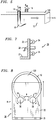
- FIG. 8 is a front view of platform 20, taken along line 8-8 of FIG. 6 .
- platform 20 includes a floor portion 21 and a sidewall portion 22.
- Platform 20 further comprises at least one translation member (in this case a pair of wheels 24, 26) attached to the backside of sidewall portion 22 so as to rest against pole 122.
- translational movement of platform 20 with respect to pole 122 is provided by a pair of crank handles 28, 30 that are attached (through the thickness of sidewall 22) to end terminations 14,16 of flexible member 10.
- Crank handles 28, 30 are used to impart the counter-rotational forces to flexible member 10, providing the translation movement as described above.
- crank handles 28, 30 are rotated “inward” (shown by arrows “A”, with crank handle 30 rotating clockwise and crank handle 28 rotating counterclockwise), the imparted tension to flexible member 10 will cause member 10 to "flip” upward, raising platform 20 as indicated by the “up” arrow in FIG. 8 .
- crank handles 28, 30 are rotated “outward” (shown by arrows “B”, with crank handle 30 rotating counterclockwise and crank handle 38 rotating clockwise)
- the imparted tension to flexible member 10 will cause member 10 to "flip” downward, lowering platform 20 as indicated by the "down” arrow in FIG. 8 .
- FIGs. 6-8 illustrates the use of a pair of crank handles to impart this counter-rotational force
- any other suitable drive mechanism may be used.
- a remotely-controlled motor may be used to create and provide the desired counter-rotational forces to end terminations 14, 16 of flexible member 10.
- a tether-driven arrangement may also be used in place of a remote configuration.
- the scope of the present invention is understood to not be limited by the arrangement used to apply the force to the flexible member.
- FIGs. 6 - 8 illustrates the use of a single flexible member to create the relative motion between the platform and the pole
- other configurations of the present invention may use a multiple number of flexible members that work in combination to move loads.
- the tandem arrangement of multiplex flexible members can take a variety of different forms, including having a multiple number of flexible members attached to a single platform sidewall or each flexible member attached to a separate platform sidewall, or any combination thereof.
- FIG. 9 is a side view of an exemplary set of three flexible members 10-1, 10-2 and 10-3, as positioned on pole 122, where these three members may be attached to a single platform sidewall (not shown) and operated simultaneously to provide a larger, stronger force for translational movement. Additionally, the use of multiple flexible members is considered to improve the safety of the structure, since if any one flexible member breaks, the remaining members are able to continue to support the attached load. It is contemplated that a single pair of counter-rotational forces may be used with this embodiment, with the single pair used to simultaneously rotate all three flexible members. However, it is also possible to individually control each flexible member with its own pair of counter-rotational forces.
- one feature of the arrangement of the present invention is its ability to provide translation movement along an oddly-shaped columnar structure (such as a tree).
- a tree, or any kind of pole may include protuberances along its surface of many kinds (i.e., a knot in a tree, a directional plate screwed in place on a pole, etc.).
- the nature of the "flip" movement of the flexible member of the present invention, in conjunction with the elasticity of the flexible member allows it to accommodate the presence of these irregularities and continue with its translational movement.
- FIG. 10 illustrates this aspect of the present invention, showing the upward movement of flexible member 10 along a pole 124 that includes an outward bulge section 126.
- a clockwise force is applied to end termination 14 of flexible member 10 and a counterclockwise force is applied to end termination 16 of flexible member 10, which will initially result in flexible member 10 "flipping" from position I to position II.
- all of the kinetic energy has been used, and the application of additional clockwise/counterclockwise force will result in flexible member 10 again flipping upward into position III. Since flexible member 10 also had to expand to accommodate the presence of bulge 126, some of the energy was expended in this movement, and the actual lateral translation of the attached load (not shown) is slightly less than that associated with the first movement from position I to position II.
- the counter-rotational forces are applied to flexible member 10, where in this case an additional amount of force may be necessary to assist in overcoming the additional barrier to movement created by the presence of bulge 126. At some point, however, a sufficient amount of force will be built up within flexible member 10, and it will flip from position III to position IV. Thereafter, the translation movement proceeds unimpeded.
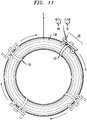
- FIG. 11 illustrates yet another embodiment of the present invention, in this case where the columnar structure takes on the form of a toroid instead of a linear structure.
- the application of counter-rotational forces to end terminations 14, 16 of flexible member 10 will translate platform 20 around the circular configuration of toroidal structure 130.
- the movement of platform 20 to various locations is shown in phantom in FIG. 11 .
- the use of counter-rotational forces applied to a flexible member results in imparting motion of an attached load in a variety of different embodiments.
- the arrangement of the present invention is a fundamentally new and basic type of drive technology.
- any type of attached devices such as the "platform” described above
- the subject matter of the present invention finds uses in moving many types of loads within arrangements such as, but not limited to, portable and fixed elevators, lift platforms, pole and pipeline construction and maintenance, multi-directional platforms, replacements for stairways, scaffolding, ladders, tree climbers, etc.
Landscapes
- Engineering & Computer Science (AREA)
- Life Sciences & Earth Sciences (AREA)
- Architecture (AREA)
- General Engineering & Computer Science (AREA)
- General Health & Medical Sciences (AREA)
- Physical Education & Sports Medicine (AREA)
- Mechanical Engineering (AREA)
- Insects & Arthropods (AREA)
- Pest Control & Pesticides (AREA)
- Wood Science & Technology (AREA)
- Zoology (AREA)
- Environmental Sciences (AREA)
- Health & Medical Sciences (AREA)
- Structural Engineering (AREA)
- Civil Engineering (AREA)
- Ladders (AREA)
- Pivots And Pivotal Connections (AREA)
- Transmission Devices (AREA)
- Refuge Islands, Traffic Blockers, Or Guard Fence (AREA)
- Tents Or Canopies (AREA)
- Toys (AREA)
- Vibration Prevention Devices (AREA)
- Catching Or Destruction (AREA)
Claims (10)
- Anordnung zum Erzielen einer translatorischen Bewegung einer Last in Bezug auf eine mit derselben verbundene Struktur, wobei die Anordnung Folgendes umfasst:wenigstens ein flexibles elastisches Element (10), das so angeordnet ist, dass es einen Teil der Struktur umgibt, wobei das flexible elastische Element als gegenüberliegende Endstücke (14, 16) aufweisend festgelegt ist, undeine Plattform (20), die mit den gegenüberliegenden Enden (14, 16) des flexiblen elastischen Elements (10) gekoppelt ist und zum Abstützen der Last dient, dadurch gekennzeichnet, dass die Plattform (20) ferner Mittel (28, 30) zum Übermitteln von gegendrehenden Kräften an die gegenüberliegenden Endstücke (14, 16) des flexiblen elastischen Elements (10) umfasst, die ausreichen, um eine Zugspannung an das flexible elastische Element (10) zu übermitteln, die abgebaut wird, indem bewirkt wird, dass sich das flexible elastische Element (10) umdreht und sich entlang der Struktur verschiebt.
- Anordnung nach Anspruch 1, wobei das wenigstens eine flexible elastische Element ein einzelnes mit der Plattform gekoppeltes flexibles elastisches Element (10) umfasst.
- Anordnung nach Anspruch 1, wobei das wenigstens eine flexible elastische Element eine Vielzahl von flexiblen elastischen Elementen (10-1, 10-2, 10-3) umfasst, die parallel angeordnet sind.
- Anordnung nach Anspruch 3, wobei jedes flexible elastische Element (10-1, 10-2, 10-3) zum Aufnehmen von gegendrehenden Kräften separat gesteuert wird.
- Anordnung nach Anspruch 3, wobei die Vielzahl von flexiblen elastischen Elementen (10-1, 10-2, 10-3) zum Aufnehmen von gegendrehenden Kräften gemeinsam gesteuert wird.
- Anordnung nach Anspruch 1, wobei die gegenüberliegenden Endstücke (14, 16) wenigstens eines flexiblen Elements (10) so angeordnet sind, dass sie eine lineare Zugspannung in Bezug auf die säulenförmige Struktur erzeugen.
- Anordnung nach Anspruch 6, wobei die lineare Zugspannung ausreichend ist, um die Position des wenigstens einen flexiblen Elements (10) in Bezug auf die säulenförmige Struktur bei Abwesenheit gegendrehender Kräfte aufrechtzuerhalten.
- Anordnung nach Anspruch 1, wobei die Anordnung ferner ein passives translatorisches Element (24, 26) umfasst, das mit der Plattform (20) gekoppelt ist, um bei der Bewegung der Plattform in Bezug auf die Struktur mitzuwirken.
- Anordnung nach Anspruch 8, wobei das passive translatorische Element ein oder mehrere Räder (24, 26) umfasst, die an der Plattform (20) angebracht sind.
- Verfahren zum Bewegen einer Last entlang einer säulenförmigen Struktur, wobei das Verfahren folgende Schritte umfasst:Platzieren eines flexiblen Elements (10) auf eine solche Weise, dass es einen Teil der säulenförmigen Struktur (12) umgibt, und Aufrechterhalten von gegenüberliegenden Endstücken (14, 16) des flexiblen Elements (10) in einem linear gespannten Zustand (FLIN), um in Bezug auf die säulenförmige Struktur fest an Ort und Stelle zu verbleiben,Anbringen einer die Last abstützenden Plattform (20) an den gegenüberliegenden Endstücken (14, 16) des flexiblen Elements (10) auf eine solche Weise, dass die gegenüberliegenden Endstücke (14, 16) frei drehbar bleiben, dadurch gekennzeichnet, dass das Verfahren ferner folgenden Schritt umfasst:
Übermitteln von gegendrehenden Kräften (F CCW , F CW ) an die gegenüberliegenden Endstücke (14, 16) des flexiblen Elements (10), um ein Drehmoment entlang dem flexiblen Element (10) zu erzeugen und letztendlich zu bewirken, dass das flexible Element (10) das Drehmoment überwindet und sich umdreht, um sich entlang der säulenförmigen Struktur zu verschieben.
Applications Claiming Priority (3)
| Application Number | Priority Date | Filing Date | Title |
|---|---|---|---|
| US201261612348P | 2012-03-18 | 2012-03-18 | |
| US13/782,766 US9320941B2 (en) | 2012-03-18 | 2013-03-01 | Arrangement for imparting motion through counter-rotation of opposing end terminations of arched flexible member |
| PCT/US2013/029250 WO2013142047A1 (en) | 2012-03-18 | 2013-03-06 | Arrangement for imparting motion through counter-rotation of opposing terminations of arched flexible member |
Publications (3)
| Publication Number | Publication Date |
|---|---|
| EP2828448A1 EP2828448A1 (de) | 2015-01-28 |
| EP2828448A4 EP2828448A4 (de) | 2017-03-22 |
| EP2828448B1 true EP2828448B1 (de) | 2018-05-30 |
Family
ID=49156434
Family Applications (1)
| Application Number | Title | Priority Date | Filing Date |
|---|---|---|---|
| EP13764542.0A Active EP2828448B1 (de) | 2012-03-18 | 2013-03-06 | Anordnung und verfahren zum erzielen einer bewegung durch eine gegendrehung gegenüberliegender endstücke eines bogenförmigen flexiblen elements |
Country Status (9)
| Country | Link |
|---|---|
| US (1) | US9320941B2 (de) |
| EP (1) | EP2828448B1 (de) |
| JP (1) | JP6195892B2 (de) |
| CN (1) | CN104169507B (de) |
| BR (1) | BR112014022675B1 (de) |
| CA (1) | CA2867634C (de) |
| IN (1) | IN2014DN07257A (de) |
| RU (1) | RU2614995C2 (de) |
| WO (1) | WO2013142047A1 (de) |
Families Citing this family (4)
| Publication number | Priority date | Publication date | Assignee | Title |
|---|---|---|---|---|
| US10869433B1 (en) | 2016-02-09 | 2020-12-22 | Rotor Blade | Tree trimming apparatus and method |
| US10624596B2 (en) | 2016-11-23 | 2020-04-21 | Mobius Imaging, Llc | Cantilevered x-ray CT system for multi-axis imaging |
| US11311779B2 (en) * | 2018-05-02 | 2022-04-26 | Take It, LLC | Adjustable climbing stand |
| CN121130390B (zh) * | 2025-11-10 | 2026-03-03 | 昌鸿控股集团有限公司 | 一种带有防坠落结构的电力攀爬装置及其使用方法 |
Family Cites Families (46)
| Publication number | Priority date | Publication date | Assignee | Title |
|---|---|---|---|---|
| US2654638A (en) * | 1951-04-13 | 1953-10-06 | Robert A Elliott | Pole climbing device |
| SE203830C1 (sv) | 1963-04-19 | 1966-04-26 | Aktiebolaget Partner | Anordning för transport av bearbetande eller ytbehandlande apparater över ytan på långsträckta föremål med i huvudsak rund tvärsektion |
| US3434610A (en) * | 1967-08-03 | 1969-03-25 | Wanskuck Co | Feeding apparatus for tubes,rods and the like |
| US3520383A (en) | 1968-10-29 | 1970-07-14 | Willi Loock | Apparatus for climbing pole-like objects |
| FR2294566A1 (fr) * | 1974-12-11 | 1976-07-09 | Mugnaini Fernando | Dispositif elevateur permettant d'elever un operateur le long d'un poteau de soutien pour lignes electriques, etc |
| DE2617769A1 (de) * | 1976-04-23 | 1977-11-03 | Peter Sprenger Fa | Vorrichtung zum befahren von masten u.dgl. |
| US4060149A (en) * | 1976-11-17 | 1977-11-29 | Henley James C | Conveyer apparatus |
| JPS5825164U (ja) * | 1981-08-12 | 1983-02-17 | 山田機械工業株式会社 | 登「はん」具 |
| US4428459A (en) | 1982-11-08 | 1984-01-31 | Total Shooting Systems, Inc. | Tree stand |
| US4595076A (en) | 1985-09-04 | 1986-06-17 | Gober Benjamin G | Tree climbing apparatus |
| US4802552A (en) | 1987-07-28 | 1989-02-07 | Loggy Bayou Industries | Combined climbing and hang-on tree stand with optional climbing aid |
| US4890694A (en) | 1987-07-28 | 1990-01-02 | Loggy Bayou Industries | Combined climbing and hang-on tree stand with optional climbing aid |
| US5097925A (en) | 1990-06-14 | 1992-03-24 | George T. Walker, Jr. | Tree walker |
| US5086874A (en) | 1990-09-10 | 1992-02-11 | Bill Treants | Tree climbing apparatus |
| US5152369A (en) * | 1991-09-10 | 1992-10-06 | Mori Nakaoka | Apparatus and method for hoisting a platform adjacent a scaffolding |
| US5379861A (en) | 1992-01-08 | 1995-01-10 | Amacker; Joseph A. | Automatically adjustable tree climbing stand |
| US5141074A (en) | 1992-02-24 | 1992-08-25 | Ontario Hydro | Lineman's pole strap assembly |
| JP2943116B2 (ja) * | 1994-05-30 | 1999-08-30 | 林野庁森林総合研究所長 | 樹冠部昇降装置 |
| US5584358A (en) | 1995-06-07 | 1996-12-17 | Stone; Charles E. | Climbing tree stand |
| US5647454A (en) | 1995-06-19 | 1997-07-15 | Fehr; Daniel D. | Fast tract tree climbling apparatus |
| US5692582A (en) * | 1996-01-04 | 1997-12-02 | Lindemood; Norman R. | Upright column climbing device |
| US5642789A (en) | 1996-01-05 | 1997-07-01 | Maxwell; James Clifford | Cam adjustable climbing tree stand |
| US6267202B1 (en) | 1998-10-09 | 2001-07-31 | Rick J. Nelson | Elevation platform |
| US6264000B1 (en) | 1999-01-29 | 2001-07-24 | Usl Products Incorporated | Tree stand and climbing devices |
| JP4437268B2 (ja) * | 1999-04-28 | 2010-03-24 | 株式会社パボット技研 | コイルローラー |
| US6481529B1 (en) | 2000-10-13 | 2002-11-19 | Barry Kent Voorhies | Climbing tree stand |
| US7156206B2 (en) | 2001-08-08 | 2007-01-02 | Prejean L Wayne | Climbing tree stand with supplemental bracing members |
| US6595325B2 (en) | 2001-08-31 | 2003-07-22 | Bruce E. Ulrich | Tree stand with level adjustment |
| US6698549B2 (en) | 2002-03-15 | 2004-03-02 | Buckshot, Inc. | Climbing tree stand |
| US20030178251A1 (en) | 2002-03-21 | 2003-09-25 | Hewitt Mark E. | Self-elevating tree stand |
| US6644438B1 (en) | 2002-09-06 | 2003-11-11 | Scepter Corporation | Pole climbing and safety device |
| US20050072631A1 (en) | 2003-10-07 | 2005-04-07 | Tracey Robert B. | Climbing tree stand |
| US7287623B2 (en) | 2003-10-15 | 2007-10-30 | Graham Sr Thomas E | Adjustable tree stand with power drive |
| NZ548485A (en) * | 2003-12-30 | 2009-06-26 | Pp Energy Aps | Device for enabling access to a structure above ground level |
| US6959786B2 (en) | 2004-02-17 | 2005-11-01 | Craft Roger A | Slope compensating tree stand |
| US7497302B2 (en) | 2004-06-08 | 2009-03-03 | Curtis Jason Boice | Adjustable tensile member for a climbing stand |
| US7552798B2 (en) | 2004-08-27 | 2009-06-30 | Robert John Swierski | Column climbing device and associated method of use |
| US7802653B2 (en) | 2005-01-14 | 2010-09-28 | Louk John M | Adjustable tree stand |
| CN2920319Y (zh) * | 2006-07-18 | 2007-07-11 | 林超 | 攀登式爬树架 |
| US7823694B2 (en) | 2007-05-03 | 2010-11-02 | Motes Outdoor Equipment, Llc | Motorized climbing hunting stand |
| US8021098B2 (en) | 2007-06-20 | 2011-09-20 | J.S. Redpath Limited | Portable raise climbing system |
| CN201158933Y (zh) * | 2007-12-27 | 2008-12-03 | 上海市第七建筑有限公司 | 一种高层外挑结构维修脚手架装置 |
| WO2010112032A1 (en) * | 2009-04-02 | 2010-10-07 | Lm Glasfiber A/S | Work platform |
| TWM382720U (en) | 2010-02-10 | 2010-06-21 | bai-feng Dong | Movable hunting device |
| CN101818564B (zh) * | 2010-06-04 | 2011-10-05 | 中建三局建设工程股份有限公司 | 可调节式挂架体系 |
| US8579085B2 (en) * | 2010-12-29 | 2013-11-12 | Sky Climber Llc | Suspended access chair with rescue system |
-
2013
- 2013-03-01 US US13/782,766 patent/US9320941B2/en active Active
- 2013-03-06 BR BR112014022675-0A patent/BR112014022675B1/pt active IP Right Grant
- 2013-03-06 EP EP13764542.0A patent/EP2828448B1/de active Active
- 2013-03-06 RU RU2014136931A patent/RU2614995C2/ru active
- 2013-03-06 CN CN201380014470.7A patent/CN104169507B/zh active Active
- 2013-03-06 JP JP2015500460A patent/JP6195892B2/ja active Active
- 2013-03-06 CA CA2867634A patent/CA2867634C/en active Active
- 2013-03-06 WO PCT/US2013/029250 patent/WO2013142047A1/en not_active Ceased
-
2014
- 2014-08-28 IN IN7257DEN2014 patent/IN2014DN07257A/en unknown
Non-Patent Citations (1)
| Title |
|---|
| None * |
Also Published As
| Publication number | Publication date |
|---|---|
| CN104169507B (zh) | 2016-06-15 |
| IN2014DN07257A (de) | 2015-04-24 |
| BR112014022675A2 (de) | 2017-06-20 |
| HK1203585A1 (zh) | 2015-10-30 |
| US9320941B2 (en) | 2016-04-26 |
| CA2867634A1 (en) | 2013-09-26 |
| WO2013142047A1 (en) | 2013-09-26 |
| RU2014136931A (ru) | 2016-05-20 |
| CN104169507A (zh) | 2014-11-26 |
| CA2867634C (en) | 2019-06-11 |
| US20130239711A1 (en) | 2013-09-19 |
| BR112014022675B1 (pt) | 2021-11-03 |
| RU2614995C2 (ru) | 2017-04-03 |
| JP2015513053A (ja) | 2015-04-30 |
| EP2828448A4 (de) | 2017-03-22 |
| EP2828448A1 (de) | 2015-01-28 |
| JP6195892B2 (ja) | 2017-09-13 |
Similar Documents
| Publication | Publication Date | Title |
|---|---|---|
| ES2369925T3 (es) | Dispositivo para erigir una torre de una instalación de energía eólica compuesta de segmentos de torre individuales. | |
| CA2867634C (en) | Arrangement for imparting motion through counter-rotation of opposing terminations of arched flexible member | |
| CN104781181A (zh) | 用于组装结构的装置和方法 | |
| ES2736723T3 (es) | Sistema para el montaje/desmontaje de palas en aerogeneradores | |
| KR101869685B1 (ko) | 타워크레인 텔레스코핑 장치 | |
| CN114561878B (zh) | 一种拱肋侧向平衡转体施工方法 | |
| BR102016025134A2 (pt) | Wind turbine assembly system and associated method | |
| EP3558856A1 (de) | Anordnung zum drehen einer hängenden last | |
| EP3911592B1 (de) | Hänge-laufkrananordnung | |
| US20130089405A1 (en) | Flexible Articulated Jib Arm | |
| CN212423327U (zh) | 一种履带式攀爬机器人 | |
| CN205820800U (zh) | 可实现无脚手架搭设模板架的液压升降装置 | |
| CN108316147A (zh) | 一种支索装置 | |
| ES2866524T3 (es) | Sistema y método de instalación y desmontaje de vigas maestras | |
| US20180362301A1 (en) | Suspension motion-resisting dynamic system and suspension active dynamic carrier module | |
| HK1203585B (en) | Device for imparting motion through counter-rotation of opposing terminations of arched flexible member | |
| EP3326959B1 (de) | Hebeanordnung für einen in elemente unterteilter mast und verfahren zur montage, demontage und wartung eines mastes | |
| CN105804475B (zh) | 一种用于高压输电线路的铁塔 | |
| CN117284967A (zh) | 一种用于狭小空间内的整体提升系统 | |
| CN106006299A (zh) | 一种电动升降梯 | |
| CN218581230U (zh) | 一种建筑工程安全防护装置 | |
| CN203531497U (zh) | 多功能旋转抱杆 | |
| CN216687081U (zh) | 一种可实现起重机吊重空中水平移动、扭转及防摇的装置 | |
| US20210331900A1 (en) | Roof-Mounted Building Access System | |
| CN212836948U (zh) | 一种升降舞台 |
Legal Events
| Date | Code | Title | Description |
|---|---|---|---|
| PUAI | Public reference made under article 153(3) epc to a published international application that has entered the european phase |
Free format text: ORIGINAL CODE: 0009012 |
|
| 17P | Request for examination filed |
Effective date: 20140917 |
|
| AK | Designated contracting states |
Kind code of ref document: A1 Designated state(s): AL AT BE BG CH CY CZ DE DK EE ES FI FR GB GR HR HU IE IS IT LI LT LU LV MC MK MT NL NO PL PT RO RS SE SI SK SM TR |
|
| AX | Request for extension of the european patent |
Extension state: BA ME |
|
| DAX | Request for extension of the european patent (deleted) | ||
| RA4 | Supplementary search report drawn up and despatched (corrected) |
Effective date: 20170217 |
|
| RIC1 | Information provided on ipc code assigned before grant |
Ipc: A63B 27/00 20060101AFI20170213BHEP Ipc: A01G 23/08 20060101ALN20170213BHEP Ipc: F16H 19/02 20060101ALI20170213BHEP Ipc: A01M 31/02 20060101ALN20170213BHEP |
|
| REG | Reference to a national code |
Ref country code: DE Ref legal event code: R079 Ref document number: 602013038210 Country of ref document: DE Free format text: PREVIOUS MAIN CLASS: E04G0003280000 Ipc: A63B0027000000 |
|
| GRAP | Despatch of communication of intention to grant a patent |
Free format text: ORIGINAL CODE: EPIDOSNIGR1 |
|
| STAA | Information on the status of an ep patent application or granted ep patent |
Free format text: STATUS: GRANT OF PATENT IS INTENDED |
|
| RIC1 | Information provided on ipc code assigned before grant |
Ipc: A01G 23/08 20060101ALN20171106BHEP Ipc: A63B 27/00 20060101AFI20171106BHEP Ipc: F16H 19/02 20060101ALI20171106BHEP Ipc: A01M 31/02 20060101ALN20171106BHEP |
|
| RIC1 | Information provided on ipc code assigned before grant |
Ipc: A01G 23/08 20060101ALN20171113BHEP Ipc: F16H 19/02 20060101ALI20171113BHEP Ipc: A01M 31/02 20060101ALN20171113BHEP Ipc: A63B 27/00 20060101AFI20171113BHEP |
|
| INTG | Intention to grant announced |
Effective date: 20171211 |
|
| GRAS | Grant fee paid |
Free format text: ORIGINAL CODE: EPIDOSNIGR3 |
|
| GRAA | (expected) grant |
Free format text: ORIGINAL CODE: 0009210 |
|
| STAA | Information on the status of an ep patent application or granted ep patent |
Free format text: STATUS: THE PATENT HAS BEEN GRANTED |
|
| AK | Designated contracting states |
Kind code of ref document: B1 Designated state(s): AL AT BE BG CH CY CZ DE DK EE ES FI FR GB GR HR HU IE IS IT LI LT LU LV MC MK MT NL NO PL PT RO RS SE SI SK SM TR |
|
| REG | Reference to a national code |
Ref country code: GB Ref legal event code: FG4D |
|
| REG | Reference to a national code |
Ref country code: CH Ref legal event code: EP |
|
| REG | Reference to a national code |
Ref country code: AT Ref legal event code: REF Ref document number: 1003017 Country of ref document: AT Kind code of ref document: T Effective date: 20180615 |
|
| REG | Reference to a national code |
Ref country code: IE Ref legal event code: FG4D |
|
| REG | Reference to a national code |
Ref country code: DE Ref legal event code: R096 Ref document number: 602013038210 Country of ref document: DE |
|
| REG | Reference to a national code |
Ref country code: NL Ref legal event code: MP Effective date: 20180530 |
|
| REG | Reference to a national code |
Ref country code: LT Ref legal event code: MG4D |
|
| PG25 | Lapsed in a contracting state [announced via postgrant information from national office to epo] |
Ref country code: ES Free format text: LAPSE BECAUSE OF FAILURE TO SUBMIT A TRANSLATION OF THE DESCRIPTION OR TO PAY THE FEE WITHIN THE PRESCRIBED TIME-LIMIT Effective date: 20180530 Ref country code: SE Free format text: LAPSE BECAUSE OF FAILURE TO SUBMIT A TRANSLATION OF THE DESCRIPTION OR TO PAY THE FEE WITHIN THE PRESCRIBED TIME-LIMIT Effective date: 20180530 Ref country code: NO Free format text: LAPSE BECAUSE OF FAILURE TO SUBMIT A TRANSLATION OF THE DESCRIPTION OR TO PAY THE FEE WITHIN THE PRESCRIBED TIME-LIMIT Effective date: 20180830 Ref country code: LT Free format text: LAPSE BECAUSE OF FAILURE TO SUBMIT A TRANSLATION OF THE DESCRIPTION OR TO PAY THE FEE WITHIN THE PRESCRIBED TIME-LIMIT Effective date: 20180530 Ref country code: FI Free format text: LAPSE BECAUSE OF FAILURE TO SUBMIT A TRANSLATION OF THE DESCRIPTION OR TO PAY THE FEE WITHIN THE PRESCRIBED TIME-LIMIT Effective date: 20180530 Ref country code: BG Free format text: LAPSE BECAUSE OF FAILURE TO SUBMIT A TRANSLATION OF THE DESCRIPTION OR TO PAY THE FEE WITHIN THE PRESCRIBED TIME-LIMIT Effective date: 20180830 Ref country code: CY Free format text: LAPSE BECAUSE OF FAILURE TO SUBMIT A TRANSLATION OF THE DESCRIPTION OR TO PAY THE FEE WITHIN THE PRESCRIBED TIME-LIMIT Effective date: 20180530 |
|
| PG25 | Lapsed in a contracting state [announced via postgrant information from national office to epo] |
Ref country code: RS Free format text: LAPSE BECAUSE OF FAILURE TO SUBMIT A TRANSLATION OF THE DESCRIPTION OR TO PAY THE FEE WITHIN THE PRESCRIBED TIME-LIMIT Effective date: 20180530 Ref country code: LV Free format text: LAPSE BECAUSE OF FAILURE TO SUBMIT A TRANSLATION OF THE DESCRIPTION OR TO PAY THE FEE WITHIN THE PRESCRIBED TIME-LIMIT Effective date: 20180530 Ref country code: HR Free format text: LAPSE BECAUSE OF FAILURE TO SUBMIT A TRANSLATION OF THE DESCRIPTION OR TO PAY THE FEE WITHIN THE PRESCRIBED TIME-LIMIT Effective date: 20180530 Ref country code: GR Free format text: LAPSE BECAUSE OF FAILURE TO SUBMIT A TRANSLATION OF THE DESCRIPTION OR TO PAY THE FEE WITHIN THE PRESCRIBED TIME-LIMIT Effective date: 20180831 |
|
| REG | Reference to a national code |
Ref country code: AT Ref legal event code: MK05 Ref document number: 1003017 Country of ref document: AT Kind code of ref document: T Effective date: 20180530 |
|
| PG25 | Lapsed in a contracting state [announced via postgrant information from national office to epo] |
Ref country code: NL Free format text: LAPSE BECAUSE OF FAILURE TO SUBMIT A TRANSLATION OF THE DESCRIPTION OR TO PAY THE FEE WITHIN THE PRESCRIBED TIME-LIMIT Effective date: 20180530 |
|
| PG25 | Lapsed in a contracting state [announced via postgrant information from national office to epo] |
Ref country code: RO Free format text: LAPSE BECAUSE OF FAILURE TO SUBMIT A TRANSLATION OF THE DESCRIPTION OR TO PAY THE FEE WITHIN THE PRESCRIBED TIME-LIMIT Effective date: 20180530 Ref country code: CZ Free format text: LAPSE BECAUSE OF FAILURE TO SUBMIT A TRANSLATION OF THE DESCRIPTION OR TO PAY THE FEE WITHIN THE PRESCRIBED TIME-LIMIT Effective date: 20180530 Ref country code: SK Free format text: LAPSE BECAUSE OF FAILURE TO SUBMIT A TRANSLATION OF THE DESCRIPTION OR TO PAY THE FEE WITHIN THE PRESCRIBED TIME-LIMIT Effective date: 20180530 Ref country code: EE Free format text: LAPSE BECAUSE OF FAILURE TO SUBMIT A TRANSLATION OF THE DESCRIPTION OR TO PAY THE FEE WITHIN THE PRESCRIBED TIME-LIMIT Effective date: 20180530 Ref country code: DK Free format text: LAPSE BECAUSE OF FAILURE TO SUBMIT A TRANSLATION OF THE DESCRIPTION OR TO PAY THE FEE WITHIN THE PRESCRIBED TIME-LIMIT Effective date: 20180530 Ref country code: AT Free format text: LAPSE BECAUSE OF FAILURE TO SUBMIT A TRANSLATION OF THE DESCRIPTION OR TO PAY THE FEE WITHIN THE PRESCRIBED TIME-LIMIT Effective date: 20180530 Ref country code: PL Free format text: LAPSE BECAUSE OF FAILURE TO SUBMIT A TRANSLATION OF THE DESCRIPTION OR TO PAY THE FEE WITHIN THE PRESCRIBED TIME-LIMIT Effective date: 20180530 |
|
| PG25 | Lapsed in a contracting state [announced via postgrant information from national office to epo] |
Ref country code: IT Free format text: LAPSE BECAUSE OF FAILURE TO SUBMIT A TRANSLATION OF THE DESCRIPTION OR TO PAY THE FEE WITHIN THE PRESCRIBED TIME-LIMIT Effective date: 20180530 Ref country code: SM Free format text: LAPSE BECAUSE OF FAILURE TO SUBMIT A TRANSLATION OF THE DESCRIPTION OR TO PAY THE FEE WITHIN THE PRESCRIBED TIME-LIMIT Effective date: 20180530 |
|
| REG | Reference to a national code |
Ref country code: DE Ref legal event code: R097 Ref document number: 602013038210 Country of ref document: DE |
|
| PLBE | No opposition filed within time limit |
Free format text: ORIGINAL CODE: 0009261 |
|
| STAA | Information on the status of an ep patent application or granted ep patent |
Free format text: STATUS: NO OPPOSITION FILED WITHIN TIME LIMIT |
|
| 26N | No opposition filed |
Effective date: 20190301 |
|
| PG25 | Lapsed in a contracting state [announced via postgrant information from national office to epo] |
Ref country code: SI Free format text: LAPSE BECAUSE OF FAILURE TO SUBMIT A TRANSLATION OF THE DESCRIPTION OR TO PAY THE FEE WITHIN THE PRESCRIBED TIME-LIMIT Effective date: 20180530 |
|
| PG25 | Lapsed in a contracting state [announced via postgrant information from national office to epo] |
Ref country code: MC Free format text: LAPSE BECAUSE OF FAILURE TO SUBMIT A TRANSLATION OF THE DESCRIPTION OR TO PAY THE FEE WITHIN THE PRESCRIBED TIME-LIMIT Effective date: 20180530 |
|
| REG | Reference to a national code |
Ref country code: CH Ref legal event code: PL |
|
| PG25 | Lapsed in a contracting state [announced via postgrant information from national office to epo] |
Ref country code: LU Free format text: LAPSE BECAUSE OF NON-PAYMENT OF DUE FEES Effective date: 20190306 Ref country code: AL Free format text: LAPSE BECAUSE OF FAILURE TO SUBMIT A TRANSLATION OF THE DESCRIPTION OR TO PAY THE FEE WITHIN THE PRESCRIBED TIME-LIMIT Effective date: 20180530 |
|
| REG | Reference to a national code |
Ref country code: BE Ref legal event code: MM Effective date: 20190331 |
|
| PG25 | Lapsed in a contracting state [announced via postgrant information from national office to epo] |
Ref country code: LI Free format text: LAPSE BECAUSE OF NON-PAYMENT OF DUE FEES Effective date: 20190331 Ref country code: IE Free format text: LAPSE BECAUSE OF NON-PAYMENT OF DUE FEES Effective date: 20190306 Ref country code: CH Free format text: LAPSE BECAUSE OF NON-PAYMENT OF DUE FEES Effective date: 20190331 |
|
| PG25 | Lapsed in a contracting state [announced via postgrant information from national office to epo] |
Ref country code: BE Free format text: LAPSE BECAUSE OF NON-PAYMENT OF DUE FEES Effective date: 20190331 |
|
| PG25 | Lapsed in a contracting state [announced via postgrant information from national office to epo] |
Ref country code: TR Free format text: LAPSE BECAUSE OF FAILURE TO SUBMIT A TRANSLATION OF THE DESCRIPTION OR TO PAY THE FEE WITHIN THE PRESCRIBED TIME-LIMIT Effective date: 20180530 |
|
| PG25 | Lapsed in a contracting state [announced via postgrant information from national office to epo] |
Ref country code: PT Free format text: LAPSE BECAUSE OF FAILURE TO SUBMIT A TRANSLATION OF THE DESCRIPTION OR TO PAY THE FEE WITHIN THE PRESCRIBED TIME-LIMIT Effective date: 20181001 Ref country code: MT Free format text: LAPSE BECAUSE OF NON-PAYMENT OF DUE FEES Effective date: 20190306 |
|
| PG25 | Lapsed in a contracting state [announced via postgrant information from national office to epo] |
Ref country code: IS Free format text: LAPSE BECAUSE OF FAILURE TO SUBMIT A TRANSLATION OF THE DESCRIPTION OR TO PAY THE FEE WITHIN THE PRESCRIBED TIME-LIMIT Effective date: 20180930 |
|
| PG25 | Lapsed in a contracting state [announced via postgrant information from national office to epo] |
Ref country code: HU Free format text: LAPSE BECAUSE OF FAILURE TO SUBMIT A TRANSLATION OF THE DESCRIPTION OR TO PAY THE FEE WITHIN THE PRESCRIBED TIME-LIMIT; INVALID AB INITIO Effective date: 20130306 |
|
| PG25 | Lapsed in a contracting state [announced via postgrant information from national office to epo] |
Ref country code: MK Free format text: LAPSE BECAUSE OF FAILURE TO SUBMIT A TRANSLATION OF THE DESCRIPTION OR TO PAY THE FEE WITHIN THE PRESCRIBED TIME-LIMIT Effective date: 20180530 |
|
| PGFP | Annual fee paid to national office [announced via postgrant information from national office to epo] |
Ref country code: DE Payment date: 20250318 Year of fee payment: 13 |
|
| PGFP | Annual fee paid to national office [announced via postgrant information from national office to epo] |
Ref country code: FR Payment date: 20250317 Year of fee payment: 13 |
|
| PGFP | Annual fee paid to national office [announced via postgrant information from national office to epo] |
Ref country code: GB Payment date: 20250310 Year of fee payment: 13 |