EP2828424B1 - Device and method to eliminate fluff from a yarn - Google Patents
Device and method to eliminate fluff from a yarn Download PDFInfo
- Publication number
- EP2828424B1 EP2828424B1 EP13713394.8A EP13713394A EP2828424B1 EP 2828424 B1 EP2828424 B1 EP 2828424B1 EP 13713394 A EP13713394 A EP 13713394A EP 2828424 B1 EP2828424 B1 EP 2828424B1
- Authority
- EP
- European Patent Office
- Prior art keywords
- yarn
- pass
- diversion
- processing zone
- fluff
- Prior art date
- Legal status (The legal status is an assumption and is not a legal conclusion. Google has not performed a legal analysis and makes no representation as to the accuracy of the status listed.)
- Not-in-force
Links
- 238000000034 method Methods 0.000 title claims description 35
- 238000012545 processing Methods 0.000 claims description 60
- 238000009999 singeing Methods 0.000 claims description 43
- 238000004804 winding Methods 0.000 claims description 20
- 230000002093 peripheral effect Effects 0.000 claims description 11
- 230000033001 locomotion Effects 0.000 claims description 10
- 230000000694 effects Effects 0.000 claims description 8
- 238000004140 cleaning Methods 0.000 claims description 7
- 230000015572 biosynthetic process Effects 0.000 claims description 3
- 238000002485 combustion reaction Methods 0.000 claims description 3
- 239000000428 dust Substances 0.000 claims description 3
- 239000003517 fume Substances 0.000 claims description 3
- 238000013459 approach Methods 0.000 claims description 2
- 230000008569 process Effects 0.000 description 15
- 230000008901 benefit Effects 0.000 description 8
- 238000005265 energy consumption Methods 0.000 description 7
- 230000009467 reduction Effects 0.000 description 4
- 239000007787 solid Substances 0.000 description 4
- 230000009471 action Effects 0.000 description 3
- 230000000875 corresponding effect Effects 0.000 description 3
- 239000007789 gas Substances 0.000 description 3
- 238000004061 bleaching Methods 0.000 description 2
- 230000001276 controlling effect Effects 0.000 description 2
- 238000010891 electric arc Methods 0.000 description 2
- 230000008030 elimination Effects 0.000 description 2
- 238000003379 elimination reaction Methods 0.000 description 2
- 239000000835 fiber Substances 0.000 description 2
- 238000010926 purge Methods 0.000 description 2
- 230000015556 catabolic process Effects 0.000 description 1
- 238000005352 clarification Methods 0.000 description 1
- 230000002596 correlated effect Effects 0.000 description 1
- 238000006731 degradation reaction Methods 0.000 description 1
- 230000001419 dependent effect Effects 0.000 description 1
- 238000013461 design Methods 0.000 description 1
- 230000001627 detrimental effect Effects 0.000 description 1
- 238000011161 development Methods 0.000 description 1
- 230000006872 improvement Effects 0.000 description 1
- 238000004519 manufacturing process Methods 0.000 description 1
- 230000010355 oscillation Effects 0.000 description 1
- 239000002245 particle Substances 0.000 description 1
- 238000011084 recovery Methods 0.000 description 1
- 238000007790 scraping Methods 0.000 description 1
- 230000001360 synchronised effect Effects 0.000 description 1
- 230000002123 temporal effect Effects 0.000 description 1
- 235000013311 vegetables Nutrition 0.000 description 1
- 230000003313 weakening effect Effects 0.000 description 1
Images


Classifications
-
- D—TEXTILES; PAPER
- D06—TREATMENT OF TEXTILES OR THE LIKE; LAUNDERING; FLEXIBLE MATERIALS NOT OTHERWISE PROVIDED FOR
- D06C—FINISHING, DRESSING, TENTERING OR STRETCHING TEXTILE FABRICS
- D06C9/00—Singeing
-
- D—TEXTILES; PAPER
- D02—YARNS; MECHANICAL FINISHING OF YARNS OR ROPES; WARPING OR BEAMING
- D02J—FINISHING OR DRESSING OF FILAMENTS, YARNS, THREADS, CORDS, ROPES OR THE LIKE
- D02J3/00—Modifying the surface
- D02J3/12—Modifying the surface by removing projecting ends of fibres
- D02J3/16—Modifying the surface by removing projecting ends of fibres by singeing
-
- D—TEXTILES; PAPER
- D06—TREATMENT OF TEXTILES OR THE LIKE; LAUNDERING; FLEXIBLE MATERIALS NOT OTHERWISE PROVIDED FOR
- D06C—FINISHING, DRESSING, TENTERING OR STRETCHING TEXTILE FABRICS
- D06C9/00—Singeing
- D06C9/02—Singeing by flame
Definitions
- the present invention concerns a device and the connected method suitable to eliminate the fluff present in yarns, especially those obtained mainly with short fibers, whether they are of vegetable, animal, artificial or synthetic origin.
- the so-called singeing method is known, by means of which a yarn which has an unacceptable degree of fluff, is made to transit inside a processing zone or a processing chamber, in proximity to a source of energy able to supply sufficient energy to burn the tips of the fibers protruding from the body of the yarn and which make up the fluff.
- Singeing carried out by known techniques is generally managed by adjusting only the speed of transit of the yarn in proximity to the source of energy, because this is the most easily controllable plant design parameter.
- Another purpose of the present invention is therefore to actuate a method which is effective in eliminating the fluff from a yarn, and which allows to obtain good surface qualities of the yarn itself, without compromising the inner quality, so as to render the processing cheaper and quicker.
- the prior art document US-A-6.151.764 describes a device and a method for singeing yarns, in particular for making carpets, in which the yarn is made to pass first in one direction then in the opposite direction in proximity to the flame of the singeing device.
- the prior art document JP-A-6264323 instead describes a singeing device in which the yarn follows, two or more times, a transverse path immediately above the tip of the flame. Furthermore, this document describes how the yarn follows a path first in one direction then in the other direction and then again in the first direction.
- the prior art document GB-A-10.198 provides to make a yarn transit two or more times in an opposite and crossed direction with a path immediately above the tip of the flames produced by burners disposed adjacent to each other.
- the reduced performance of the singeing operation is even more accentuated as the passes in the singeing zone become more nmerous and the higher the transit speeds of the yarn are, and in current machines, and with the production requirements currently requested, these can reach as much as 1,200 meters per minute.
- the flame that develops in the processing zone, and which the yarn being worked passes through has a length of about 100 ⁇ 120 mm, and the yarn passes through the flame at a speed that can be comprised between 800 and 1,200 m/min; this means a passage time of about 6/1,000 of a second in which the fluff present on the surface of the yarn has to be burnt.
- the Applicant has devised, tested and embodied the present invention to overcome the shortcomings of the state of the art and to obtain these and other purposes and advantages.
- a singeing method provides that a yarn, advancing at constant speed, or adjustable in a controlled manner, along a singeing machine, is made to transit through a suitable processing zone in which a source of high-intensity energy is positioned, to perform a first pass to remove the fluff.
- said source of high-intensity energy is at least a gas flame generator.
- the source of high-intensity energy is at least an electric arc generator.
- One characteristic of the present invention provides that the yarn, exiting from the processing zone, is picked up and diverted, outside the processing zone, to be returned toward the processing zone and to transit, substantially continuously, at least a second time inside the above-mentioned processing zone, in order to effect at least a second pass to remove the fluff, after the first pass.
- the second pass occurs in a concordant direction, or same direction, as the first pass.
- a control and adjustment of the tension of the yarn is also provided at at least one point of the diversion, guide and return path between the first pass and the second pass.
- the yarn exiting from the singeing zone is made to transit in cooperation with at least two, advantageously three or more, drawing and/or controlled diversion means, suitable to perform a controlled adjustment of the tension applied to the yarn.
- drawing and/or controlled diversion means are configured to determine a diversion path on the yarn, which returns the yarn itself to follow, for at least a second time, for a second pass, the segment in the processing zone with the same direction of advance as in the first pass.
- the segment of yarn is disposed substantially parallel, and in a position closely adjacent to the segment of yarn which is carrying out the first pass.
- the invention provides that all these passes occur in the same direction of advance.
- the source of energy determines the formation of a flame in proximity to which the yarn is made to pass, the yarn in the processing zone moves in the same direction in which the flame develops.
- the convective motions of the air created by the transit of the yarn, in two or more parallel and concordant segments advantageously reciprocally close and also very near to the flame as well, determine a drawing effect on the flame itself; the flame thus accompanies the yarn for a certain segment beyond the specific generation zone, prolonging the effect deriving from the closeness between flame and fluff and hence increasing the efficiency of the singeing process.
- no reciprocal effects of turbulence and disturbance are created in the streams of air determined by crossings and passes in opposite directions.
- the multiple and concordant passes of the yarn in the processing zone therefore allow to increase the effect of burning the fluff, since the time the yarn remains in the processing zone is at least doubled, in close proximity and substantial temporal continuity, with the advantage of obtaining a better exploitation of the energy possessed by the above-mentioned source of energy and of obtaining a better level of singeing.
- the increased productivity is directly proportional to the ratio between the standard processing speeds used in the state of the art, and those used in a singeing machine which carries out the multiple pass, and for some types of yarn can even exceed 100%.
- the method using the multiple and concordant pass also has the advantage that it reduces the specific energy consumption, that is, the energy consumption per unit of mass of the yarn processed. This value is calculated as ratio between the overall energy consumption of a plant and its productivity.
- Another advantage of the present invention is that multiple and concordant passes at relatively high speeds have less impact on the quality of the body of the yarn, compared with a single pass at standard speed.
- the removal of the fluff made by a process with multiple passes is substantially equal to the sum of partial removals made by individual intermediate processes which, while being individually less effective compared with a pass made at a lower speed, also have lesser depth, and are therefore less harmful for the body of the yarn.
- the present invention is therefore advantageous in that it allows to have less recourse to purging and bleaching downstream of singeing.
- a further improvement of the process is obtained by using cleaning means, such as for example scrapers and brushes, which are positioned so as to act, sliding, on the surface of the drawing means, for example rolls or calenders, in a zone of the surface thereof where there is no yarn, in order to keep the surface of the roll or calender clean.
- cleaning means such as for example scrapers and brushes, which are positioned so as to act, sliding, on the surface of the drawing means, for example rolls or calenders, in a zone of the surface thereof where there is no yarn, in order to keep the surface of the roll or calender clean.
- the cleaning means cooperate with suction means, associated at least with the processing zone and with the drawing and alignment means, and having the function of aspirating and removing along at least part of the path of the yarn, the products of combustion, the fumes and the dust or particulate, which could dirty or ruin the yarn.
- At least a tension sensor cooperates with the drawing and/or controlled diversion means, and with winding means that can be motorized or idle, to control and adjust the speed of the yarn according to the tension detected by the tension sensor.
- a larger number of singeing passes entails a larger number of diversions of the yarn, which cause an increase in the tensions acting upon it, making it necessary to accurately control the tensions that progressively accumulate on the yarn, and to possibly intervene on the drawing and/or diversion means along the path of the yarn. Consequently, a greater control is advantageously obtained, by means of the drawing and/or diversion means, of the tensions to which the yarn is subjected along its path, hence safeguarding the correct collection conditions and preventing breakages and weakening of the yarn.
- drawing and/or diversion means and the winding means are synchronized with respect to each other.
- Another secondary characteristic of the present invention is to provide that the adjustment of the processing speed and/or the number of passes is correlated to the value of fluff of the yarn measured at entry to the processing zone, or the one measured at exit from the processing zone, or both, thus allowing the real-time management of the quality of the yarn, in every condition and for every requirement.
- the present invention provides that the yarn can be selectively distanced from and brought near to the processing zone. In this way it is possible to perform, outside the zone, in the distancing step, management operations of the singeing machine, such as heddling and the relaunching of the yarn, which can therefore be repositioned, in the subsequent approach or repositioning step, inside the processing zone.
- a movement device which connects the device for eliminating fluff to the singeing machine and comprises an actuator, suitable to move the fluff eliminating device with respect to the singeing machine, to selectively extract and insert the yarn in the processing zone.
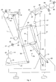
- a device according to the present invention to eliminate fluff from a yarn 11 is indicated in its entirety by the reference number 10 and is inserted into a singeing machine 12 comprising a generator device 13, suitable to generate a source of energy 14, which defines a processing zone 15, inside which the yarn 11 is made to transit and the process of eliminating the fluff is carried out.
- the source of energy 14 can be, for example, the flame generated by a gas burner. However, it comes within the spirit of the present invention to use alternative energy sources, for example sources generating an electric arc or others, suitable to obtain a burning process on a yarn in transit.
- the yarn 11 unwinds from a feed reel 16, is presence-controlled by a first sensor or feeler 18, the level of fluff is detected by a fluff detector 19, then it is tensed by the combined action of a yarn-guide roll 21 and a tensioner 22.
- the yarn 11 is disposed along a first axis of advance A1 by a first aligner guide 23, positioned in proximity to an entry zone 25 of the processing zone 15, and a second aligner guide 24 positioned in proximity to an exit zone 26 of the processing zone 15.
- the part of yarn 11 that is inside the processing zone 15 is subjected to a first pass of removing the fluff, or singeing, indicated in fig. 1 by a first arrow F1, directed from the entry zone 25 to the exit zone 26.
- the aligner guide 24 also has the function of diverting, in this case by about 90°, the path of the yarn 11.
- the yarn 11 is picked up again by a drawing and/or diversion roll 29, which in the case shown in fig. 1 is made to rotate by a motor 30, to be diverted thereby and directed along a return axis R1, outside the processing zone 15.
- the drawing and/or diversion roll 29 is not motorized and has only a diversion function.
- the aligner guide 23 and/or the aligner guide 24 are also motorized.
- the path of the yarn 11 is then again diverted by a third aligner guide 31, positioned in proximity to the entry zone 25 and cooperating with a fourth aligner guide 32, positioned downstream of the processing zone 15, to align the yarn 11 along a second axis of advance A2, in this case substantially parallel to the first axis of advance A1.
- a variant not shown in the drawings, provides that the yarn 11 is diverted by the first aligner guide 23, instead of the third aligner guide 31, and that the first aligner guide 23 cooperates with the fourth aligner guide 32.
- the part of the yarn 11 that is inside the processing zone 15 is subjected to a second pass of removing the fluff, or singeing, indicated in fig. 1 by a second arrow F2, directed from the entry zone 25 to the exit zone 26 and hence concordant with respect to the first arrow F1.
- the presence of the yarn 11 is again controlled by a second sensor or feeler 36, downstream of the processing zone 15, is made to transit, in this non-restrictive case, inside a traversing flue 37 and then picked up again by a winding roll 38, which is driven by a motor 39.
- a tension sensor 40 which controls the tension of the yarn 11 and possibly adjusts the drive of the winding roll 38, acting on its motor 39, to control the winding conditions of the yarn 11 onto a collection reel 43, driven by a corresponding motor 44.
- the drawing and/or diversion roll 29 and the aligner guides 23, 24, 31 and 32 can also be motorized or idle; this is to determine a guide, diversion and return system, outside the processing zone 15 which, as well as returning the yarn 11 to the processing zone 15, performing at least a second pass, concordant with respect to the first, of the yarn 11 in cooperation with the source of energy, also allows to adjust the tension of the yarn 11 which increases as the number of passes increases.
- the drawing and/or diversion roll 29 is motorized, its peripheral drawing speed of the yarn 11 will be greater than the peripheral speed of the winding roll 38 at least by 5%, advantageously at least by 10%, in order to discharge the increase in tension on the yarn 11 due to the diversions.
- aligner guides 23, 24, 31 or 32 are also motorized, their speeds will be greater than that of the winding roll 38 at least by 5%, advantageously at least by 10%. This is to discharge the increase in tension that has accumulated by the yarn 11 at every pass.
- Fig. 2 shows a second form of embodiment of the present invention.
- the same reference number is given to identical or equivalent components as those in fig. 1 ; furthermore, for clarity of representation, some components have been omitted.
- the yarn 11 is picked up again at exit from the processing zone 15 by the first drawing and/or diversion roll 124, which can be fixed, idle or motorized, which causes an inversion in the movement of the yarn 11 of about 180°.
- the second drawing and/or diversion roll 131 which can also be fixed, idle or motorized, causes a new inversion of the yarn 11 of about 180°, to return it inside the processing zone 15 so that a second pass can be carried out, having the same direction of advance as the first pass.
- peripheral speed of drawing the yarn 11 is preferably greater than the peripheral speed of the winding roll 38 by at least 5%, advantageously at least 10%.
- Fig. 3 shows a third form of embodiment of the present invention.
- the same reference number is given to the same or equivalent components as those in fig. 1 ; moreover, for clarity of representation, some components have been omitted.
- drawing and/or diversion rolls there are four drawing and/or diversion rolls, respectively 29, 231a and 231b and the aligner guide 24 also with function of drawing and/or diversion roll.
- the four drawing and/or diversion rolls 24, 29, 231a and 231b can be all fixed or idle, or motorized, or partly fixed, partly idle and partly motorized.
- the peripheral speed of the drawing and/or diversion rolls, 24, 29, 231a and 231b is preferably greater than the peripheral speed of the winding roll 38 by at least 5%, advantageously at least 10%.
- suction means 47 shown in fig. 1 , are associated both with the processing zone 15, and with the drawing and/or diversion roll 29 and with the traversing flue 37, to suck in and convey fumes, dust, particles and combustion products of the fluff inside a suction collector 48.
- Cleaning means for cleaning the yarn 11, which in this case comprise scrapers 49, are associated with the drawing and/or diversion roll 29 and the second aligner guide 24, and have the function of cleaning their surface, in the segment which at that moment is free of the passage of the yarn 11, by scraping the residues or dirt present on the surface of the latter.
- the cleaning means cooperate with the suction means 47, which discharge the residues and the dirt once they have been removed from the yarn 11.
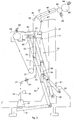
- a movement device 50 is connected to the singeing machine 12 and to the fluff eliminating device 10, and is suitable to move at least part of the latter during the heddling or relaunching steps of the yarn 11, which can occur for example at start-of-processing or following accidental breakages of the yarn 11.
- the movement device 50 comprises an actuator 51, in this case the pneumatic type, the cylinder 53 of which is attached externally to the singeing machine 12 and to a fixed upright 52, also attached to the singeing machine 12.
- the piston 54 of the actuator 51 is connected to a first girder 59, having one end hinged to the fixed upright 52 and the other end hinged on a mobile upright 58.
- a second girder 55 has one end hinged in correspondence to the top of the fixed upright 52, and one end hinged to the mobile upright 58, so as to define, with the first girder 59 and the two uprights 52, 58, a kinematism of the parallelogram type.
- a reel-carrier feed base 61 is made solid, on which the feed reel 16 is fixed, while at an upper end of the mobile upright 58 a support 62 is made solid, on which the drawing and/or diversion roll 29 and the second aligner guide 24 are mounted.
- the yarn-guide roll 21, the tensioner 22, the first aligner guide 23 and the third aligner guide 31 are also made solid with the mobile upright 58.
- the action of the actuator 51 selectively moves the mobile upright 58 closer to or away from the singeing machine 12, and consequently the elements made solid therewith.
- the piston 54 is at its maximum extension, so that the yarn 11 can be correctly positioned along its path while it is outside the processing zone 15 and the traversing flue 37.
- the piston 54 is totally retracted inside the cylinder 53 and the mobile upright 58 is positioned in proximity to the fixed upright 52.
- the yarn 11 is disposed and aligned as described previously and is able to be subjected to the singeing processes.
- a processing, control and command unit 64 which receives the information from the various members connected to it, such as the feelers 18, 36, the tensioner 22, the generator device 13, the fluff detector 19, the motor 30 of the drawing and/or diversion roll 29, which carries known torque indicator means, the tension sensor 40, the movement device 50, the motor 39 of the winding roll 38, the motor 44 of the collection reel 43, which carry speed and torque indicator means and any other possible motors that drive the various guides and/or drawing and/or diversion rolls.
- the various members connected to it such as the feelers 18, 36, the tensioner 22, the generator device 13, the fluff detector 19, the motor 30 of the drawing and/or diversion roll 29, which carries known torque indicator means, the tension sensor 40, the movement device 50, the motor 39 of the winding roll 38, the motor 44 of the collection reel 43, which carry speed and torque indicator means and any other possible motors that drive the various guides and/or drawing and/or diversion rolls.
- the processing unit 64 conditions the functioning of the device 10, adjusting the speed of the yarn 11 and/or the characteristics of the source of energy 14, acting for example on the generator device 13 and/or acting on the motors 30, 39, 44.
Landscapes
- Engineering & Computer Science (AREA)
- Textile Engineering (AREA)
- Yarns And Mechanical Finishing Of Yarns Or Ropes (AREA)
- Spinning Methods And Devices For Manufacturing Artificial Fibers (AREA)
Description
- The present invention concerns a device and the connected method suitable to eliminate the fluff present in yarns, especially those obtained mainly with short fibers, whether they are of vegetable, animal, artificial or synthetic origin.
- The so-called singeing method is known, by means of which a yarn which has an unacceptable degree of fluff, is made to transit inside a processing zone or a processing chamber, in proximity to a source of energy able to supply sufficient energy to burn the tips of the fibers protruding from the body of the yarn and which make up the fluff.
- Singeing carried out by known techniques is generally managed by adjusting only the speed of transit of the yarn in proximity to the source of energy, because this is the most easily controllable plant design parameter.
- The relation of inverse proportionality between fluff and the processing speed of the yarn, so that as the level of initial fluff increases there is a corresponding proportional reduction in the work speed, with obvious repercussions on the productivity of the plant, represents a limit and an important disadvantage of known singeing machines.
- It is therefore one purpose of the present invention to be able to obtain an adequate elimination of the fluff, at least equal to the results obtainable with known techniques, increasing the processing speed of the yarn and hence the productivity of the plant.
- In common practice, in the various known singeing solutions, there is also a high energy consumption, due to the fact that the energy is poorly used since the zone where the energy is generated is considerably oversized with respect to the dimensions of the fluff to be eliminated, and the energy is therefore greatly dispersed in the zone adjacent to the yarn.
- It is therefore another purpose of the present invention to obtain a reduction of the specific energy consumption, that is, the energy consumption per unit of mass of the yarn, of the singeing process.
- Another disadvantage of known singeing processes is connected to the degradation of the basic color of the body of the yarn, due to the fact that, to increase the reduction in fluff, the yarn is subjected for a longer time to the action of the flame. This is a serious disadvantage, because it requires remedies such as purging and bleaching, which are burdensome both in terms of working times, which is detrimental for productivity, and also in terms of cost, which is disadvantageous for the competitiveness of the product on the market.
- Another purpose of the present invention is therefore to actuate a method which is effective in eliminating the fluff from a yarn, and which allows to obtain good surface qualities of the yarn itself, without compromising the inner quality, so as to render the processing cheaper and quicker.
- The prior art document
US-A-6.151.764 describes a device and a method for singeing yarns, in particular for making carpets, in which the yarn is made to pass first in one direction then in the opposite direction in proximity to the flame of the singeing device. The prior art documentJP-A-6264323 GB-A-10.198 - These known solutions have the considerable disadvantage that the segments of yarn that translate simultaneously in a reciprocally inverse direction, and close to each other, generate a considerable reciprocal disturbance; this is because perturbations are created in the flame, and contrasting drawing effects on the flame and on the streams of air surrounding it, due to the opposite motion of adjacent segments of the yarn. This has a very negative influence on the singeing performance.
- Furthermore, the solutions where the yarn passes through the flame in a substantially transverse direction have a very poor performance, also because the drawing and accompanying effect, due to the motion of the yarn when it transits in proximity to the flame, is in no way exploited.
- The reduced performance of the singeing operation is even more accentuated as the passes in the singeing zone become more nmerous and the higher the transit speeds of the yarn are, and in current machines, and with the production requirements currently requested, these can reach as much as 1,200 meters per minute.
- It must be considered that, in gas singeing machines, the flame that develops in the processing zone, and which the yarn being worked passes through, has a length of about 100÷120 mm, and the yarn passes through the flame at a speed that can be comprised between 800 and 1,200 m/min; this means a passage time of about 6/1,000 of a second in which the fluff present on the surface of the yarn has to be burnt.
- As the transit speed increases, the disturbances, the turbulence and possible contacts between the yarns advancing in opposite directions are accentuated, determining a considerable drop in performance and efficiency of the process.
- Furthermore, if the two segments of yarn moving in opposite directions touch, the reciprocal speeds are added together, and the high-speed sliding causes new fluff that makes the singeing operation already performed inefficient.
- In those solutions known in the state of the art where two or more passes are provided, no control is contemplated of the tension of the yarn between one pass and the other, which tension increases with each pass after the first.
- An excessive tension in the subsequent passes, in particular for yarns with a fine or extra-fine count, can take the yarn to the limit point of its resistance, with consequent risks of fraying and breakage. On the contrary, if the tension is kept low to avoid these risks, at least for the first pass the yarn has too low a tension, and there may be instability, vibrations and slow oscillations of the yarn, and therefore poor performance of the process.
- The Applicant has devised, tested and embodied the present invention to overcome the shortcomings of the state of the art and to obtain these and other purposes and advantages.
- The present invention is set forth and characterized in the independent claims, while the dependent claims describe other characteristics of the present invention or variants to the main inventive idea.
- In accordance with the above purposes, a singeing method according to the present invention provides that a yarn, advancing at constant speed, or adjustable in a controlled manner, along a singeing machine, is made to transit through a suitable processing zone in which a source of high-intensity energy is positioned, to perform a first pass to remove the fluff.
- In a first non-restrictive solution, said source of high-intensity energy is at least a gas flame generator. In another solution, also non-restrictive, the source of high-intensity energy is at least an electric arc generator. Hereafter in the description, where the word flame is used, it must be understood that similar or equivalent considerations can apply, as and when possible, for electric arcs or other similar or equivalent energy forms.
- One characteristic of the present invention provides that the yarn, exiting from the processing zone, is picked up and diverted, outside the processing zone, to be returned toward the processing zone and to transit, substantially continuously, at least a second time inside the above-mentioned processing zone, in order to effect at least a second pass to remove the fluff, after the first pass. According to the present invention, the second pass occurs in a concordant direction, or same direction, as the first pass. A control and adjustment of the tension of the yarn is also provided at at least one point of the diversion, guide and return path between the first pass and the second pass.
- In other words, the yarn exiting from the singeing zone is made to transit in cooperation with at least two, advantageously three or more, drawing and/or controlled diversion means, suitable to perform a controlled adjustment of the tension applied to the yarn. Such drawing and/or controlled diversion means are configured to determine a diversion path on the yarn, which returns the yarn itself to follow, for at least a second time, for a second pass, the segment in the processing zone with the same direction of advance as in the first pass.
- In a preferred solution, during the second pass the segment of yarn is disposed substantially parallel, and in a position closely adjacent to the segment of yarn which is carrying out the first pass.
- If a third, fourth or larger number of passes of the yarn is provided in the processing zone, the invention provides that all these passes occur in the same direction of advance.
- In a preferred form of embodiment of the present invention, if the source of energy determines the formation of a flame in proximity to which the yarn is made to pass, the yarn in the processing zone moves in the same direction in which the flame develops.
- The fact that the directions of advance of the yarn in correspondence with the processing zone are equal, and even more the fact that the directions of advance with respect to the development of the flame are also equal, determines substantial advantages in terms of performance and efficiency of the process.
- In fact, the convective motions of the air created by the transit of the yarn, in two or more parallel and concordant segments, advantageously reciprocally close and also very near to the flame as well, determine a drawing effect on the flame itself; the flame thus accompanies the yarn for a certain segment beyond the specific generation zone, prolonging the effect deriving from the closeness between flame and fluff and hence increasing the efficiency of the singeing process. Furthermore, no reciprocal effects of turbulence and disturbance are created in the streams of air determined by crossings and passes in opposite directions.
- The multiple and concordant passes of the yarn in the processing zone therefore allow to increase the effect of burning the fluff, since the time the yarn remains in the processing zone is at least doubled, in close proximity and substantial temporal continuity, with the advantage of obtaining a better exploitation of the energy possessed by the above-mentioned source of energy and of obtaining a better level of singeing.
- This gives another advantage of using a singeing method with multiple and concordant passes, due to the possibility of carrying out all the passes of the yarn at greater working speeds than those currently used in the state of the art, which gives an increased productivity of the plant. The increased productivity is directly proportional to the ratio between the standard processing speeds used in the state of the art, and those used in a singeing machine which carries out the multiple pass, and for some types of yarn can even exceed 100%.
- Given the same level of fluff of the yarn at start and end of processing, and given the same overall consumption of energy by the plant, compared with the state of the art, the method using the multiple and concordant pass also has the advantage that it reduces the specific energy consumption, that is, the energy consumption per unit of mass of the yarn processed. This value is calculated as ratio between the overall energy consumption of a plant and its productivity.
- Another advantage of the present invention is that multiple and concordant passes at relatively high speeds have less impact on the quality of the body of the yarn, compared with a single pass at standard speed. The removal of the fluff made by a process with multiple passes is substantially equal to the sum of partial removals made by individual intermediate processes which, while being individually less effective compared with a pass made at a lower speed, also have lesser depth, and are therefore less harmful for the body of the yarn. The present invention is therefore advantageous in that it allows to have less recourse to purging and bleaching downstream of singeing.
- A further improvement of the process is obtained by using cleaning means, such as for example scrapers and brushes, which are positioned so as to act, sliding, on the surface of the drawing means, for example rolls or calenders, in a zone of the surface thereof where there is no yarn, in order to keep the surface of the roll or calender clean.
- The cleaning means cooperate with suction means, associated at least with the processing zone and with the drawing and alignment means, and having the function of aspirating and removing along at least part of the path of the yarn, the products of combustion, the fumes and the dust or particulate, which could dirty or ruin the yarn.
- The above-mentioned fact that the yarn passes several times inside the processing zone gives the advantage that it is exposed more to suction and recovery, and is hence cleaner at the end of the singeing process.
- According to a secondary characteristic of the present invention, at least a tension sensor cooperates with the drawing and/or controlled diversion means, and with winding means that can be motorized or idle, to control and adjust the speed of the yarn according to the tension detected by the tension sensor.
- As we said, a larger number of singeing passes entails a larger number of diversions of the yarn, which cause an increase in the tensions acting upon it, making it necessary to accurately control the tensions that progressively accumulate on the yarn, and to possibly intervene on the drawing and/or diversion means along the path of the yarn. Consequently, a greater control is advantageously obtained, by means of the drawing and/or diversion means, of the tensions to which the yarn is subjected along its path, hence safeguarding the correct collection conditions and preventing breakages and weakening of the yarn.
- It is within the spirit of the invention to provide that the drawing and/or diversion means and the winding means are synchronized with respect to each other.
- Another secondary characteristic of the present invention is to provide that the adjustment of the processing speed and/or the number of passes is correlated to the value of fluff of the yarn measured at entry to the processing zone, or the one measured at exit from the processing zone, or both, thus allowing the real-time management of the quality of the yarn, in every condition and for every requirement.
- The adjustments as above have the common purpose of optimizing the process of eliminating the fluff according to the present invention, and advantageously can lead to a considerable reduction in energy consumption if compared with the consumption of known processes.
- According to another secondary characteristic, the present invention provides that the yarn can be selectively distanced from and brought near to the processing zone. In this way it is possible to perform, outside the zone, in the distancing step, management operations of the singeing machine, such as heddling and the relaunching of the yarn, which can therefore be repositioned, in the subsequent approach or repositioning step, inside the processing zone.
- To this purpose, a movement device is provided, which connects the device for eliminating fluff to the singeing machine and comprises an actuator, suitable to move the fluff eliminating device with respect to the singeing machine, to selectively extract and insert the yarn in the processing zone.
- Other advantages due to the present invention are the possibility of inserting the yarn in the processing zone when a predetermined value of speed is reached, controlling the tensions inside the processing zone, to prevent stretching and breakage of the yarn, controlling the collection tension in order to facilitate the formation of reels for dye works.
- These and other characteristics of the present invention will become apparent from the following description of some preferential forms of embodiment, given as a non-restrictive example with reference to the attached drawings wherein:
-
fig. 1 shows schematically a first form of embodiment of a device according to the invention; -
figs. 2 and 3 show schematically two possible variants of the form of embodiment infig. 1 ; -
figs. 4 and5 show schematically a variant offig. 1 , in two different configurations. - In the following description, the same reference numbers indicate identical parts of the device for eliminating fluff according to the present invention, even in different forms of embodiment. It is understood that elements and characteristics of one form of embodiment can conveniently be incorporated into other forms of embodiment without further clarifications.
- With reference to
fig. 1 , a device according to the present invention to eliminate fluff from ayarn 11, is indicated in its entirety by thereference number 10 and is inserted into a singeingmachine 12 comprising agenerator device 13, suitable to generate a source ofenergy 14, which defines aprocessing zone 15, inside which theyarn 11 is made to transit and the process of eliminating the fluff is carried out. - The source of
energy 14 can be, for example, the flame generated by a gas burner. However, it comes within the spirit of the present invention to use alternative energy sources, for example sources generating an electric arc or others, suitable to obtain a burning process on a yarn in transit. - Hereafter we shall mainly describe a flame in the above non-restrictive meaning.
- In the form of embodiment shown in
fig. 1 , theyarn 11 unwinds from afeed reel 16, is presence-controlled by a first sensor orfeeler 18, the level of fluff is detected by afluff detector 19, then it is tensed by the combined action of a yarn-guide roll 21 and atensioner 22. - Then the
yarn 11 is disposed along a first axis of advance A1 by afirst aligner guide 23, positioned in proximity to anentry zone 25 of theprocessing zone 15, and asecond aligner guide 24 positioned in proximity to anexit zone 26 of theprocessing zone 15. - In the segment comprised between the first and
second aligner guide yarn 11 that is inside theprocessing zone 15 is subjected to a first pass of removing the fluff, or singeing, indicated infig. 1 by a first arrow F1, directed from theentry zone 25 to theexit zone 26. - The
aligner guide 24 also has the function of diverting, in this case by about 90°, the path of theyarn 11. - Then the
yarn 11 is picked up again by a drawing and/ordiversion roll 29, which in the case shown infig. 1 is made to rotate by amotor 30, to be diverted thereby and directed along a return axis R1, outside theprocessing zone 15. - According to a variant, not shown, the drawing and/or
diversion roll 29 is not motorized and has only a diversion function. According to other variants, not shown, thealigner guide 23 and/or thealigner guide 24 are also motorized. - The path of the
yarn 11 is then again diverted by athird aligner guide 31, positioned in proximity to theentry zone 25 and cooperating with afourth aligner guide 32, positioned downstream of theprocessing zone 15, to align theyarn 11 along a second axis of advance A2, in this case substantially parallel to the first axis of advance A1. - A variant, not shown in the drawings, provides that the
yarn 11 is diverted by thefirst aligner guide 23, instead of thethird aligner guide 31, and that thefirst aligner guide 23 cooperates with thefourth aligner guide 32. - In the segment comprised between the third and fourth aligner guides 31, 32, the part of the
yarn 11 that is inside theprocessing zone 15 is subjected to a second pass of removing the fluff, or singeing, indicated infig. 1 by a second arrow F2, directed from theentry zone 25 to theexit zone 26 and hence concordant with respect to the first arrow F1. - Afterward, the presence of the
yarn 11 is again controlled by a second sensor orfeeler 36, downstream of theprocessing zone 15, is made to transit, in this non-restrictive case, inside a traversingflue 37 and then picked up again by a windingroll 38, which is driven by amotor 39. - In the non-restrictive form of embodiment shown, in proximity to the traversing
flue 37 there is atension sensor 40, which controls the tension of theyarn 11 and possibly adjusts the drive of the windingroll 38, acting on itsmotor 39, to control the winding conditions of theyarn 11 onto acollection reel 43, driven by a correspondingmotor 44. - As we said, as well as the winding
roll 38, which is motorized, the drawing and/ordiversion roll 29 and the aligner guides 23, 24, 31 and 32 can also be motorized or idle; this is to determine a guide, diversion and return system, outside theprocessing zone 15 which, as well as returning theyarn 11 to theprocessing zone 15, performing at least a second pass, concordant with respect to the first, of theyarn 11 in cooperation with the source of energy, also allows to adjust the tension of theyarn 11 which increases as the number of passes increases. - For example, if the drawing and/or
diversion roll 29 is motorized, its peripheral drawing speed of theyarn 11 will be greater than the peripheral speed of the windingroll 38 at least by 5%, advantageously at least by 10%, in order to discharge the increase in tension on theyarn 11 due to the diversions. - If one or more of the aligner guides 23, 24, 31 or 32 are also motorized, their speeds will be greater than that of the winding
roll 38 at least by 5%, advantageously at least by 10%. This is to discharge the increase in tension that has accumulated by theyarn 11 at every pass. -
Fig. 2 shows a second form of embodiment of the present invention. In this drawing, the same reference number is given to identical or equivalent components as those infig. 1 ; furthermore, for clarity of representation, some components have been omitted. - In the solution shown in
fig. 2 , there are two drawing and/or diversion rolls 124 and 131 which, in practice, perform the function of the aligner guides 24 and 31 and of the drawing and/ordiversion roll 29 of the solution infig. 1 . - In this case the
yarn 11 is picked up again at exit from theprocessing zone 15 by the first drawing and/ordiversion roll 124, which can be fixed, idle or motorized, which causes an inversion in the movement of theyarn 11 of about 180°. The second drawing and/ordiversion roll 131, which can also be fixed, idle or motorized, causes a new inversion of theyarn 11 of about 180°, to return it inside theprocessing zone 15 so that a second pass can be carried out, having the same direction of advance as the first pass. - In this case too, if one or both the drawing and/or diversion rolls 124 and 131 are motorized, their peripheral speed of drawing the
yarn 11 is preferably greater than the peripheral speed of the windingroll 38 by at least 5%, advantageously at least 10%. -
Fig. 3 shows a third form of embodiment of the present invention. In this figure, the same reference number is given to the same or equivalent components as those infig. 1 ; moreover, for clarity of representation, some components have been omitted. - In the solution in
fig. 3 , there are four drawing and/or diversion rolls, respectively 29, 231a and 231b and thealigner guide 24 also with function of drawing and/or diversion roll. As in the previous cases, the four drawing and/or diversion rolls 24, 29, 231a and 231b can be all fixed or idle, or motorized, or partly fixed, partly idle and partly motorized. - If they are motorized, the peripheral speed of the drawing and/or diversion rolls, 24, 29, 231a and 231b is preferably greater than the peripheral speed of the winding
roll 38 by at least 5%, advantageously at least 10%. - It comes within the spirit of the invention to provide, for each form of embodiment described above, that suction means 47, shown in
fig. 1 , are associated both with theprocessing zone 15, and with the drawing and/ordiversion roll 29 and with the traversingflue 37, to suck in and convey fumes, dust, particles and combustion products of the fluff inside asuction collector 48. - Cleaning means for cleaning the
yarn 11, which in this case comprisescrapers 49, are associated with the drawing and/ordiversion roll 29 and thesecond aligner guide 24, and have the function of cleaning their surface, in the segment which at that moment is free of the passage of theyarn 11, by scraping the residues or dirt present on the surface of the latter. - The cleaning means cooperate with the suction means 47, which discharge the residues and the dirt once they have been removed from the
yarn 11. - According to a variant of the present invention (
figs. 4 and5 ), amovement device 50 is connected to the singeingmachine 12 and to thefluff eliminating device 10, and is suitable to move at least part of the latter during the heddling or relaunching steps of theyarn 11, which can occur for example at start-of-processing or following accidental breakages of theyarn 11. Themovement device 50 comprises anactuator 51, in this case the pneumatic type, thecylinder 53 of which is attached externally to the singeingmachine 12 and to a fixedupright 52, also attached to the singeingmachine 12. Thepiston 54 of theactuator 51 is connected to afirst girder 59, having one end hinged to the fixedupright 52 and the other end hinged on amobile upright 58. Asecond girder 55 has one end hinged in correspondence to the top of the fixedupright 52, and one end hinged to themobile upright 58, so as to define, with thefirst girder 59 and the twouprights carrier feed base 61 is made solid, on which thefeed reel 16 is fixed, while at an upper end of the mobile upright 58 asupport 62 is made solid, on which the drawing and/ordiversion roll 29 and thesecond aligner guide 24 are mounted. The yarn-guide roll 21, thetensioner 22, thefirst aligner guide 23 and thethird aligner guide 31 are also made solid with themobile upright 58. - The action of the
actuator 51 selectively moves themobile upright 58 closer to or away from the singeingmachine 12, and consequently the elements made solid therewith. In the heddling step (fig. 4 ), thepiston 54 is at its maximum extension, so that theyarn 11 can be correctly positioned along its path while it is outside theprocessing zone 15 and the traversingflue 37. - In the working position (
fig. 5 ), thepiston 54 is totally retracted inside thecylinder 53 and themobile upright 58 is positioned in proximity to the fixedupright 52. In this position, theyarn 11 is disposed and aligned as described previously and is able to be subjected to the singeing processes. - For every form of embodiment of the present invention, but shown here by way of example only in
fig. 1 , a processing, control andcommand unit 64 is provided, which receives the information from the various members connected to it, such as thefeelers tensioner 22, thegenerator device 13, thefluff detector 19, themotor 30 of the drawing and/ordiversion roll 29, which carries known torque indicator means, thetension sensor 40, themovement device 50, themotor 39 of the windingroll 38, themotor 44 of thecollection reel 43, which carry speed and torque indicator means and any other possible motors that drive the various guides and/or drawing and/or diversion rolls. - Based on the information collected and on the possible programs connected to the type of
yarn 11 and the desired fluff at exit, theprocessing unit 64 conditions the functioning of thedevice 10, adjusting the speed of theyarn 11 and/or the characteristics of the source ofenergy 14, acting for example on thegenerator device 13 and/or acting on themotors - It should be noted here that with the invention it is possible both to adjust a single yarn completely, providing independent
fluff elimination devices 10, and also to driveseveral devices 10, by common members which drive both the windingroll 38 and also thecorresponding collection reels 43. - It also comes within the spirit of the invention to adjust the
device 10 and/or themovement device 50 either manually or semi-automatically.
Claims (17)
- Method to eliminate fluff from a yarn (11), comprising a first step in which said yarn (11) is made to transit in a processing zone (15) of a singeing machine (12) in which a source of high intensity energy (14) is positioned in order to carry out a first pass (F1) of removing the fluff, and at least a second step in which said yarn (11), exiting from said processing zone (15), is picked up again and diverted in order to be made to transit substantially continuously at least a second time inside said processing zone (15), in proximity to said source of energy (14), in order to carry out at least a second pass (F2) of removing the fluff, characterized in that said second pass (F2) occurs in a direction concordant with the first pass (F1), a control and adjustment also being provided of the tension of the yarn (11) in at least one point of the diversion, guide and return path, between the first pass (F1) and the second pass (F2).
- Method as in claim 1, characterized in that in the case where said source of energy (14) determines the formation of a flame in proximity to which the yarn (11) is made to transit, the yarn (11) in the processing zone (15) moves in the same direction in which the flame develops.
- Method as in claim 1 or 2, characterized in that after the at least one second pass (F2) in the processing zone (15) it provides a step of winding the yarn (11), carried out by a motorized winding roll (38).
- Method as in any claim hereinbefore, characterized in that between the first pass (F1) and the second pass (F2) a step of diversion, guide and return of the yarn (11) is provided, carried out by at least two guides and/or diversion rolls (29, 23, 24, 31 and 32; 124, 131; 231a, 231b).
- Method as in claims 3 and 4, wherein it provides that at least one of said guides and/or diversion rolls (29, 23, 24, 31 and 32; 124, 131; 231a, 231b) is motorized and driven at an adjustable peripheral speed and in any case higher than that of said winding roll (38).
- Method as in claim 5, characterized in that the peripheral drawing speed of the yarn (11) of the motorized guides and/or diversion roll or rolls (29, 23, 24, 31 and 32; 124, 131; 231a, 231b) is at least 5% higher, advantageously at least 10%, than the peripheral speed of the winding roll (38).
- Method as in any claim hereinbefore, characterized in that the number of passes to remove the fluff of said yarn (11) inside said processing zone (15) is adjustable according to the type of said yarn (11) and/or its fluff.
- Method as in any claim hereinbefore, characterized in that it provides that the tension of said yarn (11) is constantly controlled along the path of said yarn (11) in said singeing machine (12), and that a control unit (64) acts on the motors at least of said winding roll (38) and/or one or more of said guides and/or diversion rolls (29, 23, 24, 31 and 32; 124, 131; 231a, 231b) to maintain or return the tension of the yarn (11) at/to a desired value.
- Method as in any claim hereinbefore, characterized in that it provides to suck in and remove the fumes, dust and combustion products along at least part of the path of said yarn (11).
- Method as in any claim hereinbefore, characterized in that it also comprises a step of distancing the yarn (11) from said processing zone (15), in order to effect, outside the latter, operations to manage said singeing machine (12), such as heddling and re-launching the yarn (11), and an approach or repositioning step, after said distancing step, in which said yarn (11) is repositioned inside said processing zone (15).
- Device to eliminate fluff from a yarn (11), comprising a singeing machine (12) defining at least a processing zone (15), in which a source of high intensity energy (14) is positioned, and guides and/or diversion rolls (29, 23, 24, 31 and 32; 124, 131; 231a, 231b) positioned on opposite sides with respect to said processing zone (15) and able to define a first segment of the path of said yarn (11) inside said processing zone (15), to carry out a first pass (F1) of removing the fluff, characterized in that said guides and/or diversion rolls (29, 23, 24, 31 and 32; 124, 131; 231a, 231b) are configured to define a guide, diversion and return path, to bring said yarn (11), exiting from the first pass (F1) in the processing zone (15), to complete at least a second pass (F2) in the processing zone (15) in the same direction as the first pass (F1), said second pass (F2) being in the same direction as said first pass (F1), the device also comprising means to control and adjust the tension of the yarn (11) disposed in at least one point of the diversion, guide and return path, between the first pass (F1) and the second pass (F2).
- Device as in claim 11, characterized in that said means to control and adjust the tension of the yarn (11) comprise a motorized winding roll (38) disposed downstream of the singeing machine (12) and from which the yarn (11) exiting from the at least one second pass (F2) is drawn, and at least a guide and/or diversion roll (29, 23, 24, 31 and 32; 124, 131; 231a, 231b) disposed downstream of the singeing machine (12) and on which the yarn (11) exiting from the first pass (F1) winds.
- Device as in claim 12, characterized in that at least one of said guides and/or diversion rolls (29, 23, 24, 31 and 32; 124, 131; 231a, 231b) is motorized.
- Device as in claim 12 or 13, characterized in that said means to control and adjust the tension of the yarn (11) also comprise at least a tension sensor (40) disposed along the path of the yarn (11) and a control unit (64), wherein said control unit (64) is configured to receive at least the value of the tension of the yarn (11) from said at least one tension sensor (40) and to act on the drive of said winding roll (38) and/or of at least one of said guides and/or diversion rolls (29, 23, 24, 31 and 32; 124, 131; 231a, 231b) in order to maintain or return the tension at/to to a desired value.
- Device as in claim 14, characterized in that said control unit is configured to maintain the peripheral yarn drawing speed of the at least one motorized guide and/or diversion roll (29, 23, 24, 31 and 32; 124, 131; 231a, 231b) at a value higher than at least 5%, advantageously at least 10%, with respect to the peripheral speed of the winding roll (38).
- Device as in any claim from 10 to 14, characterized in that a movement device (50) connects said device (10) to said singeing machine (12) and comprises an actuator (51), suitable to move said device (10) with respect to said singeing machine (12), in order to selectively extract and insert said yarn (11) from/into said processing zone (15).
- Device as in any claim from 12 to 16, characterized in that it comprises cleaning means (49) associated at least to one of said guide and/or diversion rolls (29, 23, 24, 31 and 32; 124, 131; 231a, 231b).
Applications Claiming Priority (2)
| Application Number | Priority Date | Filing Date | Title |
|---|---|---|---|
| IT000047A ITUD20120047A1 (en) | 2012-03-21 | 2012-03-21 | DEVICE AND PROCEDURE FOR THE ELIMINATION OF THE PELOSITY OF A YARN |
| PCT/EP2013/055817 WO2013139855A1 (en) | 2012-03-21 | 2013-03-20 | Device and method to eliminate fluff from a yarn |
Publications (2)
| Publication Number | Publication Date |
|---|---|
| EP2828424A1 EP2828424A1 (en) | 2015-01-28 |
| EP2828424B1 true EP2828424B1 (en) | 2016-03-16 |
Family
ID=46022591
Family Applications (1)
| Application Number | Title | Priority Date | Filing Date |
|---|---|---|---|
| EP13713394.8A Not-in-force EP2828424B1 (en) | 2012-03-21 | 2013-03-20 | Device and method to eliminate fluff from a yarn |
Country Status (4)
| Country | Link |
|---|---|
| EP (1) | EP2828424B1 (en) |
| CN (1) | CN104379824A (en) |
| IT (1) | ITUD20120047A1 (en) |
| WO (1) | WO2013139855A1 (en) |
Families Citing this family (6)
| Publication number | Priority date | Publication date | Assignee | Title |
|---|---|---|---|---|
| CN103510234B (en) * | 2013-09-27 | 2015-11-18 | 山东同济机电有限公司 | For the overfeeding formula yarn path of spun silk singeing |
| CN105274695B (en) * | 2015-10-26 | 2017-08-04 | 武汉纺织大学 | A kind of clean beaming method of ultraphotic of many fibrous yarn lines |
| CN105624926B (en) * | 2016-01-06 | 2017-09-15 | 灵氟隆新材料科技江苏有限公司 | The method of fiber filoplume is split for reducing poly tetrafluoroethylene |
| CN107217434B (en) * | 2017-07-21 | 2019-05-21 | 江苏明晶布业股份有限公司 | One kind singes, calendering device |
| IT201900002353A1 (en) * | 2019-02-18 | 2020-08-18 | Ricambi Tessili Ri Te S R L | APPARATUS FOR REMOVING THE HAIR OF A YARN AND RELATIVE PROCEDURE |
| CN110396794B (en) * | 2019-08-09 | 2020-06-05 | 南京六六创业科技有限公司 | Device is repaired to plant fiber product surface palpus silk |
Family Cites Families (9)
| Publication number | Priority date | Publication date | Assignee | Title |
|---|---|---|---|---|
| GB189610198A (en) * | 1896-05-13 | 1896-10-17 | Geo Swindells & Son Ltd | Improvements in Gassing Frames for Gassing Yarn, Thread, and the like. |
| GB309320A (en) * | 1928-04-23 | 1929-04-11 | Osthoff Fa Walter | Improvements in processes for singeing textile goods and apparatus therefor |
| US3421746A (en) * | 1967-04-24 | 1969-01-14 | Lyle E Mccoy | Heating apparatus for elongate material |
| CN2138659Y (en) * | 1992-08-26 | 1993-07-21 | 上海第四纺织机械厂 | Spun silk singeing device |
| JPH06264323A (en) * | 1993-03-09 | 1994-09-20 | Kanebo Ltd | Device for protecting fire in yarn fluff burning machine |
| US6151764A (en) * | 1998-12-24 | 2000-11-28 | Osthoff-Senge Gmbh & Co. Kg | Apparatus for the singeing of threads |
| CN201381408Y (en) * | 2009-03-17 | 2010-01-13 | 鲁丰织染有限公司 | Hair-feather burning device for slashing |
| CN201420177Y (en) * | 2009-04-27 | 2010-03-10 | 江苏三房巷实业股份有限公司 | Dyeing-finishing-process singeing device |
| CN101880945A (en) * | 2010-06-25 | 2010-11-10 | 巨石攀登电子基材有限公司 | Glass fiber cloth singeing technology and production mechanism using same |
-
2012
- 2012-03-21 IT IT000047A patent/ITUD20120047A1/en unknown
-
2013
- 2013-03-20 WO PCT/EP2013/055817 patent/WO2013139855A1/en not_active Ceased
- 2013-03-20 EP EP13713394.8A patent/EP2828424B1/en not_active Not-in-force
- 2013-03-20 CN CN201380026224.3A patent/CN104379824A/en active Pending
Also Published As
| Publication number | Publication date |
|---|---|
| EP2828424A1 (en) | 2015-01-28 |
| ITUD20120047A1 (en) | 2013-09-22 |
| CN104379824A (en) | 2015-02-25 |
| WO2013139855A1 (en) | 2013-09-26 |
Similar Documents
| Publication | Publication Date | Title |
|---|---|---|
| EP2828424A1 (en) | Device and method to eliminate fluff from a yarn | |
| CN106567170B (en) | Textile machine and control device | |
| CN105177774A (en) | Semi-automatic opening rotor spinning machine | |
| TW200728528A (en) | Apparatus for melt spinning and windup of synthetic yarn | |
| CN205474168U (en) | Cleaning device , drafting arrangement and spinning machine | |
| CN108130639B (en) | Textile machine and textile method | |
| EP2949793B1 (en) | Spinning machine and spinning method | |
| EP1959042A4 (en) | METHOD AND DEVICE FOR SPEEDING A THREAD | |
| JP5944838B2 (en) | Draft device with guide table for guide apron | |
| CN110029412B (en) | Spinning machine and spinning method | |
| CN209368429U (en) | A kind of warping machine of Quick-threading | |
| EP2752513B1 (en) | Spinning machine | |
| JP2017071870A (en) | Draft device, spinning machine, and spinning method | |
| CN116791248A (en) | Automatic splicing device and method for fabric ring spinning machine | |
| CN210506700U (en) | Fabric processing device | |
| JP2021038476A (en) | Management device of spinning machine and spinning machine equipped with management device | |
| CN206467391U (en) | A kind of feeding device of sectional warper | |
| CN220767299U (en) | Yarn singeing device | |
| EP2949794B1 (en) | Spinning machine and spinning method | |
| EP3168340B1 (en) | Air spinning device and spinning machine | |
| KR20210123169A (en) | Tape-type weft width equalization supply device and spreading tow fabric weaving system including the supply device | |
| JP2015081398A (en) | Draft device and spinning machine | |
| IT9022544A1 (en) | PROCEDURE FOR THE PRODUCTION OF A MULTI-COMPONENT ELASTIC THREAD IN A SPINNING MACHINE AND DEVICE FOR THE IMPLEMENTATION OF THE PROCEDURE. | |
| CN215440824U (en) | Female yarn warper for loom | |
| ITMI20061653A1 (en) | KNITTING MANUFACTURER |
Legal Events
| Date | Code | Title | Description |
|---|---|---|---|
| PUAI | Public reference made under article 153(3) epc to a published international application that has entered the european phase |
Free format text: ORIGINAL CODE: 0009012 |
|
| 17P | Request for examination filed |
Effective date: 20141021 |
|
| AK | Designated contracting states |
Kind code of ref document: A1 Designated state(s): AL AT BE BG CH CY CZ DE DK EE ES FI FR GB GR HR HU IE IS IT LI LT LU LV MC MK MT NL NO PL PT RO RS SE SI SK SM TR |
|
| AX | Request for extension of the european patent |
Extension state: BA ME |
|
| DAX | Request for extension of the european patent (deleted) | ||
| GRAP | Despatch of communication of intention to grant a patent |
Free format text: ORIGINAL CODE: EPIDOSNIGR1 |
|
| INTG | Intention to grant announced |
Effective date: 20150915 |
|
| GRAS | Grant fee paid |
Free format text: ORIGINAL CODE: EPIDOSNIGR3 |
|
| GRAA | (expected) grant |
Free format text: ORIGINAL CODE: 0009210 |
|
| AK | Designated contracting states |
Kind code of ref document: B1 Designated state(s): AL AT BE BG CH CY CZ DE DK EE ES FI FR GB GR HR HU IE IS IT LI LT LU LV MC MK MT NL NO PL PT RO RS SE SI SK SM TR |
|
| REG | Reference to a national code |
Ref country code: GB Ref legal event code: FG4D |
|
| REG | Reference to a national code |
Ref country code: CH Ref legal event code: EP |
|
| REG | Reference to a national code |
Ref country code: IE Ref legal event code: FG4D |
|
| REG | Reference to a national code |
Ref country code: AT Ref legal event code: REF Ref document number: 781346 Country of ref document: AT Kind code of ref document: T Effective date: 20160415 |
|
| REG | Reference to a national code |
Ref country code: DE Ref legal event code: R096 Ref document number: 602013005543 Country of ref document: DE |
|
| REG | Reference to a national code |
Ref country code: NL Ref legal event code: MP Effective date: 20160316 |
|
| REG | Reference to a national code |
Ref country code: LT Ref legal event code: MG4D |
|
| PG25 | Lapsed in a contracting state [announced via postgrant information from national office to epo] |
Ref country code: NO Free format text: LAPSE BECAUSE OF FAILURE TO SUBMIT A TRANSLATION OF THE DESCRIPTION OR TO PAY THE FEE WITHIN THE PRESCRIBED TIME-LIMIT Effective date: 20160616 Ref country code: HR Free format text: LAPSE BECAUSE OF FAILURE TO SUBMIT A TRANSLATION OF THE DESCRIPTION OR TO PAY THE FEE WITHIN THE PRESCRIBED TIME-LIMIT Effective date: 20160316 Ref country code: GR Free format text: LAPSE BECAUSE OF FAILURE TO SUBMIT A TRANSLATION OF THE DESCRIPTION OR TO PAY THE FEE WITHIN THE PRESCRIBED TIME-LIMIT Effective date: 20160617 Ref country code: FI Free format text: LAPSE BECAUSE OF FAILURE TO SUBMIT A TRANSLATION OF THE DESCRIPTION OR TO PAY THE FEE WITHIN THE PRESCRIBED TIME-LIMIT Effective date: 20160316 |
|
| REG | Reference to a national code |
Ref country code: AT Ref legal event code: MK05 Ref document number: 781346 Country of ref document: AT Kind code of ref document: T Effective date: 20160316 |
|
| PG25 | Lapsed in a contracting state [announced via postgrant information from national office to epo] |
Ref country code: BE Free format text: LAPSE BECAUSE OF NON-PAYMENT OF DUE FEES Effective date: 20160331 Ref country code: NL Free format text: LAPSE BECAUSE OF FAILURE TO SUBMIT A TRANSLATION OF THE DESCRIPTION OR TO PAY THE FEE WITHIN THE PRESCRIBED TIME-LIMIT Effective date: 20160316 Ref country code: LV Free format text: LAPSE BECAUSE OF FAILURE TO SUBMIT A TRANSLATION OF THE DESCRIPTION OR TO PAY THE FEE WITHIN THE PRESCRIBED TIME-LIMIT Effective date: 20160316 Ref country code: LT Free format text: LAPSE BECAUSE OF FAILURE TO SUBMIT A TRANSLATION OF THE DESCRIPTION OR TO PAY THE FEE WITHIN THE PRESCRIBED TIME-LIMIT Effective date: 20160316 Ref country code: SE Free format text: LAPSE BECAUSE OF FAILURE TO SUBMIT A TRANSLATION OF THE DESCRIPTION OR TO PAY THE FEE WITHIN THE PRESCRIBED TIME-LIMIT Effective date: 20160316 Ref country code: RS Free format text: LAPSE BECAUSE OF FAILURE TO SUBMIT A TRANSLATION OF THE DESCRIPTION OR TO PAY THE FEE WITHIN THE PRESCRIBED TIME-LIMIT Effective date: 20160316 |
|
| REG | Reference to a national code |
Ref country code: DE Ref legal event code: R119 Ref document number: 602013005543 Country of ref document: DE |
|
| PG25 | Lapsed in a contracting state [announced via postgrant information from national office to epo] |
Ref country code: PL Free format text: LAPSE BECAUSE OF FAILURE TO SUBMIT A TRANSLATION OF THE DESCRIPTION OR TO PAY THE FEE WITHIN THE PRESCRIBED TIME-LIMIT Effective date: 20160316 Ref country code: EE Free format text: LAPSE BECAUSE OF FAILURE TO SUBMIT A TRANSLATION OF THE DESCRIPTION OR TO PAY THE FEE WITHIN THE PRESCRIBED TIME-LIMIT Effective date: 20160316 Ref country code: IS Free format text: LAPSE BECAUSE OF FAILURE TO SUBMIT A TRANSLATION OF THE DESCRIPTION OR TO PAY THE FEE WITHIN THE PRESCRIBED TIME-LIMIT Effective date: 20160716 |
|
| REG | Reference to a national code |
Ref country code: CH Ref legal event code: PL |
|
| PG25 | Lapsed in a contracting state [announced via postgrant information from national office to epo] |
Ref country code: SM Free format text: LAPSE BECAUSE OF FAILURE TO SUBMIT A TRANSLATION OF THE DESCRIPTION OR TO PAY THE FEE WITHIN THE PRESCRIBED TIME-LIMIT Effective date: 20160316 Ref country code: AT Free format text: LAPSE BECAUSE OF FAILURE TO SUBMIT A TRANSLATION OF THE DESCRIPTION OR TO PAY THE FEE WITHIN THE PRESCRIBED TIME-LIMIT Effective date: 20160316 Ref country code: PT Free format text: LAPSE BECAUSE OF FAILURE TO SUBMIT A TRANSLATION OF THE DESCRIPTION OR TO PAY THE FEE WITHIN THE PRESCRIBED TIME-LIMIT Effective date: 20160718 Ref country code: CZ Free format text: LAPSE BECAUSE OF FAILURE TO SUBMIT A TRANSLATION OF THE DESCRIPTION OR TO PAY THE FEE WITHIN THE PRESCRIBED TIME-LIMIT Effective date: 20160316 Ref country code: SK Free format text: LAPSE BECAUSE OF FAILURE TO SUBMIT A TRANSLATION OF THE DESCRIPTION OR TO PAY THE FEE WITHIN THE PRESCRIBED TIME-LIMIT Effective date: 20160316 Ref country code: RO Free format text: LAPSE BECAUSE OF FAILURE TO SUBMIT A TRANSLATION OF THE DESCRIPTION OR TO PAY THE FEE WITHIN THE PRESCRIBED TIME-LIMIT Effective date: 20160316 Ref country code: ES Free format text: LAPSE BECAUSE OF FAILURE TO SUBMIT A TRANSLATION OF THE DESCRIPTION OR TO PAY THE FEE WITHIN THE PRESCRIBED TIME-LIMIT Effective date: 20160316 |
|
| REG | Reference to a national code |
Ref country code: IE Ref legal event code: MM4A |
|
| PG25 | Lapsed in a contracting state [announced via postgrant information from national office to epo] |
Ref country code: IT Free format text: LAPSE BECAUSE OF FAILURE TO SUBMIT A TRANSLATION OF THE DESCRIPTION OR TO PAY THE FEE WITHIN THE PRESCRIBED TIME-LIMIT Effective date: 20160316 Ref country code: BE Free format text: LAPSE BECAUSE OF FAILURE TO SUBMIT A TRANSLATION OF THE DESCRIPTION OR TO PAY THE FEE WITHIN THE PRESCRIBED TIME-LIMIT Effective date: 20160316 |
|
| PLBE | No opposition filed within time limit |
Free format text: ORIGINAL CODE: 0009261 |
|
| STAA | Information on the status of an ep patent application or granted ep patent |
Free format text: STATUS: NO OPPOSITION FILED WITHIN TIME LIMIT |
|
| PG25 | Lapsed in a contracting state [announced via postgrant information from national office to epo] |
Ref country code: DE Free format text: LAPSE BECAUSE OF NON-PAYMENT OF DUE FEES Effective date: 20161001 Ref country code: CH Free format text: LAPSE BECAUSE OF NON-PAYMENT OF DUE FEES Effective date: 20160331 Ref country code: IE Free format text: LAPSE BECAUSE OF NON-PAYMENT OF DUE FEES Effective date: 20160320 Ref country code: LI Free format text: LAPSE BECAUSE OF NON-PAYMENT OF DUE FEES Effective date: 20160331 Ref country code: DK Free format text: LAPSE BECAUSE OF FAILURE TO SUBMIT A TRANSLATION OF THE DESCRIPTION OR TO PAY THE FEE WITHIN THE PRESCRIBED TIME-LIMIT Effective date: 20160316 |
|
| REG | Reference to a national code |
Ref country code: FR Ref legal event code: ST Effective date: 20170116 |
|
| 26N | No opposition filed |
Effective date: 20161219 |
|
| PG25 | Lapsed in a contracting state [announced via postgrant information from national office to epo] |
Ref country code: BG Free format text: LAPSE BECAUSE OF FAILURE TO SUBMIT A TRANSLATION OF THE DESCRIPTION OR TO PAY THE FEE WITHIN THE PRESCRIBED TIME-LIMIT Effective date: 20160616 |
|
| PG25 | Lapsed in a contracting state [announced via postgrant information from national office to epo] |
Ref country code: FR Free format text: LAPSE BECAUSE OF NON-PAYMENT OF DUE FEES Effective date: 20160517 |
|
| PG25 | Lapsed in a contracting state [announced via postgrant information from national office to epo] |
Ref country code: SI Free format text: LAPSE BECAUSE OF FAILURE TO SUBMIT A TRANSLATION OF THE DESCRIPTION OR TO PAY THE FEE WITHIN THE PRESCRIBED TIME-LIMIT Effective date: 20160316 |
|
| PG25 | Lapsed in a contracting state [announced via postgrant information from national office to epo] |
Ref country code: MT Free format text: LAPSE BECAUSE OF FAILURE TO SUBMIT A TRANSLATION OF THE DESCRIPTION OR TO PAY THE FEE WITHIN THE PRESCRIBED TIME-LIMIT Effective date: 20160316 |
|
| GBPC | Gb: european patent ceased through non-payment of renewal fee |
Effective date: 20170320 |
|
| PG25 | Lapsed in a contracting state [announced via postgrant information from national office to epo] |
Ref country code: GB Free format text: LAPSE BECAUSE OF NON-PAYMENT OF DUE FEES Effective date: 20170320 |
|
| PG25 | Lapsed in a contracting state [announced via postgrant information from national office to epo] |
Ref country code: HU Free format text: LAPSE BECAUSE OF FAILURE TO SUBMIT A TRANSLATION OF THE DESCRIPTION OR TO PAY THE FEE WITHIN THE PRESCRIBED TIME-LIMIT; INVALID AB INITIO Effective date: 20130320 |
|
| PG25 | Lapsed in a contracting state [announced via postgrant information from national office to epo] |
Ref country code: CY Free format text: LAPSE BECAUSE OF FAILURE TO SUBMIT A TRANSLATION OF THE DESCRIPTION OR TO PAY THE FEE WITHIN THE PRESCRIBED TIME-LIMIT Effective date: 20160316 Ref country code: MC Free format text: LAPSE BECAUSE OF FAILURE TO SUBMIT A TRANSLATION OF THE DESCRIPTION OR TO PAY THE FEE WITHIN THE PRESCRIBED TIME-LIMIT Effective date: 20160316 Ref country code: MT Free format text: LAPSE BECAUSE OF FAILURE TO SUBMIT A TRANSLATION OF THE DESCRIPTION OR TO PAY THE FEE WITHIN THE PRESCRIBED TIME-LIMIT Effective date: 20160331 Ref country code: MK Free format text: LAPSE BECAUSE OF FAILURE TO SUBMIT A TRANSLATION OF THE DESCRIPTION OR TO PAY THE FEE WITHIN THE PRESCRIBED TIME-LIMIT Effective date: 20160316 Ref country code: LU Free format text: LAPSE BECAUSE OF NON-PAYMENT OF DUE FEES Effective date: 20160320 |
|
| PG25 | Lapsed in a contracting state [announced via postgrant information from national office to epo] |
Ref country code: AL Free format text: LAPSE BECAUSE OF FAILURE TO SUBMIT A TRANSLATION OF THE DESCRIPTION OR TO PAY THE FEE WITHIN THE PRESCRIBED TIME-LIMIT Effective date: 20160316 Ref country code: TR Free format text: LAPSE BECAUSE OF FAILURE TO SUBMIT A TRANSLATION OF THE DESCRIPTION OR TO PAY THE FEE WITHIN THE PRESCRIBED TIME-LIMIT Effective date: 20160316 |