EP2827823B1 - Resilient side rails for medical tables - Google Patents
Resilient side rails for medical tables Download PDFInfo
- Publication number
- EP2827823B1 EP2827823B1 EP13732222.8A EP13732222A EP2827823B1 EP 2827823 B1 EP2827823 B1 EP 2827823B1 EP 13732222 A EP13732222 A EP 13732222A EP 2827823 B1 EP2827823 B1 EP 2827823B1
- Authority
- EP
- European Patent Office
- Prior art keywords
- side rail
- medical
- rail
- force
- test
- Prior art date
- Legal status (The legal status is an assumption and is not a legal conclusion. Google has not performed a legal analysis and makes no representation as to the accuracy of the status listed.)
- Active
Links
Images




Classifications
-
- A—HUMAN NECESSITIES
- A61—MEDICAL OR VETERINARY SCIENCE; HYGIENE
- A61G—TRANSPORT, PERSONAL CONVEYANCES, OR ACCOMMODATION SPECIALLY ADAPTED FOR PATIENTS OR DISABLED PERSONS; OPERATING TABLES OR CHAIRS; CHAIRS FOR DENTISTRY; FUNERAL DEVICES
- A61G13/00—Operating tables; Auxiliary appliances therefor
- A61G13/10—Parts, details or accessories
- A61G13/101—Clamping means for connecting accessories to the operating table
-
- F—MECHANICAL ENGINEERING; LIGHTING; HEATING; WEAPONS; BLASTING
- F04—POSITIVE - DISPLACEMENT MACHINES FOR LIQUIDS; PUMPS FOR LIQUIDS OR ELASTIC FLUIDS
- F04C—ROTARY-PISTON, OR OSCILLATING-PISTON, POSITIVE-DISPLACEMENT MACHINES FOR LIQUIDS; ROTARY-PISTON, OR OSCILLATING-PISTON, POSITIVE-DISPLACEMENT PUMPS
- F04C2270/00—Control; Monitoring or safety arrangements
- F04C2270/04—Force
- F04C2270/042—Force radial
- F04C2270/0421—Controlled or regulated
Definitions
- This disclosure relates to resilient side rails for medical tables.
- Tables and beds for supporting patients during medical procedures can include various accessories that are used to aid medical staff member during a medical procedure.
- the tables and beds can include side rails that are configured to temporarily receive one or more accessories.
- document EP 1 295 583 A2 discloses an integrated side rail and accessory rail for a bed.
- the rail is made from an extruded aluminum material.
- the rails of a treatment device e.g. for supporting patients, are disclosed in US 2010/0293719 A1 as being made from steel, aluminum, a ferrous metal, a metal alloy, wood, etc. as the entire treatment device.
- Document US 5,027,832 shows a surgical drape support apparatus comprising a traverse member having the shape of a rail.
- the transverse member is affixed to an operating room table via lateral members respectively provided with a heavy gauge spring.
- a side rail for a medical table includes an elongated body having a height and a width that are configured to be received by a medical accessory.
- the elongated body is formed of a material having a modulus of elasticity that is about 50 gigapascals to about 150 gigapascals and a yield strength that is about 40 x 10 7 pascals to about 120 x 10 7 pascals.
- a medical table system in another aspect, includes a table that is configured to support a patient during a medical procedure and that defines a patient support surface.
- the medical table system further includes a side rail disposed along an outer surface of the table.
- the side rail includes an elongated body having a height and a width that are configured to be received by a medical accessory.
- the elongated body is formed of a material having a modulus of elasticity that is about 50 gigapascals to about 150 gigapascals and a yield strength that is about 40 x 10 7 pascals to about 120 x 10 7 pascals.
- a side rail for a medical table includes an elongated body having a height and a width that are configured to be received by a medical accessory.
- the side rail is configured so that when the side rail is supported along a first, wide side by two support members that are about 300 mm apart and a 500 newton force is applied midway between the support members to a second, opposite side of the side rail, a maximum deflection of the side rail is less than about 5 mm, and when the force is released, the side rail rebounds and substantially no permanent deformation of the side rail occurs.
- a medical table system in an additional aspect, includes a table that is configured to support a patient during a medical procedure and that defines a patient support surface.
- the medical table system further includes a side rail disposed along an outer surface of the table.
- the side rail includes an elongated body having a height and a width that are configured to be received by a medical accessory.
- the side rail is secured to the table using a force absorbing member that is configured to permit the side rail to deflect towards the table when energy of about 5 Joules to about 100 Joules is applied to the side rail and to absorb some of the energy applied to the side rail as the side rail deflects towards the table.
- the height is about 25 mm to about 30 mm (e.g., about 28.6 mm) and the width is about 8 mm to about 10 mm (e.g., about 9.5 mm).
- the material has a modulus of elasticity that is about 50 gigapascals to about 80 gigapascals and a yield strength that is about 40 x 10 7 pascals to about 60 x 10 7 pascals.
- the material is 7075-T6 Aluminum.
- the material has a modulus of elasticity that is about 100 gigapascals to about 130 gigapascals and a yield strength that is about 100 x 10 7 pascals to about 120 x 10 7 pascals.
- the material is Ti5 Titanium.
- the side rail further includes a metal plating that substantially covers the elongated body.
- the metal plating includes a nickel based material.
- the metal plating is an electroless nickel plating that is about 0.025 mm thick.
- a maximum deflection of in the side rail is less than about 5 mm, and when the force is released, the side rail rebounds and substantially no permanent deformation of the side rail occurs.
- the medical table is an operating room table.
- the maximum deflection is less than about 3.0 mm.
- the force absorbing member provides a resisting force having a spring force constant that is about 50 N/mm to about 200 N/mm.
- the force absorbing member is a spring.
- the spring is washer spring.
- the spring force constant of the spring is about 50 N/mm to about 200 N/mm.
- the energy is about 50 Joules to about 100 Joules.
- the energy is the result of an impact with another object.
- Embodiments can include one or more of the following advantages.
- the medical table side rails described herein can withstand greater impact forces than certain conventional operating room table side rails without substantially permanently deforming. Such improved impact performance can be achieved by forming the side rails of one or more materials that are flexible (e.g., have a low modulus of elasticity) yet also resistant to permanent deformation (e.g., have a high yield strength).
- the medical table side rails described herein can also be lighter than certain conventional operating room table side rails that are approximately the same size.
- the lower weight side rails can reduce the overall weight of the table making it easier for medical staff members to move the table. This can be particularly beneficial for modular table systems that include removable patent support surface segments.
- Medical tables can include side rails that serve as mounting points for accessories (e.g., surgical accessories).
- the side rails described herein are made of materials that permit them to withstand impacts (e.g., as a result of the operating tables colliding with other objects) without permanently deforming as a result of the impact.
- a medical table (e.g., operating table) 100 includes a patient support surface (e.g., a table top assembly) 102 made of three support surface segments (e.g., table top components) 104.
- the support surface segments 104 are configured to move relative to one another to adapt the patient support surface 102 to various desired operating table orientations.
- the various operating table orientations can depend on specific procedures that a patient on the table 100 is to undergo.
- the support surface segments 104 are attached to a support base 108 that can control the movement and orientation of the support surface segments 104 relative to one another.
- the support base 108 can include movement devices (e.g., electromechanical or pneumatic drives) connected to the support surface segments 104 and a control unit that is in communication with the movement devices and that is configured to control the movement of the support surface segments 104.
- Each support surface segment 104 includes a side rail 106 secured (e.g., fastened) to a side region of the support surface segment 104 to provide a mounting location for accessories, such as a surgical accessory. While Figure 1 only shows the side rails 106 extending from the left sides of the support surface segments 104, it should be understood that each of the support surface segments 104 typically includes a side rail 106 on both of its sides. Examples of surgical accessories include tool holders (e.g., surgical tool holders), patient support apparatuses (e.g., headrests, lateral patient supports, arm boards, knee crutches), and other medical accessories. A headrest 109 is shown attached to the table 100 in Figure 1 .
- tool holders e.g., surgical tool holders
- patient support apparatuses e.g., headrests, lateral patient supports, arm boards, knee crutches
- a headrest 109 is shown attached to the table 100 in Figure 1 .
- the accessory (patient headrest) 109 can be secured to one of the side rails 106.
- the accessory 109 can be arranged (e.g., slid) onto the side rails 106, positioned at a desired location relative to the operating table 100, and then secured (e.g., fastened) to the side rail 106.
- the accessory 109 can also be released (e.g., loosened) from the side rail 106, repositioned (e.g., slid) along the side rail 106 to a next, alternative location based on the various needs of the patient or the operating room staff, and then re-secured to the side rails 106.
- the side rails 106 are fastened to the support surface segment 104 using spacers (e.g., standoffs) such that the side rails 106 are spaced from the support surface segment 104.
- the spacing from the support surface segment 104 is generally large enough to provide mounting clearance for the accessories to be mounted along the side rail 106.
- the spacers e.g., standoffs
- FIG 2 is a perspective view of one of the example side rails 106 of the table 100.
- the side rail 106 includes an elongated member 110 that is configured to permit the accessory 109 to be attached (e.g., releasably attached) for use.
- the elongated member 110 can be formed of a resilient elongated body that is coated (e.g., plated) with a harder material.
- the cross-sectional size and shape of the side rail 106 are typically chosen to conform to one or more regulatory or industry standards for the size and shape of operating table accessories.
- the elongated member 110 has a generally rectangular cross-sectional shape having a width 111 and a height 113 to be received in a recess of an operating table accessory.
- the width 111 of the elongated member 110 is typically about 6 mm to about 20 mm (e.g., about 8 mm to about 10 mm) and the height 113 of the elongated member 110 is typically about 20 mm to about 35 mm (e.g., about 25 mm to about 30 mm).
- the size of the side rail 106 is anticipated to be suitably received within some standard operating room table accessories, such as standard accessories that are available and used in the U.S.
- the side rail 106 includes three mounting holes 112.
- the mounting holes 112 are sized and configured to structurally secure the side rail 106 to one of the support surface segments 104, using fasteners that pass through standoffs and into threaded holes in the support surface segments 104.
- the mounting holes 112 include recesses (e.g., countersunk recesses) 114 that are sized and configured to receive a portion (e.g., a fastener head) of the fasteners used to secure the side rail 106 to the support surface segment 104.
- the countersunk recess 114 is typically sized to receive the head of a fastener so that the head lies generally flush with an outer surface 116 of the side rail 106 so that the head of the fastener does not extend beyond the outer surface 116.
- the mounting holes 112 and the countersunk recesses 114 can be sized and configured to receive and accommodate a flat head cap screw, such as an M10 flat head cap screw.
- the mounting holes 112 are spaced apart along the side rail 106 by an inner spacing distance 118.
- the inner spacing distance is typically small enough to provide adequate structural support limiting the amount that the side rail 106 can flex or deflect during typical use, such as when forces are applied when the accessory 109 is attached to the side rail 106 and supported during use.
- the inner spacing distance 118 is typically large enough so that the side rail 106 is able to flex as a result of impact forces, for example, if an object bumps into the side rail 106 on the operating table 100.
- the desired inner spacing distance 118 can be influenced by the size and shape (e.g., the height and width) of the side rail 106 and the materials from which portions of the side rail 106 (e.g., the elongated body and the plating of the elongated member 110 of the side rail 106) are made. Additionally, the inner spacing distance 118 between the mounting holes 112 can also be determined by regulatory agency specifications or by the manufacturer of the operating table on which the side rail 106 is used.
- the inner spacing distance 118 is typically about 300 mm or less (e.g., about 50 mm to about 300 mm, about 100 mm to about 250 mm, about 130 mm to about 190 mm).
- the mounting holes 112 that are arranged closest to the ends of the side rail 106 are typically spaced apart from the ends of the side rail 106 by an outer spacing distance 120.
- the outer spacing distance 120 is typically small enough to provide structural stability for an accessory 109 secured near the end of the side rail 106 during use.
- the outer spacing distance 120 is typically large enough to permit the end of the side rail to flex, for example, when inadvertently bumped into by another piece of equipment.
- the outer spacing distance 120 is typically about 150 mm or less (e.g., about 35 mm to about 150 mm, about 55 mm to about 90 mm).
- the side rail 106 can include accessory retention devices (e.g., an accessory lock) to help prevent accessories from sliding off of the side rail 106, for example, as a result of the table 100 moving.
- accessory retention devices e.g., an accessory lock
- the side rail 106 includes a gravity controlled accessory lock 122 to prevent an accessory from inadvertently sliding off of the side rail 106.
- the accessory lock 122 includes a pivoting finger 124 that is able to swing inward towards the side rail 106, for example, as an accessory is slid onto the side rail 106.
- the pivoting finger 124 is generally obstructed from swinging away from the side rail 106 beyond an angular position relative to a longitudinal axis of the side rail 106 that would permit an accessory to slide off of the side rail 106.
- the pivoting finger 124 shown is not able to pivot away from the side rail 106 beyond the orientation shown in Figure 1 (e.g., about 90 degrees relative to the longitudinal axis of the side rail 106).
- an accessory may be slid onto the side rail 106 and the pivoting finger 124 swings upward towards the side rail 106 to pass through an opening of the accessory.
- the hanging pivoting finger 124 which would fall downward under the force of gravity after the accessory is slid beyond the pivoting finger 124, would block the accessory from falling off the side rail 106. If a user wanted to remove the accessory, the pivoting finger 124 can be manually pivoted into the side rail 106 and the accessory can be removed.
- the elongated member 110 of the side rail 106 is typically formed of an elongated resilient body that is plated with a different (e.g., harder) material than the material of the elongated body.
- the elongated member 110 provides suitable structural strength to support the various accessories 109 that are secured to the side rail 106 during use, but is also generally able to withstand an impact force (e.g., as a result of an inadvertent collision with another object) without permanently deforming.
- the material of the elongated body is generally resilient and flexible so that the side rail 106 can deflect under higher, impact loads, for example, side loads applied to the side rail 106.
- the side rail 106 is anticipated to be damaged (e.g., permanently deformed) less frequently, thus reducing required maintenance of the side rails 106 and the table 100 as a whole.
- side rails made of materials having a modulus of elasticity which is a measure of a material's stiffness, that is about 50 gigapascals ("GPa") to about 150 GPa have been shown to provide suitable flexibility in order to permit the side rail to deflect under most expected impact forces.
- the material In combination with the flexibility of the side rail 106 as a result of the lower modulus of elasticity, the material is also selected to have the ability to flex without permanently deforming. Therefore, the material has a high yield strength, which is a measure of the material's ability to resist plastic (e.g., permanent) deformation under stress.
- a yield strength is a measure of the material's ability to resist plastic (e.g., permanent) deformation under stress.
- side rails made of materials having a yield strength that is about 40 x 10 7 pascals ("Pa") to about 120 x 10 7 Pa have been shown to have suitable resistance to permanent deformation.
- Materials that possess this combination of a relatively low modulus of elasticity permitting deflection under an applied force and a high yield strength limiting permanent deformation when deflected have been shown to exhibit superior impact performance over side rails made of certain conventional materials, such as stainless steels.
- materials that possess combinations of modulus of elasticity and yield strength within the above-referenced ranges include certain aluminums, such as aircraft aluminum (A1 7075-T6) and certain titaniums, such as Ti5 Titanium.
- the elongated body of the elongated member 110 of the side rails 106 is typically plated with another harder material.
- the plated material can provide protection from and resistance to wear and corrosion of the underlying, inner material which can help increase durability of the side rail 106.
- the plated material is typically applied according to one or more regulatory standards, such as ASME plating standards.
- the elongated body is typically nickel plated.
- the elongated body can be plated with a 0.025 mm thick electroless nickel medium phosphour plated material.
- Figures 4-7 illustrate a specific example of a side rail 106 (e.g., showing specific dimensions in mm) that was subjected to the testing to be described below.
- the tested side rail 106 was made of 7075-T6 Aluminum with a mid-phosphorus electroless nickel plating having a thickness of about 0.25 mm.
- the tested side rail 106 was manufactured to have a cross-sectional size and shape that conformed with typical side rail norms used in the U.S. Specifically, the side rail 106 was about 9.5 mm wide, about 28.6 mm high, and about 429 mm long.
- the three mounting holes 112 of the tested side rail 106 were longitudinally spaced apart by about 142.5 mm.
- the tested side rail 106 was subjected to a series of tests, including deflection tests and an impact test to analyze the side rail's ability to withstand various loads.
- the tested side rail 106 was deflection tested according to EN ISO 19054:2006. Summaries of the test procedures and the corresponding results for each of the deflection tests are provided below in Table 1. Instruments that were used during testing are described below in Table 2. Table 1 Test No. Test Procedure Results 1 The rail is supported along its narrow face by two supports centered relative to the rail and spaced 300 mm apart. Opposite to the face, a load of 500 N is applied on center in the downwards direction. a) Maximum deflection was measured to be 0.36 mm - PASS. b) No permanent deformation was observed after load was removed. 2 The rail is supported along its wide face by two supports centered relative to the rail and spaced 300 mm apart.
- a load of 500 N is applied on center in the downwards direction.
- 3 The rail is fully supported between two supports spaced 300 mm apart.
- a torque load of 150 N-m along the axis of the rail is applied centered between the two supports.
- No permanent deformation was observed after load was removed. 4
- the rail is fully supported on one end only resulting in a cantilevered rail that is 150 mm long.
- a load of 250 N is applied at the end of the cantilevered rail in a direction normal to the narrow face of the rail.
- Figure 8 illustrates a test setup 200 used to perform Tests 1 and 2.
- the digital scale was used to establish and verify a load input that would result in a consistent force of about 500 N output by an arbor press 202.
- a fixture was constructed such that the test side rail was supported by rail supports 204 separated by about 300 mm. Using the height gauge to measure change in the fixture height during loading, care was taken to help ensure that the fixture setup did not significantly deflect under the load. Little change (e.g., substantially no change) in height of the fixture setup was detected under the load.
- a gauge block 206 was placed under the test side rail 106 in order to establish a consistent surface from which deflection measurements of the test side rail 106 could be taken.
- test side rail 106 was then subjected to a load of about 500 N applied to both the narrow and wide faces according to Test Procedures 1 and 2. Measurements of the resulting deflection were taken before, during, and after loading such that maximum deflection and rebound could be established. The deflection was measured using the height gauge and was confirmed using the digital calipers. As indicated in Table 1 above, for Test 1, the maximum deflection was 0.36 mm when the load was applied and no permanent deflection was observed in the test side rail 106 when the load was released. For Test 2, the maximum deflection was 2.4 mm when the load was applied and no permanent deflection was observed in the test side rail 106 when the load was released.
- Figure 9 illustrates a test setup 300 used to perform Test 3.
- Test 3 the test side rail 106 was supported between two vices 302 positioned about 300 mm apart from on another.
- a large cantilever arm 304 was affixed to the center of the test side rail 106 and a torque load of about 150 N-m was applied to the test side rail 106.
- An observed rail deflection angle under load was then measured with the inclinometer. As indicated in Table 1 above, the maximum deflection was 4 degrees when the load was applied and no permanent deflection was observed in the test side rail 106 when the load was released.
- Figure 10 illustrates a test setup 400 used to perform Tests 4 and 5.
- a fixture 402 was developed such that the test side rail 106 was securely constrained on one end and a free length of unsupported rail of about 150 mm was cantilevered outwards.
- a load of about 250 N was then applied at the very tip of the cantilevered test side rail. Any changes of the gap between the fixture 402 and the test side rail 106 were measured before, during, and after loading such that observed deflection and rebound could be established.
- This setup was used to apply loads to both the narrow and wide faces of the test side rail 106, according to Test Procedures 4 and 5 in Table 1.
- the maximum deflection was 1.5 mm when the load was applied and no permanent deflection was observed in the test side rail 106 when the load was released.
- the maximum deflection was 3.5 mm when the load was applied and no permanent deflection was observed in the test side rail 106 when the load was released.
- Figure 11 illustrates a test setup 500 used to perform Test 6.
- the test side rail 106 was held in a cantilevered configuration such that about 150 mm of the test side rail 106 extended from a vice 502.
- a torque of about 75 N-m was then applied at the end of the test side rail 106.
- Deflection of the test side rail 106 that was observed before, during, and after loading was measured with the inclinometer such that angular deflection under load could be established.
- the maximum deflection was 4 degrees when the load was applied and no permanent deflection was observed in the test side rail 106 when the load was released.
- test side rail 106 was visually examined to verify that it was substantially free of permanent deformation.
- the test side rail 106 was also checked for flatness on the granite inspection table and showed no sign of deformation.
- test side rail was also impact tested, according to determine and compare the degree to which the test side rail, which was made of nickel plated 7075-T6 aluminum, and another test rail, which was made of conventional 304 stainless steel but had the same dimensions as the test side rail 106, deform relative to one another when struck with substantially equivalent loads.
- a summary of the test procedure for the impact test of the test side rail are provided below in Table 3.
- Table 3 Test No. Test Procedure 1 A 120 mm cantilevered length of rail is struck on the end with a 2.25 kg mass dropped from a height of 75 cm. This impact is repeated five times for each sample rail.
- Table 4 provides descriptions of respective test samples that were used during impact testing.
- Figure 12 illustrates a test setup 600 used to perform the impact testing.
- Sample 1 made of nickel plated 7075-T6 Aluminum, was clamped to a large vice 602 such that 120 mm of unsupported test side rail 106 protruded outwards away from the vice 602.
- a mass 604 of 2.25 kilograms was suspended at a height of 75 cm from the test side rail 106 and allowed to fall on the end of the test side rail 106.
- the test side rail 106 was then inspected for deformation and the resulting maximum deformation of the test side rail 106 was recorded. This process was then repeated a total of 5 times, noting additional increases in deformation after each impact. This process was then repeated for Sample 2, the stainless steel benchmark rail, which had substantially the same size and shape as Sample 1, the nickel plated 7075-T6 aluminum rail.
- Sample 2 When subjected to equivalent impact forces, Sample 2, the stainless steel rail, was shown to deform an average deformation distance per impact that was over twice as much as the deformation of Sample 1, the nickel plated 7075-T6 aluminum rail.
- This impact testing demonstrated that a side rail made of nickel plated 7075-T6 aluminum can absorb impact forces without permanently deforming better than certain conventional stainless steel side rails.
- force absorbing members 126 such as springs (e.g., Belleville washers), are disposed between the side rail 106 and the table. As shown, each of the absorbing members 126 is disposed between the side rail 106 and one of the standoffs 128. Alternatively, the force absorbing members 126 can be disposed between the standoffs 128 and the table 100.
- the force absorbing members 126 provide a resisting force that limits the extent that the side rail 106 can move relative to the table 100. Thus, an impact force applied to the side rail 106 (e.g., as a result of a collision) can be absorbed by the force absorbing members 126 and the side rail 106 can move towards the table 100 without substantially deforming.
- the spring force constant of each absorbing member 126 is about 50 N/mm to about 200 N/mm.
- the side rail 106 equipped with the force absorbing members 126 can withstand energy of about 5 Joules to about 100 Joules (e.g., resulting from an impact force) without experiencing permanent deformation.
- the side rail 106 can withstand energy of about 50 Joules to about 100 Joules without experiencing permanent deformation.
- the side rail 106 could withstand the impact of a 2 kg mass weight dropped from a height of 1 meter (accelerating at 1 g) without experiencing permanent deformation.
- force absorbing members 126 have been described as being positioned along the side rail, in some embodiments, only one force absorbing member is used. The sole force absorbing member in such embodiments can be positioned on the center standoff.
- the side rail has been described as having a member that defines a generally rectangular cross-sectional shape, other configurations are possible.
- the side rail has a cross-sectional shape that is shaped as other polygons (e.g., trapezoids, triangles, pentagons, hexagons, or other polygons), curved shapes (e.g., circles, ellipses, oblong shapes), or other shapes, such as a C-channel, an I-beam, or non-uniform shapes having other curved and/or flat surfaces.
- the side rail has been described as having three mounting holes, the side rail can have more or fewer mounting holes.
- the side rail has more than three (e.g., four, five, six, seven, eight, or more) mounting holes.
- the side rail has fewer (e.g., two or one) mounting holes.
- the side rail has been described as being attached to the table using fasteners arranged through mounting holes, other attachment devices or techniques can be used.
- the side rail is attached to the table using clips, snapping mechanisms, adhesives, welding, or other attachment devices or techniques.
- the side rail has been described as having an accessory lock at one end that can prevent accessories from inadvertently sliding off the side rail, other configurations are possible.
- the side rail includes an accessory lock at both ends.
- the side rail does not include an accessory lock.
- the table has been described as including three patient support surface segments, other configurations are possible.
- the table can include fewer (e.g., one or two) patient support segments or more (e.g., four, five, six, seven, or more) patient support surface segments to support the patient in a variety of operating room configurations.
Landscapes
- Health & Medical Sciences (AREA)
- Engineering & Computer Science (AREA)
- Biomedical Technology (AREA)
- Life Sciences & Earth Sciences (AREA)
- Animal Behavior & Ethology (AREA)
- General Health & Medical Sciences (AREA)
- Public Health (AREA)
- Veterinary Medicine (AREA)
- Accommodation For Nursing Or Treatment Tables (AREA)
- Invalid Beds And Related Equipment (AREA)
- Apparatus For Radiation Diagnosis (AREA)
Description
- This disclosure relates to resilient side rails for medical tables.
- Tables and beds for supporting patients during medical procedures (e.g., operating room tables) can include various accessories that are used to aid medical staff member during a medical procedure. The tables and beds can include side rails that are configured to temporarily receive one or more accessories.
- For example. document
EP 1 295 583 A2 discloses an integrated side rail and accessory rail for a bed. The rail is made from an extruded aluminum material. - The rails of a treatment device, e.g. for supporting patients, are disclosed in
US 2010/0293719 A1 as being made from steel, aluminum, a ferrous metal, a metal alloy, wood, etc. as the entire treatment device. - Document
US 5,027,832 shows a surgical drape support apparatus comprising a traverse member having the shape of a rail. The transverse member is affixed to an operating room table via lateral members respectively provided with a heavy gauge spring. - The invention is defined by the independent claims. In an aspect, a side rail for a medical table includes an elongated body having a height and a width that are configured to be received by a medical accessory. The elongated body is formed of a material having a modulus of elasticity that is about 50 gigapascals to about 150 gigapascals and a yield strength that is about 40 x 107 pascals to about 120 x 107 pascals.
- In another aspect, a medical table system includes a table that is configured to support a patient during a medical procedure and that defines a patient support surface. The medical table system further includes a side rail disposed along an outer surface of the table. The side rail includes an elongated body having a height and a width that are configured to be received by a medical accessory. The elongated body is formed of a material having a modulus of elasticity that is about 50 gigapascals to about 150 gigapascals and a yield strength that is about 40 x 107 pascals to about 120 x 107 pascals. In a further aspect, a side rail for a medical table includes an elongated body having a height and a width that are configured to be received by a medical accessory. The side rail is configured so that when the side rail is supported along a first, wide side by two support members that are about 300 mm apart and a 500 newton force is applied midway between the support members to a second, opposite side of the side rail, a maximum deflection of the side rail is less than about 5 mm, and when the force is released, the side rail rebounds and substantially no permanent deformation of the side rail occurs.
- In an additional aspect, a medical table system includes a table that is configured to support a patient during a medical procedure and that defines a patient support surface. The medical table system further includes a side rail disposed along an outer surface of the table. The side rail includes an elongated body having a height and a width that are configured to be received by a medical accessory. The side rail is secured to the table using a force absorbing member that is configured to permit the side rail to deflect towards the table when energy of about 5 Joules to about 100 Joules is applied to the side rail and to absorb some of the energy applied to the side rail as the side rail deflects towards the table.
- The height is about 25 mm to about 30 mm (e.g., about 28.6 mm) and the width is about 8 mm to about 10 mm (e.g., about 9.5 mm).
- In certain embodiments, the material has a modulus of elasticity that is about 50 gigapascals to about 80 gigapascals and a yield strength that is about 40 x 107 pascals to about 60 x 107 pascals.
- In some embodiments, the material is 7075-T6 Aluminum.
- In certain embodiments, the material has a modulus of elasticity that is about 100 gigapascals to about 130 gigapascals and a yield strength that is about 100 x 107 pascals to about 120 x 107 pascals.
- In some embodiments, the material is Ti5 Titanium.
- In certain embodiments, the side rail further includes a metal plating that substantially covers the elongated body.
- In some embodiments, the metal plating includes a nickel based material.
- In certain embodiments, the metal plating is an electroless nickel plating that is about 0.025 mm thick.
- In some embodiments, when the side rail is supported along a first, wide side by two support members that are about 300 mm apart and a 500 newton force is applied midway between the support members to a second, opposite side of the side rail, a maximum deflection of in the side rail is less than about 5 mm, and when the force is released, the side rail rebounds and substantially no permanent deformation of the side rail occurs.
- In certain embodiments, the medical table is an operating room table.
- In some embodiments, the maximum deflection is less than about 3.0 mm.
- In certain embodiments, the force absorbing member provides a resisting force having a spring force constant that is about 50 N/mm to about 200 N/mm.
- In some embodiments, the force absorbing member is a spring.
- In certain embodiments, the spring is washer spring.
- In some embodiments, the spring force constant of the spring is about 50 N/mm to about 200 N/mm.
- In certain embodiments, the energy is about 50 Joules to about 100 Joules.
- In some embodiments, the energy is the result of an impact with another object.
- Embodiments can include one or more of the following advantages.
- The medical table side rails described herein can withstand greater impact forces than certain conventional operating room table side rails without substantially permanently deforming. Such improved impact performance can be achieved by forming the side rails of one or more materials that are flexible (e.g., have a low modulus of elasticity) yet also resistant to permanent deformation (e.g., have a high yield strength).
- The medical table side rails described herein can also be lighter than certain conventional operating room table side rails that are approximately the same size. The lower weight side rails can reduce the overall weight of the table making it easier for medical staff members to move the table. This can be particularly beneficial for modular table systems that include removable patent support surface segments.
- The details of one or more embodiments of the invention are set forth in the accompanying drawings and the description below. Other aspects, features, and advantages will be apparent from the description and drawings, and from the claims.
-
-
Figure 1 is a perspective view of a medical table having side rails. -
Figure 2 is a perspective view of one of the side rails ofFigure 1 with an accessory lock extending from one end region of the side rail. -
Figure 3 is a cross-sectional view of the side rail forFigure 2 . -
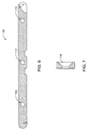
Figures 4-6 are front, bottom, and cross-sectional views, respectively, of a side rail that was subjected to tests described herein. -
Figure 7 is a cross-sectional view of a mounting hole of the test side rail ofFigures 4-6 . -
Figures 8-11 are diagrams of test setups used to perform deflection tests on the test side rail ofFigures 4-6 . -
Figure 12 is a diagram of a test setup used to perform an impact test on the test side rail ofFigures 4-6 . -
Figure 13 is a top view of a portion of a medical table that includes force absorbing members disposed between a side rail and standoffs off the table. - Medical tables (e.g., operating tables) can include side rails that serve as mounting points for accessories (e.g., surgical accessories). The side rails described herein are made of materials that permit them to withstand impacts (e.g., as a result of the operating tables colliding with other objects) without permanently deforming as a result of the impact.
- Referring to
Figure 1 , a medical table (e.g., operating table) 100 includes a patient support surface (e.g., a table top assembly) 102 made of three support surface segments (e.g., table top components) 104. Thesupport surface segments 104 are configured to move relative to one another to adapt thepatient support surface 102 to various desired operating table orientations. The various operating table orientations can depend on specific procedures that a patient on the table 100 is to undergo. Thesupport surface segments 104 are attached to asupport base 108 that can control the movement and orientation of thesupport surface segments 104 relative to one another. For example, thesupport base 108 can include movement devices (e.g., electromechanical or pneumatic drives) connected to thesupport surface segments 104 and a control unit that is in communication with the movement devices and that is configured to control the movement of thesupport surface segments 104. - Each
support surface segment 104 includes aside rail 106 secured (e.g., fastened) to a side region of thesupport surface segment 104 to provide a mounting location for accessories, such as a surgical accessory. WhileFigure 1 only shows the side rails 106 extending from the left sides of thesupport surface segments 104, it should be understood that each of thesupport surface segments 104 typically includes aside rail 106 on both of its sides. Examples of surgical accessories include tool holders (e.g., surgical tool holders), patient support apparatuses (e.g., headrests, lateral patient supports, arm boards, knee crutches), and other medical accessories. Aheadrest 109 is shown attached to the table 100 inFigure 1 . As shown, the accessory (patient headrest) 109 can be secured to one of the side rails 106. Using the side rails 106, theaccessory 109 can be arranged (e.g., slid) onto the side rails 106, positioned at a desired location relative to the operating table 100, and then secured (e.g., fastened) to theside rail 106. Theaccessory 109 can also be released (e.g., loosened) from theside rail 106, repositioned (e.g., slid) along theside rail 106 to a next, alternative location based on the various needs of the patient or the operating room staff, and then re-secured to the side rails 106. - The side rails 106 are fastened to the
support surface segment 104 using spacers (e.g., standoffs) such that the side rails 106 are spaced from thesupport surface segment 104. The spacing from thesupport surface segment 104 is generally large enough to provide mounting clearance for the accessories to be mounted along theside rail 106. For example, the spacers (e.g., standoffs) can provide a spacing that is about 0.375 inch to about 1 inch (e.g., about 9,5 mm to about 25,4 mm) from thesupport surface segments 104. -
Figure 2 is a perspective view of one of the example side rails 106 of the table 100. Theside rail 106 includes anelongated member 110 that is configured to permit theaccessory 109 to be attached (e.g., releasably attached) for use. As discussed below, theelongated member 110 can be formed of a resilient elongated body that is coated (e.g., plated) with a harder material. The cross-sectional size and shape of theside rail 106 are typically chosen to conform to one or more regulatory or industry standards for the size and shape of operating table accessories. - As shown in
Figures 2 and 3 , theelongated member 110 has a generally rectangular cross-sectional shape having awidth 111 and aheight 113 to be received in a recess of an operating table accessory. Thewidth 111 of theelongated member 110 is typically about 6 mm to about 20 mm (e.g., about 8 mm to about 10 mm) and theheight 113 of theelongated member 110 is typically about 20 mm to about 35 mm (e.g., about 25 mm to about 30 mm). The size of theside rail 106 is anticipated to be suitably received within some standard operating room table accessories, such as standard accessories that are available and used in the U.S. - The
side rail 106 includes three mountingholes 112. The mountingholes 112 are sized and configured to structurally secure theside rail 106 to one of thesupport surface segments 104, using fasteners that pass through standoffs and into threaded holes in thesupport surface segments 104. The mountingholes 112 include recesses (e.g., countersunk recesses) 114 that are sized and configured to receive a portion (e.g., a fastener head) of the fasteners used to secure theside rail 106 to thesupport surface segment 104. Thecountersunk recess 114 is typically sized to receive the head of a fastener so that the head lies generally flush with anouter surface 116 of theside rail 106 so that the head of the fastener does not extend beyond theouter surface 116. For example, the mountingholes 112 and thecountersunk recesses 114 can be sized and configured to receive and accommodate a flat head cap screw, such as an M10 flat head cap screw. - The mounting
holes 112 are spaced apart along theside rail 106 by aninner spacing distance 118. The inner spacing distance is typically small enough to provide adequate structural support limiting the amount that theside rail 106 can flex or deflect during typical use, such as when forces are applied when theaccessory 109 is attached to theside rail 106 and supported during use. However, theinner spacing distance 118 is typically large enough so that theside rail 106 is able to flex as a result of impact forces, for example, if an object bumps into theside rail 106 on the operating table 100. Therefore, the desiredinner spacing distance 118 can be influenced by the size and shape (e.g., the height and width) of theside rail 106 and the materials from which portions of the side rail 106 (e.g., the elongated body and the plating of theelongated member 110 of the side rail 106) are made. Additionally, theinner spacing distance 118 between the mountingholes 112 can also be determined by regulatory agency specifications or by the manufacturer of the operating table on which theside rail 106 is used. Theinner spacing distance 118 is typically about 300 mm or less (e.g., about 50 mm to about 300 mm, about 100 mm to about 250 mm, about 130 mm to about 190 mm). - The mounting
holes 112 that are arranged closest to the ends of theside rail 106 are typically spaced apart from the ends of theside rail 106 by anouter spacing distance 120. Like theinner spacing distance 118, theouter spacing distance 120 is typically small enough to provide structural stability for anaccessory 109 secured near the end of theside rail 106 during use. However, theouter spacing distance 120 is typically large enough to permit the end of the side rail to flex, for example, when inadvertently bumped into by another piece of equipment. Theouter spacing distance 120 is typically about 150 mm or less (e.g., about 35 mm to about 150 mm, about 55 mm to about 90 mm). - The
side rail 106 can include accessory retention devices (e.g., an accessory lock) to help prevent accessories from sliding off of theside rail 106, for example, as a result of the table 100 moving. For example, as shown inFigure 2 , theside rail 106 includes a gravity controlledaccessory lock 122 to prevent an accessory from inadvertently sliding off of theside rail 106. Theaccessory lock 122 includes a pivotingfinger 124 that is able to swing inward towards theside rail 106, for example, as an accessory is slid onto theside rail 106. However, the pivotingfinger 124 is generally obstructed from swinging away from theside rail 106 beyond an angular position relative to a longitudinal axis of theside rail 106 that would permit an accessory to slide off of theside rail 106. For example, the pivotingfinger 124 shown is not able to pivot away from theside rail 106 beyond the orientation shown inFigure 1 (e.g., about 90 degrees relative to the longitudinal axis of the side rail 106). During use, an accessory may be slid onto theside rail 106 and the pivotingfinger 124 swings upward towards theside rail 106 to pass through an opening of the accessory. However, if the accessory is inadvertently slid towards the end of theside rail 106, thehanging pivoting finger 124, which would fall downward under the force of gravity after the accessory is slid beyond the pivotingfinger 124, would block the accessory from falling off theside rail 106. If a user wanted to remove the accessory, the pivotingfinger 124 can be manually pivoted into theside rail 106 and the accessory can be removed. - As noted above, the
elongated member 110 of theside rail 106 is typically formed of an elongated resilient body that is plated with a different (e.g., harder) material than the material of the elongated body. Theelongated member 110 provides suitable structural strength to support thevarious accessories 109 that are secured to theside rail 106 during use, but is also generally able to withstand an impact force (e.g., as a result of an inadvertent collision with another object) without permanently deforming. To withstand impact forces, the material of the elongated body is generally resilient and flexible so that theside rail 106 can deflect under higher, impact loads, for example, side loads applied to theside rail 106. As a result of its flexibility and resilience, theside rail 106 is anticipated to be damaged (e.g., permanently deformed) less frequently, thus reducing required maintenance of the side rails 106 and the table 100 as a whole. For example, side rails made of materials having a modulus of elasticity , which is a measure of a material's stiffness, that is about 50 gigapascals ("GPa") to about 150 GPa have been shown to provide suitable flexibility in order to permit the side rail to deflect under most expected impact forces. - In combination with the flexibility of the
side rail 106 as a result of the lower modulus of elasticity, the material is also selected to have the ability to flex without permanently deforming. Therefore, the material has a high yield strength, which is a measure of the material's ability to resist plastic (e.g., permanent) deformation under stress. For example, side rails made of materials having a yield strength that is about 40 x 107 pascals ("Pa") to about 120 x 107 Pa have been shown to have suitable resistance to permanent deformation. - Materials that possess this combination of a relatively low modulus of elasticity permitting deflection under an applied force and a high yield strength limiting permanent deformation when deflected have been shown to exhibit superior impact performance over side rails made of certain conventional materials, such as stainless steels. Examples of materials that possess combinations of modulus of elasticity and yield strength within the above-referenced ranges include certain aluminums, such as aircraft aluminum (A1 7075-T6) and certain titaniums, such as Ti5 Titanium.
- As discussed above, the elongated body of the
elongated member 110 of the side rails 106 is typically plated with another harder material. The plated material can provide protection from and resistance to wear and corrosion of the underlying, inner material which can help increase durability of theside rail 106. For applying a suitably plated material to the elongated body that provides adequate wear and corrosion protection, the plated material is typically applied according to one or more regulatory standards, such as ASME plating standards. The elongated body is typically nickel plated. For example, the elongated body can be plated with a 0.025 mm thick electroless nickel medium phosphour plated material. -
Figures 4-7 illustrate a specific example of a side rail 106 (e.g., showing specific dimensions in mm) that was subjected to the testing to be described below. The testedside rail 106 was made of 7075-T6 Aluminum with a mid-phosphorus electroless nickel plating having a thickness of about 0.25 mm. The testedside rail 106 was manufactured to have a cross-sectional size and shape that conformed with typical side rail norms used in the U.S. Specifically, theside rail 106 was about 9.5 mm wide, about 28.6 mm high, and about 429 mm long. The three mountingholes 112 of the testedside rail 106 were longitudinally spaced apart by about 142.5 mm. The testedside rail 106 was subjected to a series of tests, including deflection tests and an impact test to analyze the side rail's ability to withstand various loads. - The tested
side rail 106 was deflection tested according to EN ISO 19054:2006. Summaries of the test procedures and the corresponding results for each of the deflection tests are provided below in Table 1. Instruments that were used during testing are described below in Table 2.Table 1 Test No. Test Procedure Results 1 The rail is supported along its narrow face by two supports centered relative to the rail and spaced 300 mm apart. Opposite to the face, a load of 500 N is applied on center in the downwards direction. a) Maximum deflection was measured to be 0.36 mm - PASS. b) No permanent deformation was observed after load was removed. 2 The rail is supported along its wide face by two supports centered relative to the rail and spaced 300 mm apart. Opposite to this face, a load of 500 N is applied on center in the downwards direction. a) Maximum deflection was measured to be 2.4 mm - PASS. b) No permanent deformation was observed after load was removed. 3 The rail is fully supported between two supports spaced 300 mm apart. A torque load of 150 N-m along the axis of the rail is applied centered between the two supports. a) Maximum deflection angle was measured to be 4 degrees - PASS. b) No permanent deformation was observed after load was removed. 4 The rail is fully supported on one end only resulting in a cantilevered rail that is 150 mm long. A load of 250 N is applied at the end of the cantilevered rail in a direction normal to the narrow face of the rail. a) Maximum deflection was measured to be 1.5 mm. b) No permanent deformation was observed after load was removed. 5 The rail is fully supported on one end only resulting in a cantilevered rail that is 150 mm long. A load of 250 N is applied at the end of the cantilevered rail in a direction normal to the wide face of the rail. a) Maximum deflection was measured to be 3.5 mm. b) No permanent deformation was observed after load was removed. 6 The rail is supported on one end only resulting in a cantilevered rail that is 150 mm long. A torque of 75 N-m is applied at the end of the cantilevered rail. a) Maximum deflection angle was measured to be 4 degrees - PASS. b) No permanent deformation was observed after load was removed. Table 2 Description Manufacturer and Model Serial Number Digital Calipers Mitutoyo CD-6"-CX 06170600 Height Gauge Grizzly - 12" Height N/A Digital Scale Rubbermaid 4040-88 4040-88-11405 Granite Inspection Table N/A N/A Inclinometer Dasco Pro-Angle Finder N/A -
Figure 8 illustrates atest setup 200 used to perform Tests 1 and 2. The digital scale was used to establish and verify a load input that would result in a consistent force of about 500 N output by anarbor press 202. A fixture was constructed such that the test side rail was supported by rail supports 204 separated by about 300 mm. Using the height gauge to measure change in the fixture height during loading, care was taken to help ensure that the fixture setup did not significantly deflect under the load. Little change (e.g., substantially no change) in height of the fixture setup was detected under the load. A gauge block 206 was placed under thetest side rail 106 in order to establish a consistent surface from which deflection measurements of thetest side rail 106 could be taken. Thetest side rail 106 was then subjected to a load of about 500 N applied to both the narrow and wide faces according to Test Procedures 1 and 2. Measurements of the resulting deflection were taken before, during, and after loading such that maximum deflection and rebound could be established. The deflection was measured using the height gauge and was confirmed using the digital calipers. As indicated in Table 1 above, for Test 1, the maximum deflection was 0.36 mm when the load was applied and no permanent deflection was observed in thetest side rail 106 when the load was released. For Test 2, the maximum deflection was 2.4 mm when the load was applied and no permanent deflection was observed in thetest side rail 106 when the load was released. -
Figure 9 illustrates atest setup 300 used to performTest 3. ForTest 3, thetest side rail 106 was supported between twovices 302 positioned about 300 mm apart from on another. Alarge cantilever arm 304 was affixed to the center of thetest side rail 106 and a torque load of about 150 N-m was applied to thetest side rail 106. An observed rail deflection angle under load was then measured with the inclinometer. As indicated in Table 1 above, the maximum deflection was 4 degrees when the load was applied and no permanent deflection was observed in thetest side rail 106 when the load was released. -
Figure 10 illustrates atest setup 400 used to perform Tests 4 and 5. Afixture 402 was developed such that thetest side rail 106 was securely constrained on one end and a free length of unsupported rail of about 150 mm was cantilevered outwards. A load of about 250 N was then applied at the very tip of the cantilevered test side rail. Any changes of the gap between thefixture 402 and thetest side rail 106 were measured before, during, and after loading such that observed deflection and rebound could be established. This setup was used to apply loads to both the narrow and wide faces of thetest side rail 106, according to Test Procedures 4 and 5 in Table 1. As indicated in Table 1 above, for Test 4, the maximum deflection was 1.5 mm when the load was applied and no permanent deflection was observed in thetest side rail 106 when the load was released. For Test 5, the maximum deflection was 3.5 mm when the load was applied and no permanent deflection was observed in thetest side rail 106 when the load was released. -
Figure 11 illustrates atest setup 500 used to performTest 6. Thetest side rail 106 was held in a cantilevered configuration such that about 150 mm of thetest side rail 106 extended from avice 502. A torque of about 75 N-m was then applied at the end of thetest side rail 106. Deflection of thetest side rail 106 that was observed before, during, and after loading was measured with the inclinometer such that angular deflection under load could be established. As indicated in Table 1 above, the maximum deflection was 4 degrees when the load was applied and no permanent deflection was observed in thetest side rail 106 when the load was released. - After completing all the tests, the
test side rail 106 was visually examined to verify that it was substantially free of permanent deformation. Thetest side rail 106 was also checked for flatness on the granite inspection table and showed no sign of deformation. - The test side rail was also impact tested, according to determine and compare the degree to which the test side rail, which was made of nickel plated 7075-T6 aluminum, and another test rail, which was made of conventional 304 stainless steel but had the same dimensions as the
test side rail 106, deform relative to one another when struck with substantially equivalent loads. A summary of the test procedure for the impact test of the test side rail are provided below in Table 3.Table 3 Test No. Test Procedure 1 A 120 mm cantilevered length of rail is struck on the end with a 2.25 kg mass dropped from a height of 75 cm. This impact is repeated five times for each sample rail. - Table 4 provides descriptions of respective test samples that were used during impact testing.
Table 4 Sample No. Description Material Composition 1 Aluminum ("A1.") Rail According to Figs. 4-7 7075-T6 Aluminum with Electroless Nickel Coating, Mid Phosphorus, .025 mm thick 2 Benchmark Stainless Steel ("S.S.") Rail 304 Stainless Steel -
Figure 12 illustrates atest setup 600 used to perform the impact testing. Sample 1, made of nickel plated 7075-T6 Aluminum, was clamped to alarge vice 602 such that 120 mm of unsupportedtest side rail 106 protruded outwards away from thevice 602. Amass 604 of 2.25 kilograms was suspended at a height of 75 cm from thetest side rail 106 and allowed to fall on the end of thetest side rail 106. Thetest side rail 106 was then inspected for deformation and the resulting maximum deformation of thetest side rail 106 was recorded. This process was then repeated a total of 5 times, noting additional increases in deformation after each impact. This process was then repeated for Sample 2, the stainless steel benchmark rail, which had substantially the same size and shape as Sample 1, the nickel plated 7075-T6 aluminum rail. - After completing each impact for both test side rail samples, the test side rails were examined for permanent deformation. The observed test results of the impact testing are provided below in Table 5. Note that the deformation data results provided in Table 5 were recorded as a change in geometry from one impact to the next impact and not the total observed impact.
Table 5 Impact No. Deformation of Aluminum. Rail Deformation of Stainless Steel Rail 1 0.86 mm 2.08 mm 2 0.40 mm 0.58 mm 3 0.05 mm 0.28 mm 4 0.02 mm 0.23 mm 5 0.18 mm 0.25 mm Average deformation per impact 0.30 mm 0.68 mm - When subjected to equivalent impact forces, Sample 2, the stainless steel rail, was shown to deform an average deformation distance per impact that was over twice as much as the deformation of Sample 1, the nickel plated 7075-T6 aluminum rail. This impact testing demonstrated that a side rail made of nickel plated 7075-T6 aluminum can absorb impact forces without permanently deforming better than certain conventional stainless steel side rails.
- While the side rails have been described as being fastened in a substantially rigid manner to the standoffs and, therefore, also to the table, other configurations are possible.
- As shown in
Figure 13 ,force absorbing members 126, such as springs (e.g., Belleville washers), are disposed between theside rail 106 and the table. As shown, each of the absorbingmembers 126 is disposed between theside rail 106 and one of thestandoffs 128. Alternatively, theforce absorbing members 126 can be disposed between thestandoffs 128 and the table 100. Theforce absorbing members 126 provide a resisting force that limits the extent that theside rail 106 can move relative to the table 100. Thus, an impact force applied to the side rail 106 (e.g., as a result of a collision) can be absorbed by theforce absorbing members 126 and theside rail 106 can move towards the table 100 without substantially deforming. - In some embodiments, the spring force constant of each absorbing
member 126 is about 50 N/mm to about 200 N/mm. In certain implementations, theside rail 106 equipped with theforce absorbing members 126 can withstand energy of about 5 Joules to about 100 Joules (e.g., resulting from an impact force) without experiencing permanent deformation. In some embodiments, theside rail 106 can withstand energy of about 50 Joules to about 100 Joules without experiencing permanent deformation. As an example, theside rail 106 could withstand the impact of a 2 kg mass weight dropped from a height of 1 meter (accelerating at 1 g) without experiencing permanent deformation. - While multiple
force absorbing members 126 have been described as being positioned along the side rail, in some embodiments, only one force absorbing member is used. The sole force absorbing member in such embodiments can be positioned on the center standoff. - While the side rail has been described as having a member that defines a generally rectangular cross-sectional shape, other configurations are possible. For example, in some embodiments, the side rail has a cross-sectional shape that is shaped as other polygons (e.g., trapezoids, triangles, pentagons, hexagons, or other polygons), curved shapes (e.g., circles, ellipses, oblong shapes), or other shapes, such as a C-channel, an I-beam, or non-uniform shapes having other curved and/or flat surfaces.
- While the side rail has been described as having three mounting holes, the side rail can have more or fewer mounting holes. For example, in some embodiments, the side rail has more than three (e.g., four, five, six, seven, eight, or more) mounting holes. In other embodiments, the side rail has fewer (e.g., two or one) mounting holes.
- While the side rail has been described as being attached to the table using fasteners arranged through mounting holes, other attachment devices or techniques can be used. For example, in some embodiments, the side rail is attached to the table using clips, snapping mechanisms, adhesives, welding, or other attachment devices or techniques.
- While the side rail has been described as having an accessory lock at one end that can prevent accessories from inadvertently sliding off the side rail, other configurations are possible. For example, in some embodiments, the side rail includes an accessory lock at both ends. In some embodiments, the side rail does not include an accessory lock.
- While the table has been described as including three patient support surface segments, other configurations are possible. For example, the table can include fewer (e.g., one or two) patient support segments or more (e.g., four, five, six, seven, or more) patient support surface segments to support the patient in a variety of operating room configurations.
Claims (15)
- A side rail (106) for a medical table, the side rail comprising:an elongated body having a height and a width that are configured to be received by a medical accessory (109), wherein the elongated body is formed of a material having a modulus of elasticity that is about 50 gigapascals to about 150 gigapascals and a yield strength that is about 40 x 107 pascals to about 120 x 107 pascals, wherein the height is about 25 mm to about 30 mm and the width is about 8 mm to about 10 mm.
- The side rail according to claim 1, wherein the height is about 28.6 mm and the width is about 9.5 mm.
- The side rail according to claim 1 or 2, wherein the material has a modulus of elasticity that is about 50 gigapascals to about 80 gigapascals and a yield strength that is about 40 x 107 pascals to about 60 x 107 pascals.
- The side rail according to claim 3, wherein the material is 7075-T6 Aluminum.
- The side rail according to claim 1 or 2, wherein the material has a modulus of elasticity that is about 100 gigapascals to about 130 gigapascals and a yield strength that is about 100 x 107 pascals to about 120 x 107 pascals.
- The side rail according to claim 5, wherein the material is Ti5 Titanium.
- The side rail according to any of the preceding claims, further comprising a metal plating that substantially covers the elongated body, the metal plating preferably comprising a nickel based material, more preferably an electroless nickel plating that is about 0.025 mm thick.
- The side rail according to any of the preceding claims, wherein when the side rail is supported along a first, wide side by two support members that are about 300 mm apart and a 500 newton force is applied midway between the support members to a second, opposite side of the side rail, a maximum deflection of in the side rail is less than about 5 mm, and when the force is released, the side rail rebounds and substantially no permanent deformation of the side rail occurs.
- The side rail according to claim 8, wherein the maximum deflection of the side rail is less than about 3.0 mm.
- The side rail according to any of the preceding claims, wherein the medical table is an operating room table.
- A medical table system comprising:a table (100) that is configured to support a patient during a medical procedure, the table defining a patient support surface (102);a side rail (106) according to any of claims 1 - 8 disposed along an outer surface of the table.
- A medical table system comprising:a table (100) that is configured to support a patient during a medical procedure, the table defining a patient support surface (102);a side rail (106) disposed along an outer surface of the table, the side rail comprising:an elongated body having a height and a width that are configured to be received by a medical accessory (109), wherein the height is about 25 mm to about 30 mm andthe width is about 8 mm to about 10 mm, the side rail being secured to the table using fasteners that pass through standoffs (108) and into threaded holes in support surface segments (104) of the table and using a force absorbing member (126) disposed between the side rail and one of the standoffs or between the standoffs and the table, that is configured to permit the side rail to deflect towards the table when energy of about 5 Joules to about 100 Joules is applied to the side rail in the form of an impact force and to absorb some of the energy applied to the side rail as the side rail deflects towards the table.
- The medical table system according to claim 12, wherein the force absorbing member provides a resisting force having a spring force constant that is about 50 N/mm to about 200 N/mm.
- The medical table system according to claim 12 or 13, wherein the force absorbing member is a spring, more preferably, a washer spring.
- The medical table system according to any of claims 11-14, wherein the table is an operating room table.
Applications Claiming Priority (2)
| Application Number | Priority Date | Filing Date | Title |
|---|---|---|---|
| US13/428,673 US9289343B2 (en) | 2012-03-23 | 2012-03-23 | Resilient side rails for medical tables |
| PCT/IB2013/000967 WO2013140260A2 (en) | 2012-03-23 | 2013-03-19 | Resilient side rails for medical tables |
Publications (2)
| Publication Number | Publication Date |
|---|---|
| EP2827823A2 EP2827823A2 (en) | 2015-01-28 |
| EP2827823B1 true EP2827823B1 (en) | 2016-07-27 |
Family
ID=48700627
Family Applications (1)
| Application Number | Title | Priority Date | Filing Date |
|---|---|---|---|
| EP13732222.8A Active EP2827823B1 (en) | 2012-03-23 | 2013-03-19 | Resilient side rails for medical tables |
Country Status (6)
| Country | Link |
|---|---|
| US (1) | US9289343B2 (en) |
| EP (1) | EP2827823B1 (en) |
| CN (1) | CN104244898B (en) |
| ES (1) | ES2600131T3 (en) |
| PL (1) | PL2827823T3 (en) |
| WO (1) | WO2013140260A2 (en) |
Families Citing this family (6)
| Publication number | Priority date | Publication date | Assignee | Title |
|---|---|---|---|---|
| US9289343B2 (en) * | 2012-03-23 | 2016-03-22 | Trumpf Medizin Systeme Gmbh + Co. Kg | Resilient side rails for medical tables |
| US8997281B2 (en) | 2012-03-23 | 2015-04-07 | Trumpf Medizin Systeme Gmbh + Co. Kg | Operating table top assemblies and related devices |
| CN104068984A (en) * | 2014-06-20 | 2014-10-01 | 玉林市科邦技术服务有限公司 | An anti-falling armrest for an operating table |
| US10583055B2 (en) * | 2015-10-26 | 2020-03-10 | Cornerstone Research Group, Inc. | Human stabilization platforms and related methods |
| DE102016207417A1 (en) * | 2016-04-29 | 2017-11-02 | Siemens Healthcare Gmbh | Rail guide with a locking unit, patient table with a rail guide for accessories and method for operating a rail guide |
| DE102017000851B4 (en) * | 2017-01-31 | 2020-12-10 | Drägerwerk AG & Co. KGaA | Flexible console system for medical devices |
Citations (1)
| Publication number | Priority date | Publication date | Assignee | Title |
|---|---|---|---|---|
| GB2269579A (en) * | 1992-08-14 | 1994-02-16 | John Richard Wickham Hardy | Waste product collection unit |
Family Cites Families (22)
| Publication number | Priority date | Publication date | Assignee | Title |
|---|---|---|---|---|
| US5628080A (en) * | 1994-08-10 | 1997-05-13 | Ohio Mattress Company Licensing And Components Group | Curve formed protective and decorative bedding foundation corner guard |
| DE69733095T2 (en) | 1996-10-23 | 2005-09-01 | Hill-Rom Services, Inc., Batesville | Integral side rail and accessory support device for a bed |
| US6470520B1 (en) | 1999-08-23 | 2002-10-29 | Hill-Rom Services, Inc. | Bed section attachment mechanism |
| JP2003534873A (en) * | 2000-06-05 | 2003-11-25 | ヒル−ロム サービシーズ,インコーポレイティド | Medical accessory support |
| DE10253877A1 (en) | 2002-11-12 | 2004-05-27 | Trumpf Medizin Systeme Gmbh | Plate-shaped device for supporting a body part of a patient |
| DE10253846A1 (en) | 2002-11-15 | 2004-06-03 | Trumpf Medizin Systeme Gmbh | operating table |
| DE10261759A1 (en) | 2002-12-19 | 2004-07-15 | Trumpf Medizin Systeme Gmbh | Patient table |
| DE10336303A1 (en) | 2003-07-31 | 2005-03-03 | Trumpf Medizin Systeme Gmbh | Method for transporting a patient support plate and transport device for carrying out the method |
| WO2005107676A1 (en) * | 2004-05-12 | 2005-11-17 | Surgipod Pty. Ltd. | Lateral support for an operating table |
| US20060103226A1 (en) | 2004-09-17 | 2006-05-18 | Wong George T | Medical table shoulder chair |
| DE102004047509B4 (en) | 2004-09-28 | 2007-02-01 | Siemens Ag | Fastening device for attaching an accessory to a patient bed |
| CA2487543A1 (en) * | 2004-11-10 | 2006-05-10 | Hill-Rom Services, Inc. | Siderail spring dampener |
| US7762444B2 (en) * | 2004-12-01 | 2010-07-27 | Avery Dennison Corporation | Tool for securing together two or more layers of a mattress using a plastic fastener |
| DE102005056275C5 (en) | 2005-11-14 | 2012-06-28 | Trumpf Medizin Systeme Gmbh | Operating table with a patient support plate |
| DE102005054174A1 (en) | 2005-11-14 | 2007-05-16 | Maquet Gmbh & Co Kg | Patient storage area for an operating table |
| FR2901122B1 (en) | 2006-05-18 | 2008-08-22 | Steris Surgical Technologies Sas | GUIDE DEVICE FOR OPERATING TABLE COMPRISING GUIDING ARMS SUITABLE TO BE FIXED REMOVABLY ON THE TABLE, AND OPERATING TABLE COMPRISING SUCH GUIDING ARMS |
| EP2020217B1 (en) | 2007-08-03 | 2011-04-27 | TRUMPF Medizin Systeme GmbH | Operating table |
| US8256047B2 (en) | 2008-04-03 | 2012-09-04 | Klemm Kurt W | Combination treatment device and an anterior support device |
| USD604422S1 (en) | 2008-07-30 | 2009-11-17 | Trumpf Medizin Systeme Gmbh | Patient-supporting panel of an operating table |
| DE202011000308U1 (en) | 2011-02-10 | 2011-04-21 | Maquet Gmbh & Co. Kg | extension device |
| US8997281B2 (en) * | 2012-03-23 | 2015-04-07 | Trumpf Medizin Systeme Gmbh + Co. Kg | Operating table top assemblies and related devices |
| US9289343B2 (en) * | 2012-03-23 | 2016-03-22 | Trumpf Medizin Systeme Gmbh + Co. Kg | Resilient side rails for medical tables |
-
2012
- 2012-03-23 US US13/428,673 patent/US9289343B2/en active Active
-
2013
- 2013-03-19 CN CN201380021042.7A patent/CN104244898B/en active Active
- 2013-03-19 ES ES13732222.8T patent/ES2600131T3/en active Active
- 2013-03-19 PL PL13732222T patent/PL2827823T3/en unknown
- 2013-03-19 WO PCT/IB2013/000967 patent/WO2013140260A2/en not_active Ceased
- 2013-03-19 EP EP13732222.8A patent/EP2827823B1/en active Active
Patent Citations (1)
| Publication number | Priority date | Publication date | Assignee | Title |
|---|---|---|---|---|
| GB2269579A (en) * | 1992-08-14 | 1994-02-16 | John Richard Wickham Hardy | Waste product collection unit |
Also Published As
| Publication number | Publication date |
|---|---|
| EP2827823A2 (en) | 2015-01-28 |
| WO2013140260A3 (en) | 2014-03-20 |
| CN104244898A (en) | 2014-12-24 |
| ES2600131T3 (en) | 2017-02-07 |
| CN104244898B (en) | 2016-05-25 |
| US20130247299A1 (en) | 2013-09-26 |
| PL2827823T3 (en) | 2017-01-31 |
| US9289343B2 (en) | 2016-03-22 |
| WO2013140260A2 (en) | 2013-09-26 |
Similar Documents
| Publication | Publication Date | Title |
|---|---|---|
| US9289343B2 (en) | Resilient side rails for medical tables | |
| US9251720B2 (en) | Trunk skeleton of human body dummy | |
| CN207636420U (en) | A kind of tooling of spring fatigue test | |
| US20190254418A1 (en) | Height-adjustable table having reinforced table top | |
| CN102346091A (en) | Drop Test Device | |
| ES2309014T3 (en) | DEVICE FOR SETTING COUNTERWEIGHTS FOR BALANCE. | |
| PT674050E (en) | ROLLER SUPPORT FOR A NEEDLE PLATE ADDED TO A BRIDGE ROOF | |
| KR101301761B1 (en) | Impact machine device using restoring force | |
| US20200182732A1 (en) | Gravity pendulum, adapter and holder | |
| CN215635902U (en) | Cardiovascular detection device convenient to multi-angle display | |
| CN209387125U (en) | A kind of detection lathe and its device for detecting part intrinsic frequency | |
| CN215984377U (en) | Steel structure clamping device for strain gauge testing steel structure strain | |
| CN107752519B (en) | A kind of movable seat chair form buffer mechanism | |
| CN108801811A (en) | A kind of paint paint film impact test instrument | |
| CN213364186U (en) | Gauge block impact testing device | |
| US8950553B2 (en) | Safety bar | |
| KR200460221Y1 (en) | A portable jig for hardness test | |
| US8297105B2 (en) | Impact testing device and impact testing method using the same | |
| CN214095815U (en) | Checking fixture for positioning automobile rear gear glass | |
| CN208366311U (en) | A kind of three apparatus of coordinate detecting of semiconductor | |
| CN223413080U (en) | An adjustable fixing mechanism for metal hardness testing | |
| CN219715086U (en) | Panel intensity detects test bench | |
| CN222258580U (en) | A pressure calibration device for chemical instruments | |
| CN214224512U (en) | Detection equipment for dental rotary tool | |
| CN218068063U (en) | Extension formula is convenient for experimental testing arrangement of electric power that supports |
Legal Events
| Date | Code | Title | Description |
|---|---|---|---|
| PUAI | Public reference made under article 153(3) epc to a published international application that has entered the european phase |
Free format text: ORIGINAL CODE: 0009012 |
|
| 17P | Request for examination filed |
Effective date: 20141022 |
|
| AK | Designated contracting states |
Kind code of ref document: A2 Designated state(s): AL AT BE BG CH CY CZ DE DK EE ES FI FR GB GR HR HU IE IS IT LI LT LU LV MC MK MT NL NO PL PT RO RS SE SI SK SM TR |
|
| AX | Request for extension of the european patent |
Extension state: BA ME |
|
| RIN1 | Information on inventor provided before grant (corrected) |
Inventor name: DALEY, EDWARD Inventor name: SCHLEITZER, PATRICK Inventor name: SOTO, ORLANDO |
|
| DAX | Request for extension of the european patent (deleted) | ||
| 17Q | First examination report despatched |
Effective date: 20150806 |
|
| GRAP | Despatch of communication of intention to grant a patent |
Free format text: ORIGINAL CODE: EPIDOSNIGR1 |
|
| INTG | Intention to grant announced |
Effective date: 20160216 |
|
| GRAS | Grant fee paid |
Free format text: ORIGINAL CODE: EPIDOSNIGR3 |
|
| GRAA | (expected) grant |
Free format text: ORIGINAL CODE: 0009210 |
|
| AK | Designated contracting states |
Kind code of ref document: B1 Designated state(s): AL AT BE BG CH CY CZ DE DK EE ES FI FR GB GR HR HU IE IS IT LI LT LU LV MC MK MT NL NO PL PT RO RS SE SI SK SM TR |
|
| REG | Reference to a national code |
Ref country code: GB Ref legal event code: FG4D |
|
| REG | Reference to a national code |
Ref country code: CH Ref legal event code: EP |
|
| REG | Reference to a national code |
Ref country code: AT Ref legal event code: REF Ref document number: 815195 Country of ref document: AT Kind code of ref document: T Effective date: 20160815 |
|
| REG | Reference to a national code |
Ref country code: IE Ref legal event code: FG4D |
|
| REG | Reference to a national code |
Ref country code: DE Ref legal event code: R096 Ref document number: 602013009887 Country of ref document: DE |
|
| REG | Reference to a national code |
Ref country code: SE Ref legal event code: TRGR |
|
| REG | Reference to a national code |
Ref country code: LT Ref legal event code: MG4D |
|
| REG | Reference to a national code |
Ref country code: NL Ref legal event code: MP Effective date: 20160727 |
|
| REG | Reference to a national code |
Ref country code: AT Ref legal event code: MK05 Ref document number: 815195 Country of ref document: AT Kind code of ref document: T Effective date: 20160727 |
|
| PG25 | Lapsed in a contracting state [announced via postgrant information from national office to epo] |
Ref country code: IS Free format text: LAPSE BECAUSE OF FAILURE TO SUBMIT A TRANSLATION OF THE DESCRIPTION OR TO PAY THE FEE WITHIN THE PRESCRIBED TIME-LIMIT Effective date: 20161127 Ref country code: NO Free format text: LAPSE BECAUSE OF FAILURE TO SUBMIT A TRANSLATION OF THE DESCRIPTION OR TO PAY THE FEE WITHIN THE PRESCRIBED TIME-LIMIT Effective date: 20161027 Ref country code: RS Free format text: LAPSE BECAUSE OF FAILURE TO SUBMIT A TRANSLATION OF THE DESCRIPTION OR TO PAY THE FEE WITHIN THE PRESCRIBED TIME-LIMIT Effective date: 20160727 Ref country code: FI Free format text: LAPSE BECAUSE OF FAILURE TO SUBMIT A TRANSLATION OF THE DESCRIPTION OR TO PAY THE FEE WITHIN THE PRESCRIBED TIME-LIMIT Effective date: 20160727 Ref country code: NL Free format text: LAPSE BECAUSE OF FAILURE TO SUBMIT A TRANSLATION OF THE DESCRIPTION OR TO PAY THE FEE WITHIN THE PRESCRIBED TIME-LIMIT Effective date: 20160727 Ref country code: LT Free format text: LAPSE BECAUSE OF FAILURE TO SUBMIT A TRANSLATION OF THE DESCRIPTION OR TO PAY THE FEE WITHIN THE PRESCRIBED TIME-LIMIT Effective date: 20160727 Ref country code: HR Free format text: LAPSE BECAUSE OF FAILURE TO SUBMIT A TRANSLATION OF THE DESCRIPTION OR TO PAY THE FEE WITHIN THE PRESCRIBED TIME-LIMIT Effective date: 20160727 |
|
| REG | Reference to a national code |
Ref country code: ES Ref legal event code: FG2A Ref document number: 2600131 Country of ref document: ES Kind code of ref document: T3 Effective date: 20170207 |
|
| REG | Reference to a national code |
Ref country code: FR Ref legal event code: PLFP Year of fee payment: 5 |
|
| PG25 | Lapsed in a contracting state [announced via postgrant information from national office to epo] |
Ref country code: AT Free format text: LAPSE BECAUSE OF FAILURE TO SUBMIT A TRANSLATION OF THE DESCRIPTION OR TO PAY THE FEE WITHIN THE PRESCRIBED TIME-LIMIT Effective date: 20160727 Ref country code: PT Free format text: LAPSE BECAUSE OF FAILURE TO SUBMIT A TRANSLATION OF THE DESCRIPTION OR TO PAY THE FEE WITHIN THE PRESCRIBED TIME-LIMIT Effective date: 20161128 Ref country code: LV Free format text: LAPSE BECAUSE OF FAILURE TO SUBMIT A TRANSLATION OF THE DESCRIPTION OR TO PAY THE FEE WITHIN THE PRESCRIBED TIME-LIMIT Effective date: 20160727 Ref country code: GR Free format text: LAPSE BECAUSE OF FAILURE TO SUBMIT A TRANSLATION OF THE DESCRIPTION OR TO PAY THE FEE WITHIN THE PRESCRIBED TIME-LIMIT Effective date: 20161028 Ref country code: BE Free format text: LAPSE BECAUSE OF FAILURE TO SUBMIT A TRANSLATION OF THE DESCRIPTION OR TO PAY THE FEE WITHIN THE PRESCRIBED TIME-LIMIT Effective date: 20160727 |
|
| PG25 | Lapsed in a contracting state [announced via postgrant information from national office to epo] |
Ref country code: EE Free format text: LAPSE BECAUSE OF FAILURE TO SUBMIT A TRANSLATION OF THE DESCRIPTION OR TO PAY THE FEE WITHIN THE PRESCRIBED TIME-LIMIT Effective date: 20160727 Ref country code: RO Free format text: LAPSE BECAUSE OF FAILURE TO SUBMIT A TRANSLATION OF THE DESCRIPTION OR TO PAY THE FEE WITHIN THE PRESCRIBED TIME-LIMIT Effective date: 20160727 |
|
| REG | Reference to a national code |
Ref country code: DE Ref legal event code: R097 Ref document number: 602013009887 Country of ref document: DE |
|
| PG25 | Lapsed in a contracting state [announced via postgrant information from national office to epo] |
Ref country code: SK Free format text: LAPSE BECAUSE OF FAILURE TO SUBMIT A TRANSLATION OF THE DESCRIPTION OR TO PAY THE FEE WITHIN THE PRESCRIBED TIME-LIMIT Effective date: 20160727 Ref country code: DK Free format text: LAPSE BECAUSE OF FAILURE TO SUBMIT A TRANSLATION OF THE DESCRIPTION OR TO PAY THE FEE WITHIN THE PRESCRIBED TIME-LIMIT Effective date: 20160727 Ref country code: SM Free format text: LAPSE BECAUSE OF FAILURE TO SUBMIT A TRANSLATION OF THE DESCRIPTION OR TO PAY THE FEE WITHIN THE PRESCRIBED TIME-LIMIT Effective date: 20160727 Ref country code: CZ Free format text: LAPSE BECAUSE OF FAILURE TO SUBMIT A TRANSLATION OF THE DESCRIPTION OR TO PAY THE FEE WITHIN THE PRESCRIBED TIME-LIMIT Effective date: 20160727 Ref country code: BG Free format text: LAPSE BECAUSE OF FAILURE TO SUBMIT A TRANSLATION OF THE DESCRIPTION OR TO PAY THE FEE WITHIN THE PRESCRIBED TIME-LIMIT Effective date: 20161027 |
|
| PLBE | No opposition filed within time limit |
Free format text: ORIGINAL CODE: 0009261 |
|
| STAA | Information on the status of an ep patent application or granted ep patent |
Free format text: STATUS: NO OPPOSITION FILED WITHIN TIME LIMIT |
|
| 26N | No opposition filed |
Effective date: 20170502 |
|
| PG25 | Lapsed in a contracting state [announced via postgrant information from national office to epo] |
Ref country code: SI Free format text: LAPSE BECAUSE OF FAILURE TO SUBMIT A TRANSLATION OF THE DESCRIPTION OR TO PAY THE FEE WITHIN THE PRESCRIBED TIME-LIMIT Effective date: 20160727 |
|
| REG | Reference to a national code |
Ref country code: CH Ref legal event code: PL |
|
| PG25 | Lapsed in a contracting state [announced via postgrant information from national office to epo] |
Ref country code: MC Free format text: LAPSE BECAUSE OF FAILURE TO SUBMIT A TRANSLATION OF THE DESCRIPTION OR TO PAY THE FEE WITHIN THE PRESCRIBED TIME-LIMIT Effective date: 20160727 |
|
| REG | Reference to a national code |
Ref country code: IE Ref legal event code: MM4A |
|
| PG25 | Lapsed in a contracting state [announced via postgrant information from national office to epo] |
Ref country code: LU Free format text: LAPSE BECAUSE OF NON-PAYMENT OF DUE FEES Effective date: 20170319 |
|
| REG | Reference to a national code |
Ref country code: FR Ref legal event code: PLFP Year of fee payment: 6 |
|
| PG25 | Lapsed in a contracting state [announced via postgrant information from national office to epo] |
Ref country code: CH Free format text: LAPSE BECAUSE OF NON-PAYMENT OF DUE FEES Effective date: 20170331 Ref country code: IE Free format text: LAPSE BECAUSE OF NON-PAYMENT OF DUE FEES Effective date: 20170319 Ref country code: LI Free format text: LAPSE BECAUSE OF NON-PAYMENT OF DUE FEES Effective date: 20170331 |
|
| PGFP | Annual fee paid to national office [announced via postgrant information from national office to epo] |
Ref country code: SE Payment date: 20180226 Year of fee payment: 6 Ref country code: PL Payment date: 20180221 Year of fee payment: 6 |
|
| PGFP | Annual fee paid to national office [announced via postgrant information from national office to epo] |
Ref country code: ES Payment date: 20180403 Year of fee payment: 6 |
|
| PG25 | Lapsed in a contracting state [announced via postgrant information from national office to epo] |
Ref country code: MT Free format text: LAPSE BECAUSE OF NON-PAYMENT OF DUE FEES Effective date: 20170319 |
|
| PG25 | Lapsed in a contracting state [announced via postgrant information from national office to epo] |
Ref country code: AL Free format text: LAPSE BECAUSE OF FAILURE TO SUBMIT A TRANSLATION OF THE DESCRIPTION OR TO PAY THE FEE WITHIN THE PRESCRIBED TIME-LIMIT Effective date: 20160727 |
|
| PG25 | Lapsed in a contracting state [announced via postgrant information from national office to epo] |
Ref country code: HU Free format text: LAPSE BECAUSE OF FAILURE TO SUBMIT A TRANSLATION OF THE DESCRIPTION OR TO PAY THE FEE WITHIN THE PRESCRIBED TIME-LIMIT; INVALID AB INITIO Effective date: 20130319 |
|
| REG | Reference to a national code |
Ref country code: SE Ref legal event code: EUG |
|
| PG25 | Lapsed in a contracting state [announced via postgrant information from national office to epo] |
Ref country code: CY Free format text: LAPSE BECAUSE OF FAILURE TO SUBMIT A TRANSLATION OF THE DESCRIPTION OR TO PAY THE FEE WITHIN THE PRESCRIBED TIME-LIMIT Effective date: 20160727 Ref country code: SE Free format text: LAPSE BECAUSE OF NON-PAYMENT OF DUE FEES Effective date: 20190320 |
|
| PG25 | Lapsed in a contracting state [announced via postgrant information from national office to epo] |
Ref country code: MK Free format text: LAPSE BECAUSE OF FAILURE TO SUBMIT A TRANSLATION OF THE DESCRIPTION OR TO PAY THE FEE WITHIN THE PRESCRIBED TIME-LIMIT Effective date: 20160727 |
|
| PG25 | Lapsed in a contracting state [announced via postgrant information from national office to epo] |
Ref country code: TR Free format text: LAPSE BECAUSE OF FAILURE TO SUBMIT A TRANSLATION OF THE DESCRIPTION OR TO PAY THE FEE WITHIN THE PRESCRIBED TIME-LIMIT Effective date: 20160727 |
|
| REG | Reference to a national code |
Ref country code: ES Ref legal event code: FD2A Effective date: 20200727 |
|
| PG25 | Lapsed in a contracting state [announced via postgrant information from national office to epo] |
Ref country code: ES Free format text: LAPSE BECAUSE OF NON-PAYMENT OF DUE FEES Effective date: 20190320 |
|
| PG25 | Lapsed in a contracting state [announced via postgrant information from national office to epo] |
Ref country code: PL Free format text: LAPSE BECAUSE OF NON-PAYMENT OF DUE FEES Effective date: 20190319 |
|
| PGFP | Annual fee paid to national office [announced via postgrant information from national office to epo] |
Ref country code: FR Payment date: 20250219 Year of fee payment: 13 |
|
| PGFP | Annual fee paid to national office [announced via postgrant information from national office to epo] |
Ref country code: GB Payment date: 20260220 Year of fee payment: 14 |
|
| PGFP | Annual fee paid to national office [announced via postgrant information from national office to epo] |
Ref country code: DE Payment date: 20260219 Year of fee payment: 14 |
|
| PGFP | Annual fee paid to national office [announced via postgrant information from national office to epo] |
Ref country code: IT Payment date: 20260219 Year of fee payment: 14 |