EP2827316A1 - Driver assistance - Google Patents
Driver assistance Download PDFInfo
- Publication number
- EP2827316A1 EP2827316A1 EP13176508.3A EP13176508A EP2827316A1 EP 2827316 A1 EP2827316 A1 EP 2827316A1 EP 13176508 A EP13176508 A EP 13176508A EP 2827316 A1 EP2827316 A1 EP 2827316A1
- Authority
- EP
- European Patent Office
- Prior art keywords
- vehicle
- driver assistance
- driver
- image data
- operational parameter
- Prior art date
- Legal status (The legal status is an assumption and is not a legal conclusion. Google has not performed a legal analysis and makes no representation as to the accuracy of the status listed.)
- Granted
Links
Images


Classifications
-
- G—PHYSICS
- G08—SIGNALLING
- G08G—TRAFFIC CONTROL SYSTEMS
- G08G1/00—Traffic control systems for road vehicles
- G08G1/16—Anti-collision systems
- G08G1/161—Decentralised systems, e.g. inter-vehicle communication
- G08G1/163—Decentralised systems, e.g. inter-vehicle communication involving continuous checking
-
- B—PERFORMING OPERATIONS; TRANSPORTING
- B60—VEHICLES IN GENERAL
- B60K—ARRANGEMENT OR MOUNTING OF PROPULSION UNITS OR OF TRANSMISSIONS IN VEHICLES; ARRANGEMENT OR MOUNTING OF PLURAL DIVERSE PRIME-MOVERS IN VEHICLES; AUXILIARY DRIVES FOR VEHICLES; INSTRUMENTATION OR DASHBOARDS FOR VEHICLES; ARRANGEMENTS IN CONNECTION WITH COOLING, AIR INTAKE, GAS EXHAUST OR FUEL SUPPLY OF PROPULSION UNITS IN VEHICLES
- B60K35/00—Instruments specially adapted for vehicles; Arrangement of instruments in or on vehicles
- B60K35/20—Output arrangements, i.e. from vehicle to user, associated with vehicle functions or specially adapted therefor
- B60K35/29—Instruments characterised by the way in which information is handled, e.g. showing information on plural displays or prioritising information according to driving conditions
-
- G—PHYSICS
- G08—SIGNALLING
- G08G—TRAFFIC CONTROL SYSTEMS
- G08G1/00—Traffic control systems for road vehicles
- G08G1/16—Anti-collision systems
- G08G1/161—Decentralised systems, e.g. inter-vehicle communication
- G08G1/162—Decentralised systems, e.g. inter-vehicle communication event-triggered
-
- G—PHYSICS
- G08—SIGNALLING
- G08G—TRAFFIC CONTROL SYSTEMS
- G08G1/00—Traffic control systems for road vehicles
- G08G1/22—Platooning, i.e. convoy of communicating vehicles
-
- B—PERFORMING OPERATIONS; TRANSPORTING
- B60—VEHICLES IN GENERAL
- B60K—ARRANGEMENT OR MOUNTING OF PROPULSION UNITS OR OF TRANSMISSIONS IN VEHICLES; ARRANGEMENT OR MOUNTING OF PLURAL DIVERSE PRIME-MOVERS IN VEHICLES; AUXILIARY DRIVES FOR VEHICLES; INSTRUMENTATION OR DASHBOARDS FOR VEHICLES; ARRANGEMENTS IN CONNECTION WITH COOLING, AIR INTAKE, GAS EXHAUST OR FUEL SUPPLY OF PROPULSION UNITS IN VEHICLES
- B60K2360/00—Indexing scheme associated with groups B60K35/00 or B60K37/00 relating to details of instruments or dashboards
- B60K2360/18—Information management
- B60K2360/191—Highlight information
-
- B—PERFORMING OPERATIONS; TRANSPORTING
- B60—VEHICLES IN GENERAL
- B60W—CONJOINT CONTROL OF VEHICLE SUB-UNITS OF DIFFERENT TYPE OR DIFFERENT FUNCTION; CONTROL SYSTEMS SPECIALLY ADAPTED FOR HYBRID VEHICLES; ROAD VEHICLE DRIVE CONTROL SYSTEMS FOR PURPOSES NOT RELATED TO THE CONTROL OF A PARTICULAR SUB-UNIT
- B60W2556/00—Input parameters relating to data
- B60W2556/45—External transmission of data to or from the vehicle
- B60W2556/65—Data transmitted between vehicles
-
- B—PERFORMING OPERATIONS; TRANSPORTING
- B60—VEHICLES IN GENERAL
- B60W—CONJOINT CONTROL OF VEHICLE SUB-UNITS OF DIFFERENT TYPE OR DIFFERENT FUNCTION; CONTROL SYSTEMS SPECIALLY ADAPTED FOR HYBRID VEHICLES; ROAD VEHICLE DRIVE CONTROL SYSTEMS FOR PURPOSES NOT RELATED TO THE CONTROL OF A PARTICULAR SUB-UNIT
- B60W30/00—Purposes of road vehicle drive control systems not related to the control of a particular sub-unit, e.g. of systems using conjoint control of vehicle sub-units
- B60W30/18—Propelling the vehicle
- B60W30/18009—Propelling the vehicle related to particular drive situations
- B60W30/18163—Lane change; Overtaking manoeuvres
Definitions
- Various embodiments relate to techniques of providing driver assistance for a driver of a vehicle.
- various techniques relate to receiving image data of a forward-view camera of a preceding vehicle and to receiving at least one movement value of the preceding vehicle.
- the wireless data connection can be according to the car-to-car (car2car) data communication standard. It is also known to exchange data between vehicles by means of the wireless local area network (WLAN) data communication standard.
- WLAN wireless local area network
- the wireless data connection it is known to exchange operational parameters between the vehicles via the wireless data connection.
- applications of driver assistance can be realized which provide diver assistance and/or warning functionality, e.g. to all vehicles which are located within the vicinity.
- the vicinity may be defined in terms of a transmission range of the wireless data connection.
- a method of providing driver assistance for a driver or a second vehicle by wirelessly receiving at least one operational parameter of a first vehicle is provided.
- the first vehicle is ahead of the second vehicle.
- the method comprises determining whether the first vehicle and the second vehicle move in immediate succession.
- the method further comprises, in dependence of the determining: the second vehicle selectively receiving the at least one operational parameter from the first vehicle.
- the method further comprises, based on the at least one operational parameter, providing the driver assistance.
- the first vehicle and the second vehicle moving in immediate succession may relate to the first vehicle driving directly ahead of the second vehicle.
- the first vehicle and the second vehicle moving in immediate succession may relate to no further vehicle being in between the first and second vehicles.
- the first and second vehicles may drive on the same road and may drive in the same direction.
- the at least one operation parameter may be received via a wireless data connection established between the first and second vehicles.
- the wireless data connection may be according to the WLAN standard and / or according to the car2car standard.
- Other examples of the wireless data connection may include: Bluetooth, Near Field Communication, mobile telephony network, etc.
- the method may further comprise: in response to the determining, selectively establishing the wireless data connection if the first and second vehicles move in immediate succession. E.g., for this establishing of the wireless data connection, position data of the first vehicle and/or the second vehicle may be exchanged between the first and second vehicles.
- the position data may be determined using a vehicle navigation system.
- the second vehicle is configured to determine an identification number of the first vehicle from image data which is obtained from a forward-view camera of the second vehicle.
- the identification number can at least partly correspond to a license plate number of the first vehicle which may be obtained, e.g., via image analysis of the obtained image data which images the license plate of the first vehicle.
- the identification number corresponds to a machine readable code which is obtained from markers and/or relates to a light pulse sequence emitted by a light source arranged on a read part of the first vehicle. Then the second vehicle may broadcast a wireless data connection request which at least partly includes the determined identification number of the first vehicle.
- the second vehicle may further receive a wireless data connection reply which may, e.g., be sent by the first vehicle in response to receiving the wireless data connection request.
- the wireless data connection reply may comprise at least parts of the identification number of the first vehicle, e.g., parts which had been missing in the wireless data connection request. Further, the wireless data connection reply may optionally comprise at least parts of an identification number of the second vehicle. Then, in response to the receiving of the wireless data connection reply, the second vehicle and / or the first vehicle may participate in the establishing of the wireless data connection between the first and second vehicles.
- the determining whether the first vehicle and the second vehicle move in immediate succession may at least comprise optical verification of the movement in succession.
- the driver assistance may relate to an application which particularly relies on the scenario of the first and second vehicles moving in immediate succession.
- the operational parameter may correspond to image data of a forward-view camera of the first vehicle.
- the providing of the driver assistance may include displaying at least parts of the image data on a display.
- a driver of the second vehicle may see what is ahead of the first vehicle which, in turn, is driving ahead of the second vehicle.
- obstructions and/or dangerous situations on the road ahead of the first and second vehicles may be detected comparably early by the driver of the second vehicle.
- the safety in driving may increase. Obstacles on the road, which would be otherwise hidden, e.g., by curvature of the road and / or the first vehicle itself, may become visible to the driver of the second vehicle from the displaying of the at least parts of the image data on the display.
- the display may be a Liquid Crystal Display (LCD) fixedly installed in the second vehicle, a head up display, and / or a display of a portable device which may be connected with a vehicle head unit of the second vehicle, etc.
- LCD Liquid Crystal Display
- the image data of the forward-view camera of the first vehicle may be encoded as digital data.
- the image data may be compressed in order to reduce the amount of data to be transmitted via the wireless data connection.
- the image data of the forward-view camera of the first vehicle received by the second vehicle may correspond to moving images, i.e., a movie.
- a refresh rate of the image data which is received by the second vehicle may be less than a refresh rate of the image data being originally obtained by the forward-view camera of the first vehicle.
- a comparably short amount of time may elapse between obtaining of the image data by the forward-view camera of the first vehicle and the displaying of the at least parts of the image data on the display of the second vehicle.
- the short amount of time may relate to a substantially real-time playback, i.e., less than 1 second, or less than 0.5 seconds, or even shorter times.
- the method may further comprise establishing whether a passing of the first vehicle by the second vehicle is desired.
- the displaying and/or the selectively receiving may further depend on the establishing whether the passing of the first vehicle by the second vehicle is desired.
- the driver assistance may be provided in the form of the displaying of the at least parts of the image data on the display of the second vehicle. Then it may be possible for the driver of the second vehicle to base the decision whether to pass the first vehicle on the extended viewing range achieved via the displayed image data. For example, if oncoming traffic is visible in the image data, a warning may be additionally issued and the driver of the second vehicle may postpone the passing the first vehicle. All this may increase traffic safety.
- the establishing whether the passing of the first vehicle by the second vehicle is desired can be based on user input, i.e., occur manually. However, it may also be possible that the establishing occurs automatically.
- the establishing whether the passing of the first vehicle by the second vehicle is desired may be based on elements selected from the group comprising: a curviness of a road on which the second vehicle travels; a current velocity of the second vehicle; a historic velocity of the second vehicle; a distance between the second vehicle and the first vehicle; a distance to an upcoming curve on the road on which the second vehicle travels; traffic signs detected based on the image data of the forward-view camera of the first vehicle and/or based on further image data of a forward-view camera of the second vehicle; opposing traffic detected based on the image data of the forward-view camera of the first vehicle and / or based on the further image data of the forward-view camera of the second vehicle; lane markings of the road detected based on the image data of the forward-view camera of the first vehicle and
- decision criterions in view of the above-mentioned factors influencing the establishing are given below; however, these decision criterions are merely examples and are not to be construed as being limiting: E.g., if the curviness of the road on which the second vehicle travels is smaller (larger) than a threshold, it may be established that the passing of the first vehicle is (not) desired. E.g., if the current velocity of the second vehicle is equal or above (below) the historic velocity of the second vehicle, e.g., on the particular road type of the road on which the second vehicle travels, it may be established that the passing is (not) desired.
- a moving window may be employed for averaging when determining the historic velocity.
- a human machine interface may prompt the user whether he intends to pass the first vehicle which is driving ahead. Then, in response to the user input and/or various of the above-mentioned criteria being fulfilled, the driver assistance in form of the displaying of the image data may be provided.
- HMI human machine interface
- the above-mentioned techniques may have the effect that the driver assistance is provided in a selective manner. E.g., only if the passing of the first vehicle becomes comparably likely, i.e., if a likelihood exceeds a predefined threshold, the driver assistance in the form of the displaying of the image data may be provided. All this may reduce a workload imposed on the driver of the second vehicle. Further, traffic safety may be increased by not unnecessarily disturbing the driver of the second vehicle.
- the method may further comprise sending a message to the first vehicle which includes a warning indicating the passing of the first vehicle by the second vehicle.
- the message can be sent via the wireless data connection which is employed for the receiving of the at least one operational parameter.
- the message may also relate to the second vehicle operating front lights and / or a horn.
- the movement value of the first vehicle may correspond to a driver movement request and/or to a measured movement value.
- the driver movement request may relate to a braking pedal actuation and/or may relate to a throttle pedal actuation by the driver of the first vehicle.
- the measured movement value may be one of a current acceleration, a current velocity, and a current position of the first vehicle.
- Other movement values may be selected from the group comprising: revolution rate of a motor of the first vehicle, fuel level, cruise control engaged, headlights on/off, etc.
- the driver movement request may correspond to a user actuation which aims at setting of a certain movement value; likewise, the measured movement value may corresponds to the actual movement value as presently measured.
- the movement value may include elements selected from the group comprising: a signal indicating an actuation of a brake pedal of the first vehicle; a signal indicating an actuation of a throttle pedal of the first vehicle; an indicator indicating a current velocity of the first vehicle; an indicator indicating a current change of velocity of the first vehicle; an indicator indicating a current position of the first vehicle.
- the above-mentioned techniques it may be expendable to measure the movement value indirectly by sensor means of the second vehicle.
- the sensor means in the form of a radar, lidar, and / or an optical camera in the second vehicle.
- the movement values of the first vehicle may be measured by the sensors of the second vehicle.
- Such techniques typically show a significant inherent uncertainty due to limited measurement accuracy and may furthermore be subject to failure and errors.
- the operational parameter in the form of the movement value of the first vehicle driving ahead of the second vehicle, a more direct and fail-safe way of obtaining information on the movement values of the first vehicle is achieved.
- the movement values may be received in digital format, e.g., including a checksum. By such means, errors of transmission may be reduced.
- the measurement of the movement values of the first vehicle by sensors of the first vehicle may be more accurate and reliable due to a higher measurement accuracy than the measurement of the movement value of the first vehicle by sensors of the second vehicle.
- a current state of the motion of the first vehicle may be determined.
- the state of motion of the first vehicle may be anticipated, i.e., predicted. This is because typically the motion state of the first vehicle will follow the driver movement request with a certain delay.
- the driver actuates the throttle pedal the vehicle will begin to accelerate with a certain inertia given by limited power resources. Only after a while a faster velocity is reached, i.e., the movement request is realized.
- the providing of the driver assistance may comprise the second vehicle automatically following the first vehicle at a distance based on the received at least one movement value of the first vehicle. For example, if the first vehicle accelerates, i.e., shows a decrease or increase of its velocity, this acceleration may be adapted by the second vehicle. This may relate to the convoy driving. In such a manner, the driver of the second vehicle may be released of certain driving tasks, thereby reducing the workload imposed on the driver of the second vehicle and increasing safety.
- a reaction time of the driver of the second vehicle which in conventional scenarios delays the onset of braking by the second vehicle, may be circumvented.
- the overall time needed to bring the second vehicle to a complete stop may be reduced.
- the automatically following may comprise: based on the received at least one movement value of the first vehicle, controlling a brake system of the second vehicle to decelerate the second vehicle and / or controlling a throttle system of the second vehicle to accelerate the second vehicle, thereby maintaining the distance.
- the providing of the driver assistance may further comprise setting the distance at least in dependence of a velocity of the second vehicle and / or of the first vehicle.
- a larger (smaller) distance may be set. This may ensure that breaking is possible in case of dangerous situations.
- the at least one operational parameter may comprise a dynamic response function of the first vehicle which characterizes elements of movement capabilities of the first vehicle.
- the setting of the distance may further depend on the received dynamics response function.
- the dynamics response function may specify a maximum positive and/or negative acceleration, sometimes referred to as deceleration, of the first vehicle.
- a sports car may typically have a dynamics response function which indicates a larger maximum positive acceleration than a family van.
- the dynamics response function may specify a maximum velocity of the first vehicle.
- the dynamics response function indicates a large (small) maximum negative acceleration of the first vehicle, the distance may be set to larger (smaller) values.
- the dynamics response function may alternatively or additionally correlate the driver movement request with a temporal evolution of the measured movement value.
- the type and information content of the dynamics response function is not particularly limited.
- the method further comprises determining the acceleration of the second vehicle in dependence of the dynamics response function of the first vehicle and in dependence of the movement value of the first vehicle.
- the determining of the acceleration of the second vehicle may be in dependence of a dynamics response function of the second vehicle.
- the negative acceleration of the second vehicle as indicated by the at least one operational parameter received by the second vehicle equals a maximum negative acceleration as indicated by the dynamics response function of the first vehicle
- the acceleration of the second vehicle may be determined as a maximum negative value.
- the providing of the driver assistance may include the second vehicle executing an emergency braking when a current acceleration of the first vehicle exceeds a threshold.
- a driver assistance entity of a second vehicle is provided.
- the driver assistance entity is configured for providing driver assistance for a driver of the second vehicle by wirelessly receiving at least one operational parameter of the first vehicle.
- the first vehicle is ahead of the second vehicle.
- the driver assistance entity comprises a processor which is configured to determine whether the first vehicle and the second vehicle move in immediate succession.
- the driver assistance entity further comprises a transceiver which is configured to selectively receive the at least one operational parameter from the first vehicle in dependence of the determining.
- the driver assistance entity is further configured to provide the driver assistance based on the at least one operational parameter.
- the driver assistance entity may be configured to execute the method of providing driver assistance according to a further aspect of the present application.
- effects may be obtained which are comparable to the effects which may be obtained with the method of providing driver assistance according to a further aspect of the present application.
- the driver assistance relies on at least one operational parameter of the first vehicle which is wirelessly received by the second vehicle.
- the operational parameter may correspond to image data of a forward-view camera of the first vehicle and/or may correspond to a movement value of the first vehicle. Based on such operational parameters it is possible to provide the driver assistance such that it makes use of the first vehicle and the second vehicle moving in immediate succession.
- a driver assistance entity 100 which is configured to execute techniques as mentioned above is illustrated.
- a respective driver assistance entity 100 may be part of the first vehicle and / or of the first vehicle.
- the driver assistance entities 100 of the first and the second vehicles may be inter-related and provide corresponding functionality.
- the driver assistance entity 100 comprises a processor 111 which can access a memory 114.
- the processor 111 is configured to execute various tasks, which can be selected from the group comprising: image data analysis of image data received via a transceiver 113; providing the driver assistance; controlling vehicle components as part of the providing of the driver assistance; receiving input from a user of the driver assistance entity 100 via a human machine interface 115; outputting information to the user via the human machine interface 115; obtaining and analyzing image data which is acquired with a forward-view camera 120 and received via a data interface 112; etc.
- the processor 111 can be a single core processor or a multi core processor.
- Various functionalities of the processor 111 e.g., as mentioned above, may be implemented as software which is executed by different physical entities.
- processor 111 it is not necessary that the processor 111 is implemented as a single physical entity; rather, the various functions of the processor 111 may be realized by a plurality of various physical entities. Furthermore, functionality of the processor 111 will become apparent from the detailed description of the techniques hereinafter.
- the HMI 115 can comprise a display.
- the transceiver 113 may operate according to the car2car communication standard and / or the WLAN standard. It can establish a wireless data connection between vehicles.
- the memory 114 can be a permanent memory.
- the camera 120 can be an optical camera and / or provide sensitivity in the infrared region of the spectrum.
- the driver assistance entity 100 can be further coupled with a navigation device which has access to a map database including a network of road segments. E.g., from such data a curviness of the road and / or a distance to an upcoming curve and / or speed limits and / or passing restrictions, etc. can be determined.
- FIG. 2 a situation of a first vehicle 201 and a second vehicle 202 driving in immediate succession, wherein the first vehicle 201 moves ahead of the second vehicle 202, is illustrated.
- the wireless data connection 230 is established between the first and second vehicles 201, 202 such that data can be transmitted between the first and second vehicles 201, 202.
- a transmission range 211 of the wireless data connection 230 is illustrated.
- further vehicles 203 are situated within the transmission range 211.
- the further vehicles 203 do not participate in the wireless data connection 230.
- the first and second vehicles 201, 202 Before establishing the wireless data connection 230 between the first and second vehicles 201, 202, it is determined whether the first and second vehicles 201, 202 indeed move in immediate succession. For example, this can include optically verifying that the first vehicle 201 is ahead of the second vehicle 202, e.g, by analyzing the image data acquired with the forward-view camera 120 of the driver assistance entity 100 of the second vehicle 202.
- the viewing range 210 of the forward-view camera 120 of the second vehicle 202 is indicated. As can be seen, the viewing range 210 covers a rear portion of the first vehicle 201. E.g., due to this it can be established that the first vehicle 201 drives immediately ahead.
- This may further include verifying that a license plate number of a license plate mounted on the rearward portion of the first vehicle 201 matches the identification number of the first vehicle 201 transmitted via the wireless data connection 230.
- Various alternative techniques are possible in order to establish that the first and the second vehicles 201, 202 move in immediate succession.
- the second vehicle 202 selectively receives at least one operational parameter from the first vehicle 201 via the wireless data connection 230. Based on this received at least one operational parameter, driver assistance is provided to the driver of the second vehicle 202.
- the at least one operational parameter can correspond to image data of a forward-view camera of the first vehicle 201.
- FIG. 3 the fields of view 210 of forward-view cameras (not shown in FIG. 3 ) of the first and the second vehicles 201, 202 are illustrated.
- the first and second vehicles 201, 202 move on a curved road.
- the field of view 210 of the first vehicle 201 covers a part of the road ahead of the second vehicle 202 which is not covered by the field of view 210 of the forward-view camera of the second vehicle 202.
- areas ahead of the first vehicle 201 are obstructed in the direct line of sight of the driver of the second vehicle 202, but are visible in the image data.
- the display on which the image data of the forward-view camera of the first vehicle 201 is displayed may be part of the HMI 115 of the driver assistance entity 100 of the second vehicle 202 (cf. FIG. 1 ).
- the display of the HMI 115 may be fixedly installed in the second vehicle 202 and/or may be a display of a portable user equipment.
- FIG. 4 the display 401 of the driver assistance entity 100 of the second vehicle 202 is schematically illustrated. As can be seen from FIG. 4 , parts of the image data 410 of the forward-view camera of the first vehicle 201 are displayed on the display 401. Opposing traffic can be seen on the road. In such a situation, it may be established that a passing of the first vehicle 201 by the second vehicle 202 is undesirable due to the opposing traffic. Further criteria may be used in order to establish whether the passing of the first vehicle 201 by the second vehicle 202 is desired. For example, a curviness of the road on which the second vehicle 202 travels may be determined, and based on the curviness it may be established whether the passing is desired.
- the curviness may be determined from the map data of the navigation system of the second vehicle 202. For example, in the scenario of FIG. 3 , a large curviness of the road on which the second vehicle 202 travels is present. In such a scenario, it may be undesirable to pass the first vehicle 201.
- Further criteria based on which it can be established whether the passing of the first vehicle 201 is desired can be selected from the group comprising: a current velocity of the second vehicle 202; a historic velocity of the second vehicle 202; a distance between the second vehicle 202 and the first vehicle 201; a distance to an upcoming curve on a road on which the second vehicle 202 travels; traffic signs detected based on the image data 410 of the forward-view camera of the first vehicle 201 and/or further image data of the forward-view camera 120 of the second vehicle 202; passing restrictions; lane markings of the road on which the second vehicle 202 travels, the lane markings being detected based on the image data 410 and/or on further image data of the forward-view camera 120 of the second vehicle 202.
- a user input obtained via the HMI 115 may be used in order to determine whether it is desired to pass the first vehicle 201.
- the user input may correspond to an actuation of a throttle pedal or may correspond to the operation of a left blinker.
- the user input may also relate to a voice command, a gesture, pushing of a button, etc.
- the wireless data connection 230 which includes a warning.
- the driver of the first vehicle 201 can be made aware of the upcoming passing of the second vehicle 202.
- the warning may be issued to the driver of the first vehicle 201, e.g., by displaying of a corresponding message, or by issuing a voice instruction.
- Shown in FIG. 5A is a scenario where the at least one operational parameter wirelessly received from the first vehicle 201 corresponds to movement values 510 of the first vehicle 201.
- the movement values 510 of the first vehicle 201 include a current velocity of the first vehicle 201, a current acceleration, a current gear, and a current revolution rate of the gear.
- the movement values as mentioned above can be directly measured by appropriate sensors in the first vehicle 201.
- the movement values 510 include a driver movement request (not shown in Fig. 5A ), e.g., a braking pedal actuation and/or a throttle pedal actuation which are specified qualitatively and / or quantitatively.
- a driver movement request e.g., a braking pedal actuation and/or a throttle pedal actuation which are specified qualitatively and / or quantitatively.
- the measured movement values will - with a certain delay - conform to this driver movement request. Therefore, by considering the driver movement request it is possible to anticipate the future development of the measured movement values to a certain degree, e.g., for a couple of seconds or even longer periods of time.
- the movement value in the form of the dynamics response function 511 of the first vehicle 201 is illustrated.
- the dynamics response function 511 characterizes capabilities and general parameters of the movement of the first vehicle 201. In the scenario of FIG. 5B , these parameters are maximum negative acceleration and maximum positive acceleration.
- the dynamics response function 511 could further comprise a breaking distance, a remaining amount of fuel, a maximum velocity of the first vehicle 201, etc.
- the dynamics response function of the first vehicle 201 may be additionally or alternatively employed by the second vehicle 202 to translate a driver movement request into an estimated future movement value of the first vehicle 201, e.g., correlate a certain degree of throttle pedal actuation with a certain value of positive acceleration, etc..
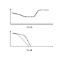
- FIG. 6A the velocity 601 of the first and second vehicles 201, 202 is plotted over time 602.
- the full line denotes the velocity of the second vehicle 202
- the dashed line denotes the velocity 601 of the first vehicle 201.
- the velocity 601 of the second vehicle 202 approximately equals the velocity of the first vehicle 201.
- the second vehicle 202 automatically follows the first vehicle 201 at a certain distance 300 (cf. FIG. 3 ).
- the distance 300 is set in dependence of a velocity of the second vehicle 202 and/or of a velocity of the first vehicle 201.
- the larger (smaller) velocity 600 the larger (smaller) the distance 300.
- the distance 300 can further depend on the dynamic response function 511.
- the distance 300 can be set to larger values. This allows to maintain a sufficient security distance when the second vehicle 202 follows the first vehicle 201.
- the dynamics response function 511 may be particularly relevant if the movement values solely include the driver movement request; in particular in such a case, the acceleration of the second vehicle 202 may be determined in dependence of the dynamics response function of the first vehicle 201.
- the dynamics response function may correlate a particular driver movement request with a future evolution of the movement values. In other words, based on the dynamics response function it may be possible to predict how the vehicle will react on a certain driver movement request. By such means it becomes possible to reliably follow the first vehicle 201.
- the acceleration of the second vehicle 202 can also be determined in dependence of the movement value 510 of the first vehicle 201.
- a more direct access to the movement values of the first vehicle 201 becomes possible.
- measurement errors or uncertainties in the measurement can be avoided; rather, a direct access to the movement values of the first vehicle 201 becomes possible.
- a change in the movement values of the first vehicle 201 may be anticipated based on the driver movement request and / or the dynamics response function.
- this may also increase the safety in driving.
- the second vehicle 202 can execute an emergency breaking.
- the negative acceleration of the first vehicle 201 (illustrated by the dashed line in FIG. 6B ) amounts to a comparably large value. Consequently, the deceleration of the second vehicle 202 is increased to a maximum level corresponding to the emergency breaking.
- step A2 it is determined whether the first and second vehicles 201, 202 are in immediate succession. Only if the first and second vehicles 201, 202 are in immediate succession, the method commences with step A3.
- step A3 the operational parameters 410, 510, 511 are wirelessly received from the first vehicle 201.
- the operational parameters can correspond to the image data 410 of the forward-view camera of the first vehicle 201 and/or to the movement values 510, 511 of the first vehicle.
Landscapes
- Physics & Mathematics (AREA)
- General Physics & Mathematics (AREA)
- Engineering & Computer Science (AREA)
- Chemical & Material Sciences (AREA)
- Combustion & Propulsion (AREA)
- Transportation (AREA)
- Mechanical Engineering (AREA)
- Traffic Control Systems (AREA)
Description
- Various embodiments relate to techniques of providing driver assistance for a driver of a vehicle. In particular, various techniques relate to receiving image data of a forward-view camera of a preceding vehicle and to receiving at least one movement value of the preceding vehicle.
- Techniques are known which enable to establish a wireless data connection between vehicles, e.g., passenger cars or trucks, located within a vicinity with respect to each other. For example, the wireless data connection can be according to the car-to-car (car2car) data communication standard. It is also known to exchange data between vehicles by means of the wireless local area network (WLAN) data communication standard.
- For example, it is known to exchange operational parameters between the vehicles via the wireless data connection. For example, applications of driver assistance can be realized which provide diver assistance and/or warning functionality, e.g. to all vehicles which are located within the vicinity. The vicinity may be defined in terms of a transmission range of the wireless data connection.
- However, such techniques may face certain restrictions. For example, sometimes it may be desirable to provide the driver assistance in a more selective manner than with respect to all vehicles within the vicinity.
- Accordingly, a need exists for advanced techniques of providing driver assistance which rely on wirelessly receiving at least one operational parameter of a further vehicle.
- This need is met by the features of the independent claims. The dependent claims define embodiments.
- According to an aspect, a method of providing driver assistance for a driver or a second vehicle by wirelessly receiving at least one operational parameter of a first vehicle is provided. The first vehicle is ahead of the second vehicle. The method comprises determining whether the first vehicle and the second vehicle move in immediate succession. The method further comprises, in dependence of the determining: the second vehicle selectively receiving the at least one operational parameter from the first vehicle. The method further comprises, based on the at least one operational parameter, providing the driver assistance.
- The first vehicle and the second vehicle moving in immediate succession may relate to the first vehicle driving directly ahead of the second vehicle. In other words, the first vehicle and the second vehicle moving in immediate succession may relate to no further vehicle being in between the first and second vehicles. For example, the first and second vehicles may drive on the same road and may drive in the same direction.
- The at least one operation parameter may be received via a wireless data connection established between the first and second vehicles. The wireless data connection may be according to the WLAN standard and / or according to the car2car standard. Other examples of the wireless data connection may include: Bluetooth, Near Field Communication, mobile telephony network, etc. For example, the method may further comprise: in response to the determining, selectively establishing the wireless data connection if the first and second vehicles move in immediate succession. E.g., for this establishing of the wireless data connection, position data of the first vehicle and/or the second vehicle may be exchanged between the first and second vehicles. The position data may be determined using a vehicle navigation system.
- In further scenarios, it may additionally or alternatively be possible that the second vehicle is configured to determine an identification number of the first vehicle from image data which is obtained from a forward-view camera of the second vehicle. For example, the identification number can at least partly correspond to a license plate number of the first vehicle which may be obtained, e.g., via image analysis of the obtained image data which images the license plate of the first vehicle. It is also possible that the identification number corresponds to a machine readable code which is obtained from markers and/or relates to a light pulse sequence emitted by a light source arranged on a read part of the first vehicle. Then the second vehicle may broadcast a wireless data connection request which at least partly includes the determined identification number of the first vehicle. The second vehicle may further receive a wireless data connection reply which may, e.g., be sent by the first vehicle in response to receiving the wireless data connection request. The wireless data connection reply may comprise at least parts of the identification number of the first vehicle, e.g., parts which had been missing in the wireless data connection request. Further, the wireless data connection reply may optionally comprise at least parts of an identification number of the second vehicle. Then, in response to the receiving of the wireless data connection reply, the second vehicle and / or the first vehicle may participate in the establishing of the wireless data connection between the first and second vehicles. In such scenarios, because it is typically only possible to determine the identification number of the first vehicle from the image data obtained from the forward-view camera of the second vehicle if the first vehicle is directly ahead of the second vehicle, it may be ensured that the wireless data connection is established only if the first and second vehicles move in immediate succession. In other words and generally, the determining whether the first vehicle and the second vehicle move in immediate succession may at least comprise optical verification of the movement in succession.
- As can be seen from the above, various techniques are conceivable which may be employed as part of the determining whether the first and second vehicles move in immediate succession. The above examples are not to be construed as being limiting.
- Various effects may be obtained by the techniques as described above. E.g., it may be possible to provide the driver assistance in a manner which makes use of the first vehicle being ahead of the second vehicle. In other words, the driver assistance may relate to an application which particularly relies on the scenario of the first and second vehicles moving in immediate succession. Moreover, it may be possible to reduce an amount of data traffic present on the wireless data connection. Namely, while in conventional scenarios the wireless data connection is typically established between all vehicles which are situated in the respective vicinity corresponding to, e.g., the transmission range, according to the presently discussed techniques the wireless data connection may be restricted to communication between the first and the second vehicles. Then a transmission power may be reduced, because typically the distance between the first and second vehicles may be comparably small; by this, frequency band resources which would be otherwise occupied may be released. Also resources in further vehicles which are not participating may be released.
- For example, the operational parameter may correspond to image data of a forward-view camera of the first vehicle. The providing of the driver assistance may include displaying at least parts of the image data on a display.
- By such means, it may be possible to provide the driver of the second vehicle with an expanded or enhanced viewing range. In particular, a driver of the second vehicle may see what is ahead of the first vehicle which, in turn, is driving ahead of the second vehicle. In such a manner, obstructions and/or dangerous situations on the road ahead of the first and second vehicles may be detected comparably early by the driver of the second vehicle. The safety in driving may increase. Obstacles on the road, which would be otherwise hidden, e.g., by curvature of the road and / or the first vehicle itself, may become visible to the driver of the second vehicle from the displaying of the at least parts of the image data on the display.
- The display may be a Liquid Crystal Display (LCD) fixedly installed in the second vehicle, a head up display, and / or a display of a portable device which may be connected with a vehicle head unit of the second vehicle, etc.
- For example, the image data of the forward-view camera of the first vehicle may be encoded as digital data. The image data may be compressed in order to reduce the amount of data to be transmitted via the wireless data connection. For example, the image data of the forward-view camera of the first vehicle received by the second vehicle may correspond to moving images, i.e., a movie. For example, a refresh rate of the image data which is received by the second vehicle may be less than a refresh rate of the image data being originally obtained by the forward-view camera of the first vehicle. By such means, an amount of data to be transmitted via the wireless data connection can be further reduced.
- For example, a comparably short amount of time may elapse between obtaining of the image data by the forward-view camera of the first vehicle and the displaying of the at least parts of the image data on the display of the second vehicle. For example, the short amount of time may relate to a substantially real-time playback, i.e., less than 1 second, or less than 0.5 seconds, or even shorter times.
- For example, the method may further comprise establishing whether a passing of the first vehicle by the second vehicle is desired. The displaying and/or the selectively receiving may further depend on the establishing whether the passing of the first vehicle by the second vehicle is desired.
- For example, if it is established that a high likelihood exists that the driver of the second vehicle intends to pass the first vehicle, the driver assistance may be provided in the form of the displaying of the at least parts of the image data on the display of the second vehicle. Then it may be possible for the driver of the second vehicle to base the decision whether to pass the first vehicle on the extended viewing range achieved via the displayed image data. For example, if oncoming traffic is visible in the image data, a warning may be additionally issued and the driver of the second vehicle may postpone the passing the first vehicle. All this may increase traffic safety.
- For example, the establishing whether the passing of the first vehicle by the second vehicle is desired can be based on user input, i.e., occur manually. However, it may also be possible that the establishing occurs automatically. For example, the establishing whether the passing of the first vehicle by the second vehicle is desired may be based on elements selected from the group comprising: a curviness of a road on which the second vehicle travels; a current velocity of the second vehicle; a historic velocity of the second vehicle; a distance between the second vehicle and the first vehicle; a distance to an upcoming curve on the road on which the second vehicle travels; traffic signs detected based on the image data of the forward-view camera of the first vehicle and/or based on further image data of a forward-view camera of the second vehicle; opposing traffic detected based on the image data of the forward-view camera of the first vehicle and / or based on the further image data of the forward-view camera of the second vehicle; lane markings of the road detected based on the image data of the forward-view camera of the first vehicle and/or based on the further image data of the forward-view camera of the second vehicle; and user input.
- Examples of decision criterions in view of the above-mentioned factors influencing the establishing are given below; however, these decision criterions are merely examples and are not to be construed as being limiting: E.g., if the curviness of the road on which the second vehicle travels is smaller (larger) than a threshold, it may be established that the passing of the first vehicle is (not) desired. E.g., if the current velocity of the second vehicle is equal or above (below) the historic velocity of the second vehicle, e.g., on the particular road type of the road on which the second vehicle travels, it may be established that the passing is (not) desired. A moving window may be employed for averaging when determining the historic velocity. E.g., if the distance between the second vehicle and the first vehicle is smaller (larger) than a threshold distance, it may be established that the passing of the first vehicle is (not) desired. E.g., if the traffic signs and/or the lane markings indicate a passing restriction, it may be established that the passing of the first vehicle is not desired. Likewise, if opposing traffic is detected, it may be established that the passing is not desired. For example, if various of the above-mentioned criteria are fulfilled, a human machine interface (HMI) may prompt the user whether he intends to pass the first vehicle which is driving ahead. Then, in response to the user input and/or various of the above-mentioned criteria being fulfilled, the driver assistance in form of the displaying of the image data may be provided.
- The above-mentioned techniques may have the effect that the driver assistance is provided in a selective manner. E.g., only if the passing of the first vehicle becomes comparably likely, i.e., if a likelihood exceeds a predefined threshold, the driver assistance in the form of the displaying of the image data may be provided. All this may reduce a workload imposed on the driver of the second vehicle. Further, traffic safety may be increased by not unnecessarily disturbing the driver of the second vehicle.
- The method may further comprise sending a message to the first vehicle which includes a warning indicating the passing of the first vehicle by the second vehicle. E.g., the message can be sent via the wireless data connection which is employed for the receiving of the at least one operational parameter. The message may also relate to the second vehicle operating front lights and / or a horn. By such means, if the passing of the first vehicle by the second vehicle is imminent, it becomes possible to warn the driver of the first vehicle in order to avoid dangerous situations.
- Above, techniques have been discussed predominantly which relate to the operational parameter corresponding to the image data of the forward-view camera of the first vehicle. The driver assistance may be provided in order to assist the driver of the second vehicle in passing of the first vehicle. Below, techniques will be discussed predominantly where the at least one operational parameter corresponds to at least one movement value of the first vehicle.
- E.g., the movement value of the first vehicle may correspond to a driver movement request and/or to a measured movement value. E.g., the driver movement request may relate to a braking pedal actuation and/or may relate to a throttle pedal actuation by the driver of the first vehicle. E.g., the measured movement value may be one of a current acceleration, a current velocity, and a current position of the first vehicle. Other movement values may be selected from the group comprising: revolution rate of a motor of the first vehicle, fuel level, cruise control engaged, headlights on/off, etc. In other words, the driver movement request may correspond to a user actuation which aims at setting of a certain movement value; likewise, the measured movement value may corresponds to the actual movement value as presently measured. For example, the movement value may include elements selected from the group comprising: a signal indicating an actuation of a brake pedal of the first vehicle; a signal indicating an actuation of a throttle pedal of the first vehicle; an indicator indicating a current velocity of the first vehicle; an indicator indicating a current change of velocity of the first vehicle; an indicator indicating a current position of the first vehicle.
- By such techniques it may be possible to directly access the movement characteristics of the first vehicle. Dangerous situations may be detected quickly and directly. Also it may be possible to correlate the movement characteristics of the first and second vehicle, e.g., it may be possible to maintain a minimum distance between the first and second vehicle or align acceleration and velocity of the first and second vehicles. In other words, a convoy driving of the first and second vehicles may be achieved. This may release the driver of the second vehicle from certain driving tasks.
- In particular, by the above-mentioned techniques it may be expendable to measure the movement value indirectly by sensor means of the second vehicle. For example, in various reference implementations it is known to provide the sensor means in the form of a radar, lidar, and / or an optical camera in the second vehicle. Here the movement values of the first vehicle may be measured by the sensors of the second vehicle. Such techniques typically show a significant inherent uncertainty due to limited measurement accuracy and may furthermore be subject to failure and errors. In contrast, by receiving the operational parameter in the form of the movement value of the first vehicle driving ahead of the second vehicle, a more direct and fail-safe way of obtaining information on the movement values of the first vehicle is achieved. E.g., the movement values may be received in digital format, e.g., including a checksum. By such means, errors of transmission may be reduced. Further, the measurement of the movement values of the first vehicle by sensors of the first vehicle may be more accurate and reliable due to a higher measurement accuracy than the measurement of the movement value of the first vehicle by sensors of the second vehicle.
- A further effect which may be achieved by the above-techniques, where the driver movement request is received, is described in the following: in various reference implementations where the movement value of the first vehicle is measured by sensors of the second vehicle, a current state of the motion of the first vehicle may be determined. When receiving the movement value in the form of the driver movement request, to a certain degree the state of motion of the first vehicle may be anticipated, i.e., predicted. This is because typically the motion state of the first vehicle will follow the driver movement request with a certain delay. E.g., if the driver actuates the throttle pedal, the vehicle will begin to accelerate with a certain inertia given by limited power resources. Only after a while a faster velocity is reached, i.e., the movement request is realized. Of course, it is typically not possible to measure the driver movement request of the driver of the first vehicle by sensors of the second vehicle.
- For example, the providing of the driver assistance may comprise the second vehicle automatically following the first vehicle at a distance based on the received at least one movement value of the first vehicle. For example, if the first vehicle accelerates, i.e., shows a decrease or increase of its velocity, this acceleration may be adapted by the second vehicle. This may relate to the convoy driving. In such a manner, the driver of the second vehicle may be released of certain driving tasks, thereby reducing the workload imposed on the driver of the second vehicle and increasing safety.
- In particular, in dangerous situations, e.g., where the first vehicle performs a strong braking, a reaction time of the driver of the second vehicle, which in conventional scenarios delays the onset of braking by the second vehicle, may be circumvented. The overall time needed to bring the second vehicle to a complete stop may be reduced.
- The automatically following may comprise: based on the received at least one movement value of the first vehicle, controlling a brake system of the second vehicle to decelerate the second vehicle and / or controlling a throttle system of the second vehicle to accelerate the second vehicle, thereby maintaining the distance.
- The providing of the driver assistance may further comprise setting the distance at least in dependence of a velocity of the second vehicle and / or of the first vehicle. E.g., for larger (smaller) velocities of the first vehicle and / or the second vehicle, a larger (smaller) distance may be set. This may ensure that breaking is possible in case of dangerous situations.
- The at least one operational parameter may comprise a dynamic response function of the first vehicle which characterizes elements of movement capabilities of the first vehicle. The setting of the distance may further depend on the received dynamics response function. For example, the dynamics response function may specify a maximum positive and/or negative acceleration, sometimes referred to as deceleration, of the first vehicle. For example, a sports car may typically have a dynamics response function which indicates a larger maximum positive acceleration than a family van. The dynamics response function may specify a maximum velocity of the first vehicle. For example, if the dynamics response function indicates a large (small) maximum negative acceleration of the first vehicle, the distance may be set to larger (smaller) values. The dynamics response function may alternatively or additionally correlate the driver movement request with a temporal evolution of the measured movement value. For example, if a certain velocity and throttle pedal actuation is received together with a corresponding dynamics response function, the amount of acceleration over the next seconds may be determined. Of course, in general it may be possible to anticipate the movement values over time even without the knowledge of the dynamics response function. As can be seen from the above, the type and information content of the dynamics response function is not particularly limited.
- It is also possible that the method further comprises determining the acceleration of the second vehicle in dependence of the dynamics response function of the first vehicle and in dependence of the movement value of the first vehicle. Optionally, the determining of the acceleration of the second vehicle may be in dependence of a dynamics response function of the second vehicle.
- For example, if the negative acceleration of the second vehicle as indicated by the at least one operational parameter received by the second vehicle equals a maximum negative acceleration as indicated by the dynamics response function of the first vehicle, it may be possible to determine the acceleration of the second vehicle such that the second vehicle executes an emergency braking. Typically, in such a situation the acceleration of the second vehicle may be determined as a maximum negative value.
- In general, it is possible to determine any movement value of the second vehicle in dependence of the dynamics response function of the first vehicle. Techniques as described above may be readily applied.
- Likewise, the providing of the driver assistance may include the second vehicle executing an emergency braking when a current acceleration of the first vehicle exceeds a threshold.
- According to a further aspect, a driver assistance entity of a second vehicle is provided. The driver assistance entity is configured for providing driver assistance for a driver of the second vehicle by wirelessly receiving at least one operational parameter of the first vehicle. The first vehicle is ahead of the second vehicle. The driver assistance entity comprises a processor which is configured to determine whether the first vehicle and the second vehicle move in immediate succession. The driver assistance entity further comprises a transceiver which is configured to selectively receive the at least one operational parameter from the first vehicle in dependence of the determining. The driver assistance entity is further configured to provide the driver assistance based on the at least one operational parameter.
- For example, the driver assistance entity according to the presently discussed aspect may be configured to execute the method of providing driver assistance according to a further aspect of the present application.
- For such a driver assistance entity, effects may be obtained which are comparable to the effects which may be obtained with the method of providing driver assistance according to a further aspect of the present application.
- Features mentioned above and features yet to be explained may not only be used in isolation or in combination as explicitly indicated, but also in other combinations. Features and embodiments of the present application may be combined unless explicitly mentioned otherwise.
- Various features of embodiments of the present application will become more apparent when read in conjunction with the accompanying drawings. In these drawings:
-
FIG. 1 is a schematic illustration of a driver assistance entity according to various embodiments. -
FIG. 2 shows a first vehicle driving ahead of a second vehicle with a wireless data connection being established between the first and second vehicles. -
FIG. 3 shows fields of views of the first vehicle and the second vehicle. -
FIG. 4 illustrates the displaying of image data obtained with a forward-view camera of the first vehicle on a display of the second vehicle. -
FIG. 5A shows movement values of the first vehicle. -
Fig. 5B sows a dynamics response function of the first vehicle. -
FIG. 6A illustrates a velocity of the first and second vehicles over time when the second vehicle follows the first vehicle. -
FIG. 6B illustrates the velocity of the first and second vehicles when the second vehicle executes an emergency braking. -
FIG. 7 is a flowchart of a method of providing driver assistance according to various embodiments. - In the following, embodiments of the invention will be described in detail with reference to the accompanying drawings. It is to be understood that the following description of the embodiments is not to be taken in a limiting sense. The scope of the invention is not intended to be limited by the embodiments described hereinafter or by the drawings, which are to be taken demonstrative only.
- The drawings are to be regarded as being schematic representations and elements illustrated in the drawings are not necessarily shown to scale. Rather, the various elements are represented such that their function and general purpose become apparent for a person skilled in the art. Any connection or coupling between functional blocks, devices, components or other physical or functional units shown in the drawings or described herein may also be implemented by an indirect connection or coupling. A coupling between components may also be established over a wireless connection, unless noted otherwise. Functional blocks may be implemented in hardware, firmware, software, or a combination thereof.
- Hereinafter, techniques are described which enable to provide driver assistance to a driver of a second vehicle if the second vehicle drives directly behind a first vehicle. In other words, if it is determined that the first vehicle and the second vehicle move in immediate succession, the driver assistance is provided. In particular, the driver assistance relies on at least one operational parameter of the first vehicle which is wirelessly received by the second vehicle. For example, the operational parameter may correspond to image data of a forward-view camera of the first vehicle and/or may correspond to a movement value of the first vehicle. Based on such operational parameters it is possible to provide the driver assistance such that it makes use of the first vehicle and the second vehicle moving in immediate succession.
- In
FIG. 1 , adriver assistance entity 100 which is configured to execute techniques as mentioned above is illustrated. A respectivedriver assistance entity 100 may be part of the first vehicle and / or of the first vehicle. Thedriver assistance entities 100 of the first and the second vehicles may be inter-related and provide corresponding functionality. Thedriver assistance entity 100 comprises aprocessor 111 which can access amemory 114. Theprocessor 111 is configured to execute various tasks, which can be selected from the group comprising: image data analysis of image data received via atransceiver 113; providing the driver assistance; controlling vehicle components as part of the providing of the driver assistance; receiving input from a user of thedriver assistance entity 100 via ahuman machine interface 115; outputting information to the user via thehuman machine interface 115; obtaining and analyzing image data which is acquired with a forward-view camera 120 and received via adata interface 112; etc. For example, theprocessor 111 can be a single core processor or a multi core processor. Various functionalities of theprocessor 111, e.g., as mentioned above, may be implemented as software which is executed by different physical entities. In other words, it is not necessary that theprocessor 111 is implemented as a single physical entity; rather, the various functions of theprocessor 111 may be realized by a plurality of various physical entities. Furthermore, functionality of theprocessor 111 will become apparent from the detailed description of the techniques hereinafter. - The
HMI 115 can comprise a display. Thetransceiver 113 may operate according to the car2car communication standard and / or the WLAN standard. It can establish a wireless data connection between vehicles. Thememory 114 can be a permanent memory. Thecamera 120 can be an optical camera and / or provide sensitivity in the infrared region of the spectrum. Thedriver assistance entity 100 can be further coupled with a navigation device which has access to a map database including a network of road segments. E.g., from such data a curviness of the road and / or a distance to an upcoming curve and / or speed limits and / or passing restrictions, etc. can be determined. - Turning to
FIG. 2 , a situation of afirst vehicle 201 and asecond vehicle 202 driving in immediate succession, wherein thefirst vehicle 201 moves ahead of thesecond vehicle 202, is illustrated. Thewireless data connection 230 is established between the first andsecond vehicles second vehicles transmission range 211 of thewireless data connection 230 is illustrated. As can be seen,further vehicles 203 are situated within thetransmission range 211. Thefurther vehicles 203 do not participate in thewireless data connection 230. - Before establishing the
wireless data connection 230 between the first andsecond vehicles second vehicles first vehicle 201 is ahead of thesecond vehicle 202, e.g, by analyzing the image data acquired with the forward-view camera 120 of thedriver assistance entity 100 of thesecond vehicle 202. InFIG. 2 , theviewing range 210 of the forward-view camera 120 of thesecond vehicle 202 is indicated. As can be seen, theviewing range 210 covers a rear portion of thefirst vehicle 201. E.g., due to this it can be established that thefirst vehicle 201 drives immediately ahead. This may further include verifying that a license plate number of a license plate mounted on the rearward portion of thefirst vehicle 201 matches the identification number of thefirst vehicle 201 transmitted via thewireless data connection 230. Various alternative techniques are possible in order to establish that the first and thesecond vehicles - Once it is determined that the first and
second vehicles second vehicle 202 selectively receives at least one operational parameter from thefirst vehicle 201 via thewireless data connection 230. Based on this received at least one operational parameter, driver assistance is provided to the driver of thesecond vehicle 202. - E.g., the at least one operational parameter can correspond to image data of a forward-view camera of the
first vehicle 201. InFIG. 3 , the fields ofview 210 of forward-view cameras (not shown inFIG. 3 ) of the first and thesecond vehicles second vehicles FIG. 3 , the field ofview 210 of thefirst vehicle 201 covers a part of the road ahead of thesecond vehicle 202 which is not covered by the field ofview 210 of the forward-view camera of thesecond vehicle 202. Further, areas ahead of thefirst vehicle 201 are obstructed in the direct line of sight of the driver of thesecond vehicle 202, but are visible in the image data. Thereby, by displaying image data of the forward-view camera of thefirst vehicle 201 on the display of thesecond vehicle 202, it may be possible that the driver of thesecond vehicle 202 obtains a better overview of the situation on the road ahead. For example, the display on which the image data of the forward-view camera of thefirst vehicle 201 is displayed may be part of theHMI 115 of thedriver assistance entity 100 of the second vehicle 202 (cf.FIG. 1 ). For example, the display of theHMI 115 may be fixedly installed in thesecond vehicle 202 and/or may be a display of a portable user equipment. - In
FIG. 4 , thedisplay 401 of thedriver assistance entity 100 of thesecond vehicle 202 is schematically illustrated. As can be seen fromFIG. 4 , parts of theimage data 410 of the forward-view camera of thefirst vehicle 201 are displayed on thedisplay 401. Opposing traffic can be seen on the road. In such a situation, it may be established that a passing of thefirst vehicle 201 by thesecond vehicle 202 is undesirable due to the opposing traffic. Further criteria may be used in order to establish whether the passing of thefirst vehicle 201 by thesecond vehicle 202 is desired. For example, a curviness of the road on which thesecond vehicle 202 travels may be determined, and based on the curviness it may be established whether the passing is desired. The curviness may be determined from the map data of the navigation system of thesecond vehicle 202. For example, in the scenario ofFIG. 3 , a large curviness of the road on which thesecond vehicle 202 travels is present. In such a scenario, it may be undesirable to pass thefirst vehicle 201. Further criteria based on which it can be established whether the passing of thefirst vehicle 201 is desired can be selected from the group comprising: a current velocity of thesecond vehicle 202; a historic velocity of thesecond vehicle 202; a distance between thesecond vehicle 202 and thefirst vehicle 201; a distance to an upcoming curve on a road on which thesecond vehicle 202 travels; traffic signs detected based on theimage data 410 of the forward-view camera of thefirst vehicle 201 and/or further image data of the forward-view camera 120 of thesecond vehicle 202; passing restrictions; lane markings of the road on which thesecond vehicle 202 travels, the lane markings being detected based on theimage data 410 and/or on further image data of the forward-view camera 120 of thesecond vehicle 202. Alternatively or additionally, a user input obtained via theHMI 115 may be used in order to determine whether it is desired to pass thefirst vehicle 201. E.g., the user input may correspond to an actuation of a throttle pedal or may correspond to the operation of a left blinker. The user input may also relate to a voice command, a gesture, pushing of a button, etc. - E.g., once it is determined that the passing of the
first vehicle 201 is desired, it is possible to send a message to thefirst vehicle 201 via thewireless data connection 230 which includes a warning. For example, by means of this message the driver of thefirst vehicle 201 can be made aware of the upcoming passing of thesecond vehicle 202. The warning may be issued to the driver of thefirst vehicle 201, e.g., by displaying of a corresponding message, or by issuing a voice instruction. - Above, scenarios have been predominantly discussed which relate to the driver assistance assisting the driver of the
second vehicle 202 in the passing of thefirst vehicle 201 driving ahead of thesecond vehicle 202. As will be appreciated, such a driver assistance application makes inherent use of the first andsecond vehicles second vehicle - Shown in
FIG. 5A is a scenario where the at least one operational parameter wirelessly received from thefirst vehicle 201 corresponds to movement values 510 of thefirst vehicle 201. The movement values 510 of thefirst vehicle 201 include a current velocity of thefirst vehicle 201, a current acceleration, a current gear, and a current revolution rate of the gear. Of course, it is possible to include other movement values or only parts of the movement values as indicated inFIG. 5A . E.g., the movement values as mentioned above can be directly measured by appropriate sensors in thefirst vehicle 201. - Alternatively or additionally it is also possible that the movement values 510 include a driver movement request (not shown in
Fig. 5A ), e.g., a braking pedal actuation and/or a throttle pedal actuation which are specified qualitatively and / or quantitatively. Typically, the measured movement values will - with a certain delay - conform to this driver movement request. Therefore, by considering the driver movement request it is possible to anticipate the future development of the measured movement values to a certain degree, e.g., for a couple of seconds or even longer periods of time. - In
FIG. 5B , the movement value in the form of thedynamics response function 511 of thefirst vehicle 201 is illustrated. Thedynamics response function 511 characterizes capabilities and general parameters of the movement of thefirst vehicle 201. In the scenario ofFIG. 5B , these parameters are maximum negative acceleration and maximum positive acceleration. For example, thedynamics response function 511 could further comprise a breaking distance, a remaining amount of fuel, a maximum velocity of thefirst vehicle 201, etc. The dynamics response function of thefirst vehicle 201 may be additionally or alternatively employed by thesecond vehicle 202 to translate a driver movement request into an estimated future movement value of thefirst vehicle 201, e.g., correlate a certain degree of throttle pedal actuation with a certain value of positive acceleration, etc.. - In general, it is possible that at least some movement values of the
second vehicle 202 are determined based on the receivedmovement value first vehicle 201. Such a situation is illustrated inFIG. 6A . InFIG. 6A , the velocity 601 of the first andsecond vehicles FIG. 6A , the full line denotes the velocity of thesecond vehicle 202 and the dashed line denotes the velocity 601 of thefirst vehicle 201. As can be seen, the velocity 601 of thesecond vehicle 202 approximately equals the velocity of thefirst vehicle 201. Namely, by controlling a breaking system and/or a throttle system of thesecond vehicle 202 in dependence of the receivedmovement values first vehicle 201, it becomes possible that thesecond vehicle 202 automatically follows thefirst vehicle 201 at a certain distance 300 (cf.FIG. 3 ). For example, it is possible that thedistance 300 is set in dependence of a velocity of thesecond vehicle 202 and/or of a velocity of thefirst vehicle 201. In a simple scenario, the larger (smaller) velocity 600, the larger (smaller) thedistance 300. For example, thedistance 300 can further depend on thedynamic response function 511. For example, if thedynamic response function 511 of thefirst vehicle 201 indicates a comparably large maximum negative acceleration of thefirst vehicle 201, thedistance 300 can be set to larger values. This allows to maintain a sufficient security distance when thesecond vehicle 202 follows thefirst vehicle 201. - Moreover, the
dynamics response function 511 may be particularly relevant if the movement values solely include the driver movement request; in particular in such a case, the acceleration of thesecond vehicle 202 may be determined in dependence of the dynamics response function of thefirst vehicle 201. In general, the dynamics response function may correlate a particular driver movement request with a future evolution of the movement values. In other words, based on the dynamics response function it may be possible to predict how the vehicle will react on a certain driver movement request. By such means it becomes possible to reliably follow thefirst vehicle 201. In general, the acceleration of thesecond vehicle 202 can also be determined in dependence of themovement value 510 of thefirst vehicle 201. - If compared to conventional scenarios where respective sensors of the
second vehicle 202 measure one or more movement values 510 of thefirst vehicle 201, a more direct access to the movement values of thefirst vehicle 201 becomes possible. In particular, measurement errors or uncertainties in the measurement can be avoided; rather, a direct access to the movement values of thefirst vehicle 201 becomes possible. Also, a change in the movement values of thefirst vehicle 201 may be anticipated based on the driver movement request and / or the dynamics response function. - Besides an increased comfort in driving due to the automatically following of the
first vehicle 201, this may also increase the safety in driving. For example, as illustrated inFIG. 6B , when an acceleration of the first vehicle falls below a threshold, thesecond vehicle 202 can execute an emergency breaking. As can be seen fromFIG. 6B , the negative acceleration of the first vehicle 201 (illustrated by the dashed line inFIG. 6B ) amounts to a comparably large value. Consequently, the deceleration of thesecond vehicle 202 is increased to a maximum level corresponding to the emergency breaking. - In
FIG. 7 , a flowchart of a method of providing driver assistance is illustrated. The method starts in step A1. In step A2 it is determined whether the first andsecond vehicles second vehicles operational parameters first vehicle 201. For example, the operational parameters can correspond to theimage data 410 of the forward-view camera of thefirst vehicle 201 and/or to the movement values 510, 511 of the first vehicle. - In step A4, the driver assistance is provided based on the received operational parameters of step A3. The method ends in step A5.
- Although the invention has been described with respect to certain preferred embodiments, various modifications will occur to the person skilled in the art. The invention is only limited by the scope of the appended claims.
Claims (15)
- A method of providing driver assistance for a driver of a second vehicle (202) by wirelessly receiving at least one operational parameter (410, 510, 511) of a first vehicle (201), the first vehicle (201) being ahead of the second vehicle (202), the method comprising:- determining whether the first vehicle (201) and the second vehicle (202) move in immediate succession,- in dependence of the determining, the second vehicle (202) selectively receiving the at least one operational parameter (410, 510, 511) from the first vehicle (201),- based on the at least one operational parameter (410, 510, 511), providing the driver assistance.
- The method of claim 1,
wherein the at least one operational parameter (410, 510, 511) corresponds to image data (410) of a forward-view camera of the first vehicle (201),
wherein the providing of the driver assistance includes displaying at least parts of the image data (410) on a display (401). - The method of claim 2, further comprising:- establishing whether the passing of the first vehicle (201) by the second vehicle (202) is desired, wherein the displaying and / or the selectively receiving further depends on the establishing.
- The method of claim 3,
wherein the establishing whether the passing of the first vehicle (201) by the second vehicle (202) is desired is based on elements selected from the group comprising:- a curviness of a road on which the second vehicle (202) travels;- a current velocity (600) of the second vehicle (202);- a historic velocity of the second vehicle (202);- a distance (300) between the second vehicle (202) and the first vehicle (201);- a distance to an upcoming curve on the road on which the second vehicle (202) travels;- traffic signs detected based on the image data (410) of the forward-view camera of the first vehicle (201) and / or further image data of a forward-view camera of the second vehicle (202);- opposing traffic detected based on the image data (410) of the forward-view camera of the first vehicle (201);- lane markings of the road detected based on the image data (410) of the forward-view camera of the first vehicle (201) and / or based on the further image data of the second vehicle (202); and- a user input. - The method of any one of the claims 2 - 4, further comprising:- sending a message to the first vehicle (201), the message including a warning indicating the passing of the first vehicle (201) by the second vehicle (202).
- The method of claim 1,
wherein the at least one operational parameter (410, 510, 511) corresponds to at least one movement value (510, 511) of the first vehicle (201). - The method of claim 6,
wherein the movement value (510, 511) of the first vehicle (201) corresponds to a driver movement request and / or to a measured movement value. - The method of any one of claims 6 or 7,
wherein the providing of the driver assistance comprises:- the second vehicle (202) automatically following the first vehicle (201) at a distance (300) based on the received at least one movement value (510, 511) of the first vehicle (201). - The method of claim 8,
wherein the providing of the driver assistance further comprises:- setting the distance (300) at least in dependence of a velocity (600) of the second vehicle (202) and / or of the first vehicle (201). - The method of claim 9,
wherein the at least one operational parameter (510, 511) comprises a dynamics response function (511) of the first vehicle (201) which characterizes elements of movement capabilities of the first vehicle (201),
wherein the setting of the distance (300) further depends on the received dynamics response function. - The method of any one of claims 8 - 10,
wherein the at least one operational parameter (510, 511) comprises a dynamics response function (511) of the first vehicle (201) which characterizes elements of the dynamic movement of the first vehicle (201), the method further comprising:- determining the acceleration of the second vehicle (202) in dependence of the dynamics response function of the first vehicle (201) and / or the movement value (510, 511) of the first vehicle (201). - The method of any one of claims 6 - 11,
wherein the providing of the driver assistance includes the second vehicle (202) executing an emergency braking when a current deceleration of the first vehicle (201) exceeds a threshold. - The method of any one of the preceding claims,
wherein the determining whether the first vehicle (201) and the second vehicle (202) move in immediate succession at least comprises optical verification of the movement in succession. - Driver assistance entity (100) of a second vehicle (202) and which is configured for providing driver assistance for a driver of the second vehicle (202) by wirelessly receiving at least one operational parameter (410, 510, 511) of a first vehicle (201), the first vehicle (201) being ahead of the second vehicle (202), the driver assistance entity comprising:- a processor (111) configured to determine whether the first vehicle (201) and the second vehicle (202) move in immediate succession,- a transceiver (113) configured to selectively receive the at least one operational parameter (410, 510, 511) from the first vehicle (201) in dependence of the determining, the driver assistance entity (100) being configured to provide the driver assistance based on the at least one operational parameter (410, 510, 511).
- The driver assistance entity (100) of claim 14,
wherein the driver assistance entity (100) is further configured to execute a method according to any one of the claims 1 - 13.
Priority Applications (1)
| Application Number | Priority Date | Filing Date | Title |
|---|---|---|---|
| EP13176508.3A EP2827316B1 (en) | 2013-07-15 | 2013-07-15 | Driver assistance |
Applications Claiming Priority (1)
| Application Number | Priority Date | Filing Date | Title |
|---|---|---|---|
| EP13176508.3A EP2827316B1 (en) | 2013-07-15 | 2013-07-15 | Driver assistance |
Publications (2)
| Publication Number | Publication Date |
|---|---|
| EP2827316A1 true EP2827316A1 (en) | 2015-01-21 |
| EP2827316B1 EP2827316B1 (en) | 2020-02-12 |
Family
ID=48793039
Family Applications (1)
| Application Number | Title | Priority Date | Filing Date |
|---|---|---|---|
| EP13176508.3A Active EP2827316B1 (en) | 2013-07-15 | 2013-07-15 | Driver assistance |
Country Status (1)
| Country | Link |
|---|---|
| EP (1) | EP2827316B1 (en) |
Cited By (9)
| Publication number | Priority date | Publication date | Assignee | Title |
|---|---|---|---|---|
| CN104802704A (en) * | 2015-05-22 | 2015-07-29 | 武汉理工大学 | Automobile curve anti-collision pre-warning system based on mountainous road |
| DE102015202028A1 (en) * | 2015-02-05 | 2016-08-11 | Conti Temic Microelectronic Gmbh | Apparatus and method for detecting an existence of a car-to-car radio connection |
| US9632507B1 (en) | 2016-01-29 | 2017-04-25 | Meritor Wabco Vehicle Control Systems | System and method for adjusting vehicle platoon distances based on predicted external perturbations |
| WO2017125234A1 (en) * | 2016-01-23 | 2017-07-27 | Audi Ag | Method for operating a driver assistance system which is designed to carry out decelerating longitudinal guidance interventions as a function of traffic situation information describing the current traffic situation, and motor vehicle |
| CN107554517A (en) * | 2016-06-30 | 2018-01-09 | 比亚迪股份有限公司 | Control method for vehicle, device, vehicle and long-range Ride Control System |
| US10032318B1 (en) | 2016-04-15 | 2018-07-24 | Allstate Insurance Company | Crowd-sourced driver grading |
| FR3082091A1 (en) * | 2018-07-06 | 2019-12-06 | Orange | DRIVING AID TECHNIQUE |
| WO2020001941A1 (en) * | 2018-06-28 | 2020-01-02 | Zf Friedrichshafen Ag | Device and method for adapting a driving property of an ego-vehicle for driving around a curve |
| CN117218619A (en) * | 2023-11-07 | 2023-12-12 | 安徽中科星驰自动驾驶技术有限公司 | Lane recognition method and system for automatic driving vehicle |
Families Citing this family (1)
| Publication number | Priority date | Publication date | Assignee | Title |
|---|---|---|---|---|
| GB2609674A (en) * | 2021-08-12 | 2023-02-15 | Continental Automotive Gmbh | Method and vehicles for cooperative operation at an intersection |
Citations (10)
| Publication number | Priority date | Publication date | Assignee | Title |
|---|---|---|---|---|
| FR2790858A1 (en) * | 1999-03-11 | 2000-09-15 | Marc Bernasse | Detection system, for indicating to drivers approach or presence of motor cycles or emergency vehicles, includes emitter on motor cycle and emergency vehicle and receivers on other vehicle |
| DE102006016807A1 (en) * | 2006-04-10 | 2007-10-11 | Robert Bosch Gmbh | Method for improving view of drivers of motor vehicles entails vehicle travelling ahead producing image data by video camera, wherein evaluating unit effects transmission of image data to receiver on following vehicle |
| US20100123778A1 (en) * | 2008-11-14 | 2010-05-20 | Toyota Motor Engineering & Manufacturing North America, Inc. | Integrated Visual Display System |
| US20110032118A1 (en) * | 2008-04-07 | 2011-02-10 | Janus Interface Ltd. | Vehicle Awareness System |
| US20120095641A1 (en) * | 2006-11-23 | 2012-04-19 | Continental Automotive Gmbh | Method for Wireless Communication Between Vehicles |
| GB2485843A (en) * | 2010-11-29 | 2012-05-30 | Constantin Mosteanu | Apparatus to alert vehicle driver that a bicycle is approaching from behind |
| US20130041567A1 (en) * | 2011-08-10 | 2013-02-14 | Denso Corporation | Travel support apparatus and travel support system |
| US20130116861A1 (en) * | 2010-07-27 | 2013-05-09 | Toyota Jidosha Kabushiki Kaisha | Vehicle control system |
| US20130131949A1 (en) * | 2010-08-11 | 2013-05-23 | Toyota Jidosha Kabushiki Kaisha | Control device and control method for vehicle |
| US20130158852A1 (en) * | 2010-06-23 | 2013-06-20 | Continental Teve Ag & Co O.Hg | Method and System for Accelerated Object Recognition and/or Accelerated Object Attribute Recognition and Use of Said Method |
Family Cites Families (1)
| Publication number | Priority date | Publication date | Assignee | Title |
|---|---|---|---|---|
| DE102011009106A1 (en) * | 2011-01-21 | 2012-07-26 | Audi Ag | Method for operating a driver assistance system of a motor vehicle and motor vehicle issuing a recommendation relating to a passing process |
-
2013
- 2013-07-15 EP EP13176508.3A patent/EP2827316B1/en active Active
Patent Citations (10)
| Publication number | Priority date | Publication date | Assignee | Title |
|---|---|---|---|---|
| FR2790858A1 (en) * | 1999-03-11 | 2000-09-15 | Marc Bernasse | Detection system, for indicating to drivers approach or presence of motor cycles or emergency vehicles, includes emitter on motor cycle and emergency vehicle and receivers on other vehicle |
| DE102006016807A1 (en) * | 2006-04-10 | 2007-10-11 | Robert Bosch Gmbh | Method for improving view of drivers of motor vehicles entails vehicle travelling ahead producing image data by video camera, wherein evaluating unit effects transmission of image data to receiver on following vehicle |
| US20120095641A1 (en) * | 2006-11-23 | 2012-04-19 | Continental Automotive Gmbh | Method for Wireless Communication Between Vehicles |
| US20110032118A1 (en) * | 2008-04-07 | 2011-02-10 | Janus Interface Ltd. | Vehicle Awareness System |
| US20100123778A1 (en) * | 2008-11-14 | 2010-05-20 | Toyota Motor Engineering & Manufacturing North America, Inc. | Integrated Visual Display System |
| US20130158852A1 (en) * | 2010-06-23 | 2013-06-20 | Continental Teve Ag & Co O.Hg | Method and System for Accelerated Object Recognition and/or Accelerated Object Attribute Recognition and Use of Said Method |
| US20130116861A1 (en) * | 2010-07-27 | 2013-05-09 | Toyota Jidosha Kabushiki Kaisha | Vehicle control system |
| US20130131949A1 (en) * | 2010-08-11 | 2013-05-23 | Toyota Jidosha Kabushiki Kaisha | Control device and control method for vehicle |
| GB2485843A (en) * | 2010-11-29 | 2012-05-30 | Constantin Mosteanu | Apparatus to alert vehicle driver that a bicycle is approaching from behind |
| US20130041567A1 (en) * | 2011-08-10 | 2013-02-14 | Denso Corporation | Travel support apparatus and travel support system |
Cited By (13)
| Publication number | Priority date | Publication date | Assignee | Title |
|---|---|---|---|---|
| DE102015202028A1 (en) * | 2015-02-05 | 2016-08-11 | Conti Temic Microelectronic Gmbh | Apparatus and method for detecting an existence of a car-to-car radio connection |
| CN104802704A (en) * | 2015-05-22 | 2015-07-29 | 武汉理工大学 | Automobile curve anti-collision pre-warning system based on mountainous road |
| WO2017125234A1 (en) * | 2016-01-23 | 2017-07-27 | Audi Ag | Method for operating a driver assistance system which is designed to carry out decelerating longitudinal guidance interventions as a function of traffic situation information describing the current traffic situation, and motor vehicle |
| US9632507B1 (en) | 2016-01-29 | 2017-04-25 | Meritor Wabco Vehicle Control Systems | System and method for adjusting vehicle platoon distances based on predicted external perturbations |
| US10360738B1 (en) | 2016-04-15 | 2019-07-23 | Allstate Insurance Company | Crowd-sourced driver grading |
| US10032318B1 (en) | 2016-04-15 | 2018-07-24 | Allstate Insurance Company | Crowd-sourced driver grading |
| US10504304B1 (en) | 2016-04-15 | 2019-12-10 | Allstate Insurance Company | Crowd-sourced driver grading |
| US10891808B1 (en) | 2016-04-15 | 2021-01-12 | Allstate Insurance Company | Crowd-sourced driver grading |
| US11688209B1 (en) | 2016-04-15 | 2023-06-27 | Allstate Insurance Company | Crowd-sourced driver grading |
| CN107554517A (en) * | 2016-06-30 | 2018-01-09 | 比亚迪股份有限公司 | Control method for vehicle, device, vehicle and long-range Ride Control System |
| WO2020001941A1 (en) * | 2018-06-28 | 2020-01-02 | Zf Friedrichshafen Ag | Device and method for adapting a driving property of an ego-vehicle for driving around a curve |
| FR3082091A1 (en) * | 2018-07-06 | 2019-12-06 | Orange | DRIVING AID TECHNIQUE |
| CN117218619A (en) * | 2023-11-07 | 2023-12-12 | 安徽中科星驰自动驾驶技术有限公司 | Lane recognition method and system for automatic driving vehicle |
Also Published As
| Publication number | Publication date |
|---|---|
| EP2827316B1 (en) | 2020-02-12 |
Similar Documents
| Publication | Publication Date | Title |
|---|---|---|
| EP2827316B1 (en) | Driver assistance | |
| US11069245B2 (en) | Lane change timing indicator | |
| US10068480B2 (en) | Driving support apparatus | |
| CN112771592B (en) | Method for warning a driver of a motor vehicle, control device and motor vehicle | |
| EP3936394B1 (en) | Vehicle control device, vehicle control method, and program | |
| JP6112054B2 (en) | Electronic device, electronic device control method, and electronic device control program | |
| US10137907B2 (en) | Startup suggestion device and startup suggestion method | |
| CN102265317B (en) | driving aids | |
| US20190004513A1 (en) | Driving assistance control apparatus | |
| CN108122432A (en) | For asking for the method for the data of traffic | |
| US12151677B2 (en) | Vehicle control device, vehicle control method, program, and vehicle | |
| CN110446645B (en) | Vehicle control device | |
| JP4983564B2 (en) | Vehicle tracking device | |
| JP5423158B2 (en) | Brake control device | |
| JP2009140327A (en) | Driving support device | |
| JP5310276B2 (en) | Driving assistance device | |
| WO2022230781A1 (en) | Vehicular notification control device, and vehicular notification control method | |
| US11840175B2 (en) | Traffic signal alarm device having no navigational control | |
| CN115649190A (en) | Control method, device, medium, vehicle and chip for vehicle auxiliary braking | |
| US12311837B2 (en) | Vehicle notification control device and vehicle notification control method | |
| JP7516445B2 (en) | Driving Support Devices | |
| JP6668678B2 (en) | Driving support device | |
| JP2011103078A (en) | Drive support device | |
| CN114694396A (en) | Method, apparatus, electronic device, vehicle, and medium for controlling vehicle | |
| JP2017004339A (en) | Driver support device for vehicle |
Legal Events
| Date | Code | Title | Description |
|---|---|---|---|
| 17P | Request for examination filed |
Effective date: 20130715 |
|
| AK | Designated contracting states |
Kind code of ref document: A1 Designated state(s): AL AT BE BG CH CY CZ DE DK EE ES FI FR GB GR HR HU IE IS IT LI LT LU LV MC MK MT NL NO PL PT RO RS SE SI SK SM TR |
|
| AX | Request for extension of the european patent |
Extension state: BA ME |
|
| PUAI | Public reference made under article 153(3) epc to a published international application that has entered the european phase |
Free format text: ORIGINAL CODE: 0009012 |
|
| R17P | Request for examination filed (corrected) |
Effective date: 20150709 |
|
| RBV | Designated contracting states (corrected) |
Designated state(s): AL AT BE BG CH CY CZ DE DK EE ES FI FR GB GR HR HU IE IS IT LI LT LU LV MC MK MT NL NO PL PT RO RS SE SI SK SM TR |
|
| STAA | Information on the status of an ep patent application or granted ep patent |
Free format text: STATUS: EXAMINATION IS IN PROGRESS |
|
| 17Q | First examination report despatched |
Effective date: 20180625 |
|
| GRAP | Despatch of communication of intention to grant a patent |
Free format text: ORIGINAL CODE: EPIDOSNIGR1 |
|
| STAA | Information on the status of an ep patent application or granted ep patent |
Free format text: STATUS: GRANT OF PATENT IS INTENDED |
|
| INTG | Intention to grant announced |
Effective date: 20191017 |
|
| GRAS | Grant fee paid |
Free format text: ORIGINAL CODE: EPIDOSNIGR3 |
|
| GRAA | (expected) grant |
Free format text: ORIGINAL CODE: 0009210 |
|
| STAA | Information on the status of an ep patent application or granted ep patent |
Free format text: STATUS: THE PATENT HAS BEEN GRANTED |
|
| AK | Designated contracting states |
Kind code of ref document: B1 Designated state(s): AL AT BE BG CH CY CZ DE DK EE ES FI FR GB GR HR HU IE IS IT LI LT LU LV MC MK MT NL NO PL PT RO RS SE SI SK SM TR |
|
| REG | Reference to a national code |
Ref country code: GB Ref legal event code: FG4D |
|
| REG | Reference to a national code |
Ref country code: CH Ref legal event code: EP |
|
| REG | Reference to a national code |
Ref country code: AT Ref legal event code: REF Ref document number: 1233150 Country of ref document: AT Kind code of ref document: T Effective date: 20200215 |
|
| REG | Reference to a national code |
Ref country code: DE Ref legal event code: R096 Ref document number: 602013065625 Country of ref document: DE |
|
| REG | Reference to a national code |
Ref country code: IE Ref legal event code: FG4D |
|
| PG25 | Lapsed in a contracting state [announced via postgrant information from national office to epo] |
Ref country code: RS Free format text: LAPSE BECAUSE OF FAILURE TO SUBMIT A TRANSLATION OF THE DESCRIPTION OR TO PAY THE FEE WITHIN THE PRESCRIBED TIME-LIMIT Effective date: 20200212 Ref country code: FI Free format text: LAPSE BECAUSE OF FAILURE TO SUBMIT A TRANSLATION OF THE DESCRIPTION OR TO PAY THE FEE WITHIN THE PRESCRIBED TIME-LIMIT Effective date: 20200212 Ref country code: NO Free format text: LAPSE BECAUSE OF FAILURE TO SUBMIT A TRANSLATION OF THE DESCRIPTION OR TO PAY THE FEE WITHIN THE PRESCRIBED TIME-LIMIT Effective date: 20200512 |
|
| REG | Reference to a national code |
Ref country code: LT Ref legal event code: MG4D |
|
| REG | Reference to a national code |
Ref country code: NL Ref legal event code: MP Effective date: 20200212 |
|
| PG25 | Lapsed in a contracting state [announced via postgrant information from national office to epo] |
Ref country code: HR Free format text: LAPSE BECAUSE OF FAILURE TO SUBMIT A TRANSLATION OF THE DESCRIPTION OR TO PAY THE FEE WITHIN THE PRESCRIBED TIME-LIMIT Effective date: 20200212 Ref country code: GR Free format text: LAPSE BECAUSE OF FAILURE TO SUBMIT A TRANSLATION OF THE DESCRIPTION OR TO PAY THE FEE WITHIN THE PRESCRIBED TIME-LIMIT Effective date: 20200513 Ref country code: BG Free format text: LAPSE BECAUSE OF FAILURE TO SUBMIT A TRANSLATION OF THE DESCRIPTION OR TO PAY THE FEE WITHIN THE PRESCRIBED TIME-LIMIT Effective date: 20200512 Ref country code: SE Free format text: LAPSE BECAUSE OF FAILURE TO SUBMIT A TRANSLATION OF THE DESCRIPTION OR TO PAY THE FEE WITHIN THE PRESCRIBED TIME-LIMIT Effective date: 20200212 Ref country code: LV Free format text: LAPSE BECAUSE OF FAILURE TO SUBMIT A TRANSLATION OF THE DESCRIPTION OR TO PAY THE FEE WITHIN THE PRESCRIBED TIME-LIMIT Effective date: 20200212 Ref country code: IS Free format text: LAPSE BECAUSE OF FAILURE TO SUBMIT A TRANSLATION OF THE DESCRIPTION OR TO PAY THE FEE WITHIN THE PRESCRIBED TIME-LIMIT Effective date: 20200612 |
|
| PG25 | Lapsed in a contracting state [announced via postgrant information from national office to epo] |
Ref country code: NL Free format text: LAPSE BECAUSE OF FAILURE TO SUBMIT A TRANSLATION OF THE DESCRIPTION OR TO PAY THE FEE WITHIN THE PRESCRIBED TIME-LIMIT Effective date: 20200212 |
|
| PG25 | Lapsed in a contracting state [announced via postgrant information from national office to epo] |
Ref country code: RO Free format text: LAPSE BECAUSE OF FAILURE TO SUBMIT A TRANSLATION OF THE DESCRIPTION OR TO PAY THE FEE WITHIN THE PRESCRIBED TIME-LIMIT Effective date: 20200212 Ref country code: SK Free format text: LAPSE BECAUSE OF FAILURE TO SUBMIT A TRANSLATION OF THE DESCRIPTION OR TO PAY THE FEE WITHIN THE PRESCRIBED TIME-LIMIT Effective date: 20200212 Ref country code: CZ Free format text: LAPSE BECAUSE OF FAILURE TO SUBMIT A TRANSLATION OF THE DESCRIPTION OR TO PAY THE FEE WITHIN THE PRESCRIBED TIME-LIMIT Effective date: 20200212 Ref country code: PT Free format text: LAPSE BECAUSE OF FAILURE TO SUBMIT A TRANSLATION OF THE DESCRIPTION OR TO PAY THE FEE WITHIN THE PRESCRIBED TIME-LIMIT Effective date: 20200705 Ref country code: DK Free format text: LAPSE BECAUSE OF FAILURE TO SUBMIT A TRANSLATION OF THE DESCRIPTION OR TO PAY THE FEE WITHIN THE PRESCRIBED TIME-LIMIT Effective date: 20200212 Ref country code: ES Free format text: LAPSE BECAUSE OF FAILURE TO SUBMIT A TRANSLATION OF THE DESCRIPTION OR TO PAY THE FEE WITHIN THE PRESCRIBED TIME-LIMIT Effective date: 20200212 Ref country code: LT Free format text: LAPSE BECAUSE OF FAILURE TO SUBMIT A TRANSLATION OF THE DESCRIPTION OR TO PAY THE FEE WITHIN THE PRESCRIBED TIME-LIMIT Effective date: 20200212 Ref country code: EE Free format text: LAPSE BECAUSE OF FAILURE TO SUBMIT A TRANSLATION OF THE DESCRIPTION OR TO PAY THE FEE WITHIN THE PRESCRIBED TIME-LIMIT Effective date: 20200212 Ref country code: SM Free format text: LAPSE BECAUSE OF FAILURE TO SUBMIT A TRANSLATION OF THE DESCRIPTION OR TO PAY THE FEE WITHIN THE PRESCRIBED TIME-LIMIT Effective date: 20200212 |
|
| REG | Reference to a national code |
Ref country code: DE Ref legal event code: R097 Ref document number: 602013065625 Country of ref document: DE |
|
| REG | Reference to a national code |
Ref country code: AT Ref legal event code: MK05 Ref document number: 1233150 Country of ref document: AT Kind code of ref document: T Effective date: 20200212 |
|
| PLBE | No opposition filed within time limit |
Free format text: ORIGINAL CODE: 0009261 |
|
| STAA | Information on the status of an ep patent application or granted ep patent |
Free format text: STATUS: NO OPPOSITION FILED WITHIN TIME LIMIT |
|
| 26N | No opposition filed |
Effective date: 20201113 |
|
| PG25 | Lapsed in a contracting state [announced via postgrant information from national office to epo] |
Ref country code: AT Free format text: LAPSE BECAUSE OF FAILURE TO SUBMIT A TRANSLATION OF THE DESCRIPTION OR TO PAY THE FEE WITHIN THE PRESCRIBED TIME-LIMIT Effective date: 20200212 Ref country code: IT Free format text: LAPSE BECAUSE OF FAILURE TO SUBMIT A TRANSLATION OF THE DESCRIPTION OR TO PAY THE FEE WITHIN THE PRESCRIBED TIME-LIMIT Effective date: 20200212 |
|
| PG25 | Lapsed in a contracting state [announced via postgrant information from national office to epo] |
Ref country code: SI Free format text: LAPSE BECAUSE OF FAILURE TO SUBMIT A TRANSLATION OF THE DESCRIPTION OR TO PAY THE FEE WITHIN THE PRESCRIBED TIME-LIMIT Effective date: 20200212 Ref country code: PL Free format text: LAPSE BECAUSE OF FAILURE TO SUBMIT A TRANSLATION OF THE DESCRIPTION OR TO PAY THE FEE WITHIN THE PRESCRIBED TIME-LIMIT Effective date: 20200212 Ref country code: MC Free format text: LAPSE BECAUSE OF FAILURE TO SUBMIT A TRANSLATION OF THE DESCRIPTION OR TO PAY THE FEE WITHIN THE PRESCRIBED TIME-LIMIT Effective date: 20200212 |
|
| REG | Reference to a national code |
Ref country code: CH Ref legal event code: PL |
|
| REG | Reference to a national code |
Ref country code: BE Ref legal event code: MM Effective date: 20200731 |
|
| PG25 | Lapsed in a contracting state [announced via postgrant information from national office to epo] |
Ref country code: LI Free format text: LAPSE BECAUSE OF NON-PAYMENT OF DUE FEES Effective date: 20200731 Ref country code: CH Free format text: LAPSE BECAUSE OF NON-PAYMENT OF DUE FEES Effective date: 20200731 Ref country code: LU Free format text: LAPSE BECAUSE OF NON-PAYMENT OF DUE FEES Effective date: 20200715 Ref country code: FR Free format text: LAPSE BECAUSE OF NON-PAYMENT OF DUE FEES Effective date: 20200731 |
|
| PG25 | Lapsed in a contracting state [announced via postgrant information from national office to epo] |
Ref country code: BE Free format text: LAPSE BECAUSE OF NON-PAYMENT OF DUE FEES Effective date: 20200731 |
|
| PG25 | Lapsed in a contracting state [announced via postgrant information from national office to epo] |
Ref country code: IE Free format text: LAPSE BECAUSE OF NON-PAYMENT OF DUE FEES Effective date: 20200715 |
|
| PG25 | Lapsed in a contracting state [announced via postgrant information from national office to epo] |
Ref country code: TR Free format text: LAPSE BECAUSE OF FAILURE TO SUBMIT A TRANSLATION OF THE DESCRIPTION OR TO PAY THE FEE WITHIN THE PRESCRIBED TIME-LIMIT Effective date: 20200212 Ref country code: MT Free format text: LAPSE BECAUSE OF FAILURE TO SUBMIT A TRANSLATION OF THE DESCRIPTION OR TO PAY THE FEE WITHIN THE PRESCRIBED TIME-LIMIT Effective date: 20200212 Ref country code: CY Free format text: LAPSE BECAUSE OF FAILURE TO SUBMIT A TRANSLATION OF THE DESCRIPTION OR TO PAY THE FEE WITHIN THE PRESCRIBED TIME-LIMIT Effective date: 20200212 |
|
| PG25 | Lapsed in a contracting state [announced via postgrant information from national office to epo] |
Ref country code: MK Free format text: LAPSE BECAUSE OF FAILURE TO SUBMIT A TRANSLATION OF THE DESCRIPTION OR TO PAY THE FEE WITHIN THE PRESCRIBED TIME-LIMIT Effective date: 20200212 Ref country code: AL Free format text: LAPSE BECAUSE OF FAILURE TO SUBMIT A TRANSLATION OF THE DESCRIPTION OR TO PAY THE FEE WITHIN THE PRESCRIBED TIME-LIMIT Effective date: 20200212 |
|
| P01 | Opt-out of the competence of the unified patent court (upc) registered |
Effective date: 20230526 |
|
| PGFP | Annual fee paid to national office [announced via postgrant information from national office to epo] |
Ref country code: GB Payment date: 20250619 Year of fee payment: 13 |
|
| PGFP | Annual fee paid to national office [announced via postgrant information from national office to epo] |
Ref country code: DE Payment date: 20250620 Year of fee payment: 13 |