EP2827281B1 - Verfahren zum Verfolgen von charakteristischen Punkten über eine Sequenz von Bildern, Kamerasystem und Kraftfahrzeug - Google Patents
Verfahren zum Verfolgen von charakteristischen Punkten über eine Sequenz von Bildern, Kamerasystem und Kraftfahrzeug Download PDFInfo
- Publication number
- EP2827281B1 EP2827281B1 EP14169768.0A EP14169768A EP2827281B1 EP 2827281 B1 EP2827281 B1 EP 2827281B1 EP 14169768 A EP14169768 A EP 14169768A EP 2827281 B1 EP2827281 B1 EP 2827281B1
- Authority
- EP
- European Patent Office
- Prior art keywords
- image
- descriptive data
- points
- characteristic points
- vector
- Prior art date
- Legal status (The legal status is an assumption and is not a legal conclusion. Google has not performed a legal analysis and makes no representation as to the accuracy of the status listed.)
- Active
Links
Images


Classifications
-
- G—PHYSICS
- G06—COMPUTING OR CALCULATING; COUNTING
- G06T—IMAGE DATA PROCESSING OR GENERATION, IN GENERAL
- G06T7/00—Image analysis
- G06T7/20—Analysis of motion
- G06T7/246—Analysis of motion using feature-based methods, e.g. the tracking of corners or segments
- G06T7/248—Analysis of motion using feature-based methods, e.g. the tracking of corners or segments involving reference images or patches
-
- G—PHYSICS
- G06—COMPUTING OR CALCULATING; COUNTING
- G06V—IMAGE OR VIDEO RECOGNITION OR UNDERSTANDING
- G06V10/00—Arrangements for image or video recognition or understanding
- G06V10/40—Extraction of image or video features
- G06V10/46—Descriptors for shape, contour or point-related descriptors, e.g. scale invariant feature transform [SIFT] or bags of words [BoW]; Salient regional features
- G06V10/462—Salient features, e.g. scale invariant feature transforms [SIFT]
-
- G—PHYSICS
- G06—COMPUTING OR CALCULATING; COUNTING
- G06V—IMAGE OR VIDEO RECOGNITION OR UNDERSTANDING
- G06V20/00—Scenes; Scene-specific elements
- G06V20/50—Context or environment of the image
- G06V20/56—Context or environment of the image exterior to a vehicle by using sensors mounted on the vehicle
- G06V20/58—Recognition of moving objects or obstacles, e.g. vehicles or pedestrians; Recognition of traffic objects, e.g. traffic signs, traffic lights or roads
-
- G—PHYSICS
- G06—COMPUTING OR CALCULATING; COUNTING
- G06T—IMAGE DATA PROCESSING OR GENERATION, IN GENERAL
- G06T2207/00—Indexing scheme for image analysis or image enhancement
- G06T2207/20—Special algorithmic details
- G06T2207/20016—Hierarchical, coarse-to-fine, multiscale or multiresolution image processing; Pyramid transform
-
- G—PHYSICS
- G06—COMPUTING OR CALCULATING; COUNTING
- G06T—IMAGE DATA PROCESSING OR GENERATION, IN GENERAL
- G06T2207/00—Indexing scheme for image analysis or image enhancement
- G06T2207/20—Special algorithmic details
- G06T2207/20021—Dividing image into blocks, subimages or windows
-
- G—PHYSICS
- G06—COMPUTING OR CALCULATING; COUNTING
- G06T—IMAGE DATA PROCESSING OR GENERATION, IN GENERAL
- G06T2207/00—Indexing scheme for image analysis or image enhancement
- G06T2207/30—Subject of image; Context of image processing
- G06T2207/30248—Vehicle exterior or interior
- G06T2207/30252—Vehicle exterior; Vicinity of vehicle
Definitions
- the invention is based on the prior art as it is described in the document David G. Lowe "Distinctive Image Features from Scale-Invariant Keypoints" (Computer Science Department, University of British Columbia, Vancouver, B.C. Canada ). From this document, it is already known to extract characteristic points or features such as for example edges, corners and the like from a digital image and herein to provide a feature image consisting of the extracted characteristic points.
- characteristic points or features such as for example edges, corners and the like from a digital image and herein to provide a feature image consisting of the extracted characteristic points.
- a multiscale representation with a plurality of scale levels is generated from the digital image.
- the digital image of the camera is scaled with different scale degrees such that several scaled images are provided.
- the mentioned feature image with characteristic points is generated to each scale level.
- the exact positions of the characteristic points within the three-dimensional space are determined with the aid of a second order Taylor series using the Hessian matrix.
- the dominant scale level can be found to each characteristic point.
- the image is not only considered in the scale dimension, but additionally also in the rotational dimension.
- the descriptive data is therefore dependent on rotation and dependent on scale, and thus it is possible to track the characteristic points even if the imaged scene rotates by a certain angle. This is very computationally intensive and makes the tracking of the characteristic points in real time in particular in motor vehicles nearly impossible or requires powerful signal processors, which usually are not available in motor vehicles.
- a method serves for tracking or matching characteristic points over at least a first and a second image of an environmental region of a motor vehicle, wherein the images are provided by means of a camera of the motor vehicle and the following steps are performed to each image: a multiscale representation of the image with at least two scale levels is provided to each image. This means that the image is scaled with different scale factors and thus scaled images are generated. Then, a feature image is provided by extraction of characteristic points from the image in the respective scale level to each scale level. To each characteristic point, a dominant scale level for this point is found. To each characteristic point, descriptive data of the point is generated based on an image region around the point in the dominant scale level. This in particular means that the descriptive data is generated exclusively based on the scale level dominant for the respective point.
- the tracking of the characteristic points over the images involves that the characteristic points of the first image are each matched to a characteristic point of the second image based on the descriptive data.
- the descriptive data is generated depending on scale, in particular exclusively depending on scale. This implies that the descriptive data of the characteristic points is generated independently of rotation of the points and thus generation is only dependent on the scaling.
- This embodiment is based on the realization that rotation of the imaged scene between the points of time of the capture of two images is negligible in the case where the scene has not changed drastically, i.e. during high frame rate and low rotational velocity.
- the orientation of the imaged scene with respect to the image frame therefore remains substantially similar such that the provision of rotation-invariant descriptive data can be omitted.
- Such an approach has the advantage that the computational effort and the computing time can be considerably reduced compared to the prior art, while the characteristic points can still be reliably tracked over the sequence of images.
- the tracking can also be performed in real time without having to employ powerful signal processors.
- the descriptive data of the respective characteristic point is generated based on an image region.
- the size of this image region is - for example - in a range of values from 16x16 pixels to 24x24 pixels.
- the image region can have a size of 20x20 pixels. It has turned out that thus the descriptive data can be generated without much computational effort on the one hand and this data also allows reliable matching of the characteristic points of the first image to the characteristic points of the second image on the other hand.
- the generation of the descriptive data is performed based on the respective image region as follows: the image region can be subjected to convolution by means of a predetermined convolution matrix such that at least one gradient matrix is provided as the result of the convolution.
- the descriptive data can then be generated based on the at least one gradient matrix.
- a wavelet in particular Haar wavelet or a morphological operator or a Prewitt operator or a Sobel operator, is used as the convolution matrix.
- Haar wavelet in particular Haar wavelet or a morphological operator or a Prewitt operator or a Sobel operator
- the image region around the respective point is divided in a plurality of partial regions - in particular of the same size - and to each partial region, at least one gradient matrix is each provided by convolution of the respective partial region in at least one direction.
- a plurality of gradient matrices is provided, and the descriptive data can be generated based on the gradient matrices of all of the partial regions.
- the division of the image region in the plurality of partial regions further reduces the computational effort, because the convolution only has to be performed over a smaller image region.
- overall two gradient matrices are provided for each partial region by convolution of the respective partial region in both directions (in x-direction as well as in y-direction of the image).
- the descriptive data can then be generated depending on both gradient matrices of all of the partial regions. The uniqueness of the descriptive data is therefore improved.
- the generation of the descriptive data can be configured such that a descriptive vector with at least two vector components is respectively defined to each partial region, which are calculated based on the at least one gradient matrix of this partial region.
- the descriptive data can then be defined as an overall vector, which includes the vector components of the descriptive vectors of all of the partial regions.
- the overall vector is composed of combined vector components of the descriptive vectors of all of the partial regions.
- the descriptive vector of each partial region is formed of the following vector components:
- the descriptive vector of each partial region is composed of four vector components such that the size of the descriptive vector is 4. If 16 partial regions are now defined overall within the image region, thus overall 16 descriptive vectors result with each 4 vector components. If the components of all of the descriptive vectors are combined, thus, an overall vector with 64 components in turn results. This overall vector represents the descriptive data of the characteristic point.
- One of the embodiments of the invention makes use of dimensionality reduction in order to reduce the computational effort required in matching the characteristic points, as the size of the descriptive data can be reduced. Moreover, in this way the feature representation is more flexible as the components of the feature space that provide the best discriminability can be pre-selected for the imaging use case.
- the size of the descriptive data, in particular of the mentioned overall vector can be reduced.
- the method of principal component analysis (PCA) and/or of linear discriminant analysis (LDA) has proven particularly advantageous.
- the linear discriminant analysis is preferred, by means of which the descriptive data - in particular the mentioned overall vector - can be discriminated and thus compressed.
- the number of the vector components can for example be reduced from 64 to 48.
- the extent of compression of the descriptive data is preferably dependent on the complexity or the structure of the imaged scene. If the imaged scene is relatively homogenous and thus little complex such that the scene has a relatively simple structure - for example the surface of the road - thus, a greater reduction of the size of the overall vector can be performed. In contrast, if the imaged structure is relatively complex, as it is for example the case with inhabited areas or with vegetation or plant formation, thus, a lower reduction of the size of the overall vector is preferably performed. Namely, with a complex structure of the imaged scene, more complex descriptive data also proves advantageous.
- the tracking of the characteristic points over the sequence of images is effected in that the characteristic points of the first image are matched to the characteristic points of the second image based on the respective descriptive data. Therein, the characteristic points of the first image can be compared to the characteristic points of the second image with respect to the respective descriptive data.
- An additional reduction of the computing time results if exclusively points belonging to the same scale level or to immediately adjacent scale levels are compared to each other. For example, a characteristic point of the first image is therefore exclusively compared to those points of the second image, which have the same dominant scale level or in which the dominant scale level is one level higher or lower.
- the characteristic points can be classified: the characteristic points can be divided in a first group of points and a second group of points.
- the first group can include dark points on a bright background; the second group can include bright points on a dark background.
- the points of the first image can then be compared exclusively to those points of the second image belonging to the same group with respect to the descriptive data.
- the points of the first image are compared to the points of the second image with respect to the respective descriptive data exclusively within the two groups and thus group-specific, which additionally reduces the computational effort and the computing time of matching.
- so-called blob images are provided as the feature images, namely in particular using a Hessian matrix.
- the provision of the feature images and thus the extraction of characteristic points can therefore be performed in the same manner as it is described in the document David G. Lowe "Distinctive Image Features from Scale-Invariant Keypoints".
- the exact positions of the characteristic points within the three-dimensional space are preferably determined with the aid of a second order Taylor series by performing an interpolation of the extracted points in three directions (x, y and scale direction). Then, maximums of the interpolation function can be found in order to determine the exact position of the characteristic points.
- each characteristic point can again be performed using the non-maximum suppression filter. Therein, each point is compared to its 8 adjacent points of the same scale level and additionally also to the 9 points from the adjacent higher scale level as well as to the 9 points from the adjacent lower scale level.
- the number of the extracted characteristic points is affected and thus adjusted by corresponding adjustment of a threshold value.
- the relation applies that the lower the threshold value, the greater the number of the detected characteristic points.
- a greater threshold value is set, thus, the number of the characteristic points can be reduced, which in particular provides for a more reliable and robust matching of the points and thus overall for stable results in tracking.
- the invention relates to a camera system for a motor vehicle including a camera and an image processing device, which is formed for performing a method according to the invention.
- a motor vehicle according to the invention includes a camera system according to the invention.
- a motor vehicle 1 illustrated in Fig. 1 is for example a passenger car.
- the motor vehicle 1 includes a camera system 2 with a camera 3 and an electronic image processing device 4 electrically coupled to the camera 3.
- the image processing device 4 can also be integrated in the camera 3.
- the image processing device 4 includes a digital signal processor (DSP) formed for processing image data.
- DSP digital signal processor
- the camera 3 captures an environmental region 5 in front of the motor vehicle 1 and is disposed behind a windshield 6 in the embodiment.
- the camera 3 can be disposed on a bumper or it can be integrated in an exterior mirror. Multiple cameras 3 can also be provided on the motor vehicle 1.
- the camera 3 is a video camera providing a plurality of images of the environmental region 5. This means that the camera 3 provides a temporal sequence of images and communicates it to the image processing device 4.
- the camera 3 can include a CCD image sensor or a CMOS image sensor.
- An opening angle and thus a capturing angle of the camera 3 can for example be in a range of values from 90° to 200°.
- the image processing device 4 can detect characteristic points of the imaged scene 5 in the captured images and track these points over the sequence of images. For example, this can serve for tracking obstacles located in the environmental region 5. Additionally or alternatively, the ego motion of the motor vehicle 1 can also be determined based on the tracked characteristic points. Such methods are already prior art.
- Fig. 2 a flow diagram of a method is illustrated, which serves for tracking characteristic points of an image.
- the characteristic points are tracked over the sequence of images.
- the method is only explained with respect to two consecutive images 11, 12, in which the characteristic points are detected and matched to each other.
- the method begins with the capture of a first and a second image I1, I2, which are received by the image processing device 4. Then, the following steps are performed to each image I1, I2: From each image I1, I2, first, according to step S1, a multiscale representation 7 with a plurality of scale levels 8 is generated, as they are exemplarily and schematically illustrated in Fig. 3 .
- a multiscale representation 7 with a plurality of scale levels 8 is generated, as they are exemplarily and schematically illustrated in Fig. 3 .
- a multiscale representation 7 with a plurality of scale levels 8 is generated, as they are exemplarily and schematically illustrated in Fig. 3 .
- a multiscale representation 7 with a plurality of scale levels 8 is generated, as they are exemplarily and schematically illustrated in Fig. 3 .
- a multiscale representation 7 with a plurality of scale levels 8 is generated, as they are exemplarily and schematically illustrated in Fig. 3 .
- the x-y-plane is the image
- blob images are generated.
- this can be implemented with the aid of a Hessian matrix in order to approach the Laplacian response as it is described in the document Herbert Bay, Andreas Ess, Tinne Tuytelaars, Luc Van Gool "SURF: Speeded Up Robust Features", Computer Vision and Image Understanding (CVIU), Vol. 110, No. 3, pp. 346--359, 2008 .
- each point 10 ( Fig. 3 ) is compared to the eight adjacent points of the same scale level 8 as well as to the nine adjacent points from the adjacent higher as well as from the adjacent lower scale level 8. This point 10 is only selected if its value is higher than the values of the twenty-six adjacent points.
- stability criteria for the extraction of the extremes in the three-dimensional space x, y, ⁇ can be defined.
- a threshold value can be defined, by means of which the number of the detected characteristic points is affected.
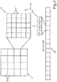
- step S4 an image region 11 around the characteristic point is defined to each characteristic point, as it is schematically shown in Fig. 4 .
- the image region 11 has a size of 20x20 pixels and is divided in 16 and thus 4x4 partial regions 12 of the same size.
- the partial regions 12 all have a size of 5x5 pixels 13.
- a descriptive vector 14 is generated to each partial region 12, which includes four vector components K1, K2, K3, K4.
- the partial region 12 is convolved by means of a convolution matrix both in x-direction and in y-direction.
- a convolution matrix both in x-direction and in y-direction.
- overall two gradient matrices are provided as results of the convolution to each partial region 12.
- the Haar wavelet is used as the convolution matrix.
- each gradient matrix has a size of 5x5.
- the vector components K1, K2, K3, K4 are calculated as follows: as the first vector component K1, a sum of the components of the gradient matrix is calculated, which is provided by convolution of the partial region 12 in x-direction. As the second vector component K2, a sum of the components of the gradient matrix is calculated, which is generated by convolution of the partial region 12 in y-direction.
- the third vector component K3 is an absolute value of the first vector component K1 and the fourth vector component K4 is an absolute value of the second vector component K2.
- the overall vector 15 represents the descriptive data of the characteristic point.
- a reduction of the size of the overall vector 15 can be performed.
- the linear discriminant analysis (LDA) is used, and the size of the overall vector 15 can for example be reduced from 64 to 48. This reduction can also be performed depending on the complexity of the structure of the imaged scene and thus of the environment 5. If the imaged scene has a relatively complex structure, a longer overall vector 15 can be provided. If the complexity of the scene is relatively low and the scene is therefore uniform, a greater reduction can be performed.
- the overall vector 15 is generated to each characteristic point in its dominant scale level 8. This means that the dominant scale level 8 is found to each characteristic point, which can for example be performed by means of the non-maximum suppression method.
- the overall vector 15 is dependent on scale. However, it is independent of a rotation of the feature images 9 because it can be assumed in the motor vehicle 1, that the scene does not rotate significantly during the movement. Thus, rotation invariance of the descriptive vectors 14 and of the overall vector 15 is omitted. Therefore, the computing time is again considerably reduced compared to the prior art, such that implementation of the tracking of the points in real time is allowed.
- step S5 the matching of the characteristic points of the first image I1 to the characteristic points of the second image I2 is effected based on the respective overall vectors 15.
- step S51 the characteristic points are classified and thus divided in two groups according to step S51. The dark points on a bright background (dark blobs) are combined to a first group, while the bright points on a dark background (bright blobs) are combined to a second group.
- the characteristic points are compared to each other in group-specific manner such that in a step S52, the points within the first group are compared to each other, and in a step S53, the points within the second group are compared to each other.
- the points are exclusively compared to those points, which belong to the same scale level 8 or the dominant scale level 8 of which is one level higher or lower.
- the comparison of the points is effected with respect to the overall vectors 15 such that the respective overall vectors 15 are compared to each other.
- a correlation can be calculated.
Landscapes
- Engineering & Computer Science (AREA)
- Multimedia (AREA)
- Physics & Mathematics (AREA)
- General Physics & Mathematics (AREA)
- Theoretical Computer Science (AREA)
- Computer Vision & Pattern Recognition (AREA)
- Image Analysis (AREA)
Claims (12)
- Verfahren zum Abgleichen von charakteristischen Punkten über wenigstens ein erstes und ein zweites Bild (I1, I2) eines Umgebungsbereichs (5) eines Kraftfahrzeugs (1), wobei die Bilder (I1, I2) mittels einer Kamera (3) des Kraftfahrzeugs (1) bereitgestellt werden und wobei an jedem Bild (I1, I2) die folgenden Schritte mithilfe einer elektronischen Bildverarbeitungsvorrichtung (4) durchgeführt werden:- Bereitstellen einer mehrskaligen Darstellung (7) des Bildes (I1, I2) mit wenigstens zwei Skalenebenen (8),- zu jeder Skalenebene (8), Bereitstellen eines Merkmalbildes (9), indem charakteristische Punkte aus dem Bild (I1, I2) auf der jeweiligen Skalenebene (8) extrahiert werden,- zu jedem charakteristischen Punkt, Finden einer dominanten Skalenebene (8) für den Punkt, und- zu jedem charakteristischen Punkt, Erzeugen jeweiliger beschreibender Daten (15) des Punktes basierend auf einem Bildbereich (11) rund um den Punkt auf der dominanten Skalenebene (8),wobei die charakteristischen Punkte des ersten Bildes (I1) jeweils mit einem charakteristischen Punkt des zweiten Bildes (I2) abgeglichen werden, basierend auf den jeweiligen beschreibenden Daten (15),
dadurch gekennzeichnet, dass
ohne Rotationsanpassung der beschreibenden Daten (15) die beschreibenden Daten (15) basierend auf der mehrskaligen Darstellung (7) erzeugt werden, während die Erzeugung der beschreibenden Daten (15) basierend auf dem jeweiligen Bildbereich (11) beinhaltet, dass der Bildbereich (11) einer Faltung mittels einer vorbestimmten Faltmatrix unterzogen wird, und wobei wenigstens eine Gradientenmatrix als Ergebnis der Faltung bereitgestellt wird, wobei die beschreibenden Daten (15) basierend auf wenigstens einer Gradientenmatrix erzeugt werden, und
der Bildbereich (11) in mehrere Teilbereiche (12) unterteilt ist und zu jedem Teilbereich (12) wenigstens jeweils eine Gradientenmatrix durch Faltung des jeweiligen Teilbereichs (12) in wenigstens eine Richtung bereitgestellt wird, wobei die beschreibenden Daten (15) in Abhängigkeit von den Gradientenmatrizen aller Teilbereiche (12) erzeugt werden,
wobei das Abgleichen der charakteristischen Punkte des ersten Bildes (I1) mit den charakteristischen Punkten des zweiten Bildes (I2) beinhaltet, dass die charakteristischen Punkte des ersten und des zweiten Bildes (I1, I2) in ein erste Gruppe mit dunklen Punkten vor einem hellen Hintergrund und eine zweite Gruppe mit hellen Punkten vor einem dunklen Hintergrund unterteilt sind, wobei die Punkte des ersten Bildes (I1) mit den Punkten des zweiten Bildes (I2) in Bezug auf die jeweiligen beschreibenden Daten (15) ausschließlich innerhalb derselben Gruppe verglichen werden. - Verfahren nach Anspruch 1,
dadurch gekennzeichnet, dass
die beschreibenden Daten (15) des jeweiligen Punktes basierend auf einem Bildbereich (11) erzeugt werden, dessen Größe insbesondere in einem Wertebereich von 16x16 Bildpunkte (13) bis 24x24 Bildpunkte (13) liegt und insbesondere 20x20 Bildpunkte (13) beträgt. - Verfahren nach Anspruch 2,
dadurch gekennzeichnet, dass
als Faltmatrix ein Wavelet, insbesondere ein Haar-Wavelet, oder ein morphologischer Operator oder ein Prewitt-Operator oder ein Sobel-Operator verwendet wird. - Verfahren nach Anspruch 3,
dadurch gekennzeichnet, dass
zu jedem Teilbereich (12) zwei Gradientenmatrizen durch Faltung des jeweiligen Teilbereichs (12) in beide Richtungen (x, y) bereitgestellt werden. - Verfahren nach Anspruch 4,
dadurch gekennzeichnet, dass
zu jedem Teilbereich (12) jeweils ein beschreibender Vektor (14) mit wenigstens zwei Vektorkomponenten (K1, K2, K3, K4) definiert ist und die beschreibenden Daten (15) als übergeordneter Vektor (15) definiert sind, der die Vektorkomponenten (K1, K2, K3, K4) der beschreibenden Vektoren (14) aller Teilbereiche (12) beinhaltet. - Verfahren nach Anspruch 5,
dadurch gekennzeichnet, dass
der beschreibende Vektor (14) jedes Teilbereichs (12) aus den folgenden Vektorkomponenten (K1, K2, K3, K4) gebildet wird:- eine erste Vektorkomponente (K1, K2, K3, K4) als Summe aller Komponenten einer Gradientenmatrix, die durch die Faltung des Teilbereichs (12) in einer ersten Richtung bereitgestellt wird, und/oder- eine zweite Vektorkomponente (K1, K2, K3, K4) als Summe aller Komponenten einer Gradientenmatrix, die durch die Faltung des Teilbereichs (12) in einer zweiten Richtung bereitgestellt wird, und/oder- eine dritte Vektorkomponente (K1, K2, K3, K4) als Absolutwert der ersten Vektorkomponente (K1, K2, K3, K4), und/oder- eine vierte Vektorkomponente (K1, K2, K3, K4) als Absolutwert der zweiten Vektorkomponente (K1, K2, K3, K4) . - Verfahren nach einem der vorhergehenden Ansprüche,
dadurch gekennzeichnet, dass
die beschreibenden Daten (15), insbesondere der übergeordnete Vektor, mittels eines Verfahrens der Hauptkomponenten-Analyse und/oder der linearen Trennanalyse komprimiert werden. - Verfahren nach einem der vorhergehenden Ansprüche,
dadurch gekennzeichnet, dass
das Abgleichen der charakteristischen Punkte des ersten Bildes (I1) mit den charakteristischen Punkten des zweiten Bildes (I2) basierend auf den jeweiligen beschreibenden Daten (15) beinhaltet, dass die charakteristischen Punkte des ersten Bildes (I1) mit den charakteristischen Punkten des zweiten Bildes (I2) in Bezug auf die jeweiligen beschreibenden Daten (15) verglichen werden, wobei ausschließlich Punkte miteinander verglichen werden, die derselben Skalenebene (8) oder unmittelbar angrenzenden Skalenebenen (8) angehören. - Verfahren nach einem der vorhergehenden Ansprüche,
dadurch gekennzeichnet, dass
als Merkmalbilder (9) werden Blob-Bilder bereitgestellt, insbesondere unter Verwendung einer Hesse-Matrix (H). - Verfahren nach einem der vorhergehenden Ansprüche,
dadurch gekennzeichnet, dass
das Finden der dominanten Skalenebene (8) für jeden charakteristischen Punkt unter Verwendung eines Nicht-Maxima-Unterdrückungsfilters bewirkt wird. - Kamerasystem (2) für ein Kraftfahrzeug (1), das eine Kamera (3) aufweist, um eine Folge von Bildern (I1, I2) eines Umgebungsbereichs (5) des Kraftfahrzeugs (1) bereitzustellen, und das eine elektronische Bildverarbeitungsvorrichtung (4) aufweist, die dafür ausgelegt ist, ein Verfahren nach einem der vorhergehenden Ansprüche durchzuführen.
- Kraftfahrzeug (1), das ein Kamerasystem (2) nach Anspruch 11 aufweist.
Applications Claiming Priority (1)
| Application Number | Priority Date | Filing Date | Title |
|---|---|---|---|
| DE102013011843.3A DE102013011843A1 (de) | 2013-07-16 | 2013-07-16 | Verfahren zum Verfolgen von charakteristischen Punkten über eine Sequenz von Bildern, Kamerasystem und Kraftfahrzeug |
Publications (2)
| Publication Number | Publication Date |
|---|---|
| EP2827281A1 EP2827281A1 (de) | 2015-01-21 |
| EP2827281B1 true EP2827281B1 (de) | 2019-01-16 |
Family
ID=50774711
Family Applications (1)
| Application Number | Title | Priority Date | Filing Date |
|---|---|---|---|
| EP14169768.0A Active EP2827281B1 (de) | 2013-07-16 | 2014-05-26 | Verfahren zum Verfolgen von charakteristischen Punkten über eine Sequenz von Bildern, Kamerasystem und Kraftfahrzeug |
Country Status (2)
| Country | Link |
|---|---|
| EP (1) | EP2827281B1 (de) |
| DE (1) | DE102013011843A1 (de) |
Family Cites Families (1)
| Publication number | Priority date | Publication date | Assignee | Title |
|---|---|---|---|---|
| DE102009019399B4 (de) * | 2009-04-29 | 2015-09-24 | Audi Ag | Verfahren zur automatischen Bestimmung wenigstens einer die Änderung der Lage eines Kraftfahrzeugs beschreibenden Zielgröße |
-
2013
- 2013-07-16 DE DE102013011843.3A patent/DE102013011843A1/de not_active Withdrawn
-
2014
- 2014-05-26 EP EP14169768.0A patent/EP2827281B1/de active Active
Non-Patent Citations (1)
| Title |
|---|
| None * |
Also Published As
| Publication number | Publication date |
|---|---|
| DE102013011843A1 (de) | 2015-01-22 |
| EP2827281A1 (de) | 2015-01-21 |
Similar Documents
| Publication | Publication Date | Title |
|---|---|---|
| Choi et al. | Thermal image enhancement using convolutional neural network | |
| US9336574B2 (en) | Image super-resolution for dynamic rearview mirror | |
| CN103914810B (zh) | 用于动态后视镜的图像超分辨率 | |
| US10452922B2 (en) | IR or thermal image enhancement method based on background information for video analysis | |
| WO2003009579A3 (en) | Computational methods for the segmentation of images of objects from background in a flow imaging instrument | |
| US20110050940A1 (en) | Method for efficient target detection from images robust to occlusion | |
| CN109492543A (zh) | 红外图像的小目标检测方法与系统 | |
| Schnelle et al. | Enhanced target tracking through infrared-visible image fusion | |
| US9392146B2 (en) | Apparatus and method for extracting object | |
| JP5906696B2 (ja) | 車両周辺撮影装置および車両周辺画像の処理方法 | |
| Tasson et al. | FPGA-based pedestrian detection under strong distortions | |
| EP2827281A1 (de) | Verfahren zum Verfolgen von charakteristischen Punkten über eine Sequenz von Bildern, Kamerasystem und Kraftfahrzeug | |
| CN106611417B (zh) | 将视觉元素分类为前景或背景的方法及装置 | |
| Blum et al. | Multisensor concealed weapon detection by using a multiresolution mosaic approach | |
| CN106971186B (zh) | 一种智能交通监控系统 | |
| Sahoo et al. | Moving object detection using background subtraction in wavelet domain | |
| Tazeem et al. | Improving security surveillance by hidden cameras | |
| KR20180061695A (ko) | 휠 검출을 통한 차량 옆면 인식 방법 및 장치 | |
| Fahmy et al. | Fast Dual Discrete and Complexwavelet Based Video Magnification for 3D Facial Video Identification | |
| Ezekiel et al. | No-reference objective blur metric based on the notion of wavelet gradient, magnitude edge width | |
| Prakash et al. | Vehicle license plate detection and recognition using non-blind image de-blurring algorithm | |
| Harrity et al. | No-reference multi-scale blur metric | |
| JP2010108062A (ja) | 物体認識装置 | |
| Moustafa et al. | A new approach for license plate detection and localization: Between reality and applicability | |
| Ansari et al. | A Survey on Blurred Images with Restoration and Transformation Techniques |
Legal Events
| Date | Code | Title | Description |
|---|---|---|---|
| 17P | Request for examination filed |
Effective date: 20140526 |
|
| AK | Designated contracting states |
Kind code of ref document: A1 Designated state(s): AL AT BE BG CH CY CZ DE DK EE ES FI FR GB GR HR HU IE IS IT LI LT LU LV MC MK MT NL NO PL PT RO RS SE SI SK SM TR |
|
| AX | Request for extension of the european patent |
Extension state: BA ME |
|
| PUAI | Public reference made under article 153(3) epc to a published international application that has entered the european phase |
Free format text: ORIGINAL CODE: 0009012 |
|
| R17P | Request for examination filed (corrected) |
Effective date: 20150721 |
|
| RBV | Designated contracting states (corrected) |
Designated state(s): AL AT BE BG CH CY CZ DE DK EE ES FI FR GB GR HR HU IE IS IT LI LT LU LV MC MK MT NL NO PL PT RO RS SE SI SK SM TR |
|
| STAA | Information on the status of an ep patent application or granted ep patent |
Free format text: STATUS: EXAMINATION IS IN PROGRESS |
|
| 17Q | First examination report despatched |
Effective date: 20170824 |
|
| GRAP | Despatch of communication of intention to grant a patent |
Free format text: ORIGINAL CODE: EPIDOSNIGR1 |
|
| STAA | Information on the status of an ep patent application or granted ep patent |
Free format text: STATUS: GRANT OF PATENT IS INTENDED |
|
| RIC1 | Information provided on ipc code assigned before grant |
Ipc: G06K 9/00 20060101AFI20180723BHEP Ipc: G06T 7/246 20170101ALI20180723BHEP Ipc: G06K 9/46 20060101ALI20180723BHEP |
|
| INTG | Intention to grant announced |
Effective date: 20180816 |
|
| RIN1 | Information on inventor provided before grant (corrected) |
Inventor name: HUGHES, CIARAN Inventor name: KAPSALAS, PETROS Inventor name: HORGAN, JONATHAN Inventor name: MCDAID, PATRICK |
|
| GRAS | Grant fee paid |
Free format text: ORIGINAL CODE: EPIDOSNIGR3 |
|
| GRAA | (expected) grant |
Free format text: ORIGINAL CODE: 0009210 |
|
| STAA | Information on the status of an ep patent application or granted ep patent |
Free format text: STATUS: THE PATENT HAS BEEN GRANTED |
|
| AK | Designated contracting states |
Kind code of ref document: B1 Designated state(s): AL AT BE BG CH CY CZ DE DK EE ES FI FR GB GR HR HU IE IS IT LI LT LU LV MC MK MT NL NO PL PT RO RS SE SI SK SM TR |
|
| REG | Reference to a national code |
Ref country code: GB Ref legal event code: FG4D |
|
| REG | Reference to a national code |
Ref country code: CH Ref legal event code: EP |
|
| REG | Reference to a national code |
Ref country code: IE Ref legal event code: FG4D |
|
| REG | Reference to a national code |
Ref country code: DE Ref legal event code: R096 Ref document number: 602014039902 Country of ref document: DE |
|
| REG | Reference to a national code |
Ref country code: AT Ref legal event code: REF Ref document number: 1090255 Country of ref document: AT Kind code of ref document: T Effective date: 20190215 |
|
| REG | Reference to a national code |
Ref country code: NL Ref legal event code: MP Effective date: 20190116 |
|
| REG | Reference to a national code |
Ref country code: LT Ref legal event code: MG4D |
|
| PG25 | Lapsed in a contracting state [announced via postgrant information from national office to epo] |
Ref country code: NL Free format text: LAPSE BECAUSE OF FAILURE TO SUBMIT A TRANSLATION OF THE DESCRIPTION OR TO PAY THE FEE WITHIN THE PRESCRIBED TIME-LIMIT Effective date: 20190116 |
|
| REG | Reference to a national code |
Ref country code: AT Ref legal event code: MK05 Ref document number: 1090255 Country of ref document: AT Kind code of ref document: T Effective date: 20190116 |
|
| PG25 | Lapsed in a contracting state [announced via postgrant information from national office to epo] |
Ref country code: LT Free format text: LAPSE BECAUSE OF FAILURE TO SUBMIT A TRANSLATION OF THE DESCRIPTION OR TO PAY THE FEE WITHIN THE PRESCRIBED TIME-LIMIT Effective date: 20190116 Ref country code: SE Free format text: LAPSE BECAUSE OF FAILURE TO SUBMIT A TRANSLATION OF THE DESCRIPTION OR TO PAY THE FEE WITHIN THE PRESCRIBED TIME-LIMIT Effective date: 20190116 Ref country code: PT Free format text: LAPSE BECAUSE OF FAILURE TO SUBMIT A TRANSLATION OF THE DESCRIPTION OR TO PAY THE FEE WITHIN THE PRESCRIBED TIME-LIMIT Effective date: 20190516 Ref country code: NO Free format text: LAPSE BECAUSE OF FAILURE TO SUBMIT A TRANSLATION OF THE DESCRIPTION OR TO PAY THE FEE WITHIN THE PRESCRIBED TIME-LIMIT Effective date: 20190416 Ref country code: ES Free format text: LAPSE BECAUSE OF FAILURE TO SUBMIT A TRANSLATION OF THE DESCRIPTION OR TO PAY THE FEE WITHIN THE PRESCRIBED TIME-LIMIT Effective date: 20190116 Ref country code: PL Free format text: LAPSE BECAUSE OF FAILURE TO SUBMIT A TRANSLATION OF THE DESCRIPTION OR TO PAY THE FEE WITHIN THE PRESCRIBED TIME-LIMIT Effective date: 20190116 Ref country code: FI Free format text: LAPSE BECAUSE OF FAILURE TO SUBMIT A TRANSLATION OF THE DESCRIPTION OR TO PAY THE FEE WITHIN THE PRESCRIBED TIME-LIMIT Effective date: 20190116 |
|
| PG25 | Lapsed in a contracting state [announced via postgrant information from national office to epo] |
Ref country code: IS Free format text: LAPSE BECAUSE OF FAILURE TO SUBMIT A TRANSLATION OF THE DESCRIPTION OR TO PAY THE FEE WITHIN THE PRESCRIBED TIME-LIMIT Effective date: 20190516 Ref country code: BG Free format text: LAPSE BECAUSE OF FAILURE TO SUBMIT A TRANSLATION OF THE DESCRIPTION OR TO PAY THE FEE WITHIN THE PRESCRIBED TIME-LIMIT Effective date: 20190416 Ref country code: RS Free format text: LAPSE BECAUSE OF FAILURE TO SUBMIT A TRANSLATION OF THE DESCRIPTION OR TO PAY THE FEE WITHIN THE PRESCRIBED TIME-LIMIT Effective date: 20190116 Ref country code: LV Free format text: LAPSE BECAUSE OF FAILURE TO SUBMIT A TRANSLATION OF THE DESCRIPTION OR TO PAY THE FEE WITHIN THE PRESCRIBED TIME-LIMIT Effective date: 20190116 Ref country code: GR Free format text: LAPSE BECAUSE OF FAILURE TO SUBMIT A TRANSLATION OF THE DESCRIPTION OR TO PAY THE FEE WITHIN THE PRESCRIBED TIME-LIMIT Effective date: 20190417 Ref country code: HR Free format text: LAPSE BECAUSE OF FAILURE TO SUBMIT A TRANSLATION OF THE DESCRIPTION OR TO PAY THE FEE WITHIN THE PRESCRIBED TIME-LIMIT Effective date: 20190116 |
|
| REG | Reference to a national code |
Ref country code: DE Ref legal event code: R097 Ref document number: 602014039902 Country of ref document: DE |
|
| PG25 | Lapsed in a contracting state [announced via postgrant information from national office to epo] |
Ref country code: DK Free format text: LAPSE BECAUSE OF FAILURE TO SUBMIT A TRANSLATION OF THE DESCRIPTION OR TO PAY THE FEE WITHIN THE PRESCRIBED TIME-LIMIT Effective date: 20190116 Ref country code: SK Free format text: LAPSE BECAUSE OF FAILURE TO SUBMIT A TRANSLATION OF THE DESCRIPTION OR TO PAY THE FEE WITHIN THE PRESCRIBED TIME-LIMIT Effective date: 20190116 Ref country code: AL Free format text: LAPSE BECAUSE OF FAILURE TO SUBMIT A TRANSLATION OF THE DESCRIPTION OR TO PAY THE FEE WITHIN THE PRESCRIBED TIME-LIMIT Effective date: 20190116 Ref country code: EE Free format text: LAPSE BECAUSE OF FAILURE TO SUBMIT A TRANSLATION OF THE DESCRIPTION OR TO PAY THE FEE WITHIN THE PRESCRIBED TIME-LIMIT Effective date: 20190116 Ref country code: IT Free format text: LAPSE BECAUSE OF FAILURE TO SUBMIT A TRANSLATION OF THE DESCRIPTION OR TO PAY THE FEE WITHIN THE PRESCRIBED TIME-LIMIT Effective date: 20190116 Ref country code: RO Free format text: LAPSE BECAUSE OF FAILURE TO SUBMIT A TRANSLATION OF THE DESCRIPTION OR TO PAY THE FEE WITHIN THE PRESCRIBED TIME-LIMIT Effective date: 20190116 Ref country code: AT Free format text: LAPSE BECAUSE OF FAILURE TO SUBMIT A TRANSLATION OF THE DESCRIPTION OR TO PAY THE FEE WITHIN THE PRESCRIBED TIME-LIMIT Effective date: 20190116 Ref country code: CZ Free format text: LAPSE BECAUSE OF FAILURE TO SUBMIT A TRANSLATION OF THE DESCRIPTION OR TO PAY THE FEE WITHIN THE PRESCRIBED TIME-LIMIT Effective date: 20190116 |
|
| PLBE | No opposition filed within time limit |
Free format text: ORIGINAL CODE: 0009261 |
|
| STAA | Information on the status of an ep patent application or granted ep patent |
Free format text: STATUS: NO OPPOSITION FILED WITHIN TIME LIMIT |
|
| PG25 | Lapsed in a contracting state [announced via postgrant information from national office to epo] |
Ref country code: SM Free format text: LAPSE BECAUSE OF FAILURE TO SUBMIT A TRANSLATION OF THE DESCRIPTION OR TO PAY THE FEE WITHIN THE PRESCRIBED TIME-LIMIT Effective date: 20190116 |
|
| 26N | No opposition filed |
Effective date: 20191017 |
|
| REG | Reference to a national code |
Ref country code: CH Ref legal event code: PL |
|
| PG25 | Lapsed in a contracting state [announced via postgrant information from national office to epo] |
Ref country code: MC Free format text: LAPSE BECAUSE OF FAILURE TO SUBMIT A TRANSLATION OF THE DESCRIPTION OR TO PAY THE FEE WITHIN THE PRESCRIBED TIME-LIMIT Effective date: 20190116 Ref country code: CH Free format text: LAPSE BECAUSE OF NON-PAYMENT OF DUE FEES Effective date: 20190531 Ref country code: LI Free format text: LAPSE BECAUSE OF NON-PAYMENT OF DUE FEES Effective date: 20190531 |
|
| REG | Reference to a national code |
Ref country code: BE Ref legal event code: MM Effective date: 20190531 |
|
| PG25 | Lapsed in a contracting state [announced via postgrant information from national office to epo] |
Ref country code: LU Free format text: LAPSE BECAUSE OF NON-PAYMENT OF DUE FEES Effective date: 20190526 Ref country code: SI Free format text: LAPSE BECAUSE OF FAILURE TO SUBMIT A TRANSLATION OF THE DESCRIPTION OR TO PAY THE FEE WITHIN THE PRESCRIBED TIME-LIMIT Effective date: 20190116 |
|
| PG25 | Lapsed in a contracting state [announced via postgrant information from national office to epo] |
Ref country code: TR Free format text: LAPSE BECAUSE OF FAILURE TO SUBMIT A TRANSLATION OF THE DESCRIPTION OR TO PAY THE FEE WITHIN THE PRESCRIBED TIME-LIMIT Effective date: 20190116 |
|
| PG25 | Lapsed in a contracting state [announced via postgrant information from national office to epo] |
Ref country code: IE Free format text: LAPSE BECAUSE OF NON-PAYMENT OF DUE FEES Effective date: 20190526 |
|
| PG25 | Lapsed in a contracting state [announced via postgrant information from national office to epo] |
Ref country code: BE Free format text: LAPSE BECAUSE OF NON-PAYMENT OF DUE FEES Effective date: 20190531 |
|
| PG25 | Lapsed in a contracting state [announced via postgrant information from national office to epo] |
Ref country code: CY Free format text: LAPSE BECAUSE OF FAILURE TO SUBMIT A TRANSLATION OF THE DESCRIPTION OR TO PAY THE FEE WITHIN THE PRESCRIBED TIME-LIMIT Effective date: 20190116 |
|
| PG25 | Lapsed in a contracting state [announced via postgrant information from national office to epo] |
Ref country code: MT Free format text: LAPSE BECAUSE OF FAILURE TO SUBMIT A TRANSLATION OF THE DESCRIPTION OR TO PAY THE FEE WITHIN THE PRESCRIBED TIME-LIMIT Effective date: 20190116 Ref country code: HU Free format text: LAPSE BECAUSE OF FAILURE TO SUBMIT A TRANSLATION OF THE DESCRIPTION OR TO PAY THE FEE WITHIN THE PRESCRIBED TIME-LIMIT; INVALID AB INITIO Effective date: 20140526 |
|
| REG | Reference to a national code |
Ref country code: DE Ref legal event code: R079 Ref document number: 602014039902 Country of ref document: DE Free format text: PREVIOUS MAIN CLASS: G06K0009000000 Ipc: G06V0010000000 |
|
| PG25 | Lapsed in a contracting state [announced via postgrant information from national office to epo] |
Ref country code: MK Free format text: LAPSE BECAUSE OF FAILURE TO SUBMIT A TRANSLATION OF THE DESCRIPTION OR TO PAY THE FEE WITHIN THE PRESCRIBED TIME-LIMIT Effective date: 20190116 |
|
| P01 | Opt-out of the competence of the unified patent court (upc) registered |
Effective date: 20230528 |
|
| PGFP | Annual fee paid to national office [announced via postgrant information from national office to epo] |
Ref country code: DE Payment date: 20250513 Year of fee payment: 12 |
|
| PGFP | Annual fee paid to national office [announced via postgrant information from national office to epo] |
Ref country code: GB Payment date: 20250521 Year of fee payment: 12 |
|
| PGFP | Annual fee paid to national office [announced via postgrant information from national office to epo] |
Ref country code: FR Payment date: 20250530 Year of fee payment: 12 |