EP2827263A1 - Structure component shape optimization analysis device - Google Patents
Structure component shape optimization analysis device Download PDFInfo
- Publication number
- EP2827263A1 EP2827263A1 EP13761395.6A EP13761395A EP2827263A1 EP 2827263 A1 EP2827263 A1 EP 2827263A1 EP 13761395 A EP13761395 A EP 13761395A EP 2827263 A1 EP2827263 A1 EP 2827263A1
- Authority
- EP
- European Patent Office
- Prior art keywords
- rigidity
- shape
- cross
- structural body
- analysis
- Prior art date
- Legal status (The legal status is an assumption and is not a legal conclusion. Google has not performed a legal analysis and makes no representation as to the accuracy of the status listed.)
- Granted
Links
Images






Classifications
-
- G—PHYSICS
- G06—COMPUTING OR CALCULATING; COUNTING
- G06F—ELECTRIC DIGITAL DATA PROCESSING
- G06F30/00—Computer-aided design [CAD]
- G06F30/10—Geometric CAD
- G06F30/15—Vehicle, aircraft or watercraft design
-
- G—PHYSICS
- G06—COMPUTING OR CALCULATING; COUNTING
- G06F—ELECTRIC DIGITAL DATA PROCESSING
- G06F30/00—Computer-aided design [CAD]
-
- G—PHYSICS
- G06—COMPUTING OR CALCULATING; COUNTING
- G06F—ELECTRIC DIGITAL DATA PROCESSING
- G06F30/00—Computer-aided design [CAD]
- G06F30/10—Geometric CAD
- G06F30/17—Mechanical parametric or variational design
-
- G—PHYSICS
- G06—COMPUTING OR CALCULATING; COUNTING
- G06F—ELECTRIC DIGITAL DATA PROCESSING
- G06F30/00—Computer-aided design [CAD]
- G06F30/20—Design optimisation, verification or simulation
-
- G—PHYSICS
- G06—COMPUTING OR CALCULATING; COUNTING
- G06F—ELECTRIC DIGITAL DATA PROCESSING
- G06F2111/00—Details relating to CAD techniques
- G06F2111/06—Multi-objective optimisation, e.g. Pareto optimisation using simulated annealing [SA], ant colony algorithms or genetic algorithms [GA]
-
- G—PHYSICS
- G06—COMPUTING OR CALCULATING; COUNTING
- G06F—ELECTRIC DIGITAL DATA PROCESSING
- G06F2111/00—Details relating to CAD techniques
- G06F2111/10—Numerical modelling
Definitions
- the present invention relates to an optimization analyzing apparatus for a shape of a part of a structural body, which optimizes a shape of a part (hereinafter, also referred to as "structural part”) that forms a structural body such as an automotive body, for example.
- CAE analysis computer-aided engineering
- the CAE analysis has been known as an analytical technique capable of improving rigidity of a structural body or achieving the weight reduction of an automotive body by using an optimization technique such as mathematical optimizers, a plate thickness optimization method, a shape optimization method, or a topology optimization method (see, for example, Patent Document 1).
- an optimization technique such as mathematical optimizers, a plate thickness optimization method, a shape optimization method, or a topology optimization method (see, for example, Patent Document 1).
- an optimization method that equally changes a shape of a structural part by using a representative dimension of the structural part has been used generally.
- Patent Literature 1 Japanese Laid-open Patent Application No. 2006-330917
- the conventionally performed shape optimization method for a part of a structural body is a method of performing analysis by changing a shape of the entire part. Hence, it is impossible to obtain accurate results from this analysis. Therefore, the conventional shape optimization methods have been insufficient as optimization methods of a shape of a part. Furthermore, when a rigidity analysis is performed in optimizing a shape of a part, a method of analyzing by determining load and constraint conditions suitable to the part alone has been conventionally general. Hence, load transfer or the like when that part is incorporated in a structural body such as an automotive body is not reproduced correctly. Therefore, the shape optimization methods of structural parts have been insufficient.
- the present invention has been made in order to solve the above problem and its object is to obtain an optimization analyzing apparatus for a shape of a structural part, which uses a multivariate analysis and is able to accurately optimize a shape of a part of a structural body.
- an optimization analyzing apparatus for a shape of a part of a structural body is configured of a computer and includes: a part shape pattern setting device that divides a part of a structural body including a two-dimensional element and/or a three-dimensional element into a plurality of segments in an axis direction, changes a height or width of a cross section of each of the segments divided, and sets a part shape pattern; a rigidity analyzing device that performs plural kinds of rigidity analyses of the structural body in a state in which the part for which the part shape pattern has been set by the part shape pattern setting device is incorporated in the structural body and obtains any of: rigidity; improvement rate of rigidity; and improvement rate of rigidity per increased unit weight, of the structural body for each kind of the rigidity analyses; a multivariate analyzing device that performs a multivariate analysis for each kind of the rigidity analyses where any of the rigidity, the improvement rate of rigidity, and the improvement rate of rigidity
- An optimization analyzing apparatus for a shape of a part of a structural body is characterized in that, in the above-mentioned invention, the multivariate analyzing device calculates a standard partial regression coefficient, and the optimization analyzing apparatus further comprises a shape change priority determination device that determines, based on the standard partial regression coefficient, a priority of change in shape of each segment for each of the plural kinds of rigidity analyses.
- An optimization analyzing apparatus for s shape of s part of s structural body is characterized in that in the above-mentioned invention, the cross-sectional shape determination device determines a shape of a boundary portion of each of the segments divided or a shape in the vicinity of the boundary portion to be a gradually changing shape.
- the present invention realizes an advantageous effect such that optimization for a shape of a structural part can be accurately performed.
- optimization analyzing apparatus for a shape of a structural part (hereinafter, simply referred to as “optimization analyzing apparatus”) according to the present invention are explained in detail referring to drawings.
- An optimization analyzing apparatus 1 is an apparatus for performing optimized calculation by numerical analysis with respect to a shape of a part of a structural body constituted with two-dimensional elements and/or three-dimensional elements.
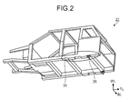
- the structural body in the present embodiment includes, as an example, an automotive body 31 illustrated in FIG. 2 .
- the part that constitutes the structural body in the present embodiment includes, as an example, a rear side member 33 illustrated in FIG. 3 or the like. Furthermore, in the present embodiment, as illustrated in FIG.
- the width direction of the automotive body 31 is referred to as a BL direction
- the height direction of the automotive body 31 is referred to as a WL direction
- the longitudinal direction of the automotive body 31 is referred to as a TL direction.
- the rear side member 33 is, as illustrated in an area surrounded by an ellipse in FIG. 2 , a part that constitutes a rearward lower portion of the automotive body 31. Only the rear side member 33 separated from the automotive body 31 is illustrated in FIG. 3 .
- the rear side member 33 is, as illustrated in FIG. 3 and FIG. 4 , a long strip-shaped hat cross-sectional part.
- the rear side member 33 has, as illustrated in FIG. 3 , a coiled spring leg 35.
- the coiled spring leg 35 supports a coiled spring mounted on a lower surface in the vicinity of one end portion of the rear side member 33.
- the rear side member 33 is, as illustrated in FIG.
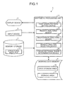
- the optimization analyzing apparatus 1 is constituted of a personal computer (PC) and has, as illustrated in FIG. 1 , a display device 3, an input device 5, a memory storage 7, a working data memory 9, and an arithmetic processing unit 11. Furthermore, the arithmetic processing unit 11 connects thereto the display device 3, the input device 5, the memory storage 7, and the working data memory 9. The display device 3, the input device 5, the memory storage 7, and the working data memory 9 respectively perform functions in response to instructions of the arithmetic processing unit 11.
- PC personal computer
- the display device 3 displays thereon various kinds of information such as input information by the input device 5 and results of calculating by the arithmetic processing unit 11.
- the display device 3 is constituted by using a liquid crystal display (LCD) monitor or the like.
- the input device 5 inputs, in response to input operations by an operator, various kinds of information such as instruction information for instructing the display of a structural body file 13 in the memory storage 7 and analysis conditions.
- the input device 5 is constituted by using a keyboard, a mouse, or the like.
- the memory storage 7 stores therein at least various kinds of information such as the structural body file 13.
- the structural body file 13 is information indicative of types, combinations, or the like of respective elements that constitute a structural body.
- the structural body may be constituted only of two-dimensional elements or only of three-dimensional elements, or may be constituted of two-dimensional elements and three-dimensional elements that are combined with each other.
- the automotive body 31 designated as an example of the structural body is, as illustrated in FIG. 2 , mainly formed by steel sheet. That is, the automotive body 31 is mainly constituted of two-dimensional elements.
- a block body or the like may be formed of three-dimensional elements.
- the working data memory 9 has a data storage area 15 for storing calculation results and a working area 17 for performing arithmetic processing.
- the arithmetic processing unit 11 is constituted of a central processing unit (CPU) of the PC. Each device in the arithmetic processing unit 11 explained below is realized by predetermined programs executed by the CPU.
- the arithmetic processing unit 11 realizes a part shape pattern setting device 21 that divides a part of a structural body constituted of two-dimensional elements and/or three-dimensional elements into a plurality of portions in one axis direction and changes cross-sectional heights or widths with respect to the respective portions divided to set a part shape pattern, a rigidity analyzing device 23 that performs plural kinds of rigidity analyses for the structural body in a state that the part to which the part shape pattern is set by the part shape pattern setting device 21 is incorporated in the structural body to obtain any of the rigidity, improvement rate of rigidity, and improvement rate of rigidity per increased unit weight of the structural body for each kind of the above-mentioned rigidity analyses, a multivariate analyzing device 25 that sets any of the rigidity, improvement rate of rigidity, and improvement rate of rigidity per increased unit weight of the structural body that are obtained by the rigidity analyzing device 23 as a response variable, sets any of the height, width, and section modulus of the above-mentione
- the part shape pattern setting device 21 divides a part of a structural body constituted of two-dimensional elements and/or three-dimensional elements into a plurality of portions in one axis direction, changes a cross-sectional height or width with respect to each portion divided to set a part shape pattern.
- the part shape pattern setting device 21 divides the rear side member 33 illustrated in FIG. 3 into segments 331, 332, and 333.
- the segments 331, 332, and 333 are three portions into which the middle portion of the rear side member 33 is divided in the TL direction.
- the part shape pattern setting device 21 changes the cross-sectional heights of the respective segments 331, 332, and 333 to set the part shape pattern of the rear side member 33.
- the rear side member 33 is, as illustrated in FIG. 4 , the hat cross-sectional part having vertical wall portions 37 and a top plate portion 39.
- the change in cross-sectional height mentioned above means that the lengths of the vertical wall portions 37 in at least one of the respective segments 331, 332, and 333 of the rear side member 33 are changed to change a distance from a standard shape of the rear side member 33 to the top plate portion 39.
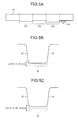
- the standard shape of the rear side member 33 is, as an example illustrated in FIG. 3 , a shape such that the outer surface of the top plate portion 39 is flat in the longitudinal direction of the rear side member 33 (in the TL direction of the automotive body 31 illustrated in FIG. 2 ).
- a displacement ⁇ H illustrated in FIGS. 5B and 5C is a displacement of the distance from the standard shape of the rear side member 33 to the top plate portion 39; that is, a displacement of the cross-sectional height from the standard shape of the rear side member 33.
- the standard shapes of the rear side member 33 are illustrated by solid lines.
- the rear side member 33 forms a shape illustrated in FIG. 6 in accordance with the setting of the displacements ⁇ H of these cross-sectional heights.
- the shape of the segment whose displacement ⁇ H is 0 mm among the segments 331, 332, and 333 is same as the standard shape of the above-mentioned rear side member 33.
- the rigidity analyzing device 23 performs plural kinds of rigidity analyses of the structural body in a state that the part to which the part shape pattern is set by the part shape pattern setting device 21 is incorporated in the structural body to be analyzed to obtain any of the rigidity, improvement rate of rigidity, and improvement rate of rigidity per increased unit weight of the structural body for each kind of the rigidity analyses.
- the kinds of a plurality of rigidity analyses performed by the rigidity analyzing device 23 for example, torsional rigidity of the automotive body 31, local rigidity at a place to which a part is attached, or the like is designated.
- Each of these plural kinds of rigidity analyses is further subdivided for each load and constraint condition.
- the rigidity is a value obtained as a result of the rigidity analysis performed by the rigidity analyzing device 23.
- the improvement rate of rigidity is an index indicating the degree of improvement of the rigidity of a structural body after setting a part shape pattern in comparison with a structural body having a standard shape.
- the improvement rate of rigidity is, for example, useful to find the degree of improvement of the rigidity of a structural body after setting a part shape pattern in comparison with a structural body having a standard shape; that is, the tendency of improvement thereof.
- the improvement rate of rigidity per increased unit weight is an index indicating the degree of improvement of the rigidity rate per increased unit weight of a structural body.
- the improvement rate of rigidity per increased unit weight is calculated by dividing the above-mentioned improvement rate of rigidity by an increased weight of a structural body or a part thereof.
- the improvement rate of rigidity per increased unit weight is useful to obtain an optimized shape of a part in consideration of the weight of the structural body.
- the rigidity analyzing device 23 in the present embodiment performed the torsional rigidity analysis and the local rigidity analysis as examples of the plural kinds of rigidity analyses.
- the rigidity analyzing device 23 incorporates, as illustrated in FIG. 7 , the rear side member 33 in the automotive body 31. Subsequently, the rigidity analyzing device 23 constrains three portions among predetermined portions 511, 512, 513, and 514 of the automotive body 31 and, at the same time, applies a predetermined load (an upward load of 0.5 kN, for example) to the other one portion as illustrated by arrows in FIG. 7 .
- the predetermined portions 511 and 512 of the automotive body 31 are, for example, as illustrated in FIG.
- the predetermined portions 513 and 514 are, for example, as illustrated in FIG. 7 , portions each of which is a portion of the above-mentioned coiled spring leg 35.
- the rigidity analyzing device 23 obtained, as described above, the torsional rigidity of the automotive body 31 by analyzing in applying the upward load to the automotive body 31.
- the rigidity analyzing device 23 sequentially changes a portion for applying the upward load in the automotive body 31 to any of the predetermined portions 511, 512, 513, and 514. Accordingly, the number of the above-mentioned load conditions of the torsional rigidity analyses becomes four (4) in total.
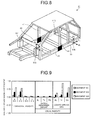
- the rigidity analyzing device 23 incorporates, as illustrated in FIG. 8 , the rear side member 33 of the automotive body 31. Subsequently, the rigidity analyzing device 23 constrains, as illustrated in FIG. 8 , a predetermined portion of the automotive body 31 such as a portion in the vicinity of a connection portion between the lower portion of a B pillar 41 located at the middle of the automotive body 31 and a side member 43 (a portion indicated by a black square in FIG. 8 ).
- the rigidity analyzing device 23 applies, while maintaining a constrained state of the automotive body 31, a load to a predetermined portion 515 or a predetermined portion 516 of the automotive body 31 in one direction chosen among the BL direction, the WL direction, and the TL direction as illustrated by arrows in FIG. 8 .
- the predetermined portion 515 of the automotive body 31 is, as illustrated in FIG. 8 , a portion such as the above-mentioned shock absorber mount.
- the predetermined portion 516 of the automotive body 31 is, as illustrated in FIG. 8 , a portion such as the above-mentioned coiled spring leg 35.
- the predetermined portion 515 or 516 may be, since the automotive body 31 has a bilaterally symmetrical shape, one of both-side shock absorber mounts or one of both-side coiled spring legs 35.
- the rigidity analyzing device 23 obtained, by applying a load to the automotive body 31 as described above, the displacement of the portion to which the load is applied in the automotive body 31 by the analysis.
- the rigidity analyzing device 23 sequentially changes a portion to which the load is applied in the automotive body 31 to any of the remaining predetermined portions 515 and 516 and, at the same time, subsequently changes the direction in which the load is applied to any of the BL direction, the WL direction, and the TL direction. Accordingly, the number of the above-mentioned load conditions of the local rigidity analyses becomes six (6) in total.
- the number of the load conditions of the torsional rigidity analyses by the rigidity analyzing device 23 is four (4). Furthermore, the number of the load conditions of the local rigidity analyses by the rigidity analyzing device 23 is six (6). Accordingly, the number of the kinds of the rigidity analyses performed by the rigidity analyzing device 23 is ten (10).
- the number of the part shape pattern of the rear side member 33 that is set by the part shape pattern setting device 21 is 36.
- the rigidity analyzing device 23 reduced the 360 kinds of rigidity analysis patterns to half based on an experimental design and analyzed 180 kinds of rigidity analysis patterns.
- An ordinary rigidity analysis requires calculations of all of the rigidity analysis patterns.
- the optimization analyzing apparatus 1 according to the present invention uses the multivariate analysis method, and can obtain reliable rigidity analysis results even when the number of the rigidity analysis pattern is reduced to half as described above.
- the multivariate analyzing device 25 sets any of the rigidity, improvement rate of rigidity, and improvement rate of rigidity per increased unit weight of a structural body that are obtained by the rigidity analyzing device 23 as a response variable, sets any of the height, width, and section modulus of each of portions into which the structural body is divided as an explanatory variable, and performs a multivariate analysis for each kind of rigidity analyses performed by the rigidity analyzing device 23 to obtain a multiple regression coefficient, and a coefficient of determination or an adjusted R-square.
- the multivariate analysis is a statistical analysis method for finding regularity by analyzing objective phenomena.
- the multivariate analyses are performed so as to find the degree of effect of the height, width, or section modulus of each of portions into which the structural body is divided on the rigidity, improvement rate of rigidity, or improvement rate of rigidity per increased unit weight of the structural body numerically and reliably.
- the multivariate analysis performed by the multivariate analyzing device 25 is specifically progressed in accordance with the following procedures. First of all, a relational expression for the multivariate analysis is made. Next, the multivariate analyzing device 25 obtains a multiple regression coefficient as a regression coefficient of the relational expression. The multivariate analyzing device 25 may obtain a standard partial regression coefficient other than the multiple regression coefficient as such a regression coefficient. Furthermore, the multivariate analyzing device 25 obtains a coefficient of determination that is an index indicating the degree of being able to explain a response variable by the relational expression or an adjusted R-square (R 2 ) in which the degree of freedom of the coefficient of determination is adjusted.
- R 2 adjusted R-square
- the multivariate analyzing device 25 sets the result of performing rigidity analyses with respect to the above-mentioned 180 rigidity analysis patterns; that is, the rigidity of the automotive body 31 as a response variable. Furthermore, the multivariate analyzing device 25 sets the cross-sectional height of each segment 331, 332, or 333 into which the rear side member 33 is divided as an explanatory variable. The multivariate analyzing device 25 creates an expression (1) as a relational expression for explaining the above-mentioned response variable with the use of the explanatory variable. The multivariate analyzing device 25 performed multivariate analyses based on the expression (1). In the expression (1), each regression coefficient ⁇ , ⁇ , or ⁇ is a multiple regression coefficient or a standard partial regression coefficient.
- a cross-sectional height H 1 is the cross-sectional height of the segment 331 of the rear side member 33.
- a cross-sectional height H 2 is the cross-sectional height of the segment 332 of the rear side member 33.
- a cross-sectional height H 3 is the cross-sectional height of the segment 333 of the rear side member 33.
- the multivariate analyzing device 25 performed the multivariate analyses of the above-mentioned 180 rigidity analysis patterns based on the expression (1). Results of the multivariate analyses are listed in Table 1. Hereinafter, results of discussion with respect to Table 1 are explained. Table 1 Torsional rigidity Local rigidity Shock absorber mount Coiled spring leg a 511 b 512 c 513 d 514 BL TL WL BL TL WL Adjusted R-square (R 2 ) 0.95 0.96 0.92 0.93 0.35 0.45 0.51 0.81 0.87 0.94 Standard partial regression coefficient Cross-sectional height H 1 0.22 0.21 0.44 0.43 -0.21 0.10 0.21 -0.31 0.06 0.05 Cross-sectional height H 2 0.35 0.36 0.33 0.32 0.51 0.46 0.40 0.30 0.11 0.15 Cross-sectional height H 3 0.51 0.50 0.25 0.25 0.30 0.44 0.38 0.31 0.93 0.88 Multiple regression coefficient Cross-sectional height H 1 0.10 0.11 0.05 0.06 -0.01 0.01 0.01
- Table 1 lists adjusted R-squares and regression coefficients (standard partial regression coefficients and multiple regression coefficients) for all kinds of 10 rigidity analyses performed in the above-mentioned rigidity analyzing device 23.
- the adjusted R-squares and the regression coefficients are separately described in the respective rows for every rigidity analysis condition and every load condition.
- the adjusted R-squares and the regression coefficients are shown when the torsional rigidity analysis is performed under the load condition that a load is applied to the predetermined portion 511 of the automotive body 31 and the other predetermined portions 512, 513, and 514 are constrained.
- “Shock absorber mount”, “Coiled spring leg”, “BL”, “TL”, and “WL” of the column of “Local rigidity” indicate load conditions in analyzing the local rigidity of the automotive body 31 illustrated in FIG. 8 .
- the "Shock absorber mount” indicates that the load-applied portion of the automotive body 31 is a portion of the shock absorber mount (the predetermined portion 515 illustrated in FIG. 8 ).
- the "Coiled spring leg” indicates that the load-applied portion of the automotive body 31 is a portion of the coiled spring leg 35 (the predetermined portion 516 illustrated in FIG. 8 ).
- the "BL” indicates that a direction in which a load is applied to the automotive body 31 is the BL direction (the width direction of the automotive body 31).
- the "TL” indicates that a direction in which a load is applied to the automotive body 31 is the TL direction (the longitudinal direction of the automotive body 31).
- the "WL” indicates that a direction in which a load is applied to the automotive body 31 is the WL direction (the height direction of the automotive body 31).
- BL the row of "BL” of the "Shock absorber mount” of the "Local rigidity”
- BL the "Shock absorber mount” of the "Local rigidity”
- adjusted R-squares and regression coefficients are shown when the local rigidity analysis is performed under the load condition that a load in the BL direction is applied to the predetermined portion 515 (the shock absorber mount) of the automotive body 31 illustrated in FIG. 8 .
- a portion in the vicinity of the joined portion between the lower portion of the B pillar 41 located in the middle of the automotive body 31 and a side member 43 is constrained.
- the adjusted R-squares are listed. In lines below the uppermost line, the standard partial regression coefficients and the multiple regression coefficients are described.
- the adjusted R-square is, in a multiple regression analysis, used for adjusting the degree of freedom of regression to prevent the tendency of a regression result to be improved by increasing the number of the explanatory variables.
- the rigidity of the automotive body 31 is obtained.
- the regression coefficients ⁇ , ⁇ , and ⁇ in the expression (1) and the adjusted R-square indicating correlation between the rigidity of the automotive body 31 and the cross-sectional heights H 1 , H 2 , and H 3 of the rear side member 33 values in the row of the "a" can be read.
- a relational expression indicating correlation between the rigidity of the automotive body 31 and the cross-sectional heights H 1 , H 2 , and H 3 of the rear side member 33 is expressed as an expression (2).
- the adjusted R-square is 0.95.
- Rigidity 0.10 ⁇ cross - sectional height H 1 + 0.31 ⁇ cross - sectional height H 2 + 0.59 ⁇ cross - sectional height H 3
- the multiple regression coefficient is, in the present embodiment, an index indicating a contribution to a rigidity.
- the multiple regression coefficient is an absolute index, the absolute indexes being capable of being compared with each other through whole analysis conditions.
- the degree of contribution of the cross-sectional height H 1 , H 2 , or H 3 of each segment 331, 332, or 333 of the rear side member 33 to the rigidity of the automotive body 31 through each analysis condition can be found.
- FIG. 9 is a plot of the multiple regression coefficients listed in Table 1 for every analysis condition and for every load condition.
- a bar graph with hatched lines corresponds to the segment 331 of the rear side member 33;
- a black bar corresponds to the segment 332 of the rear side member 33;
- a white bar corresponds to the segment 333 of the rear side member 33.
- Each of the cross-sectional heights H 2 and H 3 of the segments 332 and 333 largely contributes to the torsional rigidity of the predetermined portion 511 and the predetermined portion 512 of the automotive body 31; that is, the shock absorber mount, and the local rigidity of the coiled spring leg (the predetermined portion 516 illustrated in FIG. 8 ). Therefore, when the cross-sectional height H 3 of the segment 333 is increased, it can be found that the above-mentioned torsional rigidity or the local rigidity of the coiled spring leg is improved.
- the standard partial regression coefficient is, in the present embodiment, an index indicating a contribution of each part portion to the rigidity of the structural body.
- the standard partial regression coefficient is a relative index, the relative indexes being capable of being compared with each other only under the specific analysis condition. Referring to the standard partial regression coefficient is, in finding a degree of contribution of the cross-sectional heights H 1 , H 2 , and H 3 of the segments 331, 332, and 333 of the rear side member 33 to the rigidity of the automotive body 31 in a specific rigidity analysis, easier to understand than referring to the multiple regression coefficient.
- FIG. 10 is, in the same manner as FIG. 9 , a graph of the standard partial regression coefficient described in Table 1 for every analysis condition and for every load condition. Discussion with respect to FIG. 10 is described below.
- the cross-sectional height H 3 of the segment 333 largely contributes to the torsional rigidity in the case of the multiple regression coefficients and the standard partial regression coefficient.
- the respective contributions of the segments 331 and 332 to the rigidity of the automotive body 31 are different from each other. Particularly, the contribution of the segment 331 is small in view of the multiple regression coefficient in FIG. 9 , but large in view of the standard partial regression coefficient in FIG. 10 .
- the load condition in the torsional rigidity analysis is a load condition that a load is applied to the predetermined portion 513 (see FIG. 7 ) of the automotive body 31, in view of the multiple regression coefficient in FIG. 9 , the contributions of the segments 331, 332, and 333 to the rigidity of the automotive body 31 are small. However, in view of the standard partial regression coefficient in FIG. 10 , it can be confirmed that the contribution of the segment 331 is large. As a result of this discussion, the following can be understood; that is, when the torsional rigidity of the automotive body 31 is comprehensively evaluated with respect to all of the predetermined portions 511, 512, 513, and 514, the reinforcement of the segment 333 realizes the effect of improving the rigidity of the automotive body 31.
- the reinforcement of the segment 331 realizes the effect of improving the rigidities of the preferential portions.
- the cross-sectional height H 3 of the segment 333 largely contributes to the improvement of the local rigidity of the automotive body 31 with respect to loads in the TL direction and WL direction.
- the cross-sectional height H 2 of the segment 332 contributes to the improvement of the local rigidity of the automotive body 31 with respect to a load in the BL direction.
- the contribution of the cross-sectional height H 1 of the segment 331 to the local rigidity is small under any load conditions.
- the rigidity analysis selection device 27 selects a rigidity analysis being high in correlation among the kinds of rigidity analyses based on any of the coefficient of determination and the adjusted R-square that are obtained by the multivariate analyzing device 25. In general, it can be determined that the closer to one (1) the adjusted R-square is, the stronger the correlation of the rigidity analysis is and the higher the analysis accuracy is. In the present embodiment, as an example, the rigidity analysis in which the adjusted R-square is equal to or larger than 0.8 was determined as a rigidity analysis with high correlation and high analysis accuracy.
- the rigidity analysis selection device 27 selects rigidity analyses with high correlation; that is, in Table 1, the torsional rigidity and the local rigidity in the coiled spring leg among the plural kinds of rigidity analyses.
- the rigidity analyses selected have high correlation and thus can be determined that the rigidity analyses have high analysis accuracy. Therefore, the multiple regression coefficient obtained by each multivariate analysis of the torsional rigidity and the local rigidity in the coiled spring leg can be used as an index for determining an optimized shape of a structural part such as the rear side member 33.
- the adjusted R-square with respect to the local rigidity in the shock absorber mount is, as described in Table 1, 0.35 when a direction in which a load is applied is the BL direction, 0.45 when a direction in which a load is applied is the TL direction, and 0.51 when a direction in which a load is applied is the WL direction. Correlation of such a local rigidity analysis is moderate. Therefore, the multiple regression coefficient obtained by the multivariate analysis of the local rigidity in the shock absorber mount is not used for determining the optimized shape of a structural part.
- the cross-sectional shape determination device 29 determines the optimal cross-sectional shape of each segment of a structural part based on a multiple regression coefficient of a rigidity analysis selected by the rigidity analysis selection device 27 determining that the rigidity analysis has high analysis accuracy (strong correlation), the multiple regression coefficient being calculated by the multivariate analyzing device 25.
- the optimal shape of a cross-section of a part that is determined by the cross-sectional shape determination device 29 is displayed on the display device 3.
- the cross-sectional shape determination device 29 has an editor function for changing more specifically the determined optimal shape based on input information from the input device 5 in response to input operations by an operator.
- the rigidity analysis selection device 27 selected, as described above, each rigidity analysis of torsional rigidities and local rigidities in the coiled spring leg as kinds of rigidity analyses with strong correlation and high analysis accuracy.
- the cross-sectional shape determination device 29 determined the optimal shape of the rear side member 33 based on the multiple regression coefficient of each rigidity analysis selected. As described above, the multiple regression coefficient is an index indicating contribution to rigidity. The higher the multiple regression coefficient is, the larger the contribution to rigidity becomes.
- FIG. 11 illustrates mean values of the multiple regression coefficients for the respective rigidities for each segment 331, 332, or 333 of the rear side member 33 with respect to the torsional rigidities and the local rigidities in the coiled spring leg that are selected by the rigidity analysis selection device 27.
- the multiple regression coefficient of the segment 331 is approximately 0.05
- the multiple regression coefficient of the segment 332 is approximately 0.18
- the multiple regression coefficient of the segment 333 is approximately 0.41. That is, the segment 333 contributes to the rigidity most throughout the entire analysis.
- the segment 332 secondly contributes to the rigidity.
- the segment 331 hardly contributes to the rigidity.
- the optimal shape of the rear side member 33 may be determined based on the following conditions. Since the segment 333 contributes to a rigidity most, the cross-sectional height H 3 of the segment 333 is increased as much as possible. Since the segment 332 also contributes to the rigidity to some extent, the cross-sectional height H 2 of the segment 332 is increased.
- the cross-sectional height H 1 of the segment 331 is, in view of the reduction in weight of the automotive body 31, not increased. That is, as illustrated in FIG. 12 , the displacement ⁇ H of the cross-sectional height H 3 of the segment 333 is set to the highest level of 20 mm (see FIG. 5B ).
- the displacement ⁇ H of the cross-sectional height H 2 of the segment 332 is, in consideration of a balance with the increase in weight of the rear side member 33, set to 10 mm lower than that of the segment 333.
- the displacement ⁇ H of the cross-sectional height H 1 of the segment 331 is set to 0 mm so as to prevent the increase in weight of the rear side member 33.
- An operator may change the cross-sectional shape of the segment 331, 332, or 333 of the rear side member 33 to a further specific shape by using the cross-sectional shape determination device 29.
- a further-optimized cross-sectional shape of the segment 331, 332, or 333 may be obtained rather than the optimal shape determined by the cross-sectional shape determination device 29.
- the cross-sectional shape determination device 29 may determine a shape of the rear side member 33 illustrated in FIG. 12 as an optimal shape.
- the cross-sectional shape determination device 29 may determine the shape of a boundary portion or the shape in the vicinity of the boundary portion of each segment 331, 332, or 333 of the rear side member 33 as a gradually changing shape. To be more specific, as illustrated in FIG.
- the cross-sectional shape determination device 29 provides a gradual change zone 334 or 335 having a length (20 mm, for example) extending over the boundary portion of each segment 331, 332, or 333.
- the cross-sectional shape determination device 29 may gradually change the shape of the rear side member 33 in the gradual change zone 334 or 335. Due to such a constitution, the stress concentration on the boundary portion of each segment 331, 332, or 333 is relieved. As a result, the rigidity of the rear side member 33 as a whole and the rigidity of the automotive body 31 can be further improved.
- the cross-sectional shape determination device 29 may determine the shape of the boundary of each segment 331, 332, or 333 based on the contribution of the segment 331, 332, or 333 to the rigidity of the automotive body 31. Due to such a constitution, the rigidity of the automotive body 31 is further improved. To be more specific, as illustrated in FIG. 13B , the cross-sectional shape determination device 29 maintains, based on the contribution of the segment 331, 332, or 333 to the rigidity of the automotive body 31, the cross-sectional height H 3 of the segment 333 having a largest contribution to the rigidity as high as possible and, at the same time, provides the gradual change zone 335 having a predetermined length (10 mm, for example) only to the segment 332.
- the cross-sectional shape determination device 29 maintains the cross-sectional height H 2 of the segment 332 having a large contribution to the rigidity next to the segment 333 as high as possible and, at the same time, provides the gradual change zone 334 with a predetermined length (10 mm, for example) only to the segment 331.
- the cross-sectional shape determination device 29 may change the shape of the rear side member 33 to the optimal shape provided with the gradual change zones 334 and 335 as illustrated in FIG. 13B . Due to such a constitution, the rigidity of the automotive body 31 was further improved by 0.5%.
- the optimization analyzing apparatus 1 may be further provided with a shape change priority determination device for determining the priority of the shape change of each of plural portions into which a structural part is divided.
- the standard partial regression coefficient is, as described above, suitable as an index referred to in an attempt to achieve the improvement of the rigidity of a structural body in view of predetermined analysis conditions.
- the above-mentioned shape change priority determination device may be used.
- the part shape pattern setting device 21 is used for dividing the rear side member 33 that is a part of the automotive body 31 in the TL direction, and the cross-sectional heights of the segments 331, 332, and 333 of the rear side member 33 are changed to set a part shape pattern thereto. Furthermore, the rigidity analyzing device 23 is used to perform rigidity analysis of the automotive body 31 based on a plurality of analysis conditions in a state in which the rear side member 33 for which the part shape pattern has been set by the part shape pattern setting device 21 is incorporated in the automotive body 31, to obtain rigidity.
- the multivariate analyzing device 25 is used for performing the multivariate analysis after setting the rigidity obtained by the rigidity analyzing device 23 as a response variable and setting the cross-sectional heights H 1 , H 2 , and H 3 of the segments 331, 332, and 333 as an explanatory variable to obtain a multiple regression coefficient and an adjusted R-square.
- the rigidity analysis selection device 27 is used for selecting an analysis condition with high correlation among the above-mentioned analysis conditions based on the adjusted R-square obtained by the multivariate analyzing device 25.
- the cross-sectional shape determination device 29 is used for determining the cross-sectional shapes of the segments 331, 332, and 333 based on the values of the multiple regression coefficients of the segments 331, 332, and 333. Due to such a constitution, the shape of the rear side member 33 can be accurately optimized.
- the example is provided such that the multivariate analysis is performed after setting a rigidity as a response variable.
- an example is provided such that the improvement rate of rigidity is set as a response variable.
- the automotive body 31 illustrated in FIG. 2 is exemplified; as an example of a structural part, the rear side member 33 illustrated in FIG. 3 is exemplified.
- the part shape pattern setting device 21 is configured to divide the intermediate portion of the rear side member 33 into three portions of the segments 331, 332, and 333 in the TL direction to set a part shape pattern while changing the cross-sectional heights of the segments 331, 332, and 333. Furthermore, the part shape pattern setting device 21 changes, for example, the displacement ⁇ H of each cross-sectional height of the segment 331, 332, or 333 to any of three displacements (0 mm, 10 mm, 20 mm) as illustrated in FIG. 5B .
- the part shape pattern setting device 21 changes, for example, the displacement ⁇ H of each cross-sectional height of the segment 331, 332, or 333 to any of four displacements (0 mm, 10 mm, 20 mm, 30 mm) as illustrated in FIG. 5C .
- the shape of the segment whose displacement ⁇ H is 0 mm among the segments 331, 332, and 333 is same as that of the standard shape of the rear side member 33.
- the rigidity analyzing device 23 obtained, in the present example 1, the improvement rate of rigidity of the automotive body 31.
- the multivariate analyzing device 25 sets, in the present example 1, the response variable to the improvement rate of rigidity of the automotive body 31 and sets the explanatory variable to the cross-sectional height H 1 , H 2 , or H 3 of the segment 331, 332, or 333.
- the constitution of the present example 1 is same as that of the embodiment described above except that the improvement rate of rigidity is substituted with the rigidity.
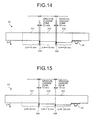
- the cross-sectional shape determination device 29 set, as illustrated in FIG. 14 , the displacement ⁇ H of the cross-sectional height H 3 of the segment 333 to the highest possible value (20 mm, for example).
- the cross-sectional shape determination device 29 set the displacement ⁇ H of the cross-sectional height H 1 of the segment 331 to 0 mm for preventing the increase in weight of the rear side member 33.
- the cross-sectional shape determination device 29 also increases the displacement ⁇ H of the cross-sectional height H 2 of the segment 332.
- the cross-sectional shape determination device 29 set the displacement ⁇ H of the cross-sectional height H 2 of the segment 332 to a value (10 mm, for example) shorter than the cross-sectional height H 3 of the segment 333 and higher than the cross-sectional height H 1 of the segment 331.
- the shape of the boundary portion of the segment 331, 332, or 333 was set to a shape that gradually changes appropriately by using the editor function of the cross-sectional shape determination device 29. To be more specific, as illustrated in FIG.
- the cross-sectional shape determination device 29 set each of the gradual change zone 334 and 335 to a zone with a length (20 mm, for example) extending over the boundary portion of each of the segment 331, 332, and 333.
- the improvement rate of rigidity of the automotive body 31 in the shape of the rear side member 33 illustrated in FIG. 14 was +3.4%.
- the cross-sectional shape determination device 29 provided, as illustrated in FIG. 14 , the gradual change zones 334 and 335 in such a manner that each of the gradual change zones extends over the boundary portion of the segments 331, 332, or 333.
- the cross-sectional shape determination device 29 providing the gradual change zones 334 and 335 such that the cross-sectional height of the segment of the part having high contribution to the rigidity of the automotive body 31 is maintained as high as possible, the rigidity of the automotive body 31 is able to be increased further.
- the cross-sectional shape determination device 29 changed the gradual change zones 334 and 335 of the rear side member 33 having the shape illustrated in FIG. 14 as follows.
- the cross-sectional shape determination device 29 shrunk the gradual change zones 334 and 335 and set, for example, the length of each zone to 10 mm. Furthermore, the cross-sectional shape determination device 29 did not provide each of the gradual change zones 334 and 335 on the side of a part with large contribution to the rigidity of the automotive body 31, but provided each zone only on the side of a part with small contribution to the rigidity of the automotive body 31.
- the improvement rate of rigidity of the automotive body 31 in the shape of the rear side member 33 illustrated in FIG. 15 was +4.2%.
- the weight of the rear side member 33 increases by 257 g. Accordingly, the improvement rate of rigidity per 1 g of the increase in weight of the automotive body 31 in optimizing the shape of the part illustrated in FIG. 15 was 0.016%/g.
- FIG. 16 illustrates a bar graph of results indicating high improvement rate of rigidity that are extracted from the results of analyses in the present example 1.
- a horizontal axis indicates an examined shape
- a vertical axis indicates an improvement rate of rigidity.
- a black bar illustrated on the rightmost side in FIG. 16 indicates the improvement rate of rigidity in the shape illustrated in FIG. 15 .
- Each of the other bars indicates the improvement rate of rigidity obtained as a result of performing rigidity analyses while maintaining the part shape obtained by the part shape pattern setting device 21 without gradually changing a boundary portion between segments of a part.
- the improvement rate of rigidity in the present example 1 was 4.2%.
- the improvement rate of rigidity in the present example 1 became more preferable. Therefore, by using the optimization analyzing apparatus 1 according to the present example, the maximum value of rigidity was obtained reliably even when rigidity analyses with respect to all of 360 kinds of rigidity analysis patterns were not performed.
- a part of a structural body to be analyzed in the present example 2 was, in the same manner as the case of the above-mentioned example 1, the rear side member 33 illustrated in FIG. 3 . Furthermore, in the present example 2, the rear side member 33 was, in the same manner as the case of the above-mentioned example 1, divided into the segments 331, 332, and 333.
- the level or the like of the variable ⁇ H of each of the cross-sectional heights H 1 , H 2 , and H 3 of the segments was same as the case of the above-mentioned embodiment or example 1.
- the constitution in the present example 2 is same as the case of the above-mentioned embodiment or example 1 except that the rigidity or the improvement rate of rigidity is substituted with the improvement rate of rigidity per increased unit weight.
- Results of performing multivariate analyses in the present example 2 are listed in Table 2.
- Table 2 lists, in the same manner as the case of the above-mentioned Table 1, adjusted R-squares and regression coefficients (standard partial regression coefficients and multiple regression coefficients) of the above-mentioned ten (10) kinds of rigidity analyses.
- the manner of understanding the entire contents listed in Table 2 is same as the case of Table 1 and hence, the explanations thereof are omitted.
- FIG. 17 a graph of the multiple regression coefficients listed in Table 2 for every analysis condition and for every load condition is illustrated.
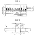
- FIG. 18 a graph of the standard partial regression coefficients listed in Table 2 for every analysis condition and for every load condition is illustrated.
- each of the cross-sectional heights H 2 and H 3 of the segments 332 and 333 largely contributes to the torsional rigidity of the predetermined portion 511 or the predetermined portion 512 of the automotive body 31 illustrated in FIG. 7 ; that is, the shock absorber mount, and the local rigidity of the coiled spring leg (the predetermined portion 516 illustrated in FIG. 8 ).
- the multiple regression coefficient of the segment 333 exhibits an extremely high value.
- a degree of contribution of the cross-sectional height H 1 , H 2 , or H 3 of the segment 331, 332, or 333 to the rigidity of the automotive body 31 can be found.
- the segment 333 is effective for the reinforcement of all of the predetermined portions 511, 512, 513, and 514 (see FIG. 7 ) of the automotive body 31.
- rigidity values of the predetermined portion 513 and the predetermined portion 514 are preferentially increased, it can be found that the reinforcement of the segment 331 is effective therefor.
- results of analyses in the above-mentioned example 1 and Table 2 in the present example 2 are compared with each other.
- the ratio of an average value of the multiple regression coefficients of the segment 332 (except the multiple regression coefficient of the shock absorber mount) to an average value of the multiple regression coefficients of the segment 333 (except the multiple regression coefficient of the shock absorber mount) was 0.45.
- the ratio mentioned above was 0.30.
- the shape of the rear side member 33 was determined as follows.
- the cross-sectional shape determination device 29 set, as illustrated in FIG. 19 , the displacement ⁇ H of the cross-sectional height H 3 of the segment 333 to 20 mm that is a maximum value thereof.
- the displacement ⁇ H of the cross-sectional height H 1 of the segment 331 was set to 0 mm for preventing the increase in weight of the rear side member 33.
- the cross-sectional shape determination device 29 set the displacement ⁇ H of the cross-sectional height H 2 of the segment 332 to 5 mm that is a level lower than the case of the example 1 (10 mm).
- the cross-sectional shape determination device 29 provided, as illustrated in FIG.
- the gradual change zones 334 and 335 each of which has a length (20 mm, for example) extending over the boundary portion of the segment 331, 332, or 333.
- a shape such that the shape of the rear side member 33 illustrated in FIG. 19 is further optimized based on the contribution of the segment 331, 332, or 333 to the rigidity of the automotive body 31 is illustrated in FIG. 20 . As illustrated in FIG.
- the cross-sectional shape determination device 29 did not provide, in the boundary portion between the segment 333 and the segment 332, the gradual change zone 335 on the side of the segment 333 with relatively large contribution to the rigidity of the automotive body 31 but provided the gradual change zone 335 (whose length is 10 mm) on the side of the segment 332 with relatively small contribution to the rigidity of the automotive body 31.
- the cross-sectional shape determination device 29 did not provide, in the boundary portion between the segment 332 and the segment 331, the gradual change zone 334 on the side of the segment 332 with relatively large contribution to the rigidity of the automotive body 31 but provided the gradual change zone 334 (whose length is 10 mm) on the side of the segment 331 with relatively small contribution to the rigidity of the automotive body 31.
- the cross-sectional shape determination device 29 further optimized the shape of the rear side member 33.
- the cross-sectional height of each segment of a structural part was changed so as to set the part shape pattern of the structural part; however, the present invention is not limited to these cases.
- the part shape pattern setting device in the present invention may change the width (transverse-sectional width, for example) of each segment of a structural part so as to set the part shape pattern of the structural part.
- the cross-sectional height of each segment of a structural part was set as an explanatory variable and any of the rigidity of the structural body, the improvement rate of rigidity, or the improvement rate of rigidity per increased unit weight was set as a response variable to perform a multivariate analysis; however, the present invention is not limited to these cases.
- the multivariate analyzing device in the above-mentioned embodiment and examples 1 and 2 may set the width (transverse-sectional width, for example) of each segment of the structural part or a modulus of section as an explanatory variable to perform the above-mentioned multivariate analysis.
- the cases are exemplified that a rigidity analysis in high correlation is selected from plural kinds of rigidity analyses based on an adjusted R-square calculated by the multivariate analyzing device; however, the present invention is not limited to these cases.
- the rigidity analysis selection device in the present invention may select the rigidity analysis in high correlation from plural kinds of rigidity analyses based on a coefficient of determination calculated by the multivariate analyzing device.
- the torsional rigidity and the local rigidity were exemplified; however, the present invention is not limited to these cases.
- the rigidity of the structural body analyzed in the present invention may be other than the torsional rigidity or the local rigidity, and no restriction on the kind of rigidity is imposed in particular.
- the cases of ten (10) kinds of rigidity analyses was exemplified; however, the present invention is not limited to these cases.
- the number of kinds of rigidity analyses performed by the rigidity analyzing device in the present invention may be any as long as it is plural.
- a structural part is divided into three in the longitudinal direction thereof; however, the present invention is not limited to these cases.
- no restriction on the number of division and the direction of division of the structural part are imposed in particular.
- the number of division and the direction of division that are preferable to the rigidity analysis of the structural body may be set.
- an automotive body as an example of the structural body is exemplified; however, the present invention is not limited to these cases.
- the optimization analyzing apparatus according to the present invention may perform the rigidity analysis of the structural body other than the automotive body so as to optimize the shape of a part of which a structural body is constituted.
- a rear side member as an example of a structural part is exemplified; however, the present invention is not limited to these cases.
- the optimization analyzing apparatus in the present invention may optimize the shape of a part other than the rear side member so as to improve the rigidity of an automotive body or a structural body other than the automotive body.
- the displacement of the cross-sectional height of each of portions into which the structural part is divided is changed in three levels of 0 mm, 10 mm, and 20 mm or four levels of 0 mm, 10 mm, 20 mm, and 30 mm; however, the present invention is not limited to these cases.
- the displacement of the cross-sectional height of each portion may be set to a desired quantity based on the constitution or the arrangement of the structural part.
- the present invention is not limited to the above-mentioned embodiment or examples 1 and 2.
- the present invention includes a case of constituting the above-mentioned constitutional features arbitrarily by combining with each other.
- the present invention includes all of the other embodiments, examples, applications, or the like made by those who are skilled in the art or the like based on the above-mentioned embodiment.
- the optimization analyzing apparatus for a shape of a structural part is useful for analyzing a part shape of a structural body, and more particularly for accurately optimizing the part shape of the structural body.
Landscapes
- Engineering & Computer Science (AREA)
- Physics & Mathematics (AREA)
- Geometry (AREA)
- Theoretical Computer Science (AREA)
- General Physics & Mathematics (AREA)
- Computer Hardware Design (AREA)
- Evolutionary Computation (AREA)
- General Engineering & Computer Science (AREA)
- Mathematical Optimization (AREA)
- Mathematical Analysis (AREA)
- Computational Mathematics (AREA)
- Pure & Applied Mathematics (AREA)
- Automation & Control Theory (AREA)
- Aviation & Aerospace Engineering (AREA)
- Vehicle Body Suspensions (AREA)
- Architecture (AREA)
- Software Systems (AREA)
- Investigating Strength Of Materials By Application Of Mechanical Stress (AREA)
- Body Structure For Vehicles (AREA)
- Management, Administration, Business Operations System, And Electronic Commerce (AREA)
Abstract
Description
- The present invention relates to an optimization analyzing apparatus for a shape of a part of a structural body, which optimizes a shape of a part (hereinafter, also referred to as "structural part") that forms a structural body such as an automotive body, for example.
- Conventionally, in many industries, weight reduction of structural bodies has been promoted. Particularly in the automotive industry, weight reduction of automotive bodies due to environmental issues has been promoted recently. In designing such an automotive body, an analysis using computer-aided engineering (hereinafter, referred to as "CAE analysis") has been an indispensable technique.
- The CAE analysis has been known as an analytical technique capable of improving rigidity of a structural body or achieving the weight reduction of an automotive body by using an optimization technique such as mathematical optimizers, a plate thickness optimization method, a shape optimization method, or a topology optimization method (see, for example, Patent Document 1). As a shape optimization method from among the above-mentioned optimization techniques, an optimization method that equally changes a shape of a structural part by using a representative dimension of the structural part has been used generally.
- Patent Literature 1: Japanese Laid-open Patent Application No.
2006-330917 - The conventionally performed shape optimization method for a part of a structural body is a method of performing analysis by changing a shape of the entire part. Hence, it is impossible to obtain accurate results from this analysis. Therefore, the conventional shape optimization methods have been insufficient as optimization methods of a shape of a part. Furthermore, when a rigidity analysis is performed in optimizing a shape of a part, a method of analyzing by determining load and constraint conditions suitable to the part alone has been conventionally general. Hence, load transfer or the like when that part is incorporated in a structural body such as an automotive body is not reproduced correctly. Therefore, the shape optimization methods of structural parts have been insufficient.
- The present invention has been made in order to solve the above problem and its object is to obtain an optimization analyzing apparatus for a shape of a structural part, which uses a multivariate analysis and is able to accurately optimize a shape of a part of a structural body.
- To solve the above-described problem and achieve the object, an optimization analyzing apparatus for a shape of a part of a structural body according to the present invention is configured of a computer and includes: a part shape pattern setting device that divides a part of a structural body including a two-dimensional element and/or a three-dimensional element into a plurality of segments in an axis direction, changes a height or width of a cross section of each of the segments divided, and sets a part shape pattern; a rigidity analyzing device that performs plural kinds of rigidity analyses of the structural body in a state in which the part for which the part shape pattern has been set by the part shape pattern setting device is incorporated in the structural body and obtains any of: rigidity; improvement rate of rigidity; and improvement rate of rigidity per increased unit weight, of the structural body for each kind of the rigidity analyses; a multivariate analyzing device that performs a multivariate analysis for each kind of the rigidity analyses where any of the rigidity, the improvement rate of rigidity, and the improvement rate of rigidity per increased unit weight of the structural body that have been obtained by the rigidity analyzing device is a response variable and any of the height, the width, and a section modulus of each of the segments divided is an explanatory variable, and obtains a multiple regression coefficient, and a coefficient of determination or an adjusted R-square; a rigidity analysis selection device that selects, based on any of the coefficient of determination and the adjusted R-square, any having strong correlation from among the rigidity analyses of the plural kinds; and a cross-sectional shape determination device that determines, based on the multiple regression coefficient calculated by the multivariate analyzing device in a rigidity analysis selected by the rigidity analysis selection device, a cross-sectional shape of each of the segments divided.
- An optimization analyzing apparatus for a shape of a part of a structural body according to the present invention is characterized in that, in the above-mentioned invention, the multivariate analyzing device calculates a standard partial regression coefficient, and the optimization analyzing apparatus further comprises a shape change priority determination device that determines, based on the standard partial regression coefficient, a priority of change in shape of each segment for each of the plural kinds of rigidity analyses.
- An optimization analyzing apparatus for s shape of s part of s structural body according to the present invention is characterized in that in the above-mentioned invention, the cross-sectional shape determination device determines a shape of a boundary portion of each of the segments divided or a shape in the vicinity of the boundary portion to be a gradually changing shape.
- The present invention realizes an advantageous effect such that optimization for a shape of a structural part can be accurately performed.
-
-
FIG. 1 is a block diagram illustrating an example of the constitution of an optimization analyzing apparatus for a shape of a structural part according to one embodiment of the present invention. -
FIG. 2 is an explanatory view for explaining an example of a structural body. -
FIG. 3 is an explanatory view for explaining a part of the structural body illustrated inFIG. 2 . -
FIG. 4 is a cross-sectional view taken along a line X-X with respect to a part illustrated inFIG. 3 as viewed in the direction indicated by arrows. -
FIG. 5A is an explanatory view for explaining a method for setting a shape of the part illustrated inFIG. 3 . -
FIG. 5B is an explanatory view for explaining an example of cross-sectional height variation of the part illustrated inFIG. 3 . -
FIG. 5C is an explanatory view for explaining another example of cross-sectional height variation of the part illustrated inFIG. 3 . -
FIG. 6 is an explanatory view for explaining one aspect of the shape of the part illustrated inFIG. 3 . -
FIG. 7 is an explanatory view for explaining an example of load and constraint conditions as an analysis condition. -
FIG. 8 is an explanatory view for explaining another example of load and constraint conditions as an analysis condition. -
FIG. 9 is an explanatory view for explaining an example of results of multivariate analyses. -
FIG. 10 is an explanatory view for explaining another example of results of multivariate analyses. -
FIG. 11 is an explanatory view for explaining yet another example of results of multivariate analyses. -
FIG. 12 is an explanatory view for explaining an example of an optimized shape of the part illustrated inFIG. 3 . -
FIG. 13A is an explanatory view for explaining an example of a shape obtained by further shape optimization of the part illustrated inFIG. 12 . -
FIG. 13B is an explanatory view for explaining another example of a shape obtained by further shape optimization of the part illustrated inFIG. 12 . -
FIG. 14 is an explanatory view for explaining an example of an optimized shape of a part in an example 1. -
FIG. 15 is an explanatory view for explaining an example of a shape obtained by further shape optimization of the part illustrated inFIG. 14 . -
FIG. 16 is an explanatory view for explaining an advantageous effect of the example 1. -
FIG. 17 is an explanatory view for explaining an example of results of multivariate analyses in an example 2. -
FIG. 18 is an explanatory view for explaining another example of results of multivariate analyses in the example 2. -
FIG. 19 is an explanatory view for explaining an example of an optimized shape of a part in the example 2. -
FIG. 20 is an explanatory view for explaining an example of a shape obtained by further shape optimization of the part illustrated inFIG. 19 . - Hereinafter, preferred embodiments of an optimization analyzing apparatus for a shape of a structural part (hereinafter, simply referred to as "optimization analyzing apparatus") according to the present invention are explained in detail referring to drawings.
- An
optimization analyzing apparatus 1 according to the present embodiment, theoptimization analyzing apparatus 1 being illustrated inFIG. 1 is an apparatus for performing optimized calculation by numerical analysis with respect to a shape of a part of a structural body constituted with two-dimensional elements and/or three-dimensional elements. The structural body in the present embodiment includes, as an example, anautomotive body 31 illustrated inFIG. 2 . The part that constitutes the structural body in the present embodiment includes, as an example, arear side member 33 illustrated inFIG. 3 or the like. Furthermore, in the present embodiment, as illustrated inFIG. 2 , the width direction of theautomotive body 31 is referred to as a BL direction, the height direction of theautomotive body 31 is referred to as a WL direction, and the longitudinal direction of theautomotive body 31 is referred to as a TL direction. First of all, therear side member 33 is explained below. - The
rear side member 33 is, as illustrated in an area surrounded by an ellipse inFIG. 2 , a part that constitutes a rearward lower portion of theautomotive body 31. Only therear side member 33 separated from theautomotive body 31 is illustrated inFIG. 3 . Therear side member 33 is, as illustrated inFIG. 3 and FIG. 4 , a long strip-shaped hat cross-sectional part. Therear side member 33 has, as illustrated inFIG. 3 , a coiledspring leg 35. The coiledspring leg 35 supports a coiled spring mounted on a lower surface in the vicinity of one end portion of therear side member 33. Therear side member 33 is, as illustrated inFIG. 2 , attached to theautomotive body 31 in a manner extending thecoiled spring leg 35 toward the lower side of theautomotive body 31. Hereinafter, theoptimization analyzing apparatus 1 for obtaining the optimized shape of therear side member 33 is explained referring toFIG. 1 . - The
optimization analyzing apparatus 1 is constituted of a personal computer (PC) and has, as illustrated inFIG. 1 , adisplay device 3, aninput device 5, amemory storage 7, a workingdata memory 9, and an arithmetic processing unit 11. Furthermore, the arithmetic processing unit 11 connects thereto thedisplay device 3, theinput device 5, thememory storage 7, and the workingdata memory 9. Thedisplay device 3, theinput device 5, thememory storage 7, and the workingdata memory 9 respectively perform functions in response to instructions of the arithmetic processing unit 11. - The
display device 3 displays thereon various kinds of information such as input information by theinput device 5 and results of calculating by the arithmetic processing unit 11. Thedisplay device 3 is constituted by using a liquid crystal display (LCD) monitor or the like. - The
input device 5 inputs, in response to input operations by an operator, various kinds of information such as instruction information for instructing the display of astructural body file 13 in thememory storage 7 and analysis conditions. Theinput device 5 is constituted by using a keyboard, a mouse, or the like. - The
memory storage 7 stores therein at least various kinds of information such as thestructural body file 13. Thestructural body file 13 is information indicative of types, combinations, or the like of respective elements that constitute a structural body. The structural body may be constituted only of two-dimensional elements or only of three-dimensional elements, or may be constituted of two-dimensional elements and three-dimensional elements that are combined with each other. For example, theautomotive body 31 designated as an example of the structural body is, as illustrated inFIG. 2 , mainly formed by steel sheet. That is, theautomotive body 31 is mainly constituted of two-dimensional elements. Furthermore, among respective elements that constitute theautomotive body 31, a block body or the like may be formed of three-dimensional elements. - The working
data memory 9 has adata storage area 15 for storing calculation results and a workingarea 17 for performing arithmetic processing. - The arithmetic processing unit 11 is constituted of a central processing unit (CPU) of the PC. Each device in the arithmetic processing unit 11 explained below is realized by predetermined programs executed by the CPU.
- In the present embodiment, the arithmetic processing unit 11 realizes a part shape pattern setting device 21 that divides a part of a structural body constituted of two-dimensional elements and/or three-dimensional elements into a plurality of portions in one axis direction and changes cross-sectional heights or widths with respect to the respective portions divided to set a part shape pattern, a rigidity analyzing device 23 that performs plural kinds of rigidity analyses for the structural body in a state that the part to which the part shape pattern is set by the part shape pattern setting device 21 is incorporated in the structural body to obtain any of the rigidity, improvement rate of rigidity, and improvement rate of rigidity per increased unit weight of the structural body for each kind of the above-mentioned rigidity analyses, a multivariate analyzing device 25 that sets any of the rigidity, improvement rate of rigidity, and improvement rate of rigidity per increased unit weight of the structural body that are obtained by the rigidity analyzing device 23 as a response variable, sets any of the height, width, and section modulus of the above-mentioned each portion divided as an explanatory variable, performs a multivariate analysis for each kind of the rigidity analyses to obtain a multiple regression coefficient, and a coefficient of determination or an adjusted R-square, a rigidity analysis selection device 27 that selects any having strong correlation from among the rigidity analyses of the plural kinds based on any of the above-mentioned coefficient of determination and adjusted R-square, and a cross-sectional shape determination device 29 that determines the cross-sectional shape of the above-mentioned each portion divided based on the above-mentioned multiple regression coefficient calculated by the above-mentioned multivariate analyzing device 25 in the rigidity analysis selected by the rigidity analysis selection device 27. Hereinafter, the respective devices are explained in detail referring to
FIG. 1 to FIG. 13 . - The part shape pattern setting device 21 divides a part of a structural body constituted of two-dimensional elements and/or three-dimensional elements into a plurality of portions in one axis direction, changes a cross-sectional height or width with respect to each portion divided to set a part shape pattern. In the present embodiment, as an example, the part shape pattern setting device 21 divides the
rear side member 33 illustrated inFIG. 3 intosegments segments rear side member 33 is divided in the TL direction. The part shape pattern setting device 21 changes the cross-sectional heights of therespective segments rear side member 33. - The
rear side member 33 is, as illustrated inFIG. 4 , the hat cross-sectional part havingvertical wall portions 37 and atop plate portion 39. In the present embodiment, the change in cross-sectional height mentioned above means that the lengths of thevertical wall portions 37 in at least one of therespective segments rear side member 33 are changed to change a distance from a standard shape of therear side member 33 to thetop plate portion 39. In such a change in cross-sectional height, the standard shape of therear side member 33 is, as an example illustrated inFIG. 3 , a shape such that the outer surface of thetop plate portion 39 is flat in the longitudinal direction of the rear side member 33 (in the TL direction of theautomotive body 31 illustrated inFIG. 2 ). A displacement ΔH illustrated inFIGS. 5B and 5C is a displacement of the distance from the standard shape of therear side member 33 to thetop plate portion 39; that is, a displacement of the cross-sectional height from the standard shape of therear side member 33. InFIGS. 5B and 5C , the standard shapes of therear side member 33 are illustrated by solid lines. - In the present embodiment, the part shape pattern setting device 21 changes, for example, as illustrated in
FIG. 5B , the displacement ΔH of each cross-sectional height of thesegments FIG. 5C , the displacement ΔH of the cross-sectional height of thesegment 332 to any of four displacements (0 mm, 10 mm, 20 mm, and 30 mm). Accordingly, there exist in total 36 (=3x4x3) combinations of the shapes of thesegments rear side member 33. As an example of the part shape pattern, when the part shape pattern setting device 21 sets the displacement of the cross-sectional height of thesegment 331 to 10 mm, sets the displacement of the cross-sectional height of thesegment 332 to 0 mm, and sets the displacement of the cross-sectional height of thesegment 333 to 20 mm, therear side member 33 forms a shape illustrated inFIG. 6 in accordance with the setting of the displacements ΔH of these cross-sectional heights. In such a setting of the part shape pattern, the shape of the segment whose displacement ΔH is 0 mm among thesegments rear side member 33. - The rigidity analyzing device 23 performs plural kinds of rigidity analyses of the structural body in a state that the part to which the part shape pattern is set by the part shape pattern setting device 21 is incorporated in the structural body to be analyzed to obtain any of the rigidity, improvement rate of rigidity, and improvement rate of rigidity per increased unit weight of the structural body for each kind of the rigidity analyses. As the kinds of a plurality of rigidity analyses performed by the rigidity analyzing device 23, for example, torsional rigidity of the
automotive body 31, local rigidity at a place to which a part is attached, or the like is designated. Each of these plural kinds of rigidity analyses is further subdivided for each load and constraint condition. - In the present embodiment, the rigidity is a value obtained as a result of the rigidity analysis performed by the rigidity analyzing device 23. The improvement rate of rigidity is an index indicating the degree of improvement of the rigidity of a structural body after setting a part shape pattern in comparison with a structural body having a standard shape. The improvement rate of rigidity is, for example, useful to find the degree of improvement of the rigidity of a structural body after setting a part shape pattern in comparison with a structural body having a standard shape; that is, the tendency of improvement thereof. The improvement rate of rigidity per increased unit weight is an index indicating the degree of improvement of the rigidity rate per increased unit weight of a structural body. The improvement rate of rigidity per increased unit weight is calculated by dividing the above-mentioned improvement rate of rigidity by an increased weight of a structural body or a part thereof. The improvement rate of rigidity per increased unit weight is useful to obtain an optimized shape of a part in consideration of the weight of the structural body.
- The rigidity analyzing device 23 in the present embodiment performed the torsional rigidity analysis and the local rigidity analysis as examples of the plural kinds of rigidity analyses. In the tosional rigidity analysis, the rigidity analyzing device 23 incorporates, as illustrated in
FIG. 7 , therear side member 33 in theautomotive body 31. Subsequently, the rigidity analyzing device 23 constrains three portions amongpredetermined portions automotive body 31 and, at the same time, applies a predetermined load (an upward load of 0.5 kN, for example) to the other one portion as illustrated by arrows inFIG. 7 . In the present embodiment, thepredetermined portions automotive body 31 are, for example, as illustrated inFIG. 7 , portions each of which is a portion of a shock absorber mount for mounting a shock absorber thereon. On the other hand, thepredetermined portions FIG. 7 , portions each of which is a portion of the above-mentionedcoiled spring leg 35. The rigidity analyzing device 23 obtained, as described above, the torsional rigidity of theautomotive body 31 by analyzing in applying the upward load to theautomotive body 31. The rigidity analyzing device 23 sequentially changes a portion for applying the upward load in theautomotive body 31 to any of thepredetermined portions - In the local rigidity analysis, the rigidity analyzing device 23 incorporates, as illustrated in
FIG. 8 , therear side member 33 of theautomotive body 31. Subsequently, the rigidity analyzing device 23 constrains, as illustrated inFIG. 8 , a predetermined portion of theautomotive body 31 such as a portion in the vicinity of a connection portion between the lower portion of aB pillar 41 located at the middle of theautomotive body 31 and a side member 43 (a portion indicated by a black square inFIG. 8 ). The rigidity analyzing device 23 applies, while maintaining a constrained state of theautomotive body 31, a load to apredetermined portion 515 or apredetermined portion 516 of theautomotive body 31 in one direction chosen among the BL direction, the WL direction, and the TL direction as illustrated by arrows inFIG. 8 . In the present embodiment, thepredetermined portion 515 of theautomotive body 31 is, as illustrated inFIG. 8 , a portion such as the above-mentioned shock absorber mount. On the other hand, thepredetermined portion 516 of theautomotive body 31 is, as illustrated inFIG. 8 , a portion such as the above-mentionedcoiled spring leg 35. Thepredetermined portion automotive body 31 has a bilaterally symmetrical shape, one of both-side shock absorber mounts or one of both-side coiledspring legs 35. The rigidity analyzing device 23 obtained, by applying a load to theautomotive body 31 as described above, the displacement of the portion to which the load is applied in theautomotive body 31 by the analysis. The rigidity analyzing device 23 sequentially changes a portion to which the load is applied in theautomotive body 31 to any of the remainingpredetermined portions - As mentioned above, in the present embodiment, the number of the load conditions of the torsional rigidity analyses by the rigidity analyzing device 23 is four (4). Furthermore, the number of the load conditions of the local rigidity analyses by the rigidity analyzing device 23 is six (6). Accordingly, the number of the kinds of the rigidity analyses performed by the rigidity analyzing device 23 is ten (10).
- Furthermore, as described above, the number of the part shape pattern of the
rear side member 33 that is set by the part shape pattern setting device 21 is 36. The rigidity analyzing device 23 performs analyses for each of the 36 part shape patterns in accordance with the load conditions in the respective kinds of the above-mentioned total ten (10) rigidity analyses. Accordingly, there exist 360 (= 36 x 10) kinds of rigidity analysis patterns by the rigidity analyzing device 23. In the present embodiment, the rigidity analyzing device 23 reduced the 360 kinds of rigidity analysis patterns to half based on an experimental design and analyzed 180 kinds of rigidity analysis patterns. An ordinary rigidity analysis requires calculations of all of the rigidity analysis patterns. However, theoptimization analyzing apparatus 1 according to the present invention uses the multivariate analysis method, and can obtain reliable rigidity analysis results even when the number of the rigidity analysis pattern is reduced to half as described above. - The
multivariate analyzing device 25 sets any of the rigidity, improvement rate of rigidity, and improvement rate of rigidity per increased unit weight of a structural body that are obtained by the rigidity analyzing device 23 as a response variable, sets any of the height, width, and section modulus of each of portions into which the structural body is divided as an explanatory variable, and performs a multivariate analysis for each kind of rigidity analyses performed by the rigidity analyzing device 23 to obtain a multiple regression coefficient, and a coefficient of determination or an adjusted R-square. The multivariate analysis is a statistical analysis method for finding regularity by analyzing objective phenomena. In the present invention, the multivariate analyses are performed so as to find the degree of effect of the height, width, or section modulus of each of portions into which the structural body is divided on the rigidity, improvement rate of rigidity, or improvement rate of rigidity per increased unit weight of the structural body numerically and reliably. - The multivariate analysis performed by the
multivariate analyzing device 25 is specifically progressed in accordance with the following procedures. First of all, a relational expression for the multivariate analysis is made. Next, themultivariate analyzing device 25 obtains a multiple regression coefficient as a regression coefficient of the relational expression. Themultivariate analyzing device 25 may obtain a standard partial regression coefficient other than the multiple regression coefficient as such a regression coefficient. Furthermore, themultivariate analyzing device 25 obtains a coefficient of determination that is an index indicating the degree of being able to explain a response variable by the relational expression or an adjusted R-square (R2) in which the degree of freedom of the coefficient of determination is adjusted. - In the present embodiment, the
multivariate analyzing device 25 sets the result of performing rigidity analyses with respect to the above-mentioned 180 rigidity analysis patterns; that is, the rigidity of theautomotive body 31 as a response variable. Furthermore, themultivariate analyzing device 25 sets the cross-sectional height of eachsegment rear side member 33 is divided as an explanatory variable. Themultivariate analyzing device 25 creates an expression (1) as a relational expression for explaining the above-mentioned response variable with the use of the explanatory variable. Themultivariate analyzing device 25 performed multivariate analyses based on the expression (1). In the expression (1), each regression coefficient α, β, or γ is a multiple regression coefficient or a standard partial regression coefficient. A cross-sectional height H1 is the cross-sectional height of thesegment 331 of therear side member 33. A cross-sectional height H2 is the cross-sectional height of thesegment 332 of therear side member 33. A cross-sectional height H3 is the cross-sectional height of thesegment 333 of therear side member 33.
- The
multivariate analyzing device 25 performed the multivariate analyses of the above-mentioned 180 rigidity analysis patterns based on the expression (1). Results of the multivariate analyses are listed in Table 1. Hereinafter, results of discussion with respect to Table 1 are explained.Table 1 Torsional rigidity Local rigidity Shock absorber mount Coiled spring leg a 511 b 512 c 513 d 514BL TL WL BL TL WL Adjusted R-square (R2) 0.95 0.96 0.92 0.93 0.35 0.45 0.51 0.81 0.87 0.94 Standard partial regression coefficient Cross-sectional height H1 0.22 0.21 0.44 0.43 -0.21 0.10 0.21 -0.31 0.06 0.05 Cross-sectional height H2 0.35 0.36 0.33 0.32 0.51 0.46 0.40 0.30 0.11 0.15 Cross-sectional height H3 0.51 0.50 0.25 0.25 0.30 0.44 0.38 0.31 0.93 0.88 Multiple regression coefficient Cross-sectional height H1 0.10 0.11 0.05 0.06 -0.01 0.01 0.01 -0.05 0.05 0.02 Cross-sectional height H2 0.31 0.34 0.04 0.03 0.06 0.04 0.07 0.13 0.15 0.29 Cross-sectional height H3 0.59 0.55 0.01 0.01 0.02 0.01 0.03 0.25 0.87 0.61 - Table 1 lists adjusted R-squares and regression coefficients (standard partial regression coefficients and multiple regression coefficients) for all kinds of 10 rigidity analyses performed in the above-mentioned rigidity analyzing device 23. In Table 1, the adjusted R-squares and the regression coefficients are separately described in the respective rows for every rigidity analysis condition and every load condition.
- To be more specific, in Table 1, "a", "b", "c", or "d" described in the column of "Torsional rigidity" indicates a load condition in analyzing the torsional rigidity of the
automotive body 31 illustrated inFIG. 7 . The "a" indicates that a load-applied portion of theautomotive body 31 is thepredetermined portion 511. The "b" indicates that a load-applied portion of theautomotive body 31 is thepredetermined portion 512. The "c" indicates that a load-applied portion of theautomotive body 31 is thepredetermined portion 513. The "d" indicates that a load-applied portion of theautomotive body 31 is thepredetermined portion 514. For example, in the row of "a" of the "Torsional rigidity", the adjusted R-squares and the regression coefficients are shown when the torsional rigidity analysis is performed under the load condition that a load is applied to thepredetermined portion 511 of theautomotive body 31 and the otherpredetermined portions - In Table 1, "Shock absorber mount", "Coiled spring leg", "BL", "TL", and "WL" of the column of "Local rigidity" indicate load conditions in analyzing the local rigidity of the
automotive body 31 illustrated inFIG. 8 . The "Shock absorber mount" indicates that the load-applied portion of theautomotive body 31 is a portion of the shock absorber mount (thepredetermined portion 515 illustrated inFIG. 8 ). The "Coiled spring leg" indicates that the load-applied portion of theautomotive body 31 is a portion of the coiled spring leg 35 (thepredetermined portion 516 illustrated inFIG. 8 ). The "BL" indicates that a direction in which a load is applied to theautomotive body 31 is the BL direction (the width direction of the automotive body 31). The "TL" indicates that a direction in which a load is applied to theautomotive body 31 is the TL direction (the longitudinal direction of the automotive body 31). The "WL" indicates that a direction in which a load is applied to theautomotive body 31 is the WL direction (the height direction of the automotive body 31). For example, in the row of "BL" of the "Shock absorber mount" of the "Local rigidity", adjusted R-squares and regression coefficients are shown when the local rigidity analysis is performed under the load condition that a load in the BL direction is applied to the predetermined portion 515 (the shock absorber mount) of theautomotive body 31 illustrated inFIG. 8 . Furthermore, as a load condition in analyzing the local rigidity, a portion in the vicinity of the joined portion between the lower portion of theB pillar 41 located in the middle of theautomotive body 31 and aside member 43 is constrained. - In the uppermost line of numerical value columns in Table 1, the adjusted R-squares are listed. In lines below the uppermost line, the standard partial regression coefficients and the multiple regression coefficients are described. The adjusted R-square is, in a multiple regression analysis, used for adjusting the degree of freedom of regression to prevent the tendency of a regression result to be improved by increasing the number of the explanatory variables.
- The manner of understanding the entire contents described in Table 1 is explained. For example, when viewing the row of the "a" of the "Torsional rigidity" in Table 1, with respect to the rigidity as a result of analyzing the torsional rigidity under the load condition corresponding to the "a", the standard partial regression coefficient, the multiple regression coefficient described in the expression (1), and the adjusted R-square can be read. That is, in analyzing the torsional rigidity under the load condition corresponding to the "a", the rigidity analyzing device 23 performs the torsional rigidity analysis under the load condition that a load is applied to the predetermined portion 511 (see
FIG. 7 ) of theautomotive body 31 and the otherpredetermined portions automotive body 31 is obtained. As the regression coefficients α, β, and γ in the expression (1) and the adjusted R-square indicating correlation between the rigidity of theautomotive body 31 and the cross-sectional heights H1, H2, and H3 of therear side member 33, values in the row of the "a" can be read. For example, when the multiple regression coefficient described in the row of the "a" is used as the regression coefficient α, β, or γ in the expression (1), a relational expression indicating correlation between the rigidity of theautomotive body 31 and the cross-sectional heights H1, H2, and H3 of therear side member 33 is expressed as an expression (2). In this case, the adjusted R-square is 0.95.
- The multiple regression coefficient is, in the present embodiment, an index indicating a contribution to a rigidity. The multiple regression coefficient is an absolute index, the absolute indexes being capable of being compared with each other through whole analysis conditions. When the multiple regression coefficient is investigated, the degree of contribution of the cross-sectional height H1, H2, or H3 of each
segment rear side member 33 to the rigidity of theautomotive body 31 through each analysis condition can be found. -
FIG. 9 is a plot of the multiple regression coefficients listed in Table 1 for every analysis condition and for every load condition. InFIG. 9 , a bar graph with hatched lines corresponds to thesegment 331 of therear side member 33; a black bar corresponds to thesegment 332 of therear side member 33; and a white bar corresponds to thesegment 333 of therear side member 33. When referring toFIG. 9 , it can be found that the cross-sectional height H1 of thesegment 331 hardly contributes to the local rigidity of the shock absorber mount or the coiled spring leg. Each of the cross-sectional heights H2 and H3 of thesegments predetermined portion 511 and thepredetermined portion 512 of theautomotive body 31; that is, the shock absorber mount, and the local rigidity of the coiled spring leg (thepredetermined portion 516 illustrated inFIG. 8 ). Therefore, when the cross-sectional height H3 of thesegment 333 is increased, it can be found that the above-mentioned torsional rigidity or the local rigidity of the coiled spring leg is improved. - The standard partial regression coefficient is, in the present embodiment, an index indicating a contribution of each part portion to the rigidity of the structural body. The standard partial regression coefficient is a relative index, the relative indexes being capable of being compared with each other only under the specific analysis condition. Referring to the standard partial regression coefficient is, in finding a degree of contribution of the cross-sectional heights H1, H2, and H3 of the
segments rear side member 33 to the rigidity of theautomotive body 31 in a specific rigidity analysis, easier to understand than referring to the multiple regression coefficient. Therefore, for example, when it is necessary to preferentially ensure the rigidity of the shock absorber mount in a torsional rigidity; that is, when it is necessary to improve the rigidity of a structural body in view of a specific rigidity analysis pattern, to notice the standard partial regression coefficient is more suitable than to notice the multiple regression coefficient.FIG. 10 is, in the same manner asFIG. 9 , a graph of the standard partial regression coefficient described in Table 1 for every analysis condition and for every load condition. Discussion with respect toFIG. 10 is described below. - As can be noticed in reference to the "torsional rigidity" illustrated in
FIG. 9 andFIG. 10 , when the load condition in the torsional rigidity analysis is, for example, a load condition that a load is applied to thepredetermined portion 511, the cross-sectional height H3 of thesegment 333 largely contributes to the torsional rigidity in the case of the multiple regression coefficients and the standard partial regression coefficient. However, the respective contributions of thesegments automotive body 31 are different from each other. Particularly, the contribution of thesegment 331 is small in view of the multiple regression coefficient inFIG. 9 , but large in view of the standard partial regression coefficient inFIG. 10 . On the other hand, when the load condition in the torsional rigidity analysis is a load condition that a load is applied to the predetermined portion 513 (seeFIG. 7 ) of theautomotive body 31, in view of the multiple regression coefficient inFIG. 9 , the contributions of thesegments automotive body 31 are small. However, in view of the standard partial regression coefficient inFIG. 10 , it can be confirmed that the contribution of thesegment 331 is large. As a result of this discussion, the following can be understood; that is, when the torsional rigidity of theautomotive body 31 is comprehensively evaluated with respect to all of thepredetermined portions segment 333 realizes the effect of improving the rigidity of theautomotive body 31. However, when the rigidity values of desired portions; for example, the rigidity values of thepredetermined portion 513 and thepredetermined portion 514 are preferably improved to the rigidity values of all of thepredetermined portions segment 331 realizes the effect of improving the rigidities of the preferential portions. - With respect to the analysis of the local rigidity in the coiled spring leg, the following can be understood; that is, the cross-sectional height H3 of the
segment 333 largely contributes to the improvement of the local rigidity of theautomotive body 31 with respect to loads in the TL direction and WL direction. The cross-sectional height H2 of thesegment 332 contributes to the improvement of the local rigidity of theautomotive body 31 with respect to a load in the BL direction. The contribution of the cross-sectional height H1 of thesegment 331 to the local rigidity is small under any load conditions. - The rigidity analysis selection device 27 selects a rigidity analysis being high in correlation among the kinds of rigidity analyses based on any of the coefficient of determination and the adjusted R-square that are obtained by the
multivariate analyzing device 25. In general, it can be determined that the closer to one (1) the adjusted R-square is, the stronger the correlation of the rigidity analysis is and the higher the analysis accuracy is. In the present embodiment, as an example, the rigidity analysis in which the adjusted R-square is equal to or larger than 0.8 was determined as a rigidity analysis with high correlation and high analysis accuracy. - As described in Table 1, with respect to the torsional rigidity and the local rigidity in the coiled spring leg, all the adjusted R-squares are equal to or larger than 0.8. Based on this result, the rigidity analysis selection device 27 selects rigidity analyses with high correlation; that is, in Table 1, the torsional rigidity and the local rigidity in the coiled spring leg among the plural kinds of rigidity analyses. The rigidity analyses selected have high correlation and thus can be determined that the rigidity analyses have high analysis accuracy. Therefore, the multiple regression coefficient obtained by each multivariate analysis of the torsional rigidity and the local rigidity in the coiled spring leg can be used as an index for determining an optimized shape of a structural part such as the
rear side member 33. - On the other hand, the adjusted R-square with respect to the local rigidity in the shock absorber mount is, as described in Table 1, 0.35 when a direction in which a load is applied is the BL direction, 0.45 when a direction in which a load is applied is the TL direction, and 0.51 when a direction in which a load is applied is the WL direction. Correlation of such a local rigidity analysis is moderate. Therefore, the multiple regression coefficient obtained by the multivariate analysis of the local rigidity in the shock absorber mount is not used for determining the optimized shape of a structural part.
- The cross-sectional
shape determination device 29 determines the optimal cross-sectional shape of each segment of a structural part based on a multiple regression coefficient of a rigidity analysis selected by the rigidity analysis selection device 27 determining that the rigidity analysis has high analysis accuracy (strong correlation), the multiple regression coefficient being calculated by themultivariate analyzing device 25. The optimal shape of a cross-section of a part that is determined by the cross-sectionalshape determination device 29 is displayed on thedisplay device 3. Furthermore, the cross-sectionalshape determination device 29 has an editor function for changing more specifically the determined optimal shape based on input information from theinput device 5 in response to input operations by an operator. - In the present embodiment, the rigidity analysis selection device 27 selected, as described above, each rigidity analysis of torsional rigidities and local rigidities in the coiled spring leg as kinds of rigidity analyses with strong correlation and high analysis accuracy. The cross-sectional
shape determination device 29 determined the optimal shape of therear side member 33 based on the multiple regression coefficient of each rigidity analysis selected. As described above, the multiple regression coefficient is an index indicating contribution to rigidity. The higher the multiple regression coefficient is, the larger the contribution to rigidity becomes. -
FIG. 11 illustrates mean values of the multiple regression coefficients for the respective rigidities for eachsegment rear side member 33 with respect to the torsional rigidities and the local rigidities in the coiled spring leg that are selected by the rigidity analysis selection device 27. - As can be understood from
FIG. 11 , in both of the torsional rigidity and the local rigidity in the coiled spring leg, a value of the multiple regression coefficient of thesegment 333 is high (see white bars inFIG. 11 ). Therefore, the contribution of thesegment 333 to such rigidities is large. Next to thesegment 333, the contribution of thesegment 332 to such rigidities is also large. On the other hand, the contribution of thesegment 331 to such rigidities is small. - In addition, by averaging both of the torsional rigidities and the local rigidities in the coiled spring legs it can be understood that which portion among the
segments rear side member 33 contributes to the rigidity throughout the entire rigidity analysis conditions. As a result of averaging both of these rigidities, the multiple regression coefficient of thesegment 331 is approximately 0.05, the multiple regression coefficient of thesegment 332 is approximately 0.18, and the multiple regression coefficient of thesegment 333 is approximately 0.41. That is, thesegment 333 contributes to the rigidity most throughout the entire analysis. Thesegment 332 secondly contributes to the rigidity. Thesegment 331 hardly contributes to the rigidity. - Accordingly, the optimal shape of the
rear side member 33 may be determined based on the following conditions. Since thesegment 333 contributes to a rigidity most, the cross-sectional height H3 of thesegment 333 is increased as much as possible. Since thesegment 332 also contributes to the rigidity to some extent, the cross-sectional height H2 of thesegment 332 is increased. The cross-sectional height H1 of thesegment 331 is, in view of the reduction in weight of theautomotive body 31, not increased. That is, as illustrated inFIG. 12 , the displacement ΔH of the cross-sectional height H3 of thesegment 333 is set to the highest level of 20 mm (seeFIG. 5B ). The displacement ΔH of the cross-sectional height H2 of thesegment 332 is, in consideration of a balance with the increase in weight of therear side member 33, set to 10 mm lower than that of thesegment 333. The displacement ΔH of the cross-sectional height H1 of thesegment 331 is set to 0 mm so as to prevent the increase in weight of therear side member 33. - An operator may change the cross-sectional shape of the
segment rear side member 33 to a further specific shape by using the cross-sectionalshape determination device 29. As a result, a further-optimized cross-sectional shape of thesegment shape determination device 29. For example, the cross-sectionalshape determination device 29 may determine a shape of therear side member 33 illustrated inFIG. 12 as an optimal shape. Alternatively, the cross-sectionalshape determination device 29 may determine the shape of a boundary portion or the shape in the vicinity of the boundary portion of eachsegment rear side member 33 as a gradually changing shape. To be more specific, as illustrated inFIG. 13A , the cross-sectionalshape determination device 29 provides agradual change zone segment shape determination device 29 may gradually change the shape of therear side member 33 in thegradual change zone segment rear side member 33 as a whole and the rigidity of theautomotive body 31 can be further improved. - Furthermore, the cross-sectional
shape determination device 29 may determine the shape of the boundary of eachsegment segment automotive body 31. Due to such a constitution, the rigidity of theautomotive body 31 is further improved. To be more specific, as illustrated inFIG. 13B , the cross-sectionalshape determination device 29 maintains, based on the contribution of thesegment automotive body 31, the cross-sectional height H3 of thesegment 333 having a largest contribution to the rigidity as high as possible and, at the same time, provides thegradual change zone 335 having a predetermined length (10 mm, for example) only to thesegment 332. Furthermore, the cross-sectionalshape determination device 29 maintains the cross-sectional height H2 of thesegment 332 having a large contribution to the rigidity next to thesegment 333 as high as possible and, at the same time, provides thegradual change zone 334 with a predetermined length (10 mm, for example) only to thesegment 331. The cross-sectionalshape determination device 29 may change the shape of therear side member 33 to the optimal shape provided with thegradual change zones FIG. 13B . Due to such a constitution, the rigidity of theautomotive body 31 was further improved by 0.5%. - On the other hand, the
optimization analyzing apparatus 1 may be further provided with a shape change priority determination device for determining the priority of the shape change of each of plural portions into which a structural part is divided. The standard partial regression coefficient is, as described above, suitable as an index referred to in an attempt to achieve the improvement of the rigidity of a structural body in view of predetermined analysis conditions. For example, among the torsional rigidities of theautomotive body 31, when it is necessary to preferentially ensure the rigidity of the shock absorber mount, the above-mentioned shape change priority determination device may be used. - As mentioned above, in the present embodiment, the part shape pattern setting device 21 is used for dividing the
rear side member 33 that is a part of theautomotive body 31 in the TL direction, and the cross-sectional heights of thesegments rear side member 33 are changed to set a part shape pattern thereto. Furthermore, the rigidity analyzing device 23 is used to perform rigidity analysis of theautomotive body 31 based on a plurality of analysis conditions in a state in which therear side member 33 for which the part shape pattern has been set by the part shape pattern setting device 21 is incorporated in theautomotive body 31, to obtain rigidity. Themultivariate analyzing device 25 is used for performing the multivariate analysis after setting the rigidity obtained by the rigidity analyzing device 23 as a response variable and setting the cross-sectional heights H1, H2, and H3 of thesegments multivariate analyzing device 25. The cross-sectionalshape determination device 29 is used for determining the cross-sectional shapes of thesegments segments rear side member 33 can be accurately optimized. - The manner of operation and advantageous effect of the
optimization analyzing apparatus 1 in the present invention is explained based on specific examples. In the above-mentioned embodiment, the example is provided such that the multivariate analysis is performed after setting a rigidity as a response variable. In the example 1, an example is provided such that the improvement rate of rigidity is set as a response variable. In the present example 1, as an example of a structural body according to the present invention, theautomotive body 31 illustrated inFIG. 2 is exemplified; as an example of a structural part, therear side member 33 illustrated inFIG. 3 is exemplified. - In the same manner as the case of the above-mentioned embodiment, the part shape pattern setting device 21 is configured to divide the intermediate portion of the
rear side member 33 into three portions of thesegments segments segment FIG. 5B . The part shape pattern setting device 21 changes, for example, the displacement ΔH of each cross-sectional height of thesegment FIG. 5C . The shape of the segment whose displacement ΔH is 0 mm among thesegments rear side member 33. On the other hand, the rigidity analyzing device 23 obtained, in the present example 1, the improvement rate of rigidity of theautomotive body 31. Accordingly, themultivariate analyzing device 25 sets, in the present example 1, the response variable to the improvement rate of rigidity of theautomotive body 31 and sets the explanatory variable to the cross-sectional height H1, H2, or H3 of thesegment - As a result of the analysis, it was found that the improvement rate of rigidity increases, in the same manner as the case of the above-mentioned embodiment, in order of the
segment 333 and thesegment 332. That is, the effect of improving the rigidity of theautomotive body 31 increases in order of thesegment 333 and thesegment 332. Accordingly, the cross-sectionalshape determination device 29 set, as illustrated inFIG. 14 , the displacement ΔH of the cross-sectional height H3 of thesegment 333 to the highest possible value (20 mm, for example). The cross-sectionalshape determination device 29 set the displacement ΔH of the cross-sectional height H1 of thesegment 331 to 0 mm for preventing the increase in weight of therear side member 33. The cross-sectionalshape determination device 29 also increases the displacement ΔH of the cross-sectional height H2 of thesegment 332. Here, in consideration of the reduction in weight of theautomotive body 31, the cross-sectionalshape determination device 29 set the displacement ΔH of the cross-sectional height H2 of thesegment 332 to a value (10 mm, for example) shorter than the cross-sectional height H3 of thesegment 333 and higher than the cross-sectional height H1 of thesegment 331. In this case, the shape of the boundary portion of thesegment shape determination device 29. To be more specific, as illustrated inFIG. 14 , the cross-sectionalshape determination device 29 set each of thegradual change zone segment automotive body 31 in the shape of therear side member 33 illustrated inFIG. 14 was +3.4%. - The cross-sectional
shape determination device 29 provided, as illustrated inFIG. 14 , thegradual change zones segments shape determination device 29 providing thegradual change zones automotive body 31 is maintained as high as possible, the rigidity of theautomotive body 31 is able to be increased further. For the purpose of further improving the rigidity of theautomotive body 31, the cross-sectionalshape determination device 29 changed thegradual change zones rear side member 33 having the shape illustrated inFIG. 14 as follows. That is, the cross-sectionalshape determination device 29 shrunk thegradual change zones shape determination device 29 did not provide each of thegradual change zones automotive body 31, but provided each zone only on the side of a part with small contribution to the rigidity of theautomotive body 31. - To explain specifically referring to
FIG. 15 , for example, in the boundary portion between thesegment 333 and thesegment 332, the cross-sectionalshape determination device 29 did not provide thegradual change zone 335 on the side of thesegment 333 with the relatively large contribution but provided the gradual change zone 335 (whose length is 10 mm) on the side of thesegment 332 with the relatively small contribution. Furthermore, the cross-sectionalshape determination device 29 did not provide, in the boundary portion between thesegment 332 and thesegment 331, thegradual change zone 334 on the side of thesegment 332 with relatively large contribution to the rigidity of theautomotive body 31 but provided the gradual change zone 334 (length=10 mm) on the side of thesegment 331 with relatively small contribution to the rigidity of theautomotive body 31. The improvement rate of rigidity of theautomotive body 31 in the shape of therear side member 33 illustrated inFIG. 15 was +4.2%. The improvement rate of rigidity in the shape illustrated inFIG. 15 is higher than that (=+3.4%) in the shape illustrated inFIG. 14 and thus is more preferable. In this case, the weight of therear side member 33 increases by 257 g. Accordingly, the improvement rate of rigidity per 1 g of the increase in weight of theautomotive body 31 in optimizing the shape of the part illustrated inFIG. 15 was 0.016%/g. - A graph in which the results of the above-mentioned analyses are summarized is illustrated in
FIG. 16. FIG. 16 illustrates a bar graph of results indicating high improvement rate of rigidity that are extracted from the results of analyses in the present example 1. InFIG. 16 , a horizontal axis indicates an examined shape, and a vertical axis indicates an improvement rate of rigidity. A black bar illustrated on the rightmost side inFIG. 16 indicates the improvement rate of rigidity in the shape illustrated inFIG. 15 . Each of the other bars indicates the improvement rate of rigidity obtained as a result of performing rigidity analyses while maintaining the part shape obtained by the part shape pattern setting device 21 without gradually changing a boundary portion between segments of a part. - As illustrated by the black bar in
FIG. 16 , the improvement rate of rigidity in the present example 1 was 4.2%. The improvement rate of rigidity is larger than the maximum value (=2.7%) of an improvement rate of rigidity obtained by total 360 kinds of rigidity analysis patterns of therear side member 33; that is, rigidity analysis patterns when a boundary portion between segments of a part is not gradually changed. In this manner, the improvement rate of rigidity in the present example 1 became more preferable. Therefore, by using theoptimization analyzing apparatus 1 according to the present example, the maximum value of rigidity was obtained reliably even when rigidity analyses with respect to all of 360 kinds of rigidity analysis patterns were not performed. - In the above-mentioned embodiment or example 1, the case that rigidity or an improvement rate of rigidity is set as a response variable is described; however, an improvement rate of rigidity per increased unit weight may be set as a response variable. As an example of above, in the present example 2, results of performing multivariate analyses by setting the improvement rate of rigidity per increased unit weight as a response variable are explained below.
- A part of a structural body to be analyzed in the present example 2 was, in the same manner as the case of the above-mentioned example 1, the
rear side member 33 illustrated inFIG. 3 . Furthermore, in the present example 2, therear side member 33 was, in the same manner as the case of the above-mentioned example 1, divided into thesegments Table 2 Torsional rigidity Local rigidity Shock absorber mount Coiled spring leg a 511 b 512 c 513 d 514BL TL WL BL TL WL Adjusted R-square (R2) 0.84 0.85 0.76 0.74 0.30 0.37 0.40 0.71 0.80 0.81 Standard partial regression coefficient Cross-sectional height H1 0.25 0.24 0.38 0.39 -0.22 0.25 0.30 -0.25 0.05 0.08 Cross-sectional height H2 0.34 0.35 0.34 0.33 0.41 0.38 0.34 0.40 0.15 0.21 Cross-sectional height H3 0.41 0.42 0.28 0.27 0.35 0.37 0.34 0.32 0.79 0.71 Multiple regres-sion coefficient Cross-sectional height H1 3.2E-04 2.4E-04 1.6E-04 2.0E-04 -2.8E -04 -2.0E -04 -2.0E -04 -8.0E -05 -4.0E -05 1.2E-04 Cross-sectional height H2 8.0E-04 7.6E-04 1.2E-04 1.2E-04 -4.0E -05 2.0E -04 2.0E-04 4.4E-04 4.4E-04 4.0E-04 Cross-sectional height H3 2.2E-03 2.2E-03 4.0E-05 8.0E-05 4.0E -05 8.0E -05 1.6E-04 8.8E-04 2.4E-03 2.3E-03 - Table 2 lists, in the same manner as the case of the above-mentioned Table 1, adjusted R-squares and regression coefficients (standard partial regression coefficients and multiple regression coefficients) of the above-mentioned ten (10) kinds of rigidity analyses. The manner of understanding the entire contents listed in Table 2 is same as the case of Table 1 and hence, the explanations thereof are omitted. Furthermore, in the same manner as the case of the above-mentioned
FIG. 9 , inFIG. 17 , a graph of the multiple regression coefficients listed in Table 2 for every analysis condition and for every load condition is illustrated. In the same manner as the case of the above-mentionedFIG. 10 , inFIG. 18 , a graph of the standard partial regression coefficients listed in Table 2 for every analysis condition and for every load condition is illustrated. - In reference to
FIG. 17 , it can be found that the contribution of thesegment 331 to the rigidity of theautomotive body 31 is small as a whole and the cross-sectional height H1 of thesegment 331 hardly contributes to the torsional rigidity or the local rigidity of theautomotive body 31. On the other hand, each of the cross-sectional heights H2 and H3 of thesegments predetermined portion 511 or thepredetermined portion 512 of theautomotive body 31 illustrated inFIG. 7 ; that is, the shock absorber mount, and the local rigidity of the coiled spring leg (thepredetermined portion 516 illustrated inFIG. 8 ). Particularly, the multiple regression coefficient of thesegment 333 exhibits an extremely high value. These results imply that the contribution of the cross-sectional height H3 of thesegment 333 to the above-mentioned rigidity is large. Therefore, it can be found that the cross-sectional height H3 of thesegment 333 is increased in the same manner as the case of the above-mentioned embodiment and the example 1 and thus the above-mentioned torsional rigidity or the local rigidity of the coiled spring leg is improved. Next to thesegment 333, an increase in the cross-sectional height H2 of thesegment 332 is also effective in improving these rigidities. As mentioned above, as a result of discussion with respect to Table 2 andFIG. 17 , it was found that thesegment 333 and thesegment 332 largely contributed to the improvement of the overall modulus of rigidity of theautomotive body 31 in the order given above. - In reference to
FIG. 18 , in the same manner as the case ofFIG. 10 , a degree of contribution of the cross-sectional height H1, H2, or H3 of thesegment automotive body 31 can be found. For example, when focusing on the torsional rigidity, it is reasonable to say that thesegment 333 is effective for the reinforcement of all of thepredetermined portions FIG. 7 ) of theautomotive body 31. On the other hand, when rigidity values of thepredetermined portion 513 and thepredetermined portion 514 are preferentially increased, it can be found that the reinforcement of thesegment 331 is effective therefor. - Results of analyses in the above-mentioned example 1 and Table 2 in the present example 2 are compared with each other. In the example 1, the ratio of an average value of the multiple regression coefficients of the segment 332 (except the multiple regression coefficient of the shock absorber mount) to an average value of the multiple regression coefficients of the segment 333 (except the multiple regression coefficient of the shock absorber mount) was 0.45. In the example 2, the ratio mentioned above was 0.30. These results imply that when the improvement rate of rigidity per increased unit weight is set as a response variable, the contribution of the
segment 332 to the rigidity of theautomotive body 31 is lowered compared with the case that the improvement rate of rigidity is set as a response variable. - As a result, the shape of the
rear side member 33 was determined as follows. In the present example 2, the cross-sectionalshape determination device 29 set, as illustrated inFIG. 19 , the displacement ΔH of the cross-sectional height H3 of thesegment 333 to 20 mm that is a maximum value thereof. The displacement ΔH of the cross-sectional height H1 of thesegment 331 was set to 0 mm for preventing the increase in weight of therear side member 33. Furthermore, the cross-sectionalshape determination device 29 set the displacement ΔH of the cross-sectional height H2 of thesegment 332 to 5 mm that is a level lower than the case of the example 1 (10 mm). At this time, the cross-sectionalshape determination device 29 provided, as illustrated inFIG. 19 , thegradual change zones segment rear side member 33 illustrated inFIG. 19 is further optimized based on the contribution of thesegment automotive body 31 is illustrated inFIG. 20 . As illustrated inFIG. 20 , the cross-sectionalshape determination device 29 did not provide, in the boundary portion between thesegment 333 and thesegment 332, thegradual change zone 335 on the side of thesegment 333 with relatively large contribution to the rigidity of theautomotive body 31 but provided the gradual change zone 335 (whose length is 10 mm) on the side of thesegment 332 with relatively small contribution to the rigidity of theautomotive body 31. The cross-sectionalshape determination device 29 did not provide, in the boundary portion between thesegment 332 and thesegment 331, thegradual change zone 334 on the side of thesegment 332 with relatively large contribution to the rigidity of theautomotive body 31 but provided the gradual change zone 334 (whose length is 10 mm) on the side of thesegment 331 with relatively small contribution to the rigidity of theautomotive body 31. In this manner, the cross-sectionalshape determination device 29 further optimized the shape of therear side member 33. - The improvement rate of rigidity of the
automotive body 31 in the shape of therear side member 33 illustrated inFIG. 20 was +3.9%. At this time, the weight of therear side member 33 was increased by +220 g. Accordingly, the improvement rate of rigidity per 1 g of the increase in weight in optimizing the shape of the part illustrated inFIG. 20 was 0.018%/g. This value was more favorable than the improvement rate of rigidity per 1 g of the increase in weight (= 0.016%/g) in the above-mentioned example 1. - In the above-mentioned embodiment and examples 1 and 2, the cross-sectional height of each segment of a structural part was changed so as to set the part shape pattern of the structural part; however, the present invention is not limited to these cases. The part shape pattern setting device in the present invention may change the width (transverse-sectional width, for example) of each segment of a structural part so as to set the part shape pattern of the structural part.
- In the above-mentioned embodiment and examples 1 and 2, the cross-sectional height of each segment of a structural part was set as an explanatory variable and any of the rigidity of the structural body, the improvement rate of rigidity, or the improvement rate of rigidity per increased unit weight was set as a response variable to perform a multivariate analysis; however, the present invention is not limited to these cases. The multivariate analyzing device in the above-mentioned embodiment and examples 1 and 2 may set the width (transverse-sectional width, for example) of each segment of the structural part or a modulus of section as an explanatory variable to perform the above-mentioned multivariate analysis.
- In the above-mentioned embodiment and examples 1 and 2, the cases are exemplified that a rigidity analysis in high correlation is selected from plural kinds of rigidity analyses based on an adjusted R-square calculated by the multivariate analyzing device; however, the present invention is not limited to these cases. The rigidity analysis selection device in the present invention may select the rigidity analysis in high correlation from plural kinds of rigidity analyses based on a coefficient of determination calculated by the multivariate analyzing device.
- In the above-mentioned embodiment and examples 1 and 2, as a rigidity of a structural body, the torsional rigidity and the local rigidity were exemplified; however, the present invention is not limited to these cases. The rigidity of the structural body analyzed in the present invention may be other than the torsional rigidity or the local rigidity, and no restriction on the kind of rigidity is imposed in particular.
- In the above-mentioned embodiment and examples 1 and 2, the cases of ten (10) kinds of rigidity analyses was exemplified; however, the present invention is not limited to these cases. The number of kinds of rigidity analyses performed by the rigidity analyzing device in the present invention may be any as long as it is plural.
- In the above-mentioned embodiment and examples 1 and 2, a structural part is divided into three in the longitudinal direction thereof; however, the present invention is not limited to these cases. In the present invention, no restriction on the number of division and the direction of division of the structural part are imposed in particular. For example, based on the arrangement, the constitution, or the like of the structural part, the number of division and the direction of division that are preferable to the rigidity analysis of the structural body may be set.
- In the above-mentioned embodiment and examples 1 and 2, an automotive body as an example of the structural body is exemplified; however, the present invention is not limited to these cases. The optimization analyzing apparatus according to the present invention may perform the rigidity analysis of the structural body other than the automotive body so as to optimize the shape of a part of which a structural body is constituted.
- In the above-mentioned embodiment and examples 1 and 2, a rear side member as an example of a structural part is exemplified; however, the present invention is not limited to these cases. The optimization analyzing apparatus in the present invention may optimize the shape of a part other than the rear side member so as to improve the rigidity of an automotive body or a structural body other than the automotive body.
- In the above-mentioned embodiment and examples 1 and 2, the displacement of the cross-sectional height of each of portions into which the structural part is divided is changed in three levels of 0 mm, 10 mm, and 20 mm or four levels of 0 mm, 10 mm, 20 mm, and 30 mm; however, the present invention is not limited to these cases. In the present invention, the displacement of the cross-sectional height of each portion may be set to a desired quantity based on the constitution or the arrangement of the structural part.
- The present invention is not limited to the above-mentioned embodiment or examples 1 and 2. The present invention includes a case of constituting the above-mentioned constitutional features arbitrarily by combining with each other. In addition, the present invention includes all of the other embodiments, examples, applications, or the like made by those who are skilled in the art or the like based on the above-mentioned embodiment.
- As mentioned above, the optimization analyzing apparatus for a shape of a structural part according to the present invention is useful for analyzing a part shape of a structural body, and more particularly for accurately optimizing the part shape of the structural body.
-
- 1
- optimization analyzing apparatus
- 3
- display device
- 5
- input device
- 7
- memory storage
- 9
- working data memory
- 11
- arithmetic processing unit
- 13
- structural body file
- 15
- data storage area
- 17
- working area
- 21
- part shape pattern setting device
- 23
- rigidity analyzing device
- 25
- multivariate analyzing device
- 27
- rigidity analysis selection device
- 29
- cross-sectional shape determination device
- 31
- automotive body
- 33
- rear side member
- 35
- coiled spring leg
- 37
- vertical wall portion
- 39
- top plate portion
- 41
- B pillar
- 43
- side member
- 331, 332, 333
- segment
- 334, 335
- gradual change zone
- 511, 512, 513, 514, 515, 516
- predetermined portion
Claims (3)
- An optimization analyzing apparatus for a shape of a part of a structural body, the optimization analyzing apparatus configured of a computer and comprising:a part shape pattern setting device that divides a part of a structural body including a two-dimensional element and/or a three-dimensional element into a plurality of segments in an axis direction, changes a height or width of a cross section of each of the segments divided, and sets a part shape pattern;a rigidity analyzing device that performs plural kinds of rigidity analyses of the structural body in a state in which the part for which the part shape pattern has been set by the part shape pattern setting device is incorporated in the structural body and obtains any of: rigidity; improvement rate of rigidity; and improvement rate of rigidity per increased unit weight, of the structural body for each kind of the rigidity analyses;a multivariate analyzing device that performs a multivariate analysis for each kind of the rigidity analyses where any of the rigidity, the improvement rate of rigidity, and the improvement rate of rigidity per increased unit weight of the structural body that have been obtained by the rigidity analyzing device is a response variable and any of the height, the width, and a section modulus of each of the segments divided is an explanatory variable, and obtains a multiple regression coefficient, and a coefficient of determination or an adjusted R-square;a rigidity analysis selection device that selects, based on any of the coefficient of determination and the adjusted R-square, any having strong correlation from among the rigidity analyses of the plural kinds; anda cross-sectional shape determination device that determines, based on the multiple regression coefficient calculated by the multivariate analyzing device in a rigidity analysis selected by the rigidity analysis selection device, a cross-sectional shape of each of the segments divided.
- The optimization analyzing apparatus for the shape of the part of the structural body according to claim 1, wherein
the multivariate analyzing device calculates a standard partial regression coefficient, and
the optimization analyzing apparatus further comprises a shape change priority determination device that determines, based on the standard partial regression coefficient, a priority of change in shape of each segment for each of the plural kinds of rigidity analyses. - The optimization analyzing apparatus for the shape of the part of the structural body according to claim 1 or 2, wherein the cross-sectional shape determination device determines a shape of a boundary portion of each of the segments divided or a shape in the vicinity of the boundary portion to be a gradually changing shape.
Applications Claiming Priority (3)
| Application Number | Priority Date | Filing Date | Title |
|---|---|---|---|
| JP2012058088 | 2012-03-15 | ||
| JP2012160124A JP5348291B2 (en) | 2012-03-15 | 2012-07-19 | Device for optimizing the shape of the parts that make up the structure |
| PCT/JP2013/055659 WO2013137022A1 (en) | 2012-03-15 | 2013-03-01 | Structure component shape optimization analysis device |
Publications (3)
| Publication Number | Publication Date |
|---|---|
| EP2827263A1 true EP2827263A1 (en) | 2015-01-21 |
| EP2827263A4 EP2827263A4 (en) | 2016-01-20 |
| EP2827263B1 EP2827263B1 (en) | 2019-12-04 |
Family
ID=49160937
Family Applications (1)
| Application Number | Title | Priority Date | Filing Date |
|---|---|---|---|
| EP13761395.6A Active EP2827263B1 (en) | 2012-03-15 | 2013-03-01 | Optimization analyzing apparatus for shape of a part of a structural body |
Country Status (6)
| Country | Link |
|---|---|
| US (1) | US9798836B2 (en) |
| EP (1) | EP2827263B1 (en) |
| JP (1) | JP5348291B2 (en) |
| KR (1) | KR101564186B1 (en) |
| CN (1) | CN104169919B (en) |
| WO (1) | WO2013137022A1 (en) |
Cited By (1)
| Publication number | Priority date | Publication date | Assignee | Title |
|---|---|---|---|---|
| CN108287956A (en) * | 2018-01-12 | 2018-07-17 | 上海理工大学 | A kind of hardness field design method of engineering machinery thrust wheel wheel body |
Families Citing this family (7)
| Publication number | Priority date | Publication date | Assignee | Title |
|---|---|---|---|---|
| US20160078161A1 (en) * | 2014-09-11 | 2016-03-17 | Livermore Software Technology Corporation | Structural Topology Optimization Using Numerical Derivatives |
| JP6090400B1 (en) * | 2015-09-28 | 2017-03-08 | Jfeスチール株式会社 | Body rigidity analysis method |
| JP6222302B1 (en) * | 2016-07-05 | 2017-11-01 | Jfeスチール株式会社 | Method and apparatus for optimization analysis of joint positions of vehicle bodies |
| JP6905477B2 (en) * | 2018-01-24 | 2021-07-21 | 三菱造船株式会社 | 3D drawing display system, 3D drawing display method and program |
| JP7056497B2 (en) * | 2018-10-03 | 2022-04-19 | トヨタ自動車株式会社 | Multiple regression analyzer and multiple regression analysis method |
| KR101977099B1 (en) * | 2018-11-02 | 2019-05-10 | 버추얼모션(주) | Method of Durability Analysis for Danamic Load |
| JP7702326B2 (en) * | 2021-09-29 | 2025-07-03 | 株式会社Fuji | Processing cost estimation method and processing cost estimation system |
Family Cites Families (12)
| Publication number | Priority date | Publication date | Assignee | Title |
|---|---|---|---|---|
| JPH02267497A (en) * | 1989-04-06 | 1990-11-01 | Mitsubishi Electric Corp | Method and apparatus for firing command |
| US5975703A (en) * | 1996-09-30 | 1999-11-02 | Digital Optics International | Image projection system |
| JP2002161730A (en) * | 2000-11-29 | 2002-06-07 | Ibiden Co Ltd | Exhaust gas cleaning device |
| JP2002215680A (en) * | 2001-01-16 | 2002-08-02 | Toyota Central Res & Dev Lab Inc | Structure design method and recording medium |
| US7657412B2 (en) | 2001-03-29 | 2010-02-02 | Honda Giken Kogyo Kabushiki Kaisha | Method of and apparatus for displaying structure optimizing result |
| JP3924435B2 (en) * | 2001-03-29 | 2007-06-06 | 本田技研工業株式会社 | Structure optimization result display method and apparatus |
| JP3884294B2 (en) * | 2002-01-18 | 2007-02-21 | 株式会社東芝 | Design support apparatus and program |
| US20050211870A1 (en) * | 2004-03-12 | 2005-09-29 | Browne Alan L | Active and reconfigurable tools |
| JP4642551B2 (en) | 2005-05-24 | 2011-03-02 | Ntn株式会社 | Method for designing shape of mechanical structure having rolling elements |
| CN1760877A (en) | 2005-11-03 | 2006-04-19 | 上海交通大学 | Structural performances interactive type method for lightweighting saloon car body structure |
| KR20090032543A (en) * | 2007-09-28 | 2009-04-01 | 한국과학기술원 | How to make 3D large sculptures |
| US9418478B2 (en) * | 2012-06-05 | 2016-08-16 | Apple Inc. | Methods and apparatus for building a three-dimensional model from multiple data sets |
-
2012
- 2012-07-19 JP JP2012160124A patent/JP5348291B2/en active Active
-
2013
- 2013-03-01 WO PCT/JP2013/055659 patent/WO2013137022A1/en not_active Ceased
- 2013-03-01 US US14/384,422 patent/US9798836B2/en active Active
- 2013-03-01 EP EP13761395.6A patent/EP2827263B1/en active Active
- 2013-03-01 CN CN201380013844.3A patent/CN104169919B/en active Active
- 2013-03-01 KR KR1020147025346A patent/KR101564186B1/en active Active
Cited By (2)
| Publication number | Priority date | Publication date | Assignee | Title |
|---|---|---|---|---|
| CN108287956A (en) * | 2018-01-12 | 2018-07-17 | 上海理工大学 | A kind of hardness field design method of engineering machinery thrust wheel wheel body |
| CN108287956B (en) * | 2018-01-12 | 2021-03-26 | 上海理工大学 | A hardness field design method for construction machinery roller body |
Also Published As
| Publication number | Publication date |
|---|---|
| EP2827263A4 (en) | 2016-01-20 |
| US20150154319A1 (en) | 2015-06-04 |
| KR101564186B1 (en) | 2015-10-28 |
| KR20140123586A (en) | 2014-10-22 |
| CN104169919B (en) | 2017-05-10 |
| JP5348291B2 (en) | 2013-11-20 |
| US9798836B2 (en) | 2017-10-24 |
| JP2013218652A (en) | 2013-10-24 |
| EP2827263B1 (en) | 2019-12-04 |
| CN104169919A (en) | 2014-11-26 |
| WO2013137022A1 (en) | 2013-09-19 |
Similar Documents
| Publication | Publication Date | Title |
|---|---|---|
| EP2827263A1 (en) | Structure component shape optimization analysis device | |
| US10352836B2 (en) | Evaluation method of plastic material and evaluation method of deformation processing of plastic material | |
| EP2902127A1 (en) | Springback cause identification method and springback cause identification device | |
| EP3165298A1 (en) | Stretch-flange crack prediction method, stretch-flange crack prediction device, computer program, and recording medium | |
| Pinarbasi et al. | Stability Analysis of Two‐Segment Stepped Columns with Different End Conditions and Internal Axial Loads | |
| JP5098800B2 (en) | Method for analyzing collision characteristics or rigidity of thin plate structure, analysis processing apparatus, analysis processing program, and recording medium | |
| CN101423071B (en) | Perforated plate, punch thereof and plastic working method and prediction method of mechanical behavior value | |
| Nia et al. | Effects of design factors on the cyclic response of sloped RBS moment connections | |
| US20240320389A1 (en) | Method and device for determining dividing position and integration of automotive part | |
| KR101338770B1 (en) | Method for designing structural system considering nonlinear behavior | |
| Camotim et al. | Some thoughts on a surprising result concerning the lateral-torsional buckling of monosymmetric I-section beams | |
| JP7141585B2 (en) | Design method of seismic isolation structure | |
| JP2011183417A (en) | Method of evaluating stability of spring back | |
| EP3708945A1 (en) | Evaluation of measurement data from a measuring a plurality of workpieces | |
| KR20140105345A (en) | Apparatus and method for estimation of strain distribution of steel girder subjected to uncertain loads | |
| Larsson | Computational characterization of drawbeads: A basic modeling method for data generation | |
| KR101122562B1 (en) | Method for predicting buckling strength considering curvature | |
| Talikoti et al. | New approach to improving distortional strength of intermediate length thin-walled open section columns | |
| Wankhade | Performance based design and estimation of forces for building frames with earthquake loading | |
| JP2023170795A (en) | Optimization analysis method, device, and program for vehicle body joint positions | |
| Hagara et al. | Q-STRESS v. 1.0–a Tool for Determination of Stress Fields Using Digital Image Correlation Systems | |
| JP2023148440A (en) | Design support device and design support method | |
| Verma et al. | The U-Shaped relationship between firm productivity and export intensity | |
| RU2424074C2 (en) | Method of identifying elastic afterworking cause, method of displaying influence of elastic afterworking, method of identifying location of elastic afterworking cause, method of identifying position of elastic afterworking preventer, devices for their implementation and programmes | |
| Dewobroto et al. | A chart-based method for steel beam designs using the Indonesian section |
Legal Events
| Date | Code | Title | Description |
|---|---|---|---|
| PUAI | Public reference made under article 153(3) epc to a published international application that has entered the european phase |
Free format text: ORIGINAL CODE: 0009012 |
|
| 17P | Request for examination filed |
Effective date: 20141008 |
|
| AK | Designated contracting states |
Kind code of ref document: A1 Designated state(s): AL AT BE BG CH CY CZ DE DK EE ES FI FR GB GR HR HU IE IS IT LI LT LU LV MC MK MT NL NO PL PT RO RS SE SI SK SM TR |
|
| AX | Request for extension of the european patent |
Extension state: BA ME |
|
| DAX | Request for extension of the european patent (deleted) | ||
| RA4 | Supplementary search report drawn up and despatched (corrected) |
Effective date: 20151217 |
|
| RIC1 | Information provided on ipc code assigned before grant |
Ipc: G06F 17/50 20060101AFI20151211BHEP |
|
| STAA | Information on the status of an ep patent application or granted ep patent |
Free format text: STATUS: EXAMINATION IS IN PROGRESS |
|
| 17Q | First examination report despatched |
Effective date: 20190125 |
|
| GRAP | Despatch of communication of intention to grant a patent |
Free format text: ORIGINAL CODE: EPIDOSNIGR1 |
|
| GRAJ | Information related to disapproval of communication of intention to grant by the applicant or resumption of examination proceedings by the epo deleted |
Free format text: ORIGINAL CODE: EPIDOSDIGR1 |
|
| GRAP | Despatch of communication of intention to grant a patent |
Free format text: ORIGINAL CODE: EPIDOSNIGR1 |
|
| STAA | Information on the status of an ep patent application or granted ep patent |
Free format text: STATUS: GRANT OF PATENT IS INTENDED |
|
| INTG | Intention to grant announced |
Effective date: 20190828 |
|
| GRAS | Grant fee paid |
Free format text: ORIGINAL CODE: EPIDOSNIGR3 |
|
| GRAA | (expected) grant |
Free format text: ORIGINAL CODE: 0009210 |
|
| STAA | Information on the status of an ep patent application or granted ep patent |
Free format text: STATUS: THE PATENT HAS BEEN GRANTED |
|
| REG | Reference to a national code |
Ref country code: DE Ref legal event code: R079 Ref document number: 602013063619 Country of ref document: DE Free format text: PREVIOUS MAIN CLASS: G06F0017500000 Ipc: G06F0030000000 |
|
| AK | Designated contracting states |
Kind code of ref document: B1 Designated state(s): AL AT BE BG CH CY CZ DE DK EE ES FI FR GB GR HR HU IE IS IT LI LT LU LV MC MK MT NL NO PL PT RO RS SE SI SK SM TR |
|
| REG | Reference to a national code |
Ref country code: GB Ref legal event code: FG4D |
|
| REG | Reference to a national code |
Ref country code: CH Ref legal event code: EP |
|
| REG | Reference to a national code |
Ref country code: AT Ref legal event code: REF Ref document number: 1210282 Country of ref document: AT Kind code of ref document: T Effective date: 20191215 |
|
| REG | Reference to a national code |
Ref country code: DE Ref legal event code: R096 Ref document number: 602013063619 Country of ref document: DE |
|
| REG | Reference to a national code |
Ref country code: IE Ref legal event code: FG4D |
|
| REG | Reference to a national code |
Ref country code: NL Ref legal event code: MP Effective date: 20191204 |
|
| REG | Reference to a national code |
Ref country code: LT Ref legal event code: MG4D |
|
| PG25 | Lapsed in a contracting state [announced via postgrant information from national office to epo] |
Ref country code: ES Free format text: LAPSE BECAUSE OF FAILURE TO SUBMIT A TRANSLATION OF THE DESCRIPTION OR TO PAY THE FEE WITHIN THE PRESCRIBED TIME-LIMIT Effective date: 20191204 Ref country code: LV Free format text: LAPSE BECAUSE OF FAILURE TO SUBMIT A TRANSLATION OF THE DESCRIPTION OR TO PAY THE FEE WITHIN THE PRESCRIBED TIME-LIMIT Effective date: 20191204 Ref country code: SE Free format text: LAPSE BECAUSE OF FAILURE TO SUBMIT A TRANSLATION OF THE DESCRIPTION OR TO PAY THE FEE WITHIN THE PRESCRIBED TIME-LIMIT Effective date: 20191204 Ref country code: NO Free format text: LAPSE BECAUSE OF FAILURE TO SUBMIT A TRANSLATION OF THE DESCRIPTION OR TO PAY THE FEE WITHIN THE PRESCRIBED TIME-LIMIT Effective date: 20200304 Ref country code: GR Free format text: LAPSE BECAUSE OF FAILURE TO SUBMIT A TRANSLATION OF THE DESCRIPTION OR TO PAY THE FEE WITHIN THE PRESCRIBED TIME-LIMIT Effective date: 20200305 Ref country code: BG Free format text: LAPSE BECAUSE OF FAILURE TO SUBMIT A TRANSLATION OF THE DESCRIPTION OR TO PAY THE FEE WITHIN THE PRESCRIBED TIME-LIMIT Effective date: 20200304 Ref country code: FI Free format text: LAPSE BECAUSE OF FAILURE TO SUBMIT A TRANSLATION OF THE DESCRIPTION OR TO PAY THE FEE WITHIN THE PRESCRIBED TIME-LIMIT Effective date: 20191204 Ref country code: LT Free format text: LAPSE BECAUSE OF FAILURE TO SUBMIT A TRANSLATION OF THE DESCRIPTION OR TO PAY THE FEE WITHIN THE PRESCRIBED TIME-LIMIT Effective date: 20191204 |
|
| PG25 | Lapsed in a contracting state [announced via postgrant information from national office to epo] |
Ref country code: RS Free format text: LAPSE BECAUSE OF FAILURE TO SUBMIT A TRANSLATION OF THE DESCRIPTION OR TO PAY THE FEE WITHIN THE PRESCRIBED TIME-LIMIT Effective date: 20191204 Ref country code: HR Free format text: LAPSE BECAUSE OF FAILURE TO SUBMIT A TRANSLATION OF THE DESCRIPTION OR TO PAY THE FEE WITHIN THE PRESCRIBED TIME-LIMIT Effective date: 20191204 |
|
| PG25 | Lapsed in a contracting state [announced via postgrant information from national office to epo] |
Ref country code: AL Free format text: LAPSE BECAUSE OF FAILURE TO SUBMIT A TRANSLATION OF THE DESCRIPTION OR TO PAY THE FEE WITHIN THE PRESCRIBED TIME-LIMIT Effective date: 20191204 |
|
| PG25 | Lapsed in a contracting state [announced via postgrant information from national office to epo] |
Ref country code: RO Free format text: LAPSE BECAUSE OF FAILURE TO SUBMIT A TRANSLATION OF THE DESCRIPTION OR TO PAY THE FEE WITHIN THE PRESCRIBED TIME-LIMIT Effective date: 20191204 Ref country code: EE Free format text: LAPSE BECAUSE OF FAILURE TO SUBMIT A TRANSLATION OF THE DESCRIPTION OR TO PAY THE FEE WITHIN THE PRESCRIBED TIME-LIMIT Effective date: 20191204 Ref country code: PT Free format text: LAPSE BECAUSE OF FAILURE TO SUBMIT A TRANSLATION OF THE DESCRIPTION OR TO PAY THE FEE WITHIN THE PRESCRIBED TIME-LIMIT Effective date: 20200429 Ref country code: NL Free format text: LAPSE BECAUSE OF FAILURE TO SUBMIT A TRANSLATION OF THE DESCRIPTION OR TO PAY THE FEE WITHIN THE PRESCRIBED TIME-LIMIT Effective date: 20191204 Ref country code: CZ Free format text: LAPSE BECAUSE OF FAILURE TO SUBMIT A TRANSLATION OF THE DESCRIPTION OR TO PAY THE FEE WITHIN THE PRESCRIBED TIME-LIMIT Effective date: 20191204 |
|
| PG25 | Lapsed in a contracting state [announced via postgrant information from national office to epo] |
Ref country code: SM Free format text: LAPSE BECAUSE OF FAILURE TO SUBMIT A TRANSLATION OF THE DESCRIPTION OR TO PAY THE FEE WITHIN THE PRESCRIBED TIME-LIMIT Effective date: 20191204 Ref country code: SK Free format text: LAPSE BECAUSE OF FAILURE TO SUBMIT A TRANSLATION OF THE DESCRIPTION OR TO PAY THE FEE WITHIN THE PRESCRIBED TIME-LIMIT Effective date: 20191204 Ref country code: IS Free format text: LAPSE BECAUSE OF FAILURE TO SUBMIT A TRANSLATION OF THE DESCRIPTION OR TO PAY THE FEE WITHIN THE PRESCRIBED TIME-LIMIT Effective date: 20200404 |
|
| REG | Reference to a national code |
Ref country code: DE Ref legal event code: R097 Ref document number: 602013063619 Country of ref document: DE |
|
| REG | Reference to a national code |
Ref country code: AT Ref legal event code: MK05 Ref document number: 1210282 Country of ref document: AT Kind code of ref document: T Effective date: 20191204 |
|
| PLBE | No opposition filed within time limit |
Free format text: ORIGINAL CODE: 0009261 |
|
| STAA | Information on the status of an ep patent application or granted ep patent |
Free format text: STATUS: NO OPPOSITION FILED WITHIN TIME LIMIT |
|
| PG25 | Lapsed in a contracting state [announced via postgrant information from national office to epo] |
Ref country code: MC Free format text: LAPSE BECAUSE OF FAILURE TO SUBMIT A TRANSLATION OF THE DESCRIPTION OR TO PAY THE FEE WITHIN THE PRESCRIBED TIME-LIMIT Effective date: 20191204 Ref country code: DK Free format text: LAPSE BECAUSE OF FAILURE TO SUBMIT A TRANSLATION OF THE DESCRIPTION OR TO PAY THE FEE WITHIN THE PRESCRIBED TIME-LIMIT Effective date: 20191204 |
|
| REG | Reference to a national code |
Ref country code: CH Ref legal event code: PL |
|
| 26N | No opposition filed |
Effective date: 20200907 |
|
| PG25 | Lapsed in a contracting state [announced via postgrant information from national office to epo] |
Ref country code: SI Free format text: LAPSE BECAUSE OF FAILURE TO SUBMIT A TRANSLATION OF THE DESCRIPTION OR TO PAY THE FEE WITHIN THE PRESCRIBED TIME-LIMIT Effective date: 20191204 Ref country code: PL Free format text: LAPSE BECAUSE OF FAILURE TO SUBMIT A TRANSLATION OF THE DESCRIPTION OR TO PAY THE FEE WITHIN THE PRESCRIBED TIME-LIMIT Effective date: 20191204 Ref country code: AT Free format text: LAPSE BECAUSE OF FAILURE TO SUBMIT A TRANSLATION OF THE DESCRIPTION OR TO PAY THE FEE WITHIN THE PRESCRIBED TIME-LIMIT Effective date: 20191204 |
|
| REG | Reference to a national code |
Ref country code: BE Ref legal event code: MM Effective date: 20200331 |
|
| PG25 | Lapsed in a contracting state [announced via postgrant information from national office to epo] |
Ref country code: LU Free format text: LAPSE BECAUSE OF NON-PAYMENT OF DUE FEES Effective date: 20200301 |
|
| REG | Reference to a national code |
Ref country code: DE Ref legal event code: R082 Ref document number: 602013063619 Country of ref document: DE Representative=s name: HL KEMPNER PATENTANWAELTE, SOLICITORS (ENGLAND, DE Ref country code: DE Ref legal event code: R082 Ref document number: 602013063619 Country of ref document: DE Representative=s name: HL KEMPNER PATENTANWALT, RECHTSANWALT, SOLICIT, DE Ref country code: DE Ref legal event code: R082 Ref document number: 602013063619 Country of ref document: DE Representative=s name: HL KEMPNER PARTG MBB, DE |
|
| PG25 | Lapsed in a contracting state [announced via postgrant information from national office to epo] |
Ref country code: LI Free format text: LAPSE BECAUSE OF NON-PAYMENT OF DUE FEES Effective date: 20200331 Ref country code: IT Free format text: LAPSE BECAUSE OF FAILURE TO SUBMIT A TRANSLATION OF THE DESCRIPTION OR TO PAY THE FEE WITHIN THE PRESCRIBED TIME-LIMIT Effective date: 20191204 Ref country code: IE Free format text: LAPSE BECAUSE OF NON-PAYMENT OF DUE FEES Effective date: 20200301 Ref country code: CH Free format text: LAPSE BECAUSE OF NON-PAYMENT OF DUE FEES Effective date: 20200331 |
|
| PG25 | Lapsed in a contracting state [announced via postgrant information from national office to epo] |
Ref country code: BE Free format text: LAPSE BECAUSE OF NON-PAYMENT OF DUE FEES Effective date: 20200331 |
|
| PG25 | Lapsed in a contracting state [announced via postgrant information from national office to epo] |
Ref country code: TR Free format text: LAPSE BECAUSE OF FAILURE TO SUBMIT A TRANSLATION OF THE DESCRIPTION OR TO PAY THE FEE WITHIN THE PRESCRIBED TIME-LIMIT Effective date: 20191204 Ref country code: MT Free format text: LAPSE BECAUSE OF FAILURE TO SUBMIT A TRANSLATION OF THE DESCRIPTION OR TO PAY THE FEE WITHIN THE PRESCRIBED TIME-LIMIT Effective date: 20191204 Ref country code: CY Free format text: LAPSE BECAUSE OF FAILURE TO SUBMIT A TRANSLATION OF THE DESCRIPTION OR TO PAY THE FEE WITHIN THE PRESCRIBED TIME-LIMIT Effective date: 20191204 |
|
| PG25 | Lapsed in a contracting state [announced via postgrant information from national office to epo] |
Ref country code: MK Free format text: LAPSE BECAUSE OF FAILURE TO SUBMIT A TRANSLATION OF THE DESCRIPTION OR TO PAY THE FEE WITHIN THE PRESCRIBED TIME-LIMIT Effective date: 20191204 |
|
| PGFP | Annual fee paid to national office [announced via postgrant information from national office to epo] |
Ref country code: GB Payment date: 20240201 Year of fee payment: 12 |
|
| GBPC | Gb: european patent ceased through non-payment of renewal fee |
Effective date: 20250301 |
|
| PG25 | Lapsed in a contracting state [announced via postgrant information from national office to epo] |
Ref country code: GB Free format text: LAPSE BECAUSE OF NON-PAYMENT OF DUE FEES Effective date: 20250301 |
|
| PGFP | Annual fee paid to national office [announced via postgrant information from national office to epo] |
Ref country code: DE Payment date: 20260128 Year of fee payment: 14 |
|
| PGFP | Annual fee paid to national office [announced via postgrant information from national office to epo] |
Ref country code: FR Payment date: 20260209 Year of fee payment: 14 |