EP2827157A1 - Method and device for estimating grid properties of a power grid - Google Patents
Method and device for estimating grid properties of a power grid Download PDFInfo
- Publication number
- EP2827157A1 EP2827157A1 EP13176978.8A EP13176978A EP2827157A1 EP 2827157 A1 EP2827157 A1 EP 2827157A1 EP 13176978 A EP13176978 A EP 13176978A EP 2827157 A1 EP2827157 A1 EP 2827157A1
- Authority
- EP
- European Patent Office
- Prior art keywords
- pcc
- grid
- point
- common coupling
- voltage
- Prior art date
- Legal status (The legal status is an assumption and is not a legal conclusion. Google has not performed a legal analysis and makes no representation as to the accuracy of the status listed.)
- Granted
Links
Images


Classifications
-
- H—ELECTRICITY
- H02—GENERATION; CONVERSION OR DISTRIBUTION OF ELECTRIC POWER
- H02J—ELECTRIC POWER NETWORKS; CIRCUIT ARRANGEMENTS OR SYSTEMS FOR SUPPLYING OR DISTRIBUTING ELECTRIC POWER; SYSTEMS FOR STORING ELECTRIC ENERGY
- H02J3/00—Circuit arrangements for AC mains or AC distribution networks
- H02J3/001—Arrangements for handling faults or abnormalities, e.g. emergencies or contingencies
- H02J3/0014—Arrangements for handling faults or abnormalities, e.g. emergencies or contingencies for preventing or reducing power oscillations in networks
- H02J3/00142—Oscillations concerning frequency
-
- G—PHYSICS
- G01—MEASURING; TESTING
- G01R—MEASURING ELECTRIC VARIABLES; MEASURING MAGNETIC VARIABLES
- G01R19/00—Arrangements for measuring currents or voltages or for indicating presence or sign thereof
-
- G—PHYSICS
- G01—MEASURING; TESTING
- G01R—MEASURING ELECTRIC VARIABLES; MEASURING MAGNETIC VARIABLES
- G01R27/00—Arrangements for measuring resistance, reactance, impedance, or electric characteristics derived therefrom
- G01R27/02—Measuring real or complex resistance, reactance, impedance, or other two-pole characteristics derived therefrom, e.g. time constant
- G01R27/16—Measuring impedance of element or network through which a current is passing from another source, e.g. cable, power line
-
- G—PHYSICS
- G06—COMPUTING OR CALCULATING; COUNTING
- G06F—ELECTRIC DIGITAL DATA PROCESSING
- G06F30/00—Computer-aided design [CAD]
- G06F30/20—Design optimisation, verification or simulation
Definitions
- the present invention relates to a method and to a device for estimating grid properties of a power grid. Further, the present invention relates to a method and to an apparatus for controlling a generator coupled to a power grid as well as to a method and to an apparatus for operating a power grid.
- the grid properties of an electric power grid particularly include the grid impedance and the grid voltage.
- these grid properties may be estimated by a Thevenin equivalent model of the electric grid.
- Thevenin's theory holds, to illustrate in DC circuit theory terms, that any linear electric network, here the electric power grid, with voltage and current sources, like generators and solar plants, and resistances can be replaced at terminals, here the point of common coupling, by an equivalent voltage source, here the grid voltage, in series connection with an equivalent resistance, here the grid impedance.
- the equivalent voltage is the voltage obtained at the point of common coupling in an open circuit.
- the equivalent resistance, here the grid impedance is the resistance obtained at the point of common coupling with all its independent current sources open-circuited and all its independent voltage sources short-circuited.
- the grid properties of a power grid are estimated by driving the system to different steady-state points where the current and the voltage are measured, both the amplitude and the absolute phase of both variables.
- One problem here is the imprecision of the measurements of the absolute phase changes between different operating points due to frequency variations. In such a case, it may be enough to have two operating points for identifying the grid model, but more points may be used to minimize the error due to measurement noise.
- the problem regarding the absolute phase changes remains.
- K.O.H. Pedersen, A.H. Nielsen and N.K. Poulsen describe in the article "Short-circuit impedance measurement" methods for estimating the short-circuit impedance in the power grid for various voltage levels and situations.
- the short-circuit impedance is measured, preferably based on naturally occurring load changes in the grid. They show that such a measurement system faces different kinds of problems at different locations in the grid. This means that the best measurement methodology changes depending on the location in the grid.
- Three typical examples with different measurement programs at 400 kV, 132 kV and 400 V voltage level are discussed there.
- a method for estimating grid properties of a power grid coupled to a generator at a point of common coupling PCC is provided.
- a voltage V PCC at the point of common coupling is measured.
- a current I PCC at the point of common coupling is measured.
- the grid properties are estimated by a grid model using as input parameters the measured voltage V PCC at the point of common coupling, the measured current I PCC at the point of common coupling and the determined phase angle.
- the grid properties are estimated based on the measured voltage V PCC , the measured current I PCC and the determined phase angle between the voltage V PCC and the current I PCC .
- the absolute phases of the voltage V PCC and the current I PCC are not necessary, which makes the present method less prone to errors due to measurement noise.
- the minimum number of operating points needed here is three, but more operating points may be used to mitigate the influence of noise.
- the solution may also be found either analytically or numerically by applying appropriate equation solvers.
- the grid properties include a grid impedance Z G and a grid voltage V G of the power grid.
- the estimated grid impedance and the estimated grid voltage may be of use for different technical applications.
- the grid properties may be used for controlling a generator coupled to a power grid, wherein the generator is controlled in dependence on the estimated grid properties.
- the estimated grid properties may be used to operate the power grid in dependence on said estimated grid properties.
- the voltage V PCC at the point of common coupling and the current I PCC at the point of common coupling are measured at a fundamental frequency of the power grid.
- the fundamental frequency is 50 Hz.
- the method includes the following steps:
- method steps a) to c) may be executed iteratively.
- the number of iterations is defined by N.
- Each iteration step of steps a) to c) provides a tuple of ⁇ V PCC , I PCC , ⁇ .
- the grid properties are estimated in step d).
- step d) includes eliminating the absolute phases of the measured voltage V PCC at the point of common coupling and the measured current I PCC at the point of common coupling.
- the grid properties include a resistive part R of the grid impedance Z G , a reactive part X of the grid impedance Z G and the grid voltage V G of the power grid.
- the resistive part R of the grid impedance Z G , the reactive part X of the grid impedance Z G and the grid voltage V G are determined by solving the following equation for three different working points:
- V PCC indicates the measured voltage at the point of common coupling PCC
- I PCC indicates the measured current at the point of common coupling PCC
- ⁇ indicates the determined phase angle between the measured voltage V PCC at the point of common coupling PCC and the measured current I PCC at the point of common coupling PCC.
- the resistive part R of the grid impedance Z G , the reactive part X of the grid impedance Z G and the grid voltage V G are determined by solving the following equation for three different working points:
- V G 2 V PCC i 2 + R 2 + X 2 ⁇ P 2 i + Q 2 i
- V PCC i 2 - 2 ⁇ R * P i + X * Q i , i 1 , 2 , 3
- V PCC indicates the voltage at the point of common coupling PCC
- P indicates the active power injected at the point of common coupling PCC
- Q indicates the reactive power injected at the point of common coupling PCC.
- This equation is an equivalent formulation to the above equation.
- no absolute phases of the voltage V PCC at the point of common coupling and the current I PCC at the point of common coupling are used.
- the present method is less prone to errors due to measurement noise.
- a detailed revelation of above equation is given in the detailed description of the Figures.
- the generator is a wind turbine coupled at the point of common coupling to a low-voltage power grid.
- Any embodiment of the first aspect may be combined with any embodiment of the first aspect to obtain another embodiment of the first aspect.
- the invention relates to a computer program product comprising a program code for executing the above discussed method for estimating grid properties of a power grid coupled to a generator at a point of common coupling when run on at least one computer.
- a computer program product like a computer program means, may be embodied as a memory card, USB stick, CD-ROM, DVD or as a file which may be downloaded from a server in a network. For example, this may be provided by transferring the respective file with the computer program product from a wireless communication network.
- a device for estimating grid properties of a power grid coupled to a generator at a point of common coupling includes a first sensor, a second sensor, a determiner, and a processor.
- the first sensor is configured to measure a voltage V PCC at the point of common coupling.
- the second sensor is configured to measure a current I PCC at the point of common coupling.
- the determiner is configured to determine a phase angle ⁇ between the measured voltage V PCC at the point of common coupling and the measured current I PCC at the point of common coupling.
- the processor is configured to estimate the grid properties by a grid model using as input parameters the measured voltage V PCC at the point of common coupling, the measured current I PCC at the point of common coupling and the determined phase angle ⁇ .
- a method for controlling a generator coupled to a power grid by a point of common coupling is provided.
- the grid properties of the power grid are estimated according to a method of above mentioned first aspect.
- the generator is controlled in dependence on or based on the estimated grid properties.
- the invention relates to a computer program product comprising a program code for executing the above discussed method for controlling a generator coupled to a power grid by a point of common coupling when run on at least one computer.
- an apparatus for controlling a generator coupled to a power grid by a point of common coupling includes a device for estimating grid properties of the power grid according to the above mentioned third aspect. Moreover, the apparatus includes a controller for controlling the generator in dependence on the estimated grid properties.
- a method for operating a power grid coupled to a generator by a point of common coupling is provided.
- the grid properties of the power grid are estimated according to a method of above mentioned first aspect.
- the power grid is operated in dependence on the estimated grid properties.
- the power grid is controlled based on the estimated grid properties.
- an apparatus for operating a power grid coupled to a generator at a point of common coupling includes a device for estimating grid properties of the power grid according to the above mentioned third aspect. Moreover, the apparatus includes an operating entity for operating the power grid in dependence on the estimated grid properties.
- the operating entity may be a controller. This controller may be adapted to control the power grid based on the estimated grid properties.
- the respective means may be implemented in hardware and/or in software. If said means are implemented in hardware, it may be embodied as a device, e.g. as a computer or as a processor or as a part of a system, e.g. a computer system. If said means are implemented in software it may be embodied as a computer program product, as a function, as a routine, as a program code or as an executable object.
- Fig. 1 shows an equivalent model of a power grid 10 coupled to a generator 20 at a point of common coupling PCC.
- the power grid 10 is modelled by its grid impedance Z G and its grid voltage V PCC at the point of common coupling PCC.
- the voltage V PCC at the PCC, the current I PCC injected at the PCC, the active power P PCC injected at the PCC, and the reactive power Q PCC injected at the PCC are depicted.
- Fig. 2 shows a first embodiment of a sequence of method steps for estimating grid properties Z G , V G of the power grid 10 coupled to the generator 20 at the point of common coupling PCC as shown in Fig. 1 .
- the power grid 10 is a low-voltage power grid
- the generator 20 is a wind turbine coupled to the low-voltage power grid 10 at the point of common coupling PCC.
- the method of Fig. 2 comprises the steps 101 - 104:
- step 101 the voltage V PCC at the point of common coupling PCC is measured.
- step 102 the current I PCC at the point of common coupling PCC is measured.
- the voltage V PCC and the current I PCC are measured at a fundamental frequency of the power grid 10.
- the fundamental frequency of the power grid 10 is 50 Hz.
- step 103 the phase angle ⁇ between the measured voltage V PCC and the measured current I PCC is determined.
- the grid properties Z G , V G are estimated or determined by a grid model.
- the grid model uses the measured voltage V PCC , the measured current I PCC and the determined phase angle ⁇ .
- the grid properties include the grid impedance Z G and the grid voltage V G of the power grid 10.
- Fig. 3 shows a second embodiment of a sequence of method steps for estimating grid properties Z G , V G of the power grid 10.
- the method of Fig. 3 includes the method steps 201 - 204.
- the method steps 201 - 203 are executed for at least three times at different working points of the system.
- the system of Fig. 1 including the power grid 10 and the generator 20 coupled at the point of common coupling PCC is driven to the at least three working points, where the voltage V PCC is measured (step 201), the current I PCC is measured (step 202) and the phase angle ⁇ between the measured V PCC and the measured I PCC is determined.
- step 204 there are at least three tuples of ⁇ V PCC , I PCC , ⁇ .
- the grid properties Z G , V G are estimated or determined by a grid model.
- the grid model uses as input tuples of V PCC , I PCC , and ⁇ determined at a minimum of three different working points.
- the absolute phases ⁇ , ⁇ of V PCC and I PCC are not used. In the following, this is explained for two different examples in which ⁇ , ⁇ are eliminated. In these two examples, the resistive part R of the grid impedance Z G , the reactive part X of the grid impedance Z G and the grid voltage V G are determined.
- the resistive part R, the reactive part X and the grid voltage V G may be determined by a first formulation with the voltage magnitude
- V G may be determined by a second formulation with the voltage magnitude
- FIG. 4 a schematic block diagram of an embodiment of a device 40 for estimating grid properties Z G , V G of a power grid 10 coupled to a generator 20 at the point of common coupling is depicted (see Fig. 1 ).
- the device 40 of Fig. 4 comprises a first sensor 41, a second sensor 42, a determiner 43 and a processor 44.
- the first sensor 41 may be coupled to the determiner 43 and the processor 44.
- the second sensor 42 may be coupled to the determiner 43 and the processor 44.
- the determiner 43 may be coupled to the processor 44.
- the first sensor 41 is adapted to measure the voltage V PCC and the point of common coupling PCC.
- the second sensor 42 is adapted to measure the current I PCC at the point of common coupling PCC.
- the determiner 43 is adapted to determine the phase angle ⁇ between the measured voltage V PCC at the point of common coupling PCC and the measured current I PCC at the point of common coupling PCC.
- the processor 44 is adapted to estimate or to determine the grid properties Z G , V G by a grid model, said grid model using as input parameters the measured voltage V PCC , the measured current I PCC and the determined phase angle ⁇ .
- Fig. 5 shows an embodiment of a sequence of method steps for controlling a generator 20 coupled to a power grid 10 at a point of common coupling PCC.
- the method of Fig. 5 comprises the steps 501 and 502.
- step 501 the grid properties V G , Z G of the power grid 10 are estimated.
- Embodiments for the estimation step 501 are given by Figs. 2 and 3 .
- step 502 the generator 20 is controlled or adjusted in dependence on the estimated grid properties Z G , V G .
- the generator 20 is controlled based on the estimated grid properties Z G , V G .
- Fig. 6 shows as schematic block diagram of an embodiment of an apparatus 60 for controlling a generator 20 coupled to a power grid 10 at a point of common coupling PCC.
- the apparatus 60 of Fig. 6 comprises a device 40 for estimating grid properties Z G , V G of the power grid 10.
- An example for such a device 40 is depicted in Fig. 4 .
- the apparatus 60 of Fig. 6 includes a controller 61 which is configured to control the generator 20 in dependence on the estimated grid properties Z G , V G .
- the controller 61 may use a control signal C which is generated in dependence on the estimated grid properties Z G , V G .
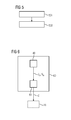
- Fig. 7 shows an embodiment of a sequence of method steps for operating a power grid 10 coupled to a generator 20 at a point of common coupling PCC.
- step 701 the grid properties Z G , V G of the power grid 10 are estimated by a method as described with reference to Fig. 2 or Fig. 3 .
- step 702 the power grid 10 is operated in dependence on the estimated grid properties Z G , V G .
- operating the power grid 10 may include diagnosis and maintenance of the power grid 10.
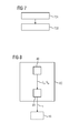
- Fig. 8 shows a schematic block diagram of an embodiment of an apparatus 80 for operating a power grid 10 coupled to a generator 20.
- the apparatus 80 of Fig. 8 includes a device 40 for estimating the grid properties Z G , V G .
- An example for such a device is depicted in Fig. 4 .
- the apparatus 80 includes an operating entity 81 which is configured to operate the power grid 10 in dependence on the estimated grid properties Z G , V G .
- the operating entity 81 may be embodied as a controller or a processor.
- the controller may use a control signal S which may be generated based on the estimated grid properties V G , Z G .
Landscapes
- Physics & Mathematics (AREA)
- General Physics & Mathematics (AREA)
- Engineering & Computer Science (AREA)
- Theoretical Computer Science (AREA)
- Power Engineering (AREA)
- Computer Hardware Design (AREA)
- Evolutionary Computation (AREA)
- Geometry (AREA)
- General Engineering & Computer Science (AREA)
- Control Of Eletrric Generators (AREA)
- Supply And Distribution Of Alternating Current (AREA)
Abstract
Description
- The present invention relates to a method and to a device for estimating grid properties of a power grid. Further, the present invention relates to a method and to an apparatus for controlling a generator coupled to a power grid as well as to a method and to an apparatus for operating a power grid.
- The grid properties of an electric power grid particularly include the grid impedance and the grid voltage. For example, these grid properties may be estimated by a Thevenin equivalent model of the electric grid.
- Thevenin's theory holds, to illustrate in DC circuit theory terms, that any linear electric network, here the electric power grid, with voltage and current sources, like generators and solar plants, and resistances can be replaced at terminals, here the point of common coupling, by an equivalent voltage source, here the grid voltage, in series connection with an equivalent resistance, here the grid impedance. The equivalent voltage is the voltage obtained at the point of common coupling in an open circuit. The equivalent resistance, here the grid impedance, is the resistance obtained at the point of common coupling with all its independent current sources open-circuited and all its independent voltage sources short-circuited.
- Conventionally, the grid properties of a power grid are estimated by driving the system to different steady-state points where the current and the voltage are measured, both the amplitude and the absolute phase of both variables. One problem here is the imprecision of the measurements of the absolute phase changes between different operating points due to frequency variations. In such a case, it may be enough to have two operating points for identifying the grid model, but more points may be used to minimize the error due to measurement noise. On the other hand, the problem regarding the absolute phase changes remains.
- For example, K.O.H. Pedersen, A.H. Nielsen and N.K. Poulsen describe in the article "Short-circuit impedance measurement" methods for estimating the short-circuit impedance in the power grid for various voltage levels and situations. The short-circuit impedance is measured, preferably based on naturally occurring load changes in the grid. They show that such a measurement system faces different kinds of problems at different locations in the grid. This means that the best measurement methodology changes depending on the location in the grid. Three typical examples with different measurement programs at 400 kV, 132 kV and 400 V voltage level are discussed there.
- Accordingly, it is an object of the present invention to provide an improved estimation of the grid properties of a power grid coupled to a generator.
- According to a first aspect, a method for estimating grid properties of a power grid coupled to a generator at a point of common coupling PCC is provided. In a first step, a voltage VPCC at the point of common coupling is measured. In a second step, a current IPCC at the point of common coupling is measured. In a third step, the grid properties are estimated by a grid model using as input parameters the measured voltage VPCC at the point of common coupling, the measured current IPCC at the point of common coupling and the determined phase angle.
- In the present method, the grid properties are estimated based on the measured voltage VPCC, the measured current IPCC and the determined phase angle between the voltage VPCC and the current IPCC. Thus, the absolute phases of the voltage VPCC and the current IPCC are not necessary, which makes the present method less prone to errors due to measurement noise.
- In particular, the minimum number of operating points needed here is three, but more operating points may be used to mitigate the influence of noise.
- By means of the present method it is possible to formulate a grid estimation problem as a solution of a set of quadratic polynomial equations whose coefficients are functions of the amplitude of the voltage VPCC, the amplitude of the current IPCC and the relative phase angle (or equivalently the magnitude of VPCC, the active power as well as the reactive power). Details for both are given in the following detailed description.
- In case of three operating points, the solution may also be found either analytically or numerically by applying appropriate equation solvers.
- According to an embodiment, the grid properties include a grid impedance ZG and a grid voltage VG of the power grid.
- Both, the estimated grid impedance and the estimated grid voltage may be of use for different technical applications. For example, the grid properties may be used for controlling a generator coupled to a power grid, wherein the generator is controlled in dependence on the estimated grid properties. Further, the estimated grid properties may be used to operate the power grid in dependence on said estimated grid properties.
- According to a further embodiment, the voltage VPCC at the point of common coupling and the current IPCC at the point of common coupling are measured at a fundamental frequency of the power grid. For example, the fundamental frequency is 50 Hz.
- According to a further embodiment, the method includes the following steps:
- a) measuring the voltage VPCC at the point of common coupling PCC at N different working points of the power grid, N ≥ 3,
- b) measuring the current IPCC at the point of common coupling PCC at the N different working points,
- c) determining the phase angle α between the measured voltage VPCC at the point of common coupling PCC and the measured current IPCC at the point of common coupling PCC for each of the N different working points, and
- d) estimating the grid properties by the grid model using as input parameters the measured voltage VPCC at the point of common coupling PCC, the measured current IPCC at the point of common coupling PCC and the determined phase angle α for the N different working points.
- In particular, method steps a) to c) may be executed iteratively. The number of iterations is defined by N. Each iteration step of steps a) to c) provides a tuple of {VPCC, IPCC, α}. Based on said N tuples {VPCC, IPCC, α}, the grid properties are estimated in step d).
- In particular, step d) includes eliminating the absolute phases of the measured voltage VPCC at the point of common coupling and the measured current IPCC at the point of common coupling.
- Two examples for eliminating the absolute phases of the voltage VPCC at the point of common coupling and the current IPCC at the point of common coupling are given in the detailed description of
Fig. 3 . - According to a further embodiment, the grid properties include a resistive part R of the grid impedance ZG, a reactive part X of the grid impedance ZG and the grid voltage VG of the power grid.
- According to a further embodiment, the resistive part R of the grid impedance ZG, the reactive part X of the grid impedance ZG and the grid voltage VG are determined by solving the following equation for three different working points:

- In the above equation, VPCC indicates the measured voltage at the point of common coupling PCC, IPCC indicates the measured current at the point of common coupling PCC, and α indicates the determined phase angle between the measured voltage VPCC at the point of common coupling PCC and the measured current IPCC at the point of common coupling PCC.
- In the above equation, no absolute phases of the voltage VPCC at the point of common coupling and the current IPCC at the point of common coupling are used. As a result, the present method is less prone to errors due to measurement noise. A detailed derivation of the above equation is given in the detailed description of the Figures.
- According to a further embodiment, the resistive part R of the grid impedance ZG, the reactive part X of the grid impedance ZG and the grid voltage VG are determined by solving the following equation for three different working points:

- In the above equation, VPCC indicates the voltage at the point of common coupling PCC, P indicates the active power injected at the point of common coupling PCC, and Q indicates the reactive power injected at the point of common coupling PCC.
- This equation is an equivalent formulation to the above equation. In the above equation, no absolute phases of the voltage VPCC at the point of common coupling and the current IPCC at the point of common coupling are used. As a result, the present method is less prone to errors due to measurement noise. A detailed revelation of above equation is given in the detailed description of the Figures.
- According to a further embodiment, the generator is a wind turbine coupled at the point of common coupling to a low-voltage power grid.
- Any embodiment of the first aspect may be combined with any embodiment of the first aspect to obtain another embodiment of the first aspect.
- According to a second aspect, the invention relates to a computer program product comprising a program code for executing the above discussed method for estimating grid properties of a power grid coupled to a generator at a point of common coupling when run on at least one computer.
- A computer program product, like a computer program means, may be embodied as a memory card, USB stick, CD-ROM, DVD or as a file which may be downloaded from a server in a network. For example, this may be provided by transferring the respective file with the computer program product from a wireless communication network.
- According to a third aspect, a device for estimating grid properties of a power grid coupled to a generator at a point of common coupling is provided. The device includes a first sensor, a second sensor, a determiner, and a processor. The first sensor is configured to measure a voltage VPCC at the point of common coupling. The second sensor is configured to measure a current IPCC at the point of common coupling. The determiner is configured to determine a phase angle α between the measured voltage VPCC at the point of common coupling and the measured current IPCC at the point of common coupling. Further, the processor is configured to estimate the grid properties by a grid model using as input parameters the measured voltage VPCC at the point of common coupling, the measured current IPCC at the point of common coupling and the determined phase angle α.
- According to a fourth aspect, a method for controlling a generator coupled to a power grid by a point of common coupling is provided. In a first step, the grid properties of the power grid are estimated according to a method of above mentioned first aspect. In a second step, the generator is controlled in dependence on or based on the estimated grid properties.
- According to a fifth aspect, the invention relates to a computer program product comprising a program code for executing the above discussed method for controlling a generator coupled to a power grid by a point of common coupling when run on at least one computer.
- According to a sixth aspect, an apparatus for controlling a generator coupled to a power grid by a point of common coupling is provided. The apparatus includes a device for estimating grid properties of the power grid according to the above mentioned third aspect. Moreover, the apparatus includes a controller for controlling the generator in dependence on the estimated grid properties.
- According to a seventh aspect, a method for operating a power grid coupled to a generator by a point of common coupling is provided. In a first step, the grid properties of the power grid are estimated according to a method of above mentioned first aspect. In a second step, the power grid is operated in dependence on the estimated grid properties. In particular, the power grid is controlled based on the estimated grid properties.
- According to an eighth aspect, an apparatus for operating a power grid coupled to a generator at a point of common coupling is provided. The apparatus includes a device for estimating grid properties of the power grid according to the above mentioned third aspect. Moreover, the apparatus includes an operating entity for operating the power grid in dependence on the estimated grid properties. The operating entity may be a controller. This controller may be adapted to control the power grid based on the estimated grid properties.
- The respective means, e.g. the determiner, the processor or a controller, may be implemented in hardware and/or in software. If said means are implemented in hardware, it may be embodied as a device, e.g. as a computer or as a processor or as a part of a system, e.g. a computer system. If said means are implemented in software it may be embodied as a computer program product, as a function, as a routine, as a program code or as an executable object.
- Further objects, features and advantages of the present invention will become apparent from the subsequent description and depending claims, taking in conjunction with the accompanying drawings, in which:
- Fig. 1
- shows an equivalent model of a power grid coupled to a generator at a point of common coupling;
- Fig. 2
- shows a first embodiment of a sequence of method steps for estimating grid properties of a power grid coupled to a generator;
- Fig. 3
- shows a second embodiment of a sequence of method steps for estimating grid properties of a power grid coupled to a generator;
- Fig. 4
- shows a schematic block diagram of an embodiment of a device for estimating grid properties of a power grid coupled to a generator;
- Fig. 5
- shows an embodiment of a sequence of method steps for controlling a generator coupled to a power grid by a point of common coupling;
- Fig. 6
- shows a schematic block diagram of an embodiment of an apparatus for controlling a generator coupled to a power grid;
- Fig. 7
- shows an embodiment of a sequence of method steps for operating a power grid coupled to a generator; and
- Fig. 8
- shows a schematic block diagram of an embodiment of an apparatus for operating a power grid coupled to a generator.
- In the Figures, like reference numerals designate like or functionally equivalent elements, unless otherwise indicated.
- Further, in the Figures, the following symbols are used for discussing said embodiments for estimating grid properties of a power grid coupled to a generator at a point of common coupling:
Symbol Definition Type Measured / Unknown/determi ned from measurements VG Grid voltage, used as reference for the phase real Unknown ZG Grid impedance complex unknown R Resistive part of ZG real unknown X Reactive part of ZG real Unknown ZG = R + j * X VPCC Voltage at the point of common coupling complex Partially unknown VPCC Magnitude of VPCC real Measured θ Phase of VPCC with respect to VG Real unknown VPCC = |VPCC| ej*θ IPCC Current injected at the point of common coupling complex partially unknown |IPCC| Magnitude of IPCC real Measured ϕ Phase of IPCC with respect to VG real unknown IPCC = |IPCC| ej*ϕ α Phase between voltage and current real measured α = θ - ϕ PPCC Active power injected at PCC real determined PPCC = |UPCC| * |IPCC| *cos(α) QPCC Reactive power injected at PCC real determined QPCC = |UPCC| * |IPCC| * sin (α) SPCC Apparent power injected at PCC Complex determined SPCC = PPCC + j*QPCC = UPCC*conj (IPCC) - In this regard,
Fig. 1 shows an equivalent model of apower grid 10 coupled to agenerator 20 at a point of common coupling PCC. - As illustrated in
Fig. 1 , thepower grid 10 is modelled by its grid impedance ZG and its grid voltage VPCC at the point of common coupling PCC. At the point of common coupling PCC, the voltage VPCC at the PCC, the current IPCC injected at the PCC, the active power PPCC injected at the PCC, and the reactive power QPCC injected at the PCC are depicted. - Further,
Fig. 2 shows a first embodiment of a sequence of method steps for estimating grid properties ZG, VG of thepower grid 10 coupled to thegenerator 20 at the point of common coupling PCC as shown inFig. 1 . - In particular, the
power grid 10 is a low-voltage power grid, and thegenerator 20 is a wind turbine coupled to the low-voltage power grid 10 at the point of common coupling PCC. - The method of
Fig. 2 comprises the steps 101 - 104: Instep 101, the voltage VPCC at the point of common coupling PCC is measured. Instep 102, the current IPCC at the point of common coupling PCC is measured. - In particular, the voltage VPCC and the current IPCC are measured at a fundamental frequency of the
power grid 10. For example, the fundamental frequency of thepower grid 10 is 50 Hz. - In
step 103, the phase angle α between the measured voltage VPCC and the measured current IPCC is determined. - In
step 104, the grid properties ZG, VG are estimated or determined by a grid model. The grid model uses the measured voltage VPCC, the measured current IPCC and the determined phase angle α. The grid properties include the grid impedance ZG and the grid voltage VG of thepower grid 10. -
Fig. 3 shows a second embodiment of a sequence of method steps for estimating grid properties ZG, VG of thepower grid 10. - The method of
Fig. 3 includes the method steps 201 - 204. In this regard, the method steps 201 - 203 are executed for at least three times at different working points of the system. - For example, the system of
Fig. 1 including thepower grid 10 and thegenerator 20 coupled at the point of common coupling PCC is driven to the at least three working points, where the voltage VPCC is measured (step 201), the current IPCC is measured (step 202) and the phase angle α between the measured VPCC and the measured IPCC is determined. - As a result of method steps 201 - 203, there are at least three tuples of {VPCC, IPCC, α}. Based on the tuples {VPCC, IPCC, α}, in
step 204, the grid properties ZG, VG are estimated or determined by a grid model. The grid model uses as input tuples of VPCC, IPCC, and α determined at a minimum of three different working points. - Within said
step 204, the absolute phases ϑ, ϕ of VPCC and IPCC are not used. In the following, this is explained for two different examples in which ϑ, ϕ are eliminated. In these two examples, the resistive part R of the grid impedance ZG, the reactive part X of the grid impedance ZG and the grid voltage VG are determined. - According to a first example, with respect to
Fig. 1 , the resistive part R, the reactive part X and the grid voltage VG may be determined by a first formulation with the voltage magnitude |VPCC|, the current magnitude |IPCC| and the phase α between the voltage VPCC at the point of common coupling and the current IPCC at the point of common coupling:


- According to a second example, and with respect to
Fig. 1 , R, X, VG may be determined by a second formulation with the voltage magnitude |VPCC|, the reactive power P (or PPCC) and the reactive power Q (or QPCC) :


- In
Fig. 4 , a schematic block diagram of an embodiment of adevice 40 for estimating grid properties ZG, VG of apower grid 10 coupled to agenerator 20 at the point of common coupling is depicted (seeFig. 1 ). - The
device 40 ofFig. 4 comprises afirst sensor 41, asecond sensor 42, adeterminer 43 and aprocessor 44. Thefirst sensor 41 may be coupled to thedeterminer 43 and theprocessor 44. Thesecond sensor 42 may be coupled to thedeterminer 43 and theprocessor 44. Thedeterminer 43 may be coupled to theprocessor 44. - The
first sensor 41 is adapted to measure the voltage VPCC and the point of common coupling PCC. Thesecond sensor 42 is adapted to measure the current IPCC at the point of common coupling PCC. Thedeterminer 43 is adapted to determine the phase angle α between the measured voltage VPCC at the point of common coupling PCC and the measured current IPCC at the point of common coupling PCC. - The
processor 44 is adapted to estimate or to determine the grid properties ZG, VG by a grid model, said grid model using as input parameters the measured voltage VPCC, the measured current IPCC and the determined phase angle α. -
Fig. 5 shows an embodiment of a sequence of method steps for controlling agenerator 20 coupled to apower grid 10 at a point of common coupling PCC. The method ofFig. 5 comprises thesteps - In
step 501, the grid properties VG, ZG of thepower grid 10 are estimated. Embodiments for theestimation step 501 are given byFigs. 2 and3 . - In
step 502, thegenerator 20 is controlled or adjusted in dependence on the estimated grid properties ZG, VG. In particular, thegenerator 20 is controlled based on the estimated grid properties ZG, VG. -
Fig. 6 shows as schematic block diagram of an embodiment of anapparatus 60 for controlling agenerator 20 coupled to apower grid 10 at a point of common coupling PCC. Theapparatus 60 ofFig. 6 comprises adevice 40 for estimating grid properties ZG, VG of thepower grid 10. An example for such adevice 40 is depicted inFig. 4 . - Further, the
apparatus 60 ofFig. 6 includes acontroller 61 which is configured to control thegenerator 20 in dependence on the estimated grid properties ZG, VG. For controlling thegenerator 20, thecontroller 61 may use a control signal C which is generated in dependence on the estimated grid properties ZG, VG. -
Fig. 7 shows an embodiment of a sequence of method steps for operating apower grid 10 coupled to agenerator 20 at a point of common coupling PCC. - In
step 701, the grid properties ZG, VG of thepower grid 10 are estimated by a method as described with reference toFig. 2 orFig. 3 . - In
step 702, thepower grid 10 is operated in dependence on the estimated grid properties ZG, VG. In particular, operating thepower grid 10 may include diagnosis and maintenance of thepower grid 10. -
Fig. 8 shows a schematic block diagram of an embodiment of anapparatus 80 for operating apower grid 10 coupled to agenerator 20. Theapparatus 80 ofFig. 8 includes adevice 40 for estimating the grid properties ZG, VG. An example for such a device is depicted inFig. 4 . - Further, the
apparatus 80 includes anoperating entity 81 which is configured to operate thepower grid 10 in dependence on the estimated grid properties ZG, VG. The operatingentity 81 may be embodied as a controller or a processor. For controlling thepower grid 10, the controller may use a control signal S which may be generated based on the estimated grid properties VG, ZG. - Although the present invention has been described in accordance with preferred embodiments, it is obvious for a person skilled in the art that modifications are possible in all embodiments.
Claims (15)
- A method for estimating grid properties (ZG, VG) of a power grid (10) coupled to a generator (20) at a point of common coupling (PCC), the method comprising:measuring (101) a voltage (VPCC) at the point of common coupling (PCC),measuring (102) a current (IPCC) at the point of common coupling (PCC),determining (103) a phase angle (α) between the measured voltage (VPCC) at the point of common coupling (PCC) and the measured current (IPCC) at the point of common coupling (PCC), andestimating (104) the grid properties (ZG, VG) by a grid model using as input parameters the measured voltage (VPCC) at the point of common coupling (PCC), the measured current (IPCC) at the point of common coupling (PCC) and the determined phase angle α.
- The method of claim 1,
wherein the grid properties (ZG, VG) include grid impedance (ZG) and a grid voltage (VG) of the power grid (10). - The method of claim 1 or 2,
wherein the voltage (VPCC) at the point of common coupling (PCC) and the current (IPCC) at the point of common coupling (PCC) are measured at a fundamental frequency of the power grid (10). - The method of one of claims 1 to 3,
comprising the following steps:a) measuring (201) the voltage (VPCC) at the point of common coupling (PCC) at N different working points of the power grid (10), N ≥ 3,b) measuring (202) the current (IPCC) at the point of common coupling (PCC) at the N different working points,c) determining (203) the phase angle (α) between the measured voltage (VPCC) at the point of common coupling (PCC) and the measured current (IPCC) at the point of common coupling (PCC) for each of the N different working points,
andd) estimating (204) the grid properties (ZG, VG) by the grid model using as input parameters the measured voltage (VPCC) at the point of common coupling (PCC), the measured current (IPCC) at the point of common coupling (PCC) and the determined phase angle (α) for the N different working points. - The method of claim 4,
wherein step d) (204) includes eliminating the absolute phases of the measured voltage (VPCC) at the point of common coupling (PCC) and the measured current (IPCC) at the point of common coupling (PCC). - The method of claim 4 or 5,
wherein the grid properties (ZG, VG) include a resistive part (R) of the grid impedance (ZG), a reactive part (X) of the grid impedance (ZG) and the grid voltage (VG) of the power grid. - The method of claim 6,
wherein the resistive part (R) of the grid impedance (ZG), the reactive part (X) of the grid impedance (ZG) and the grid voltage (VG) are determined by solving the following equation for three different working points:
wherein VPCC indicates the measured voltage at the point of common coupling (PCC), IPCC indicates the measured current at the point of common coupling (PCC), and α indicates the determined phase angle between the measured voltage at the point of common coupling (PCC) and the measured current at the point of common coupling (PCC). - The method of claim 6,
wherein the resistive part (R) of the grid impedance (ZG), the reactive part (X) of the grid impedance (ZG) and the grid voltage (VG) are determined by solving the following equation for three different working points:
wherein VPCC indicates the voltage at the point of common coupling (PCC), P indicates the active power injected at the point of common coupling (PCC), and Q indicates the reactive power injected at the point of common coupling (PCC). - The method of one of claims 1 to 8,
wherein the generator (20) is a wind turbine coupled by the point of common coupling (PCC) to a low-voltage power grid (10). - A device (40) for estimating grid properties (ZG, VG) of a power grid (10) coupled to a generator (20) at a point of common coupling (PCC), the device (40) comprising:a first sensor (41) for measuring a voltage (VPCC) at the point of common coupling (PCC),a second sensor (42) for measuring a current (IPCC) at the point of common coupling (PCC),a determiner (43) for determining a phase angle (α) between the measured voltage (VPCC) at the point of common coupling (PCC) and the measured current (IPCC) at the point of common coupling (PCC), anda processor (44) for estimating the grid properties (ZG, VG) by a grid model using as input parameters the measured voltage (VPCC) at the point of common coupling (PCC), the measured current (IPCC) at the point of common coupling (PCC) and the determined phase angle (α).
- A method for controlling a generator (20) coupled to a power grid (10) by a point of common coupling (PCC), the method comprising:estimating (501) the grid properties (ZG, VG) of the power grid (10) by a method of one of claims 1 to 9, andcontrolling (502) the generator (20) in dependence on the estimated grid properties (ZG, VG).
- An apparatus (60) for controlling a generator (20) coupled to a power grid (10) by a point of common coupling (PCC), the apparatus (60) comprising:a device (40) for estimating grid properties (ZG, VG) of the power grid (10) of claim 10, anda controller (61) for controlling the generator (20) in dependence on the estimated grid properties.
- A method for operating a power grid (10) coupled to a generator (20) by a point of common coupling (PCC), the method comprising:estimating (701) the grid properties (ZG, VG) of the power grid (10) by a method of one of claims 1 to 9, andoperating (702) the power grid (10) in dependence on the estimated grid properties (ZG, VG).
- The method of claim 13,
wherein operating (702) the power grid (10) includes diagnosis and maintenance of the power grid (10). - An apparatus (80) for operating a power grid (10) coupled to a generator (20) at a point of common coupling (PCC), the apparatus (80) comprising:a device (40) for estimating the grid properties (ZG, VG) of claim 10, andan operating entity (81) for operating the power grid (10) in dependence on the estimated grid properties (ZG, VG).
Priority Applications (3)
| Application Number | Priority Date | Filing Date | Title |
|---|---|---|---|
| EP13176978.8A EP2827157B1 (en) | 2013-07-18 | 2013-07-18 | Method and device for estimating grid properties of a power grid |
| US14/318,598 US10296669B2 (en) | 2013-07-18 | 2014-06-28 | Method and device for estimating grid properties of a power grid |
| CN201410343097.6A CN104300530A (en) | 2013-07-18 | 2014-07-18 | Method and device for estimating grid properties of a power grid |
Applications Claiming Priority (1)
| Application Number | Priority Date | Filing Date | Title |
|---|---|---|---|
| EP13176978.8A EP2827157B1 (en) | 2013-07-18 | 2013-07-18 | Method and device for estimating grid properties of a power grid |
Publications (2)
| Publication Number | Publication Date |
|---|---|
| EP2827157A1 true EP2827157A1 (en) | 2015-01-21 |
| EP2827157B1 EP2827157B1 (en) | 2019-03-06 |
Family
ID=48795466
Family Applications (1)
| Application Number | Title | Priority Date | Filing Date |
|---|---|---|---|
| EP13176978.8A Active EP2827157B1 (en) | 2013-07-18 | 2013-07-18 | Method and device for estimating grid properties of a power grid |
Country Status (3)
| Country | Link |
|---|---|
| US (1) | US10296669B2 (en) |
| EP (1) | EP2827157B1 (en) |
| CN (1) | CN104300530A (en) |
Cited By (4)
| Publication number | Priority date | Publication date | Assignee | Title |
|---|---|---|---|---|
| CN105356462A (en) * | 2015-12-03 | 2016-02-24 | 上海电机学院 | Wind farm harmonic evaluation prediction method |
| WO2017174797A1 (en) * | 2016-04-08 | 2017-10-12 | Abb Schweiz Ag | Islanding detection in an electrical power grid |
| EP3637574A1 (en) | 2018-10-11 | 2020-04-15 | Universidade de Vigo | Method for estimating electrical parameters of a grid |
| EP3828557A1 (en) * | 2019-11-28 | 2021-06-02 | ABB Schweiz AG | Determining thevenin equivalent model for a converter |
Families Citing this family (7)
| Publication number | Priority date | Publication date | Assignee | Title |
|---|---|---|---|---|
| EP3299826A1 (en) | 2016-09-27 | 2018-03-28 | ABB Schweiz AG | Method to estimate an equivalent grid impedance for power generators |
| JP6349561B1 (en) * | 2017-07-31 | 2018-07-04 | 福井県 | 3D modeling method |
| US10742068B2 (en) * | 2018-12-31 | 2020-08-11 | PXiSE Energy Solutions, LLC | Real-time deviation detection of power system electrical characteristics using time-synchronized measurements |
| US10985611B2 (en) | 2019-04-10 | 2021-04-20 | General Electric Company | System and method for estimating grid strength |
| CN114342202B (en) | 2019-07-03 | 2025-05-16 | 维斯塔斯风力系统集团公司 | Methods for network impedance and dynamics estimation |
| CA3174426A1 (en) | 2020-04-02 | 2021-10-07 | Abhineet H. PARCHURE | Electrical grid control systems and methods using dynamically mapped effective impedance |
| EP4697537A1 (en) * | 2024-08-16 | 2026-02-18 | Siemens Gamesa Renewable Energy A/S | Estimating grid impedance |
Citations (5)
| Publication number | Priority date | Publication date | Assignee | Title |
|---|---|---|---|---|
| DE3600770A1 (en) * | 1986-01-14 | 1986-11-20 | Eckhard Dipl.-Ing. 7507 Pfinztal Hoffmann | Measurement method for determining the operating frequency network impedances of the high-voltage network (grid) with the aid of a transformer connection |
| DE19910288A1 (en) * | 1999-03-09 | 2000-09-14 | Sauter Martin | Method for monitoring network impedance using photovoltaic power supply device by measuring feedback on inputting point of power supply network as change of power generator performance of photovoltaic module |
| US20030098671A1 (en) * | 2001-11-26 | 2003-05-29 | Visteon Global Technologies, Inc. | Anti-islanding detection scheme for distributed power generation |
| EP1841037A2 (en) * | 2006-03-29 | 2007-10-03 | General Electric Company | System, method, and article of manufacture for determining parameter values associated with an electrical grid |
| US20130148394A1 (en) * | 2011-12-13 | 2013-06-13 | Kathleen Ann O'Brien | Methods and systems for controlling a power conversion device |
Family Cites Families (4)
| Publication number | Priority date | Publication date | Assignee | Title |
|---|---|---|---|---|
| US7945430B2 (en) * | 2000-09-29 | 2011-05-17 | Canning Francis X | Compression and compressed inversion of interaction data |
| CN101680922B (en) | 2007-02-27 | 2013-04-17 | Osi软件公司 | Impedance measurement of a power line |
| US10382285B2 (en) * | 2011-08-25 | 2019-08-13 | Siemens Industry, Inc. | Smart grid communication assessment and co-simulation tool |
| US20130218355A1 (en) * | 2012-02-16 | 2013-08-22 | Spyros James Lazaris | Electricity grid data analytics as a moduled service for production, delivery, and distribution of power as a dynamic demand response within a renewable energy-based electricity grid infrastructure |
-
2013
- 2013-07-18 EP EP13176978.8A patent/EP2827157B1/en active Active
-
2014
- 2014-06-28 US US14/318,598 patent/US10296669B2/en active Active
- 2014-07-18 CN CN201410343097.6A patent/CN104300530A/en active Pending
Patent Citations (5)
| Publication number | Priority date | Publication date | Assignee | Title |
|---|---|---|---|---|
| DE3600770A1 (en) * | 1986-01-14 | 1986-11-20 | Eckhard Dipl.-Ing. 7507 Pfinztal Hoffmann | Measurement method for determining the operating frequency network impedances of the high-voltage network (grid) with the aid of a transformer connection |
| DE19910288A1 (en) * | 1999-03-09 | 2000-09-14 | Sauter Martin | Method for monitoring network impedance using photovoltaic power supply device by measuring feedback on inputting point of power supply network as change of power generator performance of photovoltaic module |
| US20030098671A1 (en) * | 2001-11-26 | 2003-05-29 | Visteon Global Technologies, Inc. | Anti-islanding detection scheme for distributed power generation |
| EP1841037A2 (en) * | 2006-03-29 | 2007-10-03 | General Electric Company | System, method, and article of manufacture for determining parameter values associated with an electrical grid |
| US20130148394A1 (en) * | 2011-12-13 | 2013-06-13 | Kathleen Ann O'Brien | Methods and systems for controlling a power conversion device |
Non-Patent Citations (3)
| Title |
|---|
| CIOBOTARU M ET AL: "Online grid impedance estimation for single-phase grid-connected systems using PQ variations", POWER ELECTRONICS SPECIALISTS CONFERENCE, 2007. PESC 2007. IEEE, IEEE, PISCATAWAY, NJ, USA, 17 June 2007 (2007-06-17), pages 2306 - 2312, XP031218627, ISBN: 978-1-4244-0654-8 * |
| K.O.H. PEDERSEN; A.H. NIELSEN; N.K. POULSEN, SHORT-CIRCUIT IMPEDANCE MEASUREMENT |
| TIMBUS A V ET AL: "Line Impedance Estimation Using Active and Reactive Power Variations", POWER ELECTRONICS SPECIALISTS CONFERENCE, 2007. PESC 2007. IEEE, IEEE, PISCATAWAY, NJ, USA, 17 June 2007 (2007-06-17), pages 1273 - 1279, XP031218468, ISBN: 978-1-4244-0654-8 * |
Cited By (8)
| Publication number | Priority date | Publication date | Assignee | Title |
|---|---|---|---|---|
| CN105356462A (en) * | 2015-12-03 | 2016-02-24 | 上海电机学院 | Wind farm harmonic evaluation prediction method |
| CN105356462B (en) * | 2015-12-03 | 2017-12-08 | 上海电机学院 | Wind power plant harmonic prediction appraisal procedure |
| WO2017174797A1 (en) * | 2016-04-08 | 2017-10-12 | Abb Schweiz Ag | Islanding detection in an electrical power grid |
| US10852336B2 (en) | 2016-04-08 | 2020-12-01 | Abb Schweiz Ag | Islanding detection in an electrical power grid |
| EP3637574A1 (en) | 2018-10-11 | 2020-04-15 | Universidade de Vigo | Method for estimating electrical parameters of a grid |
| EP3637574B1 (en) * | 2018-10-11 | 2024-02-21 | Universidade de Vigo | Method for estimating electrical parameters of a grid |
| EP3828557A1 (en) * | 2019-11-28 | 2021-06-02 | ABB Schweiz AG | Determining thevenin equivalent model for a converter |
| US11709976B2 (en) | 2019-11-28 | 2023-07-25 | Abb Schweiz Ag | Determining Thevenin equivalent model for a converter system |
Also Published As
| Publication number | Publication date |
|---|---|
| EP2827157B1 (en) | 2019-03-06 |
| US20150025860A1 (en) | 2015-01-22 |
| CN104300530A (en) | 2015-01-21 |
| US10296669B2 (en) | 2019-05-21 |
Similar Documents
| Publication | Publication Date | Title |
|---|---|---|
| EP2827157B1 (en) | Method and device for estimating grid properties of a power grid | |
| EP2957918B1 (en) | Synchronous phasor measurement method applicable to p-type phasor measurement unit (mpu) | |
| JP6491424B2 (en) | Harmonic estimation device, harmonic estimation method, and harmonic estimation program | |
| CN110546881B (en) | Segmented estimation of negative sequence voltage for fault detection in electrical systems | |
| US10209310B2 (en) | Rotary machine diagnostic system | |
| CN106054023B (en) | A method for estimating system impedance on both sides of transmission line in single-ended ranging | |
| CN102288804B (en) | Method for calculating resistive current of arrester based on orthogonal transformation | |
| CN104380124A (en) | Apparatus and method of fault detection and location determination | |
| US20180011136A1 (en) | Fault point locating device and method, electric power system monitoring system, and facility planning support system | |
| JP5992650B1 (en) | Diagnostic equipment for electric motors | |
| CN110062889A (en) | System and method for detecting the stator failure in alternating current generator | |
| JP6161783B2 (en) | Method for obtaining impedance of power transmission / distribution network by computer support, power generation apparatus and computer program for implementing the method | |
| US20160169974A1 (en) | Automated motor adaptation | |
| Huang et al. | Dynamic state estimation for power systems with uncertain inputs | |
| BR102015021673B1 (en) | DISTANCE PROTECTION METHOD FOR HALF-WAVELENGTH LINES AND USE OF THE SAME | |
| US12153116B2 (en) | Method and system for monitoring power lines | |
| JP5078763B2 (en) | Transmission line accident location device and transmission line accident location method | |
| CN108957097A (en) | Measurement method of resistive current fundamental wave of metal oxide arrester | |
| CN112580225A (en) | On-line identification method for damping coefficient and rotational inertia of synchronous inverter | |
| CN109100649B (en) | Parameter estimation method for generator excitation system and speed regulation system based on phasor measurement | |
| RU2308731C1 (en) | Method for determining location of one-phased ground short circuit with usage of a model of power lines in emergency mode | |
| Lee et al. | Distance relaying algorithm using a DFT-based modified phasor estimation method | |
| KR20150022111A (en) | Apparatus and Method for detecting fails of Alternating Current motor | |
| Arabaci et al. | A novel motor speed calculation method using square wave speed sensor signals via fast Fourier transform | |
| RU2486532C1 (en) | Device to control deformation of power transformer windings |
Legal Events
| Date | Code | Title | Description |
|---|---|---|---|
| 17P | Request for examination filed |
Effective date: 20130718 |
|
| AK | Designated contracting states |
Kind code of ref document: A1 Designated state(s): AL AT BE BG CH CY CZ DE DK EE ES FI FR GB GR HR HU IE IS IT LI LT LU LV MC MK MT NL NO PL PT RO RS SE SI SK SM TR |
|
| AX | Request for extension of the european patent |
Extension state: BA ME |
|
| PUAI | Public reference made under article 153(3) epc to a published international application that has entered the european phase |
Free format text: ORIGINAL CODE: 0009012 |
|
| R17P | Request for examination filed (corrected) |
Effective date: 20150706 |
|
| RBV | Designated contracting states (corrected) |
Designated state(s): AL AT BE BG CH CY CZ DE DK EE ES FI FR GB GR HR HU IE IS IT LI LT LU LV MC MK MT NL NO PL PT RO RS SE SI SK SM TR |
|
| RAP1 | Party data changed (applicant data changed or rights of an application transferred) |
Owner name: SIEMENS AKTIENGESELLSCHAFT |
|
| STAA | Information on the status of an ep patent application or granted ep patent |
Free format text: STATUS: EXAMINATION IS IN PROGRESS |
|
| 17Q | First examination report despatched |
Effective date: 20180323 |
|
| GRAP | Despatch of communication of intention to grant a patent |
Free format text: ORIGINAL CODE: EPIDOSNIGR1 |
|
| STAA | Information on the status of an ep patent application or granted ep patent |
Free format text: STATUS: GRANT OF PATENT IS INTENDED |
|
| INTG | Intention to grant announced |
Effective date: 20180926 |
|
| GRAS | Grant fee paid |
Free format text: ORIGINAL CODE: EPIDOSNIGR3 |
|
| GRAA | (expected) grant |
Free format text: ORIGINAL CODE: 0009210 |
|
| STAA | Information on the status of an ep patent application or granted ep patent |
Free format text: STATUS: THE PATENT HAS BEEN GRANTED |
|
| AK | Designated contracting states |
Kind code of ref document: B1 Designated state(s): AL AT BE BG CH CY CZ DE DK EE ES FI FR GB GR HR HU IE IS IT LI LT LU LV MC MK MT NL NO PL PT RO RS SE SI SK SM TR |
|
| REG | Reference to a national code |
Ref country code: GB Ref legal event code: FG4D |
|
| REG | Reference to a national code |
Ref country code: CH Ref legal event code: EP Ref country code: AT Ref legal event code: REF Ref document number: 1105265 Country of ref document: AT Kind code of ref document: T Effective date: 20190315 |
|
| REG | Reference to a national code |
Ref country code: DE Ref legal event code: R096 Ref document number: 602013051718 Country of ref document: DE |
|
| REG | Reference to a national code |
Ref country code: IE Ref legal event code: FG4D |
|
| REG | Reference to a national code |
Ref country code: DE Ref legal event code: R081 Ref document number: 602013051718 Country of ref document: DE Owner name: SIEMENS GAMESA RENEWABLE ENERGY A/S, DK Free format text: FORMER OWNER: SIEMENS AKTIENGESELLSCHAFT, 80333 MUENCHEN, DE |
|
| RAP2 | Party data changed (patent owner data changed or rights of a patent transferred) |
Owner name: SIEMENS GAMESA RENEWABLE ENERGY A/S |
|
| REG | Reference to a national code |
Ref country code: NL Ref legal event code: MP Effective date: 20190306 |
|
| REG | Reference to a national code |
Ref country code: LT Ref legal event code: MG4D |
|
| PG25 | Lapsed in a contracting state [announced via postgrant information from national office to epo] |
Ref country code: NO Free format text: LAPSE BECAUSE OF FAILURE TO SUBMIT A TRANSLATION OF THE DESCRIPTION OR TO PAY THE FEE WITHIN THE PRESCRIBED TIME-LIMIT Effective date: 20190606 Ref country code: LT Free format text: LAPSE BECAUSE OF FAILURE TO SUBMIT A TRANSLATION OF THE DESCRIPTION OR TO PAY THE FEE WITHIN THE PRESCRIBED TIME-LIMIT Effective date: 20190306 Ref country code: SE Free format text: LAPSE BECAUSE OF FAILURE TO SUBMIT A TRANSLATION OF THE DESCRIPTION OR TO PAY THE FEE WITHIN THE PRESCRIBED TIME-LIMIT Effective date: 20190306 Ref country code: FI Free format text: LAPSE BECAUSE OF FAILURE TO SUBMIT A TRANSLATION OF THE DESCRIPTION OR TO PAY THE FEE WITHIN THE PRESCRIBED TIME-LIMIT Effective date: 20190306 |
|
| PG25 | Lapsed in a contracting state [announced via postgrant information from national office to epo] |
Ref country code: NL Free format text: LAPSE BECAUSE OF FAILURE TO SUBMIT A TRANSLATION OF THE DESCRIPTION OR TO PAY THE FEE WITHIN THE PRESCRIBED TIME-LIMIT Effective date: 20190306 Ref country code: RS Free format text: LAPSE BECAUSE OF FAILURE TO SUBMIT A TRANSLATION OF THE DESCRIPTION OR TO PAY THE FEE WITHIN THE PRESCRIBED TIME-LIMIT Effective date: 20190306 Ref country code: HR Free format text: LAPSE BECAUSE OF FAILURE TO SUBMIT A TRANSLATION OF THE DESCRIPTION OR TO PAY THE FEE WITHIN THE PRESCRIBED TIME-LIMIT Effective date: 20190306 Ref country code: LV Free format text: LAPSE BECAUSE OF FAILURE TO SUBMIT A TRANSLATION OF THE DESCRIPTION OR TO PAY THE FEE WITHIN THE PRESCRIBED TIME-LIMIT Effective date: 20190306 Ref country code: BG Free format text: LAPSE BECAUSE OF FAILURE TO SUBMIT A TRANSLATION OF THE DESCRIPTION OR TO PAY THE FEE WITHIN THE PRESCRIBED TIME-LIMIT Effective date: 20190606 Ref country code: GR Free format text: LAPSE BECAUSE OF FAILURE TO SUBMIT A TRANSLATION OF THE DESCRIPTION OR TO PAY THE FEE WITHIN THE PRESCRIBED TIME-LIMIT Effective date: 20190607 |
|
| REG | Reference to a national code |
Ref country code: AT Ref legal event code: MK05 Ref document number: 1105265 Country of ref document: AT Kind code of ref document: T Effective date: 20190306 |
|
| REG | Reference to a national code |
Ref country code: GB Ref legal event code: 732E Free format text: REGISTERED BETWEEN 20190822 AND 20190828 |
|
| PG25 | Lapsed in a contracting state [announced via postgrant information from national office to epo] |
Ref country code: EE Free format text: LAPSE BECAUSE OF FAILURE TO SUBMIT A TRANSLATION OF THE DESCRIPTION OR TO PAY THE FEE WITHIN THE PRESCRIBED TIME-LIMIT Effective date: 20190306 Ref country code: AL Free format text: LAPSE BECAUSE OF FAILURE TO SUBMIT A TRANSLATION OF THE DESCRIPTION OR TO PAY THE FEE WITHIN THE PRESCRIBED TIME-LIMIT Effective date: 20190306 Ref country code: PT Free format text: LAPSE BECAUSE OF FAILURE TO SUBMIT A TRANSLATION OF THE DESCRIPTION OR TO PAY THE FEE WITHIN THE PRESCRIBED TIME-LIMIT Effective date: 20190706 Ref country code: SK Free format text: LAPSE BECAUSE OF FAILURE TO SUBMIT A TRANSLATION OF THE DESCRIPTION OR TO PAY THE FEE WITHIN THE PRESCRIBED TIME-LIMIT Effective date: 20190306 Ref country code: ES Free format text: LAPSE BECAUSE OF FAILURE TO SUBMIT A TRANSLATION OF THE DESCRIPTION OR TO PAY THE FEE WITHIN THE PRESCRIBED TIME-LIMIT Effective date: 20190306 Ref country code: RO Free format text: LAPSE BECAUSE OF FAILURE TO SUBMIT A TRANSLATION OF THE DESCRIPTION OR TO PAY THE FEE WITHIN THE PRESCRIBED TIME-LIMIT Effective date: 20190306 Ref country code: IT Free format text: LAPSE BECAUSE OF FAILURE TO SUBMIT A TRANSLATION OF THE DESCRIPTION OR TO PAY THE FEE WITHIN THE PRESCRIBED TIME-LIMIT Effective date: 20190306 Ref country code: CZ Free format text: LAPSE BECAUSE OF FAILURE TO SUBMIT A TRANSLATION OF THE DESCRIPTION OR TO PAY THE FEE WITHIN THE PRESCRIBED TIME-LIMIT Effective date: 20190306 |
|
| PG25 | Lapsed in a contracting state [announced via postgrant information from national office to epo] |
Ref country code: SM Free format text: LAPSE BECAUSE OF FAILURE TO SUBMIT A TRANSLATION OF THE DESCRIPTION OR TO PAY THE FEE WITHIN THE PRESCRIBED TIME-LIMIT Effective date: 20190306 Ref country code: PL Free format text: LAPSE BECAUSE OF FAILURE TO SUBMIT A TRANSLATION OF THE DESCRIPTION OR TO PAY THE FEE WITHIN THE PRESCRIBED TIME-LIMIT Effective date: 20190306 |
|
| REG | Reference to a national code |
Ref country code: DE Ref legal event code: R097 Ref document number: 602013051718 Country of ref document: DE |
|
| PG25 | Lapsed in a contracting state [announced via postgrant information from national office to epo] |
Ref country code: AT Free format text: LAPSE BECAUSE OF FAILURE TO SUBMIT A TRANSLATION OF THE DESCRIPTION OR TO PAY THE FEE WITHIN THE PRESCRIBED TIME-LIMIT Effective date: 20190306 Ref country code: IS Free format text: LAPSE BECAUSE OF FAILURE TO SUBMIT A TRANSLATION OF THE DESCRIPTION OR TO PAY THE FEE WITHIN THE PRESCRIBED TIME-LIMIT Effective date: 20190706 |
|
| PLBE | No opposition filed within time limit |
Free format text: ORIGINAL CODE: 0009261 |
|
| STAA | Information on the status of an ep patent application or granted ep patent |
Free format text: STATUS: NO OPPOSITION FILED WITHIN TIME LIMIT |
|
| PG25 | Lapsed in a contracting state [announced via postgrant information from national office to epo] |
Ref country code: DK Free format text: LAPSE BECAUSE OF FAILURE TO SUBMIT A TRANSLATION OF THE DESCRIPTION OR TO PAY THE FEE WITHIN THE PRESCRIBED TIME-LIMIT Effective date: 20190306 |
|
| 26N | No opposition filed |
Effective date: 20191209 |
|
| PG25 | Lapsed in a contracting state [announced via postgrant information from national office to epo] |
Ref country code: MC Free format text: LAPSE BECAUSE OF FAILURE TO SUBMIT A TRANSLATION OF THE DESCRIPTION OR TO PAY THE FEE WITHIN THE PRESCRIBED TIME-LIMIT Effective date: 20190306 Ref country code: SI Free format text: LAPSE BECAUSE OF FAILURE TO SUBMIT A TRANSLATION OF THE DESCRIPTION OR TO PAY THE FEE WITHIN THE PRESCRIBED TIME-LIMIT Effective date: 20190306 |
|
| REG | Reference to a national code |
Ref country code: CH Ref legal event code: PL |
|
| PG25 | Lapsed in a contracting state [announced via postgrant information from national office to epo] |
Ref country code: TR Free format text: LAPSE BECAUSE OF FAILURE TO SUBMIT A TRANSLATION OF THE DESCRIPTION OR TO PAY THE FEE WITHIN THE PRESCRIBED TIME-LIMIT Effective date: 20190306 |
|
| REG | Reference to a national code |
Ref country code: BE Ref legal event code: MM Effective date: 20190731 |
|
| PG25 | Lapsed in a contracting state [announced via postgrant information from national office to epo] |
Ref country code: BE Free format text: LAPSE BECAUSE OF NON-PAYMENT OF DUE FEES Effective date: 20190731 Ref country code: CH Free format text: LAPSE BECAUSE OF NON-PAYMENT OF DUE FEES Effective date: 20190731 Ref country code: LU Free format text: LAPSE BECAUSE OF NON-PAYMENT OF DUE FEES Effective date: 20190718 Ref country code: LI Free format text: LAPSE BECAUSE OF NON-PAYMENT OF DUE FEES Effective date: 20190731 |
|
| PG25 | Lapsed in a contracting state [announced via postgrant information from national office to epo] |
Ref country code: FR Free format text: LAPSE BECAUSE OF NON-PAYMENT OF DUE FEES Effective date: 20190731 |
|
| PG25 | Lapsed in a contracting state [announced via postgrant information from national office to epo] |
Ref country code: IE Free format text: LAPSE BECAUSE OF NON-PAYMENT OF DUE FEES Effective date: 20190718 |
|
| PG25 | Lapsed in a contracting state [announced via postgrant information from national office to epo] |
Ref country code: CY Free format text: LAPSE BECAUSE OF FAILURE TO SUBMIT A TRANSLATION OF THE DESCRIPTION OR TO PAY THE FEE WITHIN THE PRESCRIBED TIME-LIMIT Effective date: 20190306 |
|
| PG25 | Lapsed in a contracting state [announced via postgrant information from national office to epo] |
Ref country code: HU Free format text: LAPSE BECAUSE OF FAILURE TO SUBMIT A TRANSLATION OF THE DESCRIPTION OR TO PAY THE FEE WITHIN THE PRESCRIBED TIME-LIMIT; INVALID AB INITIO Effective date: 20130718 Ref country code: MT Free format text: LAPSE BECAUSE OF FAILURE TO SUBMIT A TRANSLATION OF THE DESCRIPTION OR TO PAY THE FEE WITHIN THE PRESCRIBED TIME-LIMIT Effective date: 20190306 |
|
| PG25 | Lapsed in a contracting state [announced via postgrant information from national office to epo] |
Ref country code: MK Free format text: LAPSE BECAUSE OF FAILURE TO SUBMIT A TRANSLATION OF THE DESCRIPTION OR TO PAY THE FEE WITHIN THE PRESCRIBED TIME-LIMIT Effective date: 20190306 |
|
| REG | Reference to a national code |
Ref country code: DE Ref legal event code: R082 Ref document number: 602013051718 Country of ref document: DE Representative=s name: SAUTHOFF, KARSTEN, DIPL.-ING. UNIV., DE |
|
| PGFP | Annual fee paid to national office [announced via postgrant information from national office to epo] |
Ref country code: DE Payment date: 20250728 Year of fee payment: 13 |
|
| PGFP | Annual fee paid to national office [announced via postgrant information from national office to epo] |
Ref country code: GB Payment date: 20250722 Year of fee payment: 13 |