EP2826558A1 - Exhaust gas purification catalyst, exhaust gas purification device and filter, and production method for said catalyst - Google Patents
Exhaust gas purification catalyst, exhaust gas purification device and filter, and production method for said catalyst Download PDFInfo
- Publication number
- EP2826558A1 EP2826558A1 EP13760652.1A EP13760652A EP2826558A1 EP 2826558 A1 EP2826558 A1 EP 2826558A1 EP 13760652 A EP13760652 A EP 13760652A EP 2826558 A1 EP2826558 A1 EP 2826558A1
- Authority
- EP
- European Patent Office
- Prior art keywords
- exhaust gas
- gas purification
- purification catalyst
- mass
- catalyst
- Prior art date
- Legal status (The legal status is an assumption and is not a legal conclusion. Google has not performed a legal analysis and makes no representation as to the accuracy of the status listed.)
- Withdrawn
Links
- 238000000746 purification Methods 0.000 title claims abstract description 92
- 239000003054 catalyst Substances 0.000 title claims abstract description 75
- 238000004519 manufacturing process Methods 0.000 title claims abstract description 11
- 229910052783 alkali metal Inorganic materials 0.000 claims abstract description 26
- 239000002131 composite material Substances 0.000 claims abstract description 22
- 239000002245 particle Substances 0.000 claims abstract description 17
- 150000001340 alkali metals Chemical group 0.000 claims abstract description 15
- 229910052710 silicon Inorganic materials 0.000 claims abstract description 15
- 229910052726 zirconium Inorganic materials 0.000 claims abstract description 14
- 239000007789 gas Substances 0.000 claims description 107
- 239000000203 mixture Substances 0.000 claims description 44
- 238000010304 firing Methods 0.000 claims description 15
- -1 alkali metal salt Chemical group 0.000 claims description 11
- XUIMIQQOPSSXEZ-UHFFFAOYSA-N Silicon Chemical compound [Si] XUIMIQQOPSSXEZ-UHFFFAOYSA-N 0.000 claims description 9
- 239000010703 silicon Substances 0.000 claims description 9
- QCWXUUIWCKQGHC-UHFFFAOYSA-N Zirconium Chemical compound [Zr] QCWXUUIWCKQGHC-UHFFFAOYSA-N 0.000 claims description 8
- 229910052751 metal Inorganic materials 0.000 claims description 4
- 239000002184 metal Substances 0.000 claims description 4
- 150000002739 metals Chemical class 0.000 claims description 4
- QVGXLLKOCUKJST-UHFFFAOYSA-N atomic oxygen Chemical compound [O] QVGXLLKOCUKJST-UHFFFAOYSA-N 0.000 claims description 3
- 239000001301 oxygen Substances 0.000 claims description 3
- 229910052760 oxygen Inorganic materials 0.000 claims description 3
- 239000013618 particulate matter Substances 0.000 abstract description 38
- 238000002485 combustion reaction Methods 0.000 abstract description 23
- 230000003197 catalytic effect Effects 0.000 abstract description 7
- 238000002441 X-ray diffraction Methods 0.000 description 29
- 239000007787 solid Substances 0.000 description 17
- CDBYLPFSWZWCQE-UHFFFAOYSA-L Sodium Carbonate Chemical compound [Na+].[Na+].[O-]C([O-])=O CDBYLPFSWZWCQE-UHFFFAOYSA-L 0.000 description 16
- 230000000052 comparative effect Effects 0.000 description 16
- 239000011734 sodium Substances 0.000 description 16
- 229910000505 Al2TiO5 Inorganic materials 0.000 description 15
- VYPSYNLAJGMNEJ-UHFFFAOYSA-N Silicium dioxide Chemical compound O=[Si]=O VYPSYNLAJGMNEJ-UHFFFAOYSA-N 0.000 description 15
- AABBHSMFGKYLKE-SNAWJCMRSA-N propan-2-yl (e)-but-2-enoate Chemical compound C\C=C\C(=O)OC(C)C AABBHSMFGKYLKE-SNAWJCMRSA-N 0.000 description 15
- 229910052814 silicon oxide Inorganic materials 0.000 description 15
- RVTZCBVAJQQJTK-UHFFFAOYSA-N oxygen(2-);zirconium(4+) Chemical compound [O-2].[O-2].[Zr+4] RVTZCBVAJQQJTK-UHFFFAOYSA-N 0.000 description 14
- 229910001928 zirconium oxide Inorganic materials 0.000 description 14
- 210000004027 cell Anatomy 0.000 description 13
- BWHMMNNQKKPAPP-UHFFFAOYSA-L potassium carbonate Chemical compound [K+].[K+].[O-]C([O-])=O BWHMMNNQKKPAPP-UHFFFAOYSA-L 0.000 description 12
- 229910006260 ZrSi3 Inorganic materials 0.000 description 9
- 229910000029 sodium carbonate Inorganic materials 0.000 description 8
- 239000000463 material Substances 0.000 description 7
- 238000005259 measurement Methods 0.000 description 6
- 238000000034 method Methods 0.000 description 6
- 229910000027 potassium carbonate Inorganic materials 0.000 description 6
- 229910001388 sodium aluminate Inorganic materials 0.000 description 6
- 239000004927 clay Substances 0.000 description 5
- 150000001875 compounds Chemical class 0.000 description 5
- 230000008929 regeneration Effects 0.000 description 5
- 238000011069 regeneration method Methods 0.000 description 5
- 239000002002 slurry Substances 0.000 description 5
- 238000011156 evaluation Methods 0.000 description 4
- TWNQGVIAIRXVLR-UHFFFAOYSA-N oxo(oxoalumanyloxy)alumane Chemical compound O=[Al]O[Al]=O TWNQGVIAIRXVLR-UHFFFAOYSA-N 0.000 description 4
- BASFCYQUMIYNBI-UHFFFAOYSA-N platinum Chemical compound [Pt] BASFCYQUMIYNBI-UHFFFAOYSA-N 0.000 description 4
- 229910052911 sodium silicate Inorganic materials 0.000 description 4
- 229910021354 zirconium(IV) silicide Inorganic materials 0.000 description 4
- OKTJSMMVPCPJKN-UHFFFAOYSA-N Carbon Chemical compound [C] OKTJSMMVPCPJKN-UHFFFAOYSA-N 0.000 description 3
- 230000016571 aggressive behavior Effects 0.000 description 3
- 239000000919 ceramic Substances 0.000 description 3
- 229910002804 graphite Inorganic materials 0.000 description 3
- 239000010439 graphite Substances 0.000 description 3
- 239000004570 mortar (masonry) Substances 0.000 description 3
- 229910021528 parakeldyshite Inorganic materials 0.000 description 3
- 229910000288 alkali metal carbonate Inorganic materials 0.000 description 2
- 150000008041 alkali metal carbonates Chemical class 0.000 description 2
- 229910052782 aluminium Inorganic materials 0.000 description 2
- 229910052792 caesium Inorganic materials 0.000 description 2
- 239000006229 carbon black Substances 0.000 description 2
- 210000002421 cell wall Anatomy 0.000 description 2
- 229910052878 cordierite Inorganic materials 0.000 description 2
- 239000013078 crystal Substances 0.000 description 2
- 230000006866 deterioration Effects 0.000 description 2
- 235000014113 dietary fatty acids Nutrition 0.000 description 2
- JSKIRARMQDRGJZ-UHFFFAOYSA-N dimagnesium dioxido-bis[(1-oxido-3-oxo-2,4,6,8,9-pentaoxa-1,3-disila-5,7-dialuminabicyclo[3.3.1]nonan-7-yl)oxy]silane Chemical compound [Mg++].[Mg++].[O-][Si]([O-])(O[Al]1O[Al]2O[Si](=O)O[Si]([O-])(O1)O2)O[Al]1O[Al]2O[Si](=O)O[Si]([O-])(O1)O2 JSKIRARMQDRGJZ-UHFFFAOYSA-N 0.000 description 2
- 230000000694 effects Effects 0.000 description 2
- 238000001125 extrusion Methods 0.000 description 2
- 239000000194 fatty acid Substances 0.000 description 2
- 229930195729 fatty acid Natural products 0.000 description 2
- 150000004665 fatty acids Chemical class 0.000 description 2
- 238000001914 filtration Methods 0.000 description 2
- 238000007654 immersion Methods 0.000 description 2
- 230000002452 interceptive effect Effects 0.000 description 2
- 229910001462 kalsilite Inorganic materials 0.000 description 2
- 229910052744 lithium Inorganic materials 0.000 description 2
- 229920000609 methyl cellulose Polymers 0.000 description 2
- 239000001923 methylcellulose Substances 0.000 description 2
- 230000003647 oxidation Effects 0.000 description 2
- 238000007254 oxidation reaction Methods 0.000 description 2
- 238000005192 partition Methods 0.000 description 2
- 229910052697 platinum Inorganic materials 0.000 description 2
- 239000011148 porous material Substances 0.000 description 2
- 229910052700 potassium Inorganic materials 0.000 description 2
- HBMJWWWQQXIZIP-UHFFFAOYSA-N silicon carbide Chemical compound [Si+]#[C-] HBMJWWWQQXIZIP-UHFFFAOYSA-N 0.000 description 2
- 229910010271 silicon carbide Inorganic materials 0.000 description 2
- 239000000344 soap Substances 0.000 description 2
- 229910001483 soda nepheline Inorganic materials 0.000 description 2
- 229910052708 sodium Inorganic materials 0.000 description 2
- 238000012360 testing method Methods 0.000 description 2
- XLYOFNOQVPJJNP-UHFFFAOYSA-N water Substances O XLYOFNOQVPJJNP-UHFFFAOYSA-N 0.000 description 2
- IJGRMHOSHXDMSA-UHFFFAOYSA-N Atomic nitrogen Chemical compound N#N IJGRMHOSHXDMSA-UHFFFAOYSA-N 0.000 description 1
- 230000002159 abnormal effect Effects 0.000 description 1
- 239000000654 additive Substances 0.000 description 1
- 230000000996 additive effect Effects 0.000 description 1
- 150000008044 alkali metal hydroxides Chemical class 0.000 description 1
- 229910001963 alkali metal nitrate Inorganic materials 0.000 description 1
- 229910052936 alkali metal sulfate Inorganic materials 0.000 description 1
- 150000004645 aluminates Chemical class 0.000 description 1
- XAGFODPZIPBFFR-UHFFFAOYSA-N aluminium Chemical compound [Al] XAGFODPZIPBFFR-UHFFFAOYSA-N 0.000 description 1
- PNEYBMLMFCGWSK-UHFFFAOYSA-N aluminium oxide Inorganic materials [O-2].[O-2].[O-2].[Al+3].[Al+3] PNEYBMLMFCGWSK-UHFFFAOYSA-N 0.000 description 1
- IZJSTXINDUKPRP-UHFFFAOYSA-N aluminum lead Chemical compound [Al].[Pb] IZJSTXINDUKPRP-UHFFFAOYSA-N 0.000 description 1
- 229910052788 barium Inorganic materials 0.000 description 1
- 239000011230 binding agent Substances 0.000 description 1
- 230000015572 biosynthetic process Effects 0.000 description 1
- FJDQFPXHSGXQBY-UHFFFAOYSA-L caesium carbonate Chemical compound [Cs+].[Cs+].[O-]C([O-])=O FJDQFPXHSGXQBY-UHFFFAOYSA-L 0.000 description 1
- 229910000024 caesium carbonate Inorganic materials 0.000 description 1
- 238000004364 calculation method Methods 0.000 description 1
- 229910052799 carbon Inorganic materials 0.000 description 1
- 238000006555 catalytic reaction Methods 0.000 description 1
- 239000003795 chemical substances by application Substances 0.000 description 1
- 238000007796 conventional method Methods 0.000 description 1
- 238000000354 decomposition reaction Methods 0.000 description 1
- 230000008021 deposition Effects 0.000 description 1
- 229910001873 dinitrogen Inorganic materials 0.000 description 1
- KZHJGOXRZJKJNY-UHFFFAOYSA-N dioxosilane;oxo(oxoalumanyloxy)alumane Chemical compound O=[Si]=O.O=[Si]=O.O=[Al]O[Al]=O.O=[Al]O[Al]=O.O=[Al]O[Al]=O KZHJGOXRZJKJNY-UHFFFAOYSA-N 0.000 description 1
- 239000002270 dispersing agent Substances 0.000 description 1
- 238000001035 drying Methods 0.000 description 1
- 238000010828 elution Methods 0.000 description 1
- 238000005516 engineering process Methods 0.000 description 1
- 239000011888 foil Substances 0.000 description 1
- 229910052730 francium Inorganic materials 0.000 description 1
- 230000001771 impaired effect Effects 0.000 description 1
- 239000012212 insulator Substances 0.000 description 1
- 229910052742 iron Inorganic materials 0.000 description 1
- XGZVUEUWXADBQD-UHFFFAOYSA-L lithium carbonate Chemical compound [Li+].[Li+].[O-]C([O-])=O XGZVUEUWXADBQD-UHFFFAOYSA-L 0.000 description 1
- 229910052808 lithium carbonate Inorganic materials 0.000 description 1
- 229910052749 magnesium Inorganic materials 0.000 description 1
- 229910052748 manganese Inorganic materials 0.000 description 1
- 238000002156 mixing Methods 0.000 description 1
- 238000012986 modification Methods 0.000 description 1
- 230000004048 modification Effects 0.000 description 1
- 229910052863 mullite Inorganic materials 0.000 description 1
- 229910052758 niobium Inorganic materials 0.000 description 1
- 229910052698 phosphorus Inorganic materials 0.000 description 1
- 239000010970 precious metal Substances 0.000 description 1
- 229910052701 rubidium Inorganic materials 0.000 description 1
- 150000004760 silicates Chemical class 0.000 description 1
- 238000005507 spraying Methods 0.000 description 1
- 229910052712 strontium Inorganic materials 0.000 description 1
- 238000003786 synthesis reaction Methods 0.000 description 1
- 229910052719 titanium Inorganic materials 0.000 description 1
- 239000004034 viscosity adjusting agent Substances 0.000 description 1
- 239000013585 weight reducing agent Substances 0.000 description 1
- 229910052727 yttrium Inorganic materials 0.000 description 1
- ILEXKRKTVIXABY-UHFFFAOYSA-J zirconium(4+);dicarbonate;hydrate Chemical compound O.[Zr+4].[O-]C([O-])=O.[O-]C([O-])=O ILEXKRKTVIXABY-UHFFFAOYSA-J 0.000 description 1
- UXRMCZYAVOHQNB-UHFFFAOYSA-J zirconium(4+);disulfate;hydrate Chemical compound O.[Zr+4].[O-]S([O-])(=O)=O.[O-]S([O-])(=O)=O UXRMCZYAVOHQNB-UHFFFAOYSA-J 0.000 description 1
Images

Classifications
-
- F—MECHANICAL ENGINEERING; LIGHTING; HEATING; WEAPONS; BLASTING
- F01—MACHINES OR ENGINES IN GENERAL; ENGINE PLANTS IN GENERAL; STEAM ENGINES
- F01N—GAS-FLOW SILENCERS OR EXHAUST APPARATUS FOR MACHINES OR ENGINES IN GENERAL; GAS-FLOW SILENCERS OR EXHAUST APPARATUS FOR INTERNAL COMBUSTION ENGINES
- F01N3/00—Exhaust or silencing apparatus having means for purifying, rendering innocuous, or otherwise treating exhaust
- F01N3/02—Exhaust or silencing apparatus having means for purifying, rendering innocuous, or otherwise treating exhaust for cooling, or for removing solid constituents of, exhaust
- F01N3/021—Exhaust or silencing apparatus having means for purifying, rendering innocuous, or otherwise treating exhaust for cooling, or for removing solid constituents of, exhaust by means of filters
- F01N3/033—Exhaust or silencing apparatus having means for purifying, rendering innocuous, or otherwise treating exhaust for cooling, or for removing solid constituents of, exhaust by means of filters in combination with other devices
- F01N3/035—Exhaust or silencing apparatus having means for purifying, rendering innocuous, or otherwise treating exhaust for cooling, or for removing solid constituents of, exhaust by means of filters in combination with other devices with catalytic reactors, e.g. catalysed diesel particulate filters
-
- B—PERFORMING OPERATIONS; TRANSPORTING
- B01—PHYSICAL OR CHEMICAL PROCESSES OR APPARATUS IN GENERAL
- B01D—SEPARATION
- B01D53/00—Separation of gases or vapours; Recovering vapours of volatile solvents from gases; Chemical or biological purification of waste gases, e.g. engine exhaust gases, smoke, fumes, flue gases, aerosols
- B01D53/34—Chemical or biological purification of waste gases
- B01D53/92—Chemical or biological purification of waste gases of engine exhaust gases
- B01D53/94—Chemical or biological purification of waste gases of engine exhaust gases by catalytic processes
- B01D53/944—Simultaneously removing carbon monoxide, hydrocarbons or carbon making use of oxidation catalysts
-
- B—PERFORMING OPERATIONS; TRANSPORTING
- B01—PHYSICAL OR CHEMICAL PROCESSES OR APPARATUS IN GENERAL
- B01J—CHEMICAL OR PHYSICAL PROCESSES, e.g. CATALYSIS OR COLLOID CHEMISTRY; THEIR RELEVANT APPARATUS
- B01J21/00—Catalysts comprising the elements, oxides, or hydroxides of magnesium, boron, aluminium, carbon, silicon, titanium, zirconium, or hafnium
- B01J21/06—Silicon, titanium, zirconium or hafnium; Oxides or hydroxides thereof
-
- B—PERFORMING OPERATIONS; TRANSPORTING
- B01—PHYSICAL OR CHEMICAL PROCESSES OR APPARATUS IN GENERAL
- B01J—CHEMICAL OR PHYSICAL PROCESSES, e.g. CATALYSIS OR COLLOID CHEMISTRY; THEIR RELEVANT APPARATUS
- B01J23/00—Catalysts comprising metals or metal oxides or hydroxides, not provided for in group B01J21/00
- B01J23/002—Mixed oxides other than spinels, e.g. perovskite
-
- B—PERFORMING OPERATIONS; TRANSPORTING
- B01—PHYSICAL OR CHEMICAL PROCESSES OR APPARATUS IN GENERAL
- B01J—CHEMICAL OR PHYSICAL PROCESSES, e.g. CATALYSIS OR COLLOID CHEMISTRY; THEIR RELEVANT APPARATUS
- B01J23/00—Catalysts comprising metals or metal oxides or hydroxides, not provided for in group B01J21/00
- B01J23/02—Catalysts comprising metals or metal oxides or hydroxides, not provided for in group B01J21/00 of the alkali- or alkaline earth metals or beryllium
- B01J23/04—Alkali metals
-
- B—PERFORMING OPERATIONS; TRANSPORTING
- B01—PHYSICAL OR CHEMICAL PROCESSES OR APPARATUS IN GENERAL
- B01J—CHEMICAL OR PHYSICAL PROCESSES, e.g. CATALYSIS OR COLLOID CHEMISTRY; THEIR RELEVANT APPARATUS
- B01J35/00—Catalysts, in general, characterised by their form or physical properties
- B01J35/30—Catalysts, in general, characterised by their form or physical properties characterised by their physical properties
-
- B—PERFORMING OPERATIONS; TRANSPORTING
- B01—PHYSICAL OR CHEMICAL PROCESSES OR APPARATUS IN GENERAL
- B01J—CHEMICAL OR PHYSICAL PROCESSES, e.g. CATALYSIS OR COLLOID CHEMISTRY; THEIR RELEVANT APPARATUS
- B01J35/00—Catalysts, in general, characterised by their form or physical properties
- B01J35/50—Catalysts, in general, characterised by their form or physical properties characterised by their shape or configuration
- B01J35/56—Foraminous structures having flow-through passages or channels, e.g. grids or three-dimensional monoliths
-
- B—PERFORMING OPERATIONS; TRANSPORTING
- B01—PHYSICAL OR CHEMICAL PROCESSES OR APPARATUS IN GENERAL
- B01D—SEPARATION
- B01D2255/00—Catalysts
- B01D2255/20—Metals or compounds thereof
- B01D2255/202—Alkali metals
- B01D2255/2022—Potassium
-
- B—PERFORMING OPERATIONS; TRANSPORTING
- B01—PHYSICAL OR CHEMICAL PROCESSES OR APPARATUS IN GENERAL
- B01D—SEPARATION
- B01D2255/00—Catalysts
- B01D2255/20—Metals or compounds thereof
- B01D2255/202—Alkali metals
- B01D2255/2025—Lithium
-
- B—PERFORMING OPERATIONS; TRANSPORTING
- B01—PHYSICAL OR CHEMICAL PROCESSES OR APPARATUS IN GENERAL
- B01D—SEPARATION
- B01D2255/00—Catalysts
- B01D2255/20—Metals or compounds thereof
- B01D2255/202—Alkali metals
- B01D2255/2027—Sodium
-
- B—PERFORMING OPERATIONS; TRANSPORTING
- B01—PHYSICAL OR CHEMICAL PROCESSES OR APPARATUS IN GENERAL
- B01D—SEPARATION
- B01D2255/00—Catalysts
- B01D2255/20—Metals or compounds thereof
- B01D2255/207—Transition metals
- B01D2255/20715—Zirconium
-
- B—PERFORMING OPERATIONS; TRANSPORTING
- B01—PHYSICAL OR CHEMICAL PROCESSES OR APPARATUS IN GENERAL
- B01D—SEPARATION
- B01D2255/00—Catalysts
- B01D2255/20—Metals or compounds thereof
- B01D2255/209—Other metals
- B01D2255/2092—Aluminium
-
- B—PERFORMING OPERATIONS; TRANSPORTING
- B01—PHYSICAL OR CHEMICAL PROCESSES OR APPARATUS IN GENERAL
- B01D—SEPARATION
- B01D2255/00—Catalysts
- B01D2255/30—Silica
-
- B—PERFORMING OPERATIONS; TRANSPORTING
- B01—PHYSICAL OR CHEMICAL PROCESSES OR APPARATUS IN GENERAL
- B01D—SEPARATION
- B01D2255/00—Catalysts
- B01D2255/40—Mixed oxides
-
- B—PERFORMING OPERATIONS; TRANSPORTING
- B01—PHYSICAL OR CHEMICAL PROCESSES OR APPARATUS IN GENERAL
- B01J—CHEMICAL OR PHYSICAL PROCESSES, e.g. CATALYSIS OR COLLOID CHEMISTRY; THEIR RELEVANT APPARATUS
- B01J2523/00—Constitutive chemical elements of heterogeneous catalysts
-
- F—MECHANICAL ENGINEERING; LIGHTING; HEATING; WEAPONS; BLASTING
- F01—MACHINES OR ENGINES IN GENERAL; ENGINE PLANTS IN GENERAL; STEAM ENGINES
- F01N—GAS-FLOW SILENCERS OR EXHAUST APPARATUS FOR MACHINES OR ENGINES IN GENERAL; GAS-FLOW SILENCERS OR EXHAUST APPARATUS FOR INTERNAL COMBUSTION ENGINES
- F01N2330/00—Structure of catalyst support or particle filter
- F01N2330/30—Honeycomb supports characterised by their structural details
-
- F—MECHANICAL ENGINEERING; LIGHTING; HEATING; WEAPONS; BLASTING
- F01—MACHINES OR ENGINES IN GENERAL; ENGINE PLANTS IN GENERAL; STEAM ENGINES
- F01N—GAS-FLOW SILENCERS OR EXHAUST APPARATUS FOR MACHINES OR ENGINES IN GENERAL; GAS-FLOW SILENCERS OR EXHAUST APPARATUS FOR INTERNAL COMBUSTION ENGINES
- F01N2370/00—Selection of materials for exhaust purification
- F01N2370/02—Selection of materials for exhaust purification used in catalytic reactors
Definitions
- This invention relates to exhaust gas purification catalysts for combusting particulate matter (PM) contained in exhaust gases, exhaust gas purification devices and filters, and methods for producing the catalysts.
- PM particulate matter
- Conventional methods for removing PM contained in exhaust gases discharged from an internal combustion engine include a method of placing a honeycomb filter made of a heat-resistance ceramic, such as silicon carbide, aluminum titanate or cordierite, in an exhaust system, collecting PM on the honeycomb filter to remove PM from the exhaust gases, and then, upon deposition of a predetermined amount of PM on the honeycomb filter, applying heat to the honeycomb filter to decompose PM by combustion.
- the combustion temperature of PM is as high as 550 to 650°C, which presents a problem of a large size of the entire exhaust gas purification device and a problem of high energy cost for heat application.
- a honeycomb filter in which a catalyst for combusting PM is supported on its surface.
- the combustion temperature of PM can be reduced by catalysis to reduce the energy taken to apply heat to the honeycomb filter.
- Precious metals such as platinum
- the amount of production thereof is extremely small, which carries a risk of significant variations in supply-demand balance and price.
- silicates, aluminates, and zirconates of alkali metals are proposed as exhaust gas catalysts in Patent Literature 1.
- these catalysts have a problem in that they may react with the support of the exhaust gas purification filter to lose their catalytic activity or deteriorate the support of the exhaust gas purification filter.
- exhaust gas catalysts for motor vehicles are required to have high thermal resistance because they may be exposed to high-temperature gases reaching even 1000°C depending upon running conditions of motor vehicles.
- Patent Literature 1 JP-A-H10-118490
- An object of the present invention is to provide an exhaust gas purification catalyst having high catalytic activity enabling combustion of PM at low temperatures and excellent thermal resistance, an exhaust gas purification device and filter having high combustion efficiency of PM and excellent durability, and a method for producing the catalyst.
- the inventors conducted intensive studies to solve the above problems and thus found that an exhaust gas purification catalyst containing composite oxide particles has high catalytic activity enabling combustion of PM at low temperatures and excellent thermal resistance. Based on this founding, the inventors further conducted studies and finally completed the present invention.
- the present invention provides the following exhaust gas purification catalyst, exhaust gas purification device and filter, and method for producing the catalyst.
- the present invention can provide an exhaust gas purification catalyst having high catalytic activity enabling combustion of PM at low temperatures and excellent thermal resistance and provide an exhaust gas purification device and filter having high combustion efficiency of PM and excellent durability.
- An exhaust gas purification catalyst of the present invention is composite oxide particles and the composite oxide particles contain at least one alkali metal, Si, and Zr.
- the exhaust gas purification catalyst of the present invention has an ionic conductivity of preferably 0.5 ⁇ 10 -6 mS/cm or more, more preferably 0.5 ⁇ 10 -6 to 10.0 ⁇ 10 -6 mS/cm.
- the ionic conductivity is 0.5 ⁇ 10 -6 mS/cm or more, the catalytic activity becomes high and thus the combustion efficiency of PM can be improved.
- the exhaust gas purification catalyst of the present invention is preferably composite oxide particles containing 30 to 60% by mole alkali metal, 10 to 40% by mole Zr, and 20 to 60% by mole Si and more preferably composite oxide particles containing 33 to 50% by mole alkali metal, 16 to 25% by mole Zr, and 25 to 51% by mole Si. Note that these values of % by mole are the content rates of the metals, exclusive of oxygen, in the composite oxide and values when the total content rate of all the metals therein is 100% by mole.
- the composite oxide particles in the preferred embodiment can be represented by a general formula of A 2X Zr X Si Y O 3X+2Y .
- A represents at least one or more alkali metals.
- X represents a positive real number satisfying 1 ⁇ X ⁇ 2
- Y represents a positive real number satisfying 1 ⁇ Y ⁇ 6. More preferably, Y is a positive real number satisfying 1 ⁇ Y ⁇ 3.
- alkali metal examples include Li, Na, K, Rb, Cs, and Fr. Preferred among them are Li, Na, K, and Cs because of their economic advantage.
- Composite oxides which can be taken as examples of the exhaust gas purification catalyst of the present invention include Li 2 ZrSiO 5 , Na 2 ZrSiO 5 , Na 4 Zr 2 Si 3 O 12 , Na 2 ZrSi 2 O 7 , Na 2 ZrSi 3 O 9 , K 2 ZrSiO 5 , K 2 ZrSi 2 O 7 , K 2 ZrSi 3 O 9 , Cs 4 Zr 2 Si 3 O 12 , Cs 2 ZrSi 2 O 7 , and Cs 2 ZrSi 3 O 9 .
- the exhaust gas purification catalyst of the present invention can contain other elements as long as its excellent characteristics are not impaired.
- Other elements which can be taken as examples include Fe, Nb, Ti, Al, Ce, Ca, Mg, Sr, Ba, Y, Mn, and P.
- the content rate of other elements is preferably within the range of 0.1 to 30.0% by mole.
- the composite oxide particles can be produced, for example, by firing a mixture containing at least one alkali metal salt, a silicon source, and a zirconium source.
- the mixture ratio of alkali metal salt to zirconium source to silicon source can be appropriately selected depending upon the desired composition of the composite oxide particles but is preferably a ratio of 20 to 50% by mole alkali metal salt to 10 to 50% by mole zirconium source to 20 to 70% by mole silicon source and more preferably a ratio of 20 to 35% by mole alkali metal salt to 20 to 35% by mole zirconium source to 30 to 60% by mole silicon source.
- the alkali metal salts include alkali metal carbonates; alkali metal hydrogen carbonates; alkali metal hydroxides; alkali metal organic acid salts, such as alkali metal acetates; alkali metal sulfates; and alkali metal nitrates, but the preferred alkali metal salts are alkali metal carbonates.
- the silicon source is a source material containing elemental silicon and not interfering with the production of the composite oxide particles of the present invention by firing
- examples include compounds which can be led to silicon oxide by firing in air.
- examples of such compounds include silicon oxide and silicon and the preferred is silicon oxide.
- zirconium source Although no particular limitation is placed on the zirconium source so long as it is a source material containing elemental zirconium and not interfering with the production of the composite oxide particles of the present invention by firing, examples include compounds which can be led to zirconium oxide by firing in air. Examples of such compounds include zirconium oxide, zirconium carbonate hydrate, and zirconium sulfate hydrate and the preferred is zirconium oxide.
- the temperature for firing the mixture can be appropriately selected depending upon the desired composition of the composite oxide particles but is preferably within the range of 900 to 1300°C.
- the time for firing the mixture can be appropriately selected depending upon the desired composition of the composite oxide particles but is preferably 4 to 24 hours.
- the exhaust gas purification catalyst of the present invention can combust at low temperatures PM contained in exhaust gases discharged from internal combustion engines and the like because of high catalytic activity of alkali metal and can further improve the combustion efficiency of PM because of its high ionic conductivity.
- Inclusion of Si and Zr in its crystal structure can improve the thermal resistance.
- Si and Zr in the crystal structure can be considered to reduce the elution of alkali metal and thus prevent deterioration of the support.
- An exhaust gas purification device of the present invention includes the aforementioned exhaust gas purification catalyst of the present invention. Therefore, the exhaust gas purification device can combust PM at low temperatures, can improve the combustion efficiency of PM, and has high thermal resistance.
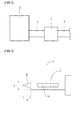
- Fig. 5 is a schematic view showing an exhaust gas purification device of one embodiment according to the present invention.
- the exhaust gas purification device 1 is connected to a source 2 of exhaust gases through a pipe 3, so that gases discharged from the source 2 of exhaust gases pass through the pipe 3 and are sent to the exhaust gas purification device 1. After the exhaust gases are purified in the exhaust gas purification device 1, the purified gases are discharged through a pipe 4.
- Examples of the source 2 of exhaust gases include internal combustion engines, such as diesel engines and gasoline engines.
- Examples of the exhaust gas purification device of the present invention include those equipped with an exhaust gas purification filter of the present invention.
- supports can be used as the support of the exhaust gas purification filter without particular limitation so long as they have a filtration function.
- An example of the support is a honeycomb filter.
- a wall-flow honeycomb filter made of ceramic is preferably used.
- the materials for the support preferably used include silicon carbide, cordierite, mullite, alumina, and aluminum titanate.
- the wall-flow honeycomb filter no particular limitation is placed on the number of cells and the wall thickness.
- the cell wall preferably has pores with a long diameter of about 1 to 50 ⁇ m.
- the exhaust gas purification filter of the present invention includes a support and the exhaust gas purification catalyst supported on the support and can be used by supporting the exhaust gas purification catalyst on the surface of the support, the wall surfaces of the cells, the pores, and so on.
- Examples of the method for supporting the exhaust gas purification catalyst on the support include the immersion method and the spraying method.
- the exhaust gas purification catalyst can be supported on the support by preparing a slurry from the exhaust gas purification catalyst together with a binder, a dispersant, and so on, immersing the support into the prepared catalyst slurry, picking up the support from the slurry, drying it, and then removing organic components by firing at 300 to 800°C.
- the exhaust gas purification catalyst of the present invention since the exhaust gas purification catalyst of the present invention has high thermal resistance and therefore low aggression to the support, it can be supported on the support by mixing ceramic particles as a source material of the support with the exhaust gas purification catalyst of the present invention, a pore-forming agent, and so on, forming the mixture into the shape of the support, and then firing the formed shape.
- the exhaust gas purification catalyst of the present invention since the exhaust gas purification catalyst of the present invention has high thermal resistance and therefore low aggression to the support, the amount thereof supported on the support can be appropriately selected depending upon the desired filtering capability.
- the exhaust gas purification catalyst of the present invention can be used within the range of 1 to 100 parts by mass, preferably 1 to 50 parts by mass, and more preferably 1 to 30 parts by mass, relative to 100 parts by mass of the support.
- the exhaust gas purification catalyst of the present invention can combust PM at low temperatures, has high thermal resistance, and therefore has low aggression to the support. For this reason, the exhaust gas purification filter with the exhaust gas purification catalyst of the present invention supported thereon has a high combustion efficiency of PM, can prevent deterioration of the catalyst owing to high temperatures during abnormal combustion, and can achieve a highly reliable exhaust gas purification filter having excellent durability.
- the exhaust gas purification filter of the present invention because of its excellent features, can be suitably used as a filter for a diesel engine (DPF), a filter for a gasoline engine or the like for the purpose of removing PM contained in exhaust gases discharged from such an internal combustion engine.
- Na 2 ZrO 3 obtained in Comparative Example 1 and Na 2 SiO 3 obtained in Comparative Example 3 were mixed in equal proportions of 50% by mass to produce a mixture.
- Each of the obtained exhaust gas purification catalysts was ground in a mortar and 5% by mass carbon black (TOKABLACK #7100F manufactured by Tokai Carbon Co., Ltd.) was added as pseudo-PM to the ground product and mixed therewith in the mortar.
- TOKABLACK #7100F manufactured by Tokai Carbon Co., Ltd. was added as pseudo-PM to the ground product and mixed therewith in the mortar.
- the obtained mixtures were measured for TG/DTA using a thermal analyzer (EXSTAR6000 TG/DTA6300 manufactured by Seiko Instruments Inc.) under the conditions of a temperature rise of 10°C/min, an atmosphere of dry air at a rate of 200 ml/min, and a sample amount of 10 mg to determine the temperature at which the rate of mass reduction due to combustion of the carbon black reaches a maximum (the peak temperature of the DTG curve).
- the results are shown in Table 1.
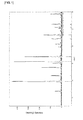
- Fig. 1 shows an X-ray diffraction pattern chart of the catalyst Na 4 Zr 2 Si 3 O 12 obtained in Example 4.
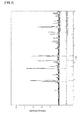
- Fig. 2 shows an X-ray diffraction pattern chart of the fired product obtained by firing the mixture of the catalyst in Example 4 and aluminum titanate under the above conditions.
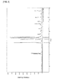
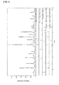
- Fig. 3 shows an X-ray diffraction pattern chart of NaAlO 2 obtained in Comparative Example 5 and Fig. 4 shows an X-ray diffraction pattern chart of the fired product obtained by firing the mixture of NaAlO 2 and aluminum titanate under the above conditions.
- the fired product of the mixture of the solid of Comparative Example 5 and aluminum titanate showed not only X-ray diffraction peaks of NaAlO 2 and aluminum titanate but also X-ray diffraction peaks of compounds assumed to have been produced by decomposition of the above NaAlO 2 and aluminum titanate.
- Compounded into 10 parts by mass of each of the obtained exhaust gas purification catalysts were 90 parts by mass of aluminum titanate (manufactured by MARUSU GLAZE, Co., Ltd.), 20 parts by mass of graphite, 10 parts by mass of methylcellulose, and 0.5 parts by mass of fatty acid soap. A suitable amount of water was also added to the mixture and the mixture was then kneaded to obtain an extrudable clay.
- the obtained clay was extruded and formed into a honeycomb structure by an extruder to obtain a green body.
- the cell density of the die was 300 cells/inch 2 (46.5 cells/cm 2 ) and the partition thickness was 500 ⁇ m.
- the obtained green body was evaluated for hardness using a hardness tester (CLAY HARDNESS TESTER manufactured by NGK Insulators, Ltd.).
- Fig. 6 is a schematic view showing the hardness tester used here.
- the hardness tester 5 includes an unshown spring contained in a cylindrical body 7 and a conical needle 6 provided at a distal end of the spring.
- the height X of the needle 6 is 35 mm and the diameter Y thereof is 10 mm.
- the spring constant of the spring contained in the cylindrical body 7 is 245 N/mm.
- the cylindrical body 7 is provided with a scale 7a, so that the amount of movement of the conical needle 6 can be read from the scale 7a.
- the needle 6 of the hardness tester 5 was inserted into the green body to a predetermined position and at that time the load was measured by reading it from the scale 7a.
- the value read for load from the hardness tester 5 was taken as "Hardness".
- the hardness refers to the yield strength of material against a needle indenter; the smaller the resistance of material to the indenter, the weaker the material.
- Examples 1 to 9 according to the present invention exhibit low PM combustion temperature and high thermal resistance. Furthermore, Examples 1 to 9 exhibit high hardness and therefore can be seen to have less effect on the green bodies.
- Compounded into 30 parts by mass of the exhaust gas purification catalyst obtained in Example 4 were 70 parts by mass of aluminum titanate (manufactured by MARUSU GLAZE, Co., Ltd.), 20 parts by mass of graphite, 10 parts by mass of methylcellulose, and 0.5 parts by mass of fatty acid soap. A suitable amount of water was also added to the mixture and the mixture was then kneaded to obtain an extrudable clay.
- the obtained clay was extruded and formed into a honeycomb structure by an extruder to obtain a green body.
- the cell density of the die was 300 cells/inch 2 (46.5 cells/cm 2 ) and the partition thickness was 300 ⁇ m.
- a slurry was prepared the solid of which was substantially made of aluminum titanate (manufactured by MARUSU GLAZE, Co., Ltd.) and the exhaust gas purification catalyst obtained in Example 4 and to which an additive, such as a viscosity modifier, was added.
- the slurry was applied in some of the cells of the green body having a honeycomb structure to seal some of the cell openings so that the open cells and sealed cells of the honeycomb structure gave a checkered pattern.
- Fig. 7 is a perspective view showing the resultant exhaust gas purification filter 10.
- the arrow A represents the direction of extrusion.
- the resultant exhaust gas purification filter was subjected to a regeneration test in the following manner.
- the initial weight of the exhaust gas purification filter was previously measured and an oxidation catalyst (DOC) and the exhaust gas purification filter were placed in this order in an exhaust line of a diesel engine. After the placement, the diesel engine was started, a specific amount (approximately 8 g/L) of PM was deposited on the filter under the operating condition in which the exhaust temperature became low, the sintered honeycomb body was then removed from the exhaust line, and the weight of PM deposited was measured.
- DOC oxidation catalyst
- the exhaust gas purification filter having PM deposited thereon was placed in an exhaust line for pseudo-gases.
- pseudo-exhaust gases having a composition shown in Table 2 were allowed to flow through the filter to reach a space velocity (SV value) of 20000/h, the exhaust temperature was raised to 540°C, and the regeneration test was then started. For 30 minutes after the exhaust temperature reached 540°C, the filter was held at a temperature of 540°C ⁇ 10°C. After a lapse of 30 minutes, the total amount of the pseudo-exhaust gases was changed to nitrogen gas. After the exhaust temperature dropped to room temperature, the exhaust gas purification filter was removed again and its weight reduction (i.e., the weight of PM combusted) was measured. The results are shown in Table 2.
- Regeneration rate % 100 - weight of PM deposited g - weight of PM combusted g / weight of PM deposited g ⁇ 100.
- Regeneration rate % 100 - weight of PM deposited g - weight of PM combusted g / weight of PM deposited g ⁇ 100.
Landscapes
- Chemical & Material Sciences (AREA)
- Engineering & Computer Science (AREA)
- Chemical Kinetics & Catalysis (AREA)
- Materials Engineering (AREA)
- Organic Chemistry (AREA)
- Combustion & Propulsion (AREA)
- Environmental & Geological Engineering (AREA)
- Biomedical Technology (AREA)
- Health & Medical Sciences (AREA)
- Analytical Chemistry (AREA)
- General Chemical & Material Sciences (AREA)
- Oil, Petroleum & Natural Gas (AREA)
- General Engineering & Computer Science (AREA)
- Mechanical Engineering (AREA)
- Catalysts (AREA)
- Exhaust Gas Treatment By Means Of Catalyst (AREA)
- Processes For Solid Components From Exhaust (AREA)
Abstract
Description
- This invention relates to exhaust gas purification catalysts for combusting particulate matter (PM) contained in exhaust gases, exhaust gas purification devices and filters, and methods for producing the catalysts.
- Conventional methods for removing PM contained in exhaust gases discharged from an internal combustion engine, such as a diesel engine, include a method of placing a honeycomb filter made of a heat-resistance ceramic, such as silicon carbide, aluminum titanate or cordierite, in an exhaust system, collecting PM on the honeycomb filter to remove PM from the exhaust gases, and then, upon deposition of a predetermined amount of PM on the honeycomb filter, applying heat to the honeycomb filter to decompose PM by combustion. However, the combustion temperature of PM is as high as 550 to 650°C, which presents a problem of a large size of the entire exhaust gas purification device and a problem of high energy cost for heat application.
- As a solution to them, a honeycomb filter is used in which a catalyst for combusting PM is supported on its surface. With this method, the combustion temperature of PM can be reduced by catalysis to reduce the energy taken to apply heat to the honeycomb filter.
- Precious metals, such as platinum, are known as such catalysts but the amount of production thereof is extremely small, which carries a risk of significant variations in supply-demand balance and price. Alternatively, silicates, aluminates, and zirconates of alkali metals are proposed as exhaust gas catalysts in Patent Literature 1. However, these catalysts have a problem in that they may react with the support of the exhaust gas purification filter to lose their catalytic activity or deteriorate the support of the exhaust gas purification filter.
- Meanwhile, exhaust gas catalysts for motor vehicles are required to have high thermal resistance because they may be exposed to high-temperature gases reaching even 1000°C depending upon running conditions of motor vehicles.
- Patent Literature 1:
JP-A-H10-118490 - An object of the present invention is to provide an exhaust gas purification catalyst having high catalytic activity enabling combustion of PM at low temperatures and excellent thermal resistance, an exhaust gas purification device and filter having high combustion efficiency of PM and excellent durability, and a method for producing the catalyst.
- The inventors conducted intensive studies to solve the above problems and thus found that an exhaust gas purification catalyst containing composite oxide particles has high catalytic activity enabling combustion of PM at low temperatures and excellent thermal resistance. Based on this founding, the inventors further conducted studies and finally completed the present invention.
- Specifically, the present invention provides the following exhaust gas purification catalyst, exhaust gas purification device and filter, and method for producing the catalyst.
- Aspect 1: An exhaust gas purification catalyst being composite oxide particles containing at least one alkali metal, Si, and Zr.
- Aspect 2: The exhaust gas purification catalyst according to aspect 1, having an ionic conductivity of 0.5×10⁻⁶ mS/cm or more.
- Aspect 3: The exhaust gas purification catalyst according to
aspect 1 or 2, wherein the content rates of the metals, exclusive of oxygen, in the composite oxide are 30 to 60% by mole alkali metal, 20 to 60% by mole Si, and 10 to 40% by mole Zr. - Aspect 4: The exhaust gas purification catalyst according to
aspect 1 or 2, wherein the composite oxide is represented by the following general formula:
A2XZrXSiYO3X+2Y
(where A represents at least one alkali metal, X represents a positive real number satisfying 1≤X≤2, and Y represents a positive real number satisfying 1≤Y≤6.) - Aspect 5: An exhaust gas purification device including the exhaust gas purification catalyst according to any one of aspects 1 to 4.
- Aspect 6: An exhaust gas purification filter, including a support and the exhaust gas purification catalyst according to any one of aspects 1 to 4, the exhaust gas purification catalyst being supported on the support.
- Aspect 7: The exhaust gas purification filter according to
aspect 6, wherein the support is a honeycomb filter. - Aspect 8: A method for producing the exhaust gas purification catalyst according to any one of aspects 1 to 4, wherein the exhaust gas purification catalyst is produced by firing a mixture containing at least one alkali metal salt, a silicon source, and a zirconium source.
- The present invention can provide an exhaust gas purification catalyst having high catalytic activity enabling combustion of PM at low temperatures and excellent thermal resistance and provide an exhaust gas purification device and filter having high combustion efficiency of PM and excellent durability.
-
- [
Fig. 1] Fig. 1 is a graph showing an X-ray diffraction pattern chart of a catalyst obtained in Example 4. - [
Fig. 2] Fig. 2 is a graph showing an X-ray diffraction pattern chart of a fired mixture of the catalyst in Example 4 and aluminum titanate. - [
Fig. 3] Fig. 3 is a graph showing an X-ray diffraction pattern chart of a catalyst obtained in Comparative Example 5. - [
Fig. 4] Fig. 4 is a graph showing an X-ray diffraction pattern chart of a fired mixture of the catalyst in Comparative Example 5 and aluminum titanate. - [
Fig. 5] Fig. 5 is a schematic view showing an exhaust gas purification device of one embodiment according to the present invention. - [
Fig. 6] Fig. 6 is a schematic view showing a hardness tester. - [
Fig. 7] Fig. 7 is a schematic perspective view showing a honeycomb structure produced in an example according to the present invention. - Hereinafter, a description will be given of an example of a preferred embodiment for working of the present invention. However, the following embodiment is simply illustrative. The present invention is not at all intended to be limited to the following embodiment.
- An exhaust gas purification catalyst of the present invention is composite oxide particles and the composite oxide particles contain at least one alkali metal, Si, and Zr.
- The exhaust gas purification catalyst of the present invention has an ionic conductivity of preferably 0.5×10⁻⁶ mS/cm or more, more preferably 0.5×10⁻⁶ to 10.0×10⁻⁶ mS/cm. When the ionic conductivity is 0.5×10⁻⁶ mS/cm or more, the catalytic activity becomes high and thus the combustion efficiency of PM can be improved.
- The exhaust gas purification catalyst of the present invention is preferably composite oxide particles containing 30 to 60% by mole alkali metal, 10 to 40% by mole Zr, and 20 to 60% by mole Si and more preferably composite oxide particles containing 33 to 50% by mole alkali metal, 16 to 25% by mole Zr, and 25 to 51% by mole Si. Note that these values of % by mole are the content rates of the metals, exclusive of oxygen, in the composite oxide and values when the total content rate of all the metals therein is 100% by mole.
- The composite oxide particles in the preferred embodiment, more specifically, can be represented by a general formula of A2XZrXSiYO3X+2Y. In the formula, A represents at least one or more alkali metals. X represents a positive real number satisfying 1≤X≤2 and Y represents a positive real number satisfying 1≤Y≤6. More preferably, Y is a positive real number satisfying 1≤Y≤3.
- Examples of the alkali metal include Li, Na, K, Rb, Cs, and Fr. Preferred among them are Li, Na, K, and Cs because of their economic advantage.
- Composite oxides which can be taken as examples of the exhaust gas purification catalyst of the present invention include Li2ZrSiO5, Na2ZrSiO5, Na4Zr2Si3O12, Na2ZrSi2O7, Na2ZrSi3O9, K2ZrSiO5, K2ZrSi2O7, K2ZrSi3O9, Cs4Zr2Si3O12, Cs2ZrSi2O7, and Cs2ZrSi3O9.
- The exhaust gas purification catalyst of the present invention can contain other elements as long as its excellent characteristics are not impaired. Other elements which can be taken as examples include Fe, Nb, Ti, Al, Ce, Ca, Mg, Sr, Ba, Y, Mn, and P. The content rate of other elements is preferably within the range of 0.1 to 30.0% by mole.
- Although no particular limitation is placed on the method for producing composite oxide particles used in the present invention, the composite oxide particles can be produced, for example, by firing a mixture containing at least one alkali metal salt, a silicon source, and a zirconium source.
- The mixture ratio of alkali metal salt to zirconium source to silicon source can be appropriately selected depending upon the desired composition of the composite oxide particles but is preferably a ratio of 20 to 50% by mole alkali metal salt to 10 to 50% by mole zirconium source to 20 to 70% by mole silicon source and more preferably a ratio of 20 to 35% by mole alkali metal salt to 20 to 35% by mole zirconium source to 30 to 60% by mole silicon source.
- The alkali metal salts include alkali metal carbonates; alkali metal hydrogen carbonates; alkali metal hydroxides; alkali metal organic acid salts, such as alkali metal acetates; alkali metal sulfates; and alkali metal nitrates, but the preferred alkali metal salts are alkali metal carbonates.
- Although no particular limitation is placed on the silicon source so long as it is a source material containing elemental silicon and not interfering with the production of the composite oxide particles of the present invention by firing, examples include compounds which can be led to silicon oxide by firing in air. Examples of such compounds include silicon oxide and silicon and the preferred is silicon oxide.
- Although no particular limitation is placed on the zirconium source so long as it is a source material containing elemental zirconium and not interfering with the production of the composite oxide particles of the present invention by firing, examples include compounds which can be led to zirconium oxide by firing in air. Examples of such compounds include zirconium oxide, zirconium carbonate hydrate, and zirconium sulfate hydrate and the preferred is zirconium oxide.
- The temperature for firing the mixture can be appropriately selected depending upon the desired composition of the composite oxide particles but is preferably within the range of 900 to 1300°C.
- The time for firing the mixture can be appropriately selected depending upon the desired composition of the composite oxide particles but is preferably 4 to 24 hours.
- The exhaust gas purification catalyst of the present invention can combust at low temperatures PM contained in exhaust gases discharged from internal combustion engines and the like because of high catalytic activity of alkali metal and can further improve the combustion efficiency of PM because of its high ionic conductivity. Inclusion of Si and Zr in its crystal structure can improve the thermal resistance. In addition, Si and Zr in the crystal structure can be considered to reduce the elution of alkali metal and thus prevent deterioration of the support.
- An exhaust gas purification device of the present invention includes the aforementioned exhaust gas purification catalyst of the present invention. Therefore, the exhaust gas purification device can combust PM at low temperatures, can improve the combustion efficiency of PM, and has high thermal resistance.
-
Fig. 5 is a schematic view showing an exhaust gas purification device of one embodiment according to the present invention. The exhaust gas purification device 1 is connected to asource 2 of exhaust gases through apipe 3, so that gases discharged from thesource 2 of exhaust gases pass through thepipe 3 and are sent to the exhaust gas purification device 1. After the exhaust gases are purified in the exhaust gas purification device 1, the purified gases are discharged through apipe 4. Examples of thesource 2 of exhaust gases include internal combustion engines, such as diesel engines and gasoline engines. - Examples of the exhaust gas purification device of the present invention include those equipped with an exhaust gas purification filter of the present invention.
- Conventionally known supports can be used as the support of the exhaust gas purification filter without particular limitation so long as they have a filtration function. An example of the support is a honeycomb filter. Specifically, a wall-flow honeycomb filter made of ceramic is preferably used. The materials for the support preferably used include silicon carbide, cordierite, mullite, alumina, and aluminum titanate. In the case of the wall-flow honeycomb filter, no particular limitation is placed on the number of cells and the wall thickness. Although no particular limitation is placed on the type of the cell wall surface so long as it is a porous wall, the cell wall preferably has pores with a long diameter of about 1 to 50 µm.
- The exhaust gas purification filter of the present invention includes a support and the exhaust gas purification catalyst supported on the support and can be used by supporting the exhaust gas purification catalyst on the surface of the support, the wall surfaces of the cells, the pores, and so on.
- Examples of the method for supporting the exhaust gas purification catalyst on the support include the immersion method and the spraying method. For example, in the immersion method, the exhaust gas purification catalyst can be supported on the support by preparing a slurry from the exhaust gas purification catalyst together with a binder, a dispersant, and so on, immersing the support into the prepared catalyst slurry, picking up the support from the slurry, drying it, and then removing organic components by firing at 300 to 800°C. Alternatively, since the exhaust gas purification catalyst of the present invention has high thermal resistance and therefore low aggression to the support, it can be supported on the support by mixing ceramic particles as a source material of the support with the exhaust gas purification catalyst of the present invention, a pore-forming agent, and so on, forming the mixture into the shape of the support, and then firing the formed shape.
- In addition, since the exhaust gas purification catalyst of the present invention has high thermal resistance and therefore low aggression to the support, the amount thereof supported on the support can be appropriately selected depending upon the desired filtering capability. For example, the exhaust gas purification catalyst of the present invention can be used within the range of 1 to 100 parts by mass, preferably 1 to 50 parts by mass, and more preferably 1 to 30 parts by mass, relative to 100 parts by mass of the support.
- The exhaust gas purification catalyst of the present invention can combust PM at low temperatures, has high thermal resistance, and therefore has low aggression to the support. For this reason, the exhaust gas purification filter with the exhaust gas purification catalyst of the present invention supported thereon has a high combustion efficiency of PM, can prevent deterioration of the catalyst owing to high temperatures during abnormal combustion, and can achieve a highly reliable exhaust gas purification filter having excellent durability. The exhaust gas purification filter of the present invention, because of its excellent features, can be suitably used as a filter for a diesel engine (DPF), a filter for a gasoline engine or the like for the purpose of removing PM contained in exhaust gases discharged from such an internal combustion engine.
- The present invention will be described below in further detail with reference to specific examples. The present invention is not at all limited by the following examples and modifications and variations may be appropriately made therein without changing the gist of the invention.
- An amount of 36.6 parts by mass of sodium carbonate, 42.6 parts by mass of zirconium oxide, and 20.8 parts by mass of silicon oxide were mixed and the mixture was fired at 1200°C for four hours. The resultant particulate solid was confirmed to be single-phase Na2ZrSiO5 by X-ray diffractometry.
- An amount of 30.3 parts by mass of sodium carbonate, 35.3 parts by mass of zirconium oxide, and 34.4 parts by mass of silicon oxide were mixed and the mixture was fired at 1200°C for four hours. The resultant particulate solid was confirmed to be single-phase Na2ZrSi2O7 by X-ray diffractometry.
- An amount of 25.9 parts by mass of sodium carbonate, 30.1 parts by mass of zirconium oxide, and 44.0 parts by mass of silicon oxide were mixed and the mixture was fired at 1200°C for four hours. The resultant particulate solid was confirmed to be single-phase Na2ZrSi3O9 by X-ray diffractometry.
- An amount of 33.2 parts by mass of sodium carbonate, 38.6 parts by mass of zirconium oxide, and 28.2 parts by mass of silicon oxide were mixed and the mixture was fired at 1200°C for four hours. The resultant particulate solid was confirmed to be single-phase Na4Zr2Si3O12 by X-ray diffractometry.
- An amount of 43.0 parts by mass of potassium carbonate, 38.3 parts by mass of zirconium oxide, and 18.7 parts by mass of silicon oxide were mixed and the mixture was fired at 1200°C for four hours. The resultant particulate solid was confirmed to be single-phase K2ZrSiO5 by X-ray diffractometry.
- An amount of 36.2 parts by mass of potassium carbonate, 32.3 parts by mass of zirconium oxide, and 31.5 parts by mass of silicon oxide were mixed and the mixture was fired at 1200°C for four hours. The resultant particulate solid was confirmed to be single-phase K2ZrSi2O7 by X-ray diffractometry.
- An amount of 31.3 parts by mass of potassium carbonate, 27.9 parts by mass of zirconium oxide, and 40.8 parts by mass of silicon oxide were mixed and the mixture was fired at 1200°C for four hours. The resultant particulate solid was confirmed to be single-phase K2ZrSi3O9 by X-ray diffractometry.
- An amount of 51.8 parts by mass of cesium carbonate, 19.6 parts by mass of zirconium oxide, and 28.6 parts by mass of silicon oxide were mixed and the mixture was fired at 1200°C for four hours. The resultant particulate solid was confirmed to be single-phase Cs2ZrSi3O9 by X-ray diffractometry.
- An amount of 28.7 parts by mass of lithium carbonate, 47.9 parts by mass of zirconium oxide, and 23.4 parts by mass of silicon oxide were mixed and the mixture was fired at 1200°C for four hours. The resultant particulate solid was confirmed to be single-phase Li2ZrSiO5 by X-ray diffractometry.
- An amount of 46.2 parts by mass of sodium carbonate and 53.8 parts by mass of zirconium oxide were mixed and the mixture was fired at 1200°C for four hours. The resultant particulate solid was confirmed to be single-phase Na2ZrO3 by X-ray diffractometry.
- An amount of 52.9 parts by mass of potassium carbonate and 47.1 parts by mass of zirconium oxide were mixed and the mixture was fired at 1200°C for four hours. The resultant particulate solid was confirmed to be single-phase K2ZrO3 by X-ray diffractometry.
- An amount of 63.8 parts by mass of sodium carbonate and 36.2 parts by mass of silicon oxide were mixed and the mixture was fired at 1200°C for four hours. The resultant viscous oily matter was confirmed to be single-phase Na2SiO3 by X-ray diffractometry.
- Na2ZrO3 obtained in Comparative Example 1 and Na2SiO3 obtained in Comparative Example 3 were mixed in equal proportions of 50% by mass to produce a mixture.
- An amount of 51.0 parts by mass of sodium carbonate and 49.0 parts by mass of aluminum oxide were mixed and the mixture was fired at 1200°C for four hours. The resultant particulate solid was confirmed to be single-phase NaAlO2 by X-ray diffractometry.
- An amount of 57.5 parts by mass of potassium carbonate and 42.5 parts by mass of aluminum oxide were mixed and the mixture was fired at 1200°C for four hours. The resultant particulate solid was confirmed to be single-phase KAlO2 by X-ray diffractometry.
- An amount of 32.3 parts by mass of sodium carbonate, 31.1 parts by mass of aluminum oxide, and 36.6 parts by mass of silicon oxide were mixed and the mixture was fired at 1200°C for four hours. The resultant particulate solid was confirmed to be single-phase NaAlSiO4 by X-ray diffractometry.
- An amount of 38.4 parts by mass of potassium carbonate, 28.3 parts by mass of aluminum oxide, and 33.3 parts by mass of silicon oxide were mixed and the mixture was fired at 1200°C for four hours. The resultant particulate solid was confirmed to be single-phase KAlSiO4 by X-ray diffractometry.
- An amount of 10 g of each of the obtained exhaust gas purification catalysts was produced into a compact and the compact was fired at 1200°C for four hours. A piece of aluminum foil was pressure bonded to the obtained sintered body with an electrically conductive paste (Varniphite T-602 manufactured by Nippon Graphite Industries, Co., Ltd.) to form an electrode and an aluminum lead was pressure bonded to the electrode to obtain a measurement sample. The obtained measurement samples were measured for ionic conductivity using an impedance analyzer (IviumStat manufactured by Ivium Technologies). The results are shown in Table 1. Note that since Comparative Example 3 was a viscous oily matter, measurement samples appropriate to the measurement could not be produced from Comparative Examples 3 and 4.
- Each of the obtained exhaust gas purification catalysts was ground in a mortar and 5% by mass carbon black (TOKABLACK #7100F manufactured by Tokai Carbon Co., Ltd.) was added as pseudo-PM to the ground product and mixed therewith in the mortar.
- The obtained mixtures were measured for TG/DTA using a thermal analyzer (EXSTAR6000 TG/DTA6300 manufactured by Seiko Instruments Inc.) under the conditions of a temperature rise of 10°C/min, an atmosphere of dry air at a rate of 200 ml/min, and a sample amount of 10 mg to determine the temperature at which the rate of mass reduction due to combustion of the carbon black reaches a maximum (the peak temperature of the DTG curve). The results are shown in Table 1.
- An amount of 90 parts by mass of aluminum titanate (manufactured by MARUSU GLAZE, Co., Ltd.) was added to 10 parts by mass of each of the obtained exhaust gas purification catalysts and mixed therewith in a mortar. The obtained mixtures were fired at 1000°C for four hours. The mixtures having showed no change in X-ray diffraction peak compared to before firing were indicated by "o" and the mixtures having showed any change in X-ray diffraction peak compared to before firing were indicated by "x". The results are shown in Table 1.
-
Fig. 1 shows an X-ray diffraction pattern chart of the catalyst Na4Zr2Si3O12 obtained in Example 4. -
Fig. 2 shows an X-ray diffraction pattern chart of the fired product obtained by firing the mixture of the catalyst in Example 4 and aluminum titanate under the above conditions. -
Fig. 3 shows an X-ray diffraction pattern chart of NaAlO2 obtained in Comparative Example 5 andFig. 4 shows an X-ray diffraction pattern chart of the fired product obtained by firing the mixture of NaAlO2 and aluminum titanate under the above conditions. - As shown in
Fig. 2 , when the mixture of the catalyst in Example 4 and aluminum titanate was fired, the fired product showed only X-ray diffraction peaks of the catalyst and aluminum titanate and hardly showed other peaks. - In contrast, the fired product of the mixture of the solid of Comparative Example 5 and aluminum titanate, as shown in
Fig. 4 , showed not only X-ray diffraction peaks of NaAlO2 and aluminum titanate but also X-ray diffraction peaks of compounds assumed to have been produced by decomposition of the above NaAlO2 and aluminum titanate. - Compounded into 10 parts by mass of each of the obtained exhaust gas purification catalysts were 90 parts by mass of aluminum titanate (manufactured by MARUSU GLAZE, Co., Ltd.), 20 parts by mass of graphite, 10 parts by mass of methylcellulose, and 0.5 parts by mass of fatty acid soap. A suitable amount of water was also added to the mixture and the mixture was then kneaded to obtain an extrudable clay.
- The obtained clay was extruded and formed into a honeycomb structure by an extruder to obtain a green body. The cell density of the die was 300 cells/inch2 (46.5 cells/cm2) and the partition thickness was 500 µm.
- The obtained green body was evaluated for hardness using a hardness tester (CLAY HARDNESS TESTER manufactured by NGK Insulators, Ltd.).
-
Fig. 6 is a schematic view showing the hardness tester used here. Thehardness tester 5 includes an unshown spring contained in acylindrical body 7 and aconical needle 6 provided at a distal end of the spring. The height X of theneedle 6 is 35 mm and the diameter Y thereof is 10 mm. The spring constant of the spring contained in thecylindrical body 7 is 245 N/mm. Thecylindrical body 7 is provided with ascale 7a, so that the amount of movement of theconical needle 6 can be read from thescale 7a. - The
needle 6 of thehardness tester 5 was inserted into the green body to a predetermined position and at that time the load was measured by reading it from thescale 7a. In the present invention, the value read for load from thehardness tester 5 was taken as "Hardness". The hardness refers to the yield strength of material against a needle indenter; the smaller the resistance of material to the indenter, the weaker the material. - The actual measurement was made by inserting the
hardness tester 5 into a flat portion of the green body to reach the root of theneedle 6 in five seconds and recording the value read from thehardness tester 5 at that time (where the measurement value of thehardness tester 5 is within the range of 0 to 20). The results are shown in Table 1.[Table 1] Catalyst Composition Ionic Conductivity (mS/cm) PM Combustion Temperature (°C) Thermal Resistance Hardness Ex. 1 Na2ZrSiO5 0.9×10⁻⁶ 480 ○ 9 Ex. 2 Na2ZrSi2O7 1.0×10⁻⁶ 486 ○ 11 Ex. 3 Na2ZrSi3O9 1.0×10⁻⁶ 502 ○ 12 Ex. 4 Na4Zr2Si3O12 1.3×10⁻⁶ 483 ○ 10 Ex. 5 K2ZrSiO5 0.8×10⁻⁶ 461 ○ 9 Ex. 6 K2ZrSi2O7 0.9×10⁻⁶ 475 ○ 9 Ex. 7 K2ZrSi3O9 0.8×10⁻⁶ 489 ○ 10 Ex. 8 Cs2ZrSi3O9 0.5×10⁻⁶ 479 ○ 9 Ex. 9 Li2ZrSiO5 0.6×10⁻⁶ 502 ○ 9 Comp.Ex.1 Na2ZrO3 0.7×10⁻⁶ 492 × 6 Comp.Ex.2 K2ZrO3 0.5×10⁻⁶ 483 × 5 Comp.Ex.3 Na2SiO3 - 469 × 2 Comp.Ex.4 Na2ZrO3+Na2SiO3 - 479 × 3 Comp.Ex.5 NaAlO2 <1.0×10⁻⁸ 518 × 2 Comp.Ex.6 KAlO2 <1.0×10⁻⁸ 512 × 2 Comp.Ex.7 NaAlSiO4 <1.0×10⁻⁸ 562 ○ 11 Comp.Ex.8 KAlSiO4 <1.0×10⁻⁸ 558 ○ 10 - As shown in Table 1, Examples 1 to 9 according to the present invention exhibit low PM combustion temperature and high thermal resistance. Furthermore, Examples 1 to 9 exhibit high hardness and therefore can be seen to have less effect on the green bodies.
- Compounded into 30 parts by mass of the exhaust gas purification catalyst obtained in Example 4 were 70 parts by mass of aluminum titanate (manufactured by MARUSU GLAZE, Co., Ltd.), 20 parts by mass of graphite, 10 parts by mass of methylcellulose, and 0.5 parts by mass of fatty acid soap. A suitable amount of water was also added to the mixture and the mixture was then kneaded to obtain an extrudable clay.
- The obtained clay was extruded and formed into a honeycomb structure by an extruder to obtain a green body. The cell density of the die was 300 cells/inch2 (46.5 cells/cm2) and the partition thickness was 300 µm.
- A slurry was prepared the solid of which was substantially made of aluminum titanate (manufactured by MARUSU GLAZE, Co., Ltd.) and the exhaust gas purification catalyst obtained in Example 4 and to which an additive, such as a viscosity modifier, was added.
- The slurry was applied in some of the cells of the green body having a honeycomb structure to seal some of the cell openings so that the open cells and sealed cells of the honeycomb structure gave a checkered pattern.
- The green body with some of the cells sealed was fired by holding it at 600°C for 10 hours, then raising the temperature to 1000°C at a rate of 25°C/h, and holding it at 1000°C for 10 hours, resulting in an exhaust gas purification filter.
Fig. 7 is a perspective view showing the resultant exhaustgas purification filter 10. InFig. 7 , the arrow A represents the direction of extrusion. - For evaluations, the resultant exhaust gas purification filter was subjected to a regeneration test in the following manner.
- The initial weight of the exhaust gas purification filter was previously measured and an oxidation catalyst (DOC) and the exhaust gas purification filter were placed in this order in an exhaust line of a diesel engine. After the placement, the diesel engine was started, a specific amount (approximately 8 g/L) of PM was deposited on the filter under the operating condition in which the exhaust temperature became low, the sintered honeycomb body was then removed from the exhaust line, and the weight of PM deposited was measured.
- Next, the exhaust gas purification filter having PM deposited thereon was placed in an exhaust line for pseudo-gases. After the placement, pseudo-exhaust gases having a composition shown in Table 2 were allowed to flow through the filter to reach a space velocity (SV value) of 20000/h, the exhaust temperature was raised to 540°C, and the regeneration test was then started. For 30 minutes after the exhaust temperature reached 540°C, the filter was held at a temperature of 540°C ± 10°C. After a lapse of 30 minutes, the total amount of the pseudo-exhaust gases was changed to nitrogen gas. After the exhaust temperature dropped to room temperature, the exhaust gas purification filter was removed again and its weight reduction (i.e., the weight of PM combusted) was measured. The results are shown in Table 2.
- The regeneration rate was obtained from the following calculation formula:

[Table 2] Pseudo-Exhaust Gas Composition Regeneration Rate O2 CO CO2 NO NO2 N2 Evaluation 1 10.00% 0.03% 5.00% 0.02% 0.02% 84.93% 80 % Evaluation 2 10.00% 0.03% 5.00% 0.00% 0.00% 84.97% 83% - Platinum-based catalysts used in conventional exhaust gas filters burn off PM using the NO2 oxidation capacity. Unlike this, the exhaust gas purification filter according to the present invention can combust PM in spite of the presence or absence of NO2 as shown in Table 2.
-
- 1
- exhaust gas purification device
- 2
- source of exhaust gases
- 3, 4
- pipe
- 5
- hardness tester
- 6
- conical needle
- 7
- cylindrical body
- 7a
- scale
- 10
- exhaust gas purification filter
- A
- direction of extrusion of green body
Claims (8)
- An exhaust gas purification catalyst being composite oxide particles containing at least one alkali metal, Si, and Zr.
- The exhaust gas purification catalyst according to claim 1, having an ionic conductivity of 0.5×10⁻⁶ mS/cm or more.
- The exhaust gas purification catalyst according to claim 1 or 2, wherein the content rates of the metals, exclusive of oxygen, in the composite oxide are 30 to 60% by mole alkali metal, 20 to 60% by mole Si, and 10 to 40% by mole Zr.
- The exhaust gas purification catalyst according to claim 1 or 2, wherein the composite oxide is represented by the following general formula:
A2XZrXSiYO3X+2Y
where A represents at least one alkali metal, X represents a positive real number satisfying 1≤X≤2, and Y represents a positive real number satisfying 1≤Y≤6. - An exhaust gas purification device comprising the exhaust gas purification catalyst according to any one of claims 1 to 4.
- An exhaust gas purification filter, including a support and the exhaust gas purification catalyst according to any one of claims 1 to 4, the exhaust gas purification catalyst being supported on the support.
- The exhaust gas purification filter according to claim 6, wherein the support is a honeycomb filter.
- A method for producing the exhaust gas purification catalyst according to any one of claims 1 to 4, wherein the exhaust gas purification catalyst is produced by firing a mixture containing at least one alkali metal salt, a silicon source, and a zirconium source.
Applications Claiming Priority (2)
| Application Number | Priority Date | Filing Date | Title |
|---|---|---|---|
| JP2012054182 | 2012-03-12 | ||
| PCT/JP2013/055279 WO2013136991A1 (en) | 2012-03-12 | 2013-02-28 | Exhaust gas purification catalyst, exhaust gas purification device and filter, and production method for said catalyst |
Publications (2)
| Publication Number | Publication Date |
|---|---|
| EP2826558A1 true EP2826558A1 (en) | 2015-01-21 |
| EP2826558A4 EP2826558A4 (en) | 2016-01-06 |
Family
ID=49160907
Family Applications (1)
| Application Number | Title | Priority Date | Filing Date |
|---|---|---|---|
| EP13760652.1A Withdrawn EP2826558A4 (en) | 2012-03-12 | 2013-02-28 | Exhaust gas purification catalyst, exhaust gas purification device and filter, and production method for said catalyst |
Country Status (6)
| Country | Link |
|---|---|
| US (2) | US20150056106A1 (en) |
| EP (1) | EP2826558A4 (en) |
| JP (1) | JP5612795B2 (en) |
| KR (1) | KR101708986B1 (en) |
| CN (1) | CN104379252B (en) |
| WO (1) | WO2013136991A1 (en) |
Cited By (1)
| Publication number | Priority date | Publication date | Assignee | Title |
|---|---|---|---|---|
| EP3322509A4 (en) * | 2015-07-15 | 2019-03-13 | University of Notre Dame | Glass catalyst compositions for improved hydrothermal durability |
Families Citing this family (2)
| Publication number | Priority date | Publication date | Assignee | Title |
|---|---|---|---|---|
| EP3159058A4 (en) | 2014-06-19 | 2018-02-14 | Otsuka Chemical Holdings Co., Ltd. | Exhaust gas purifying catalyst, exhaust gas purification device and filter, and method for producing said catalyst |
| CN104817315A (en) * | 2015-04-10 | 2015-08-05 | 中国建筑材料科学研究总院 | Sodium zirconium silicate powder and preparation method thereof |
Family Cites Families (9)
| Publication number | Priority date | Publication date | Assignee | Title |
|---|---|---|---|---|
| JP3839860B2 (en) * | 1995-09-22 | 2006-11-01 | 株式会社豊田中央研究所 | Exhaust gas purification catalyst and exhaust gas purification method |
| JP3900563B2 (en) | 1996-10-23 | 2007-04-04 | 松下電器産業株式会社 | Exhaust gas purification catalyst and exhaust gas purification filter using the same |
| JP4062806B2 (en) * | 1999-01-13 | 2008-03-19 | 株式会社日立製作所 | Exhaust gas purification method, purification catalyst and exhaust gas purification apparatus for internal combustion engine |
| JP4438114B2 (en) * | 1999-01-14 | 2010-03-24 | 株式会社日立製作所 | Exhaust gas purification method, exhaust gas purification catalyst and exhaust gas purification device for internal combustion engine |
| AU7616300A (en) * | 1999-10-05 | 2001-05-10 | Corning Incorporated | Refractory nzp-type structures and method of making and using same |
| JP4050041B2 (en) * | 2001-11-06 | 2008-02-20 | 株式会社日本触媒 | Catalyst for producing ethylene oxide, method for producing the same, and method for producing ethylene oxide using the catalyst |
| JP5054321B2 (en) * | 2006-03-28 | 2012-10-24 | 日揮触媒化成株式会社 | Dental filler, method for producing the same, and dental composite material |
| DE102007034633A1 (en) * | 2007-04-05 | 2009-01-29 | Nano-X Gmbh | Coating material with a catalytic activity and use of the coating material |
| CN100497183C (en) * | 2007-07-25 | 2009-06-10 | 濮阳濮耐高温材料(集团)股份有限公司 | Method for preparing zirconium oxide powder from zircon |
-
2013
- 2013-02-28 JP JP2014504776A patent/JP5612795B2/en not_active Expired - Fee Related
- 2013-02-28 KR KR1020147023332A patent/KR101708986B1/en active IP Right Grant
- 2013-02-28 US US14/377,434 patent/US20150056106A1/en not_active Abandoned
- 2013-02-28 EP EP13760652.1A patent/EP2826558A4/en not_active Withdrawn
- 2013-02-28 CN CN201380010191.3A patent/CN104379252B/en not_active Expired - Fee Related
- 2013-02-28 WO PCT/JP2013/055279 patent/WO2013136991A1/en active Application Filing
-
2017
- 2017-04-04 US US15/478,720 patent/US20170248049A1/en not_active Abandoned
Cited By (1)
| Publication number | Priority date | Publication date | Assignee | Title |
|---|---|---|---|---|
| EP3322509A4 (en) * | 2015-07-15 | 2019-03-13 | University of Notre Dame | Glass catalyst compositions for improved hydrothermal durability |
Also Published As
| Publication number | Publication date |
|---|---|
| CN104379252B (en) | 2017-04-19 |
| EP2826558A4 (en) | 2016-01-06 |
| JP5612795B2 (en) | 2014-10-22 |
| JPWO2013136991A1 (en) | 2015-08-03 |
| CN104379252A (en) | 2015-02-25 |
| US20150056106A1 (en) | 2015-02-26 |
| KR101708986B1 (en) | 2017-02-21 |
| US20170248049A1 (en) | 2017-08-31 |
| WO2013136991A1 (en) | 2013-09-19 |
| KR20140120348A (en) | 2014-10-13 |
Similar Documents
| Publication | Publication Date | Title |
|---|---|---|
| EP1745848B1 (en) | Honeycomb structured body and exhaust gas purifying device | |
| JP5773337B2 (en) | Oxidation catalyst and diesel particulate filter | |
| EP1967263B1 (en) | Catalytic Material And Catalyst For Purifying Exhaust Gas Component | |
| EP1703095A1 (en) | Exhaust gas purifying device and method for recovering exhaust gas purifying device | |
| EP2055366B1 (en) | Catalyst-supported particulate filter | |
| EP1685899A1 (en) | Honeycomb structure body | |
| EP2047907B1 (en) | Catalyst supported on particulate filter | |
| WO2003080219A1 (en) | Filter for exhaust gas decontamination | |
| JP5864444B2 (en) | Exhaust gas purification catalyst and exhaust gas purification catalyst structure | |
| EP2055365B1 (en) | Catalyst-supported particulate filter | |
| WO2008035652A1 (en) | Catalyst for burning carbon-containing substance, process for production of the catalyst, material having catalyst carried thereon, and process for production of the material | |
| EP3040122A1 (en) | Exhaust gas purification filter and exhaust gas purification apparatus | |
| US20170248049A1 (en) | Exhaust gas purification catalyst, exhaust gas purification device and filter, and production method for said catalyst | |
| EP1759763B1 (en) | Exhaust gas purification catalyst and catalyst-equipped diesel particulate filter | |
| EP2022554B1 (en) | Catalyst-supported particulate filter | |
| JP2013006170A (en) | Exhaust gas purifying catalyst and carrier | |
| JP5558867B2 (en) | Exhaust purification catalyst | |
| US11904298B2 (en) | Composite oxide catalyst, porous composite, and method of producing composite oxide catalyst | |
| US9999872B2 (en) | Exhaust gas purifying catalyst, exhaust gas purification device and filter, and method for producing said catalyst | |
| JP4503314B2 (en) | Exhaust gas purification catalyst | |
| EP2602022A1 (en) | Method for producing catalyst composition, catalyst composition, diesel particulate filter using same, and exhaust gas purification system | |
| JP2007069077A (en) | Catalyst for cleaning exhaust gas and diesel particulate filter with catalyst | |
| JP6463909B2 (en) | Exhaust gas purification catalyst, exhaust gas purification device and filter, and method for producing the catalyst | |
| JP2016123937A (en) | Catalyst for exhaust purification, device and filter for exhaust purification, and method for production of the catalyst | |
| JP2017213527A (en) | Production method of exhaust emission control catalyst, and exhaust emission control catalyst and exhaust emission control device |
Legal Events
| Date | Code | Title | Description |
|---|---|---|---|
| PUAI | Public reference made under article 153(3) epc to a published international application that has entered the european phase |
Free format text: ORIGINAL CODE: 0009012 |
|
| 17P | Request for examination filed |
Effective date: 20140806 |
|
| AK | Designated contracting states |
Kind code of ref document: A1 Designated state(s): AL AT BE BG CH CY CZ DE DK EE ES FI FR GB GR HR HU IE IS IT LI LT LU LV MC MK MT NL NO PL PT RO RS SE SI SK SM TR |
|
| AX | Request for extension of the european patent |
Extension state: BA ME |
|
| DAX | Request for extension of the european patent (deleted) | ||
| RA4 | Supplementary search report drawn up and despatched (corrected) |
Effective date: 20151203 |
|
| RIC1 | Information provided on ipc code assigned before grant |
Ipc: F01N 3/10 20060101ALI20151127BHEP Ipc: B01J 23/04 20060101AFI20151127BHEP Ipc: B01D 53/94 20060101ALI20151127BHEP Ipc: F01N 3/023 20060101ALI20151127BHEP Ipc: F01N 3/035 20060101ALI20151127BHEP |
|
| STAA | Information on the status of an ep patent application or granted ep patent |
Free format text: STATUS: THE APPLICATION HAS BEEN WITHDRAWN |
|
| 18W | Application withdrawn |
Effective date: 20180710 |