EP2826019B1 - Multi-modality deformable registration - Google Patents
Multi-modality deformable registration Download PDFInfo
- Publication number
- EP2826019B1 EP2826019B1 EP13723954.7A EP13723954A EP2826019B1 EP 2826019 B1 EP2826019 B1 EP 2826019B1 EP 13723954 A EP13723954 A EP 13723954A EP 2826019 B1 EP2826019 B1 EP 2826019B1
- Authority
- EP
- European Patent Office
- Prior art keywords
- deformation
- imaging
- different
- images
- mean
- Prior art date
- Legal status (The legal status is an assumption and is not a legal conclusion. Google has not performed a legal analysis and makes no representation as to the accuracy of the status listed.)
- Active
Links
- 238000003384 imaging method Methods 0.000 claims description 120
- 238000000034 method Methods 0.000 claims description 41
- 238000002595 magnetic resonance imaging Methods 0.000 claims description 34
- 239000013598 vector Substances 0.000 claims description 30
- 210000002307 prostate Anatomy 0.000 claims description 25
- 238000002604 ultrasonography Methods 0.000 claims description 20
- 230000009466 transformation Effects 0.000 claims description 12
- 239000011159 matrix material Substances 0.000 claims description 10
- 239000000523 sample Substances 0.000 claims description 9
- 238000000513 principal component analysis Methods 0.000 claims description 8
- 238000012285 ultrasound imaging Methods 0.000 claims description 7
- 238000004590 computer program Methods 0.000 claims description 6
- 238000012545 processing Methods 0.000 description 8
- 238000001574 biopsy Methods 0.000 description 7
- 238000012549 training Methods 0.000 description 7
- 238000010586 diagram Methods 0.000 description 6
- 238000006073 displacement reaction Methods 0.000 description 5
- 230000004927 fusion Effects 0.000 description 5
- 230000003287 optical effect Effects 0.000 description 3
- 210000000664 rectum Anatomy 0.000 description 3
- 238000002725 brachytherapy Methods 0.000 description 2
- 238000002059 diagnostic imaging Methods 0.000 description 2
- 230000011218 segmentation Effects 0.000 description 2
- 239000004065 semiconductor Substances 0.000 description 2
- 210000003708 urethra Anatomy 0.000 description 2
- PXFBZOLANLWPMH-UHFFFAOYSA-N 16-Epiaffinine Natural products C1C(C2=CC=CC=C2N2)=C2C(=O)CC2C(=CC)CN(C)C1C2CO PXFBZOLANLWPMH-UHFFFAOYSA-N 0.000 description 1
- 238000012935 Averaging Methods 0.000 description 1
- 238000013459 approach Methods 0.000 description 1
- 238000004195 computer-aided diagnosis Methods 0.000 description 1
- 239000000284 extract Substances 0.000 description 1
- 238000000605 extraction Methods 0.000 description 1
- 230000006870 function Effects 0.000 description 1
- 238000001959 radiotherapy Methods 0.000 description 1
- 239000007787 solid Substances 0.000 description 1
- 238000003325 tomography Methods 0.000 description 1
- 238000013519 translation Methods 0.000 description 1
Images


Classifications
-
- G06T3/14—
-
- G—PHYSICS
- G06—COMPUTING; CALCULATING OR COUNTING
- G06T—IMAGE DATA PROCESSING OR GENERATION, IN GENERAL
- G06T7/00—Image analysis
- G06T7/30—Determination of transform parameters for the alignment of images, i.e. image registration
- G06T7/33—Determination of transform parameters for the alignment of images, i.e. image registration using feature-based methods
-
- G—PHYSICS
- G06—COMPUTING; CALCULATING OR COUNTING
- G06T—IMAGE DATA PROCESSING OR GENERATION, IN GENERAL
- G06T2207/00—Indexing scheme for image analysis or image enhancement
- G06T2207/10—Image acquisition modality
- G06T2207/10072—Tomographic images
- G06T2207/10088—Magnetic resonance imaging [MRI]
-
- G—PHYSICS
- G06—COMPUTING; CALCULATING OR COUNTING
- G06T—IMAGE DATA PROCESSING OR GENERATION, IN GENERAL
- G06T2207/00—Indexing scheme for image analysis or image enhancement
- G06T2207/10—Image acquisition modality
- G06T2207/10132—Ultrasound image
- G06T2207/10136—3D ultrasound image
-
- G—PHYSICS
- G06—COMPUTING; CALCULATING OR COUNTING
- G06T—IMAGE DATA PROCESSING OR GENERATION, IN GENERAL
- G06T2207/00—Indexing scheme for image analysis or image enhancement
- G06T2207/20—Special algorithmic details
- G06T2207/20048—Transform domain processing
-
- G—PHYSICS
- G06—COMPUTING; CALCULATING OR COUNTING
- G06T—IMAGE DATA PROCESSING OR GENERATION, IN GENERAL
- G06T2207/00—Indexing scheme for image analysis or image enhancement
- G06T2207/30—Subject of image; Context of image processing
- G06T2207/30004—Biomedical image processing
- G06T2207/30081—Prostate
Definitions
- the invention relates to the field of medical imaging and more particularly to a method, system and computer program product for automatic multi-modality deformable registration using statistical deformation modeling and sparse deformation data.
- Image registration is an important challenge in medical image processing.
- the main goal in medical image registration is to calculate a geometrical transformation that aligns either the same image or different images of the same object or structure.
- the different images can have the same modality or different modalities.
- Common modalities for medical image registration include, but are not limited to: Magnetic Resonance Imaging (MRI), Computerized Tomography (CT), and Ultrasound (US).
- Multi-modal image registration is particularly challenging as the relationship between grey values of multi-modal images is not always easy to determine, and in some cases (e.g. MRI to US), a functional dependency is generally missing or very difficult to identify.
- multi-modal image registration is the fusion of MRI images with US images in image-guided procedures, such as prostate biopsies or brachytherapy.
- the MRI modality provides high resolution anatomical images; however, MRI is expensive for intra-operative procedures such as prostate biopsies.
- the US modality is ideal for real-time imaging required for image guided procedures, such as prostate biopsy, but has quite poor image resolution. Fusion of these two modalities combines the advantage of real-time imaging (US) with high resolution imaging (MRI).
- US real-time imaging
- MRI high resolution imaging
- fusion of pre-operative MRI images with real-time US imaging is crucial in locating cancerous areas in ultrasound images that can be easily identified in MRI images. It would be advantageous to develop automatic image registration techniques to fuse pre-operative MRI images of the prostate with real-time trans-rectal ultrasound (TRUS) imaging.
- TRUS trans-rectal ultrasound
- a point-based rigid registration approach is implemented to register MRI with TRUS using segmented prostate surface point data.
- the prostate gland is automatically segmented as a set of surface contour points in both US and MRI images.
- the rigid registration tries to find the best set of translation and rotation parameters that minimize the distance between the two point sets.
- the prostate is not a rigid shape, and the shape of the prostate may deform differently during acquisition of images by each of these modalities.
- MRI images are typically acquired while an Endorectal coil (ERC) is inserted in the rectum for enhanced image quality.
- EEC Endorectal coil
- the TRUS imaging is performed freehand with a TRUS probe placed in direct contact with the rectum wall adjacent to the prostate gland, thereby deforming the shape of the prostate gland during image acquisition.
- Chowdhury Najeeb et al.: "Linked statistical shape models for multi-modal segmentation: application to prostate CT-ME segmentation in radiotherapy planning", Medical Imaging 2011 : computer-aided Diagnosis, SPIE, 1000 20th St. Bellingham WA 98225-6705 USA, vol. 7963, no.1, 3 March 2011 (2011-03-03), pages 1-15 XP060008531, DOI: 10.1117/12.878416 (hereafter "Chowdhury”) provides a method for registering images from different modalities to each other using thin-plate spline (TPS) for multi-modal registration.
- TPS thin-plate spline
- a method, system and computer program product are provided for a multi-modal deformable image registration.
- a method for a multi-modal deformable image registration.
- the method comprises two phases.
- a deformation model is trained to determine a mean deformation and a plurality of deformation mode vectors using images from the same "high definition" imaging modality with different deformation states.
- high definition refers to an imaging modality that clearly depicts structures of interest.
- the second phase the deformation required to match an image from one imaging modality with one deformation state to an image from a different imaging modality with a different deformation state is estimated.
- a set of landmarks, uniquely identifiable in both modalities are extracted and nonlinearly registered.
- a deformation field that matches the two modalities at every point is then realized by inserting the calculated deformation values at the identified landmarks into the deformation model and solving for the Eigen coefficients of the deformation modes. Finally, the mean deformation field and the linear combination of the weighted deformation mode vectors are summed to determine the deformation field between the two imaging modes at the rest of the points.
- the mean deformation and the plurality of deformation mode vectors are calculated by: for each subject, spatially aligning the images to a common reference frame; warping the imaging data for each subject from the same imaging modality and different deformation states using a similarity metric such as intensity-based metric and a non-linear transformation technique such as BSpline; and performing principal component analysis to determine the mean deformation and the plurality of deformation mode vectors.
- a similarity metric such as intensity-based metric
- a non-linear transformation technique such as BSpline
- a large set of landmarks may be used.
- intensity-based registration instead of intensity-based registration, a point-based nonlinear registration is performed between all the landmarks at two different deformation states to generate a deformation field for the body structure of interest. Then, a mean deformation and deformation mode Eigen vectors are calculated from the deformation fields of multiple subjects.
- the image from the different imaging modality is at a different deformation state from all of the deformation states used to calculate the mean deformation and the plurality of deformation mode vectors.
- the deformation state of a prostate associated with a TRUS probe which is different from the deformation state associated with an endorectal coil used during MRI imaging and the zero deformation state without an endorectal coil during MRI imaging.
- the different imaging modality is a real-time imaging modality.
- this real-time imaging modality is ultrasound imaging using a TRUS probe.
- a system for performing a multi-modal deformable imaging registration.
- the system comprises: at least one processor; at least one memory operably connected to the processor; and at least one program of instruction stored on the at least one memory and executed by the at least one processor.
- the program of instruction comprises: program instructions for calculating a mean deformation and a plurality of deformation mode Eigen vectors for a body structure from images from the same high definition imaging mode with different deformation states for a plurality of subjects; program instructions for performing a nonlinear registration between a set of landmark points from the high definition imaging modality and a different imaging modality for the same subject to calculate the deformation field for the landmarks from the images; program instructions for determining weights for each deformation mode Eigen vector using deformation field values at the landmarks with the mean deformation and the deformation mode vectors; and program instructions for summing the mean deformation field and the linear combination of the weighted deformation mode vectors to determine the deformation field between the different imaging modes.
- the system further comprises a real-time imaging system using the different imaging modality.
- the real-time imaging system is an ultrasound imaging system and further comprises a trans-rectal ultrasound transducer operably connected to the at least one processor for generating imaging data.
- the system further comprises a high definition imaging system operably connected with the at least one processor for generating the high definition images.
- the high definition imaging system is a magnetic resonance imaging system operably connected to a magnetic resonance imaging device.
- the system further comprises an endorectal coil disposed in a subject to enhance the imaging of the high definition imaging system.
- the mean deformation and the plurality of deformation mode vectors are calculated by: for each subject, spatially aligning the images to a common reference frame; warping the imaging data for each subject from the same imaging modality but different deformation states using a similarity metric such as intensity-based metric and a non-linear transformation technique such as BSpline; and performing principal component analysis to determine the mean deformation and the plurality of deformation mode vectors.
- a similarity metric such as intensity-based metric
- a non-linear transformation technique such as BSpline
- a computer program product for performing a multi-modal deformable imaging registration comprising at least one computer readable storage device having encoded thereon at least one computer executable program of instruction, the at least one computer executable program of instruction comprising: program instructions for calculating a mean deformation and a plurality of deformation mode Eigen vectors for a body structure from images from the same high definition imaging mode with different deformation states for a plurality of subjects; program instructions for performing a registration of landmark points between images from the high definition imaging modality and a different imaging modality for the same subject to calculate the deformation field for the landmarks from the images; program instructions for determining weights for each deformation mode Eigenvector using deformation field values at the landmarks with the mean deformation and the deformation mode vectors; and program instructions for summing the mean deformation field and the linear combination of the weighted deformation mode vectors to determine the deformation field between the different imaging modes.
- the present invention provides a method, system, and computer program product for a multi-modal deformable imaging registration.
- the multi-modal deformable registration is performed in two phases.
- a deformation model is generated for the body structure that is to be the site of the registered images.
- the model is generated using images from the same high definition imaging mode with different deformation states for each of a plurality of subjects.
- the deformation model is generated in the form of a mean deformation and a plurality of deformation mode vectors.
- a deformation field is estimated for deforming an image from the high definition imaging mode at one deformation states from the first phase to an image from another imaging modality with a different deformation state.
- a deformation field required to match images of a single subject from different modalities is estimated by performing a registration between the images from different modalities using a set of uniquely identifiable landmarks in both imaging modalities.
- the calculated deformation values for the limited number of landmarks are used to determine the weights for each of the deformation mode vectors.
- the mean deformation field and the linear combination of the weighted deformation mode vectors are summed.
- Fig. 1 shows a system for providing a first phase of a multi-modal deformable imaging registration according to an embodiment of the present invention.
- the system comprises a high definition imaging device 170.
- the high definition imaging device is an MRI device for taking MRI images.
- any other high definition imaging device such as a CT or ultrasound machines, may also be used to practice the present invention.
- the system for performing the first phase of a multi-modal deformable image registration also comprises a processing system 100, such as a general purpose computer or other processing device.
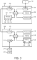
- Fig. 3 is a block diagram of the system for performing multi-modal deformable image registration according to an embodiment of the present invention.
- the processing system 100 ( Fig. 1 ) comprises a processor 110, a memory 130 operably connected to the processor such as by a system bus 120 for example, and input/output (I/O) connectors 115 that operably connect the imaging device 170 to the processor 110.
- the processor 110 may be may be any device capable of executing program instructions, such as one or more microprocessors.
- the processor 110 may be embodied in a general purpose computer.
- the memory 130 may be any volatile or non-volatile memory device suitable for storing data and program instructions, such as a removable disc, a hard drive, a CD, a Random Access Memory (RAM), a Read Only Memory (ROM), or the like. Moreover, the memory 130 may comprise one or more memory devices.
- the I/O connectors 115 may be any hardware that operably connects the processor 110 to the imaging device 170, another computer, or a data source.
- the I/O connectors may include, but are not limited to RS232 serial interface, Ethernet, and USB ports.
- the processing system 100 further comprises an imaging program 132 stored on the memory 130 and executed by the processor 110 to receive and process imaging data from the imaging device 170, and to display the images on a display 140.
- the imaging program 132 may be any be any known imaging program appropriate for the type of imaging device being used to obtain high definition images, and may include modules or units for various image processing functions.
- the processing system 100 also comprises a modeling program 134 that generates a deformation model for use in multi-modal image registration, as will be described in detail, herein.
- Fig. 4 is a flow diagram of a method for training a deformation model for use in a multi-modal deformable imaging registration according to an embodiment of the present invention.
- an embodiment is described for registering MRI images of a prostate to real-time ultrasound images of the prostate of the same subject for an image guided procedure such as a prostate biopsy or brachytherapy.
- additional embodiments may be directed to other imaging modalities than MRI, ultrasound, or both.
- additional embodiments may be directed to different body structures and different procedures.
- the imaging program 132 obtains high definition images with different deformation states for each of a plurality of subjects (Step 410).
- the images are taken at a second deformation state, with an endorectal coil (ERC) 180 inserted in the rectum which causes a deformation of the prostate, and at a first deformation state, without the ERC.
- ERC endorectal coil
- the ERC is used to enhance the image quality for prostate MRI images.
- the number of subjects is selected such that it is greater than the number of mode vectors that will be used in the deformation model. For example, a subject size of 50 may be used.
- the segmented images allow voxel by voxel identification and registration.
- the images from all of the subjects at the first deformation state are spatially aligned to a template, such as the average of the w/o ERC images from all of the subjects (Step 430).
- the spatial alignment could be realized using rigid transformation, affine transformation or a nonlinear registration or a combination of the three.
- the first deformation state (w/o ERC) MRI image is spatially aligned to the second deformation state (w/ ERC) MRI image from the same subject for each subject using an intensity-based metric (Step 440).
- the first deformation state (w/o ERC) MRI image is spatially aligned to the second deformation state (w/ ERC) MRI image from the same subject
- the first deformation state (w/o ERC) MRI image is nonlinearly warped to the second deformation state (w/ ERC) MRI image from the same subject (Step 450).
- the nonlinear warping is repeated for each subject.
- the nonlinear warping may be performed using a B-Spline registration technique with an intensity based metric.
- another nonlinear estimation technique such as a finite element method may be used to warp the second state image data to the first stage image data of the same subject to obtain a deformation field for the prostate of each subject.
- PCA principal component analysis
- the PCA is used to derive the deformation modes from the displacement fields of the sample images, as follows. If the calculated displacement fields (with three x, y, z components) are D i(mx3) . Each deformation field is reformatted to a one dimensional vector by concatenating x, y, z components from all data points for the data set.
- the first or training phase comprises calculating a deformation field using a large set of landmarks in place of intensity based registration.
- a large set of landmarks may be used.
- the landmarks are measured from the same imaging modality at different deformation states.
- a registration is performed between the landmark locations for one deformation state and the landmark locations for the other deformation states to generate a deformation field.
- the mean deformation and deformation mode Eigen vectors can be calculated from the deformation field, using principal component analysis, for example.
- the set of landmarks for the training phase is much larger than the set of landmarks used in the second phase to calculate weights for the deformation mode Eigen vectors.
- Fig. 2 shows a system for providing a second phase of a multi-modal deformable imaging registration according to an embodiment of the present invention.
- the system comprises a second imaging device 250 of a different imaging modality from the high definition imaging device 170.
- the second imaging device is an ultrasound imaging probe, more particularly a trans rectal ultrasound transducer (TRUS) for taking real-time images for an image-guided intervention procedure, such as a prostate biopsy.
- TRUS trans rectal ultrasound transducer
- any real-time imaging device or other imaging device may be used to practice the present invention.
- the TRUS 250 is operably connected with an imaging system 200.
- the imaging system 200 comprises a processor 210 for processing ultrasound images from imaging data received from the TRUS 250 and presenting them on a display 240.
- the processor 210 is operably connected with a memory 230 ( Fig. 3 ), such as through a bus 220, for example.
- I/O Input/output
- the processor 210 may be any device capable of executing program instructions, such as one or more microprocessors. Moreover, the processor 210 may be embodied in a general purpose computer.
- the memory 230 may be any volatile or non-volatile memory device suitable for storing data and program instructions, such as a removable disc, a hard drive, a CD, a Random Access Memory (RAM), a Read Only Memory (ROM), or the like. Moreover, the memory 230 may comprise one or more memory devices.
- the I/O connectors 215 may be any hardware that operably connects the processor 210 to the imaging device 250, another computer, or a data source.
- the I/O connectors may include, but are not limited to RS232 serial interface, Ethernet, and USB ports.
- the imaging system 200 and the high definition imaging system 100 are shown as two separate systems, they may, in fact, be the same system embodied in a single general purpose computer. Alternatively, the imaging data from the high definition imaging system 100 may be provided to the imaging system 200 on a storage device or be transmitted to between systems over a network, such as an intranet or the internet.
- the memory 230 has encoded thereon, an imaging program of instruction 232 executable by the processor 210 to receive imaging data from the imaging device 250 and generate images of a body structure.
- the imaging device 250 is a TRUS and the images that are generated are real-time ultrasound images of a prostate.
- the memory 230 also has encoded on it, an estimating program of instruction 234, executable by the processor 210 to estimate a deformation in a multi-modal deformable imaging registration.
- Fig. 5 is a flow diagram of a method for estimating a deformation in a multi-modal deformable imaging registration according to an embodiment of the present invention. This is the second phase of the method for providing a multi-modal deformable imaging registration.
- the estimating program of instruction 234 executed by the processor 210 spatially aligns images from two different modalities and two different deformation states for the same subject to a common reference (Step 510).
- the first image modality may be one of the high definition image modalities such as MRI from the plurality of subjects acquired in step 410 and sent by the processor 110 of the high definition imaging system 100.
- the high definition image may be acquired by the high definition imaging system 100 separately from the images used for training a template.
- the different imaging modality may be a real time ultrasound imaging modality using a TRUS probe 250 according to one embodiment of the present invention.
- an imaging system for any other modality may be used that would be advantageous to register to the high resolution image.
- the two different imaging modalities are spatially aligned to the average of the high definition images used to train the deformation model.
- any common reference may be used, so long as both images are aligned to the same reference.
- the estimating program of instruction 234 extracts landmarks from both images from the same subject (Step 520).
- the image from a different modality is an ultrasound image using a TRUS probe 250 taken in real-time.
- the real time TRUS image is used for tool guidance during an intervention for a procedure, such as a prostate biopsy.
- the other image in this embodiment is a pre-operative MRI image.
- the processor 210 executing the estimating program of instruction 234 may be the processor for the ultrasound imaging system 200 or it may be a separate processor within either imaging system or external to both imaging systems.
- the landmarks may be any landmarks visible in both images, such as the contour of the urethra or prostate surface contour points, for example.
- the points for the landmarks in each image may be extracted using any known point extraction method, such as intensity-based metrics, for example.
- the number of points extracted is preferably sufficient to solve for the Eigen values (or Eigen weights or Eigen coefficients) for all of the deformation modes calculated in step 460.
- the estimating program of instruction 234 registers the extracted landmark between the two different imaging modalities to determine a transformation matrix for the landmark points (Step 530). This transformation matrix will only be accurate for the landmarks, and will not compensate for the various deformation modes internal to the body structure.
- a deformation field estimator in the estimating program of instruction 234 estimates the deformation field for all points in the imaged body structure by summing the mean deformation and the weighted deformation modes (Step 550).
- the invention can take the form of an entirely hardware embodiment or an embodiment containing both hardware and software elements.
- the invention is implemented in software, which includes but is not limited to firmware, resident software, microcode, etc.
- the invention may take the form of a computer program product accessible from a computer-usable or computer-readable medium providing program code for use by or in connection with a computer or any instruction execution system or device.
- a computer-usable or computer readable medium may be any apparatus that can contain or store the program for use by or in connection with the instruction execution system, apparatus, or device.
- the foregoing method may be realized by a program product comprising a machine-readable medium having a machine-executable program of instructions, which when executed by a machine, such as a computer, performs the steps of the method.
- This program product may be stored on any of a variety of known machine-readable medium, including but not limited to compact discs, floppy discs, USB memory devices, and the like.
- the medium can be an electronic, magnetic, optical, electromagnetic, infrared, or semiconductor system (or apparatus or device).
- Examples of a computer-readable medium include a semiconductor or solid state memory, magnetic tape, a removable computer diskette, a random access memory (RAM), a read-only memory (ROM), a rigid magnetic disk an optical disk.
- Current examples of optical disks include compact disk-read only memory (CD-ROM), compact disk-read/write (CD-R/W) and DVD.
Description
- The invention relates to the field of medical imaging and more particularly to a method, system and computer program product for automatic multi-modality deformable registration using statistical deformation modeling and sparse deformation data.
- Image registration is an important challenge in medical image processing. The main goal in medical image registration is to calculate a geometrical transformation that aligns either the same image or different images of the same object or structure. The different images can have the same modality or different modalities. Common modalities for medical image registration include, but are not limited to: Magnetic Resonance Imaging (MRI), Computerized Tomography (CT), and Ultrasound (US).
- An important subset of image registration problems deals with matching images from different image modalities sometimes referred to as multi-modality image fusion. Multi-modal image registration is particularly challenging as the relationship between grey values of multi-modal images is not always easy to determine, and in some cases (e.g. MRI to US), a functional dependency is generally missing or very difficult to identify.
- One example of multi-modal image registration is the fusion of MRI images with US images in image-guided procedures, such as prostate biopsies or brachytherapy. The MRI modality provides high resolution anatomical images; however, MRI is expensive for intra-operative procedures such as prostate biopsies. On the other hand, the US modality is ideal for real-time imaging required for image guided procedures, such as prostate biopsy, but has quite poor image resolution. Fusion of these two modalities combines the advantage of real-time imaging (US) with high resolution imaging (MRI). For example, during a targeted prostate biopsy procedure, fusion of pre-operative MRI images with real-time US imaging is crucial in locating cancerous areas in ultrasound images that can be easily identified in MRI images. It would be advantageous to develop automatic image registration techniques to fuse pre-operative MRI images of the prostate with real-time trans-rectal ultrasound (TRUS) imaging.
- The lack of a functional dependency between the MRI and US image modalities has made it very difficult to take advantage of intensity-based metrics for image registration. Therefore, most proposed methods of MRI-to-US image fusion are focused on point matching techniques in one of two ways: (1) a set of common landmarks (such as the contour of the urethra) that are visible in the images from both modalities are either manually or automatically extracted and used for point-based registration; or (2) the surface of the prostate is segmented within each of the two modalities using automatic or manual techniques, and the extracted cloud of points are fed to a point-based registration framework that tries to minimize the distance between the two point sets.
- In the Philips Uronav system, for example, a point-based rigid registration approach is implemented to register MRI with TRUS using segmented prostate surface point data. The prostate gland is automatically segmented as a set of surface contour points in both US and MRI images. The rigid registration tries to find the best set of translation and rotation parameters that minimize the distance between the two point sets. However, the prostate is not a rigid shape, and the shape of the prostate may deform differently during acquisition of images by each of these modalities. MRI images are typically acquired while an Endorectal coil (ERC) is inserted in the rectum for enhanced image quality. The TRUS imaging is performed freehand with a TRUS probe placed in direct contact with the rectum wall adjacent to the prostate gland, thereby deforming the shape of the prostate gland during image acquisition.
- Chowdhury, Najeeb et al.: "Linked statistical shape models for multi-modal segmentation: application to prostate CT-ME segmentation in radiotherapy planning", Medical Imaging 2011 : computer-aided Diagnosis, SPIE, 1000 20th St. Bellingham WA 98225-6705 USA, vol. 7963, no.1, 3 March 2011 (2011-03-03), pages 1-15 XP060008531, DOI: 10.1117/12.878416 (hereafter "Chowdhury") provides a method for registering images from different modalities to each other using thin-plate spline (TPS) for multi-modal registration.
- A method, system and computer program product are provided for a multi-modal deformable image registration.
- According to one aspect of the invention, a method is provided for a multi-modal deformable image registration. The method comprises two phases. In the first phase a deformation model is trained to determine a mean deformation and a plurality of deformation mode vectors using images from the same "high definition" imaging modality with different deformation states. In this context, high definition refers to an imaging modality that clearly depicts structures of interest. In the second phase the deformation required to match an image from one imaging modality with one deformation state to an image from a different imaging modality with a different deformation state is estimated. To estimate the deformation between two states of deformation in two different modalities, a set of landmarks, uniquely identifiable in both modalities are extracted and nonlinearly registered. A deformation field that matches the two modalities at every point is then realized by inserting the calculated deformation values at the identified landmarks into the deformation model and solving for the Eigen coefficients of the deformation modes. Finally, the mean deformation field and the linear combination of the weighted deformation mode vectors are summed to determine the deformation field between the two imaging modes at the rest of the points.
- According to one embodiment the mean deformation and the plurality of deformation mode vectors are calculated by: for each subject, spatially aligning the images to a common reference frame; warping the imaging data for each subject from the same imaging modality and different deformation states using a similarity metric such as intensity-based metric and a non-linear transformation technique such as BSpline; and performing principal component analysis to determine the mean deformation and the plurality of deformation mode vectors.
- According to one embodiment, instead of applying deformable registration between intensity images of the same modality (with different deformation states) in the training phase, a large set of landmarks may be used. In this embodiment, instead of intensity-based registration, a point-based nonlinear registration is performed between all the landmarks at two different deformation states to generate a deformation field for the body structure of interest. Then, a mean deformation and deformation mode Eigen vectors are calculated from the deformation fields of multiple subjects.
- According to one embodiment the image from the different imaging modality is at a different deformation state from all of the deformation states used to calculate the mean deformation and the plurality of deformation mode vectors. For example, the deformation state of a prostate associated with a TRUS probe, which is different from the deformation state associated with an endorectal coil used during MRI imaging and the zero deformation state without an endorectal coil during MRI imaging.
- According to one embodiment the different imaging modality is a real-time imaging modality. In one embodiment, this real-time imaging modality is ultrasound imaging using a TRUS probe.
- According to another aspect of the present invention, a system is provided for performing a multi-modal deformable imaging registration. The system comprises: at least one processor; at least one memory operably connected to the processor; and at least one program of instruction stored on the at least one memory and executed by the at least one processor. The program of instruction comprises: program instructions for calculating a mean deformation and a plurality of deformation mode Eigen vectors for a body structure from images from the same high definition imaging mode with different deformation states for a plurality of subjects; program instructions for performing a nonlinear registration between a set of landmark points from the high definition imaging modality and a different imaging modality for the same subject to calculate the deformation field for the landmarks from the images; program instructions for determining weights for each deformation mode Eigen vector using deformation field values at the landmarks with the mean deformation and the deformation mode vectors; and program instructions for summing the mean deformation field and the linear combination of the weighted deformation mode vectors to determine the deformation field between the different imaging modes.
- According to one embodiment, the system further comprises a real-time imaging system using the different imaging modality.
- According to one embodiment, the real-time imaging system is an ultrasound imaging system and further comprises a trans-rectal ultrasound transducer operably connected to the at least one processor for generating imaging data.
- According to one embodiment, the system further comprises a high definition imaging system operably connected with the at least one processor for generating the high definition images.
- According to one embodiment, the high definition imaging system is a magnetic resonance imaging system operably connected to a magnetic resonance imaging device.
- According to one embodiment, the system further comprises an endorectal coil disposed in a subject to enhance the imaging of the high definition imaging system.
- According to one embodiment, the mean deformation and the plurality of deformation mode vectors are calculated by: for each subject, spatially aligning the images to a common reference frame; warping the imaging data for each subject from the same imaging modality but different deformation states using a similarity metric such as intensity-based metric and a non-linear transformation technique such as BSpline; and performing principal component analysis to determine the mean deformation and the plurality of deformation mode vectors.
- According to another aspect of the invention, a computer program product is provided for performing a multi-modal deformable imaging registration comprising at least one computer readable storage device having encoded thereon at least one computer executable program of instruction, the at least one computer executable program of instruction comprising: program instructions for calculating a mean deformation and a plurality of deformation mode Eigen vectors for a body structure from images from the same high definition imaging mode with different deformation states for a plurality of subjects; program instructions for performing a registration of landmark points between images from the high definition imaging modality and a different imaging modality for the same subject to calculate the deformation field for the landmarks from the images; program instructions for determining weights for each deformation mode Eigenvector using deformation field values at the landmarks with the mean deformation and the deformation mode vectors; and program instructions for summing the mean deformation field and the linear combination of the weighted deformation mode vectors to determine the deformation field between the different imaging modes.
- The features and advantages of the invention will be more clearly understood from the following detailed description of the preferred embodiments when read in connection with the accompanying drawing. Included in the drawing are the following figures:
-
Fig. 1 is an isometric view of a system for providing a first image acquisition for multi-modal deformable image registration according to an embodiment of the present invention; -
Fig. 2 is an isometric view of a system for providing a second image acquisition for multi-modal deformable image registration according to an embodiment of the present invention; -
Fig. 3 is a block diagram of a system for providing a multi-modal deformable image registration according to an embodiment of the present invention; -
Fig, 4 is a flow diagram of a method for training a deformation model for use in a multi-modal deformable imaging registration according to an embodiment of the present invention; and -
Fig. 5 is a flow diagram of a method for estimating a deformation in a multi-modal deformable imaging registration according to an embodiment of the present invention. - The present invention provides a method, system, and computer program product for a multi-modal deformable imaging registration. The multi-modal deformable registration is performed in two phases. In the first phase, a deformation model is generated for the body structure that is to be the site of the registered images. The model is generated using images from the same high definition imaging mode with different deformation states for each of a plurality of subjects. The deformation model is generated in the form of a mean deformation and a plurality of deformation mode vectors.
- In the second phase, a deformation field is estimated for deforming an image from the high definition imaging mode at one deformation states from the first phase to an image from another imaging modality with a different deformation state. A deformation field required to match images of a single subject from different modalities is estimated by performing a registration between the images from different modalities using a set of uniquely identifiable landmarks in both imaging modalities. The calculated deformation values for the limited number of landmarks are used to determine the weights for each of the deformation mode vectors. In order to determine the deformation field between the two different imaging modalities at the rest of the points (besides the landmarks used for the aforementioned registration) the mean deformation field and the linear combination of the weighted deformation mode vectors are summed.
-
Fig. 1 shows a system for providing a first phase of a multi-modal deformable imaging registration according to an embodiment of the present invention. The system comprises a highdefinition imaging device 170. In the illustrated example, the high definition imaging device is an MRI device for taking MRI images. However, it should be understood that any other high definition imaging device, such as a CT or ultrasound machines, may also be used to practice the present invention. - The system for performing the first phase of a multi-modal deformable image registration also comprises a
processing system 100, such as a general purpose computer or other processing device. -
Fig. 3 is a block diagram of the system for performing multi-modal deformable image registration according to an embodiment of the present invention. As shown inFig. 3 , the processing system 100 (Fig. 1 ) comprises a processor 110, amemory 130 operably connected to the processor such as by asystem bus 120 for example, and input/output (I/O)connectors 115 that operably connect theimaging device 170 to the processor 110. The processor 110 may be may be any device capable of executing program instructions, such as one or more microprocessors. Moreover, the processor 110 may be embodied in a general purpose computer. - The
memory 130 may be any volatile or non-volatile memory device suitable for storing data and program instructions, such as a removable disc, a hard drive, a CD, a Random Access Memory (RAM), a Read Only Memory (ROM), or the like. Moreover, thememory 130 may comprise one or more memory devices. - The I/
O connectors 115 may be any hardware that operably connects the processor 110 to theimaging device 170, another computer, or a data source. The I/O connectors may include, but are not limited to RS232 serial interface, Ethernet, and USB ports. - The
processing system 100 further comprises animaging program 132 stored on thememory 130 and executed by the processor 110 to receive and process imaging data from theimaging device 170, and to display the images on adisplay 140. Theimaging program 132 may be any be any known imaging program appropriate for the type of imaging device being used to obtain high definition images, and may include modules or units for various image processing functions. - The
processing system 100 also comprises amodeling program 134 that generates a deformation model for use in multi-modal image registration, as will be described in detail, herein. -
Fig. 4 is a flow diagram of a method for training a deformation model for use in a multi-modal deformable imaging registration according to an embodiment of the present invention. In the following description, an embodiment is described for registering MRI images of a prostate to real-time ultrasound images of the prostate of the same subject for an image guided procedure such as a prostate biopsy or brachytherapy. However, as will be understood by those skilled in the art, additional embodiments may be directed to other imaging modalities than MRI, ultrasound, or both. Also, additional embodiments may be directed to different body structures and different procedures. - The
imaging program 132 obtains high definition images with different deformation states for each of a plurality of subjects (Step 410). In the illustrated example, the images are taken at a second deformation state, with an endorectal coil (ERC) 180 inserted in the rectum which causes a deformation of the prostate, and at a first deformation state, without the ERC. As is known in the art, the ERC is used to enhance the image quality for prostate MRI images. The number of subjects is selected such that it is greater than the number of mode vectors that will be used in the deformation model. For example, a subject size of 50 may be used. - Optionally, the segmented images allow voxel by voxel identification and registration.
- The images from all of the subjects at the first deformation state (w/o ERC MRI) are spatially aligned to a template, such as the average of the w/o ERC images from all of the subjects (Step 430). The spatial alignment could be realized using rigid transformation, affine transformation or a nonlinear registration or a combination of the three.
- Then the first deformation state (w/o ERC) MRI image is spatially aligned to the second deformation state (w/ ERC) MRI image from the same subject for each subject using an intensity-based metric (Step 440).
- After the first deformation state (w/o ERC) MRI image is spatially aligned to the second deformation state (w/ ERC) MRI image from the same subject, the first deformation state (w/o ERC) MRI image is nonlinearly warped to the second deformation state (w/ ERC) MRI image from the same subject (Step 450). The nonlinear warping is repeated for each subject.
- The nonlinear warping may be performed using a B-Spline registration technique with an intensity based metric. Alternatively, another nonlinear estimation technique such as a finite element method may be used to warp the second state image data to the first stage image data of the same subject to obtain a deformation field for the prostate of each subject. The formula for the deformation field is the following:

d stand for deformation field resulting from the nonlinear registration of w/oERC to wERC MRI for sample training data i and mean deformation field, respectively. - Then, the mean deformation is calculated and principal component analysis (PCA) is used to derive deformation modes from the displacement fields of the subjects used in the first (model) phase of the multi-modal image registration (Step 460).
- The mean deformation is calculated by averaging the deformations of the plurality of subjects:

- The PCA is used to derive the deformation modes from the displacement fields of the sample images, as follows. If the calculated displacement fields (with three x, y, z components) are Di(mx3). Each deformation field is reformatted to a one dimensional vector by concatenating x, y, z components from all data points for the data set.
- The covariance matrix ∑ is calculated as follows:

- The matrix of deformation eigenvectors, Ψ, which diagonalize the covariance matrix ∑ is found as:

- The Eigen vectors of the displacement field matrix (Dmxn), where m is the number of data points in a data set is found by:

- Any displacement field can be estimated from the linear combination of the mean deformation plus the linear combination of the deformation modes (ϕi) as follows:.

- In an alternate embodiment the first or training phase comprises calculating a deformation field using a large set of landmarks in place of intensity based registration. Instead of applying deformable registration between intensity images from the same imaging modality (with different deformation states), a large set of landmarks may be used. The landmarks are measured from the same imaging modality at different deformation states. A registration is performed between the landmark locations for one deformation state and the landmark locations for the other deformation states to generate a deformation field. The mean deformation and deformation mode Eigen vectors can be calculated from the deformation field, using principal component analysis, for example. In this embodiment, the set of landmarks for the training phase is much larger than the set of landmarks used in the second phase to calculate weights for the deformation mode Eigen vectors.
-
Fig. 2 shows a system for providing a second phase of a multi-modal deformable imaging registration according to an embodiment of the present invention. The system comprises asecond imaging device 250 of a different imaging modality from the highdefinition imaging device 170. In the illustrated example, the second imaging device is an ultrasound imaging probe, more particularly a trans rectal ultrasound transducer (TRUS) for taking real-time images for an image-guided intervention procedure, such as a prostate biopsy. However, it should be understood that any real-time imaging device or other imaging device may be used to practice the present invention. - The
TRUS 250 is operably connected with animaging system 200. As shown inFig. 3 , theimaging system 200 comprises aprocessor 210 for processing ultrasound images from imaging data received from theTRUS 250 and presenting them on adisplay 240. Theprocessor 210 is operably connected with a memory 230 (Fig. 3 ), such as through abus 220, for example. Input/output (I/O)connectors 215 that operably connect theimaging device 250 to theprocessor 210 and the highdefinition imaging system 100 to theprocessor 210. - The
processor 210 may be any device capable of executing program instructions, such as one or more microprocessors. Moreover, theprocessor 210 may be embodied in a general purpose computer. - The
memory 230 may be any volatile or non-volatile memory device suitable for storing data and program instructions, such as a removable disc, a hard drive, a CD, a Random Access Memory (RAM), a Read Only Memory (ROM), or the like. Moreover, thememory 230 may comprise one or more memory devices. - The I/
O connectors 215 may be any hardware that operably connects theprocessor 210 to theimaging device 250, another computer, or a data source.. The I/O connectors may include, but are not limited to RS232 serial interface, Ethernet, and USB ports. - While the
imaging system 200 and the highdefinition imaging system 100 are shown as two separate systems, they may, in fact, be the same system embodied in a single general purpose computer. Alternatively, the imaging data from the highdefinition imaging system 100 may be provided to theimaging system 200 on a storage device or be transmitted to between systems over a network, such as an intranet or the internet. - The
memory 230 has encoded thereon, an imaging program of instruction 232 executable by theprocessor 210 to receive imaging data from theimaging device 250 and generate images of a body structure. In the illustrated embodiment, theimaging device 250 is a TRUS and the images that are generated are real-time ultrasound images of a prostate. - The
memory 230 also has encoded on it, an estimating program of instruction 234, executable by theprocessor 210 to estimate a deformation in a multi-modal deformable imaging registration. -
Fig. 5 is a flow diagram of a method for estimating a deformation in a multi-modal deformable imaging registration according to an embodiment of the present invention. This is the second phase of the method for providing a multi-modal deformable imaging registration. - The estimating program of instruction 234 executed by the
processor 210 spatially aligns images from two different modalities and two different deformation states for the same subject to a common reference (Step 510). The first image modality may be one of the high definition image modalities such as MRI from the plurality of subjects acquired instep 410 and sent by the processor 110 of the highdefinition imaging system 100. Alternatively, the high definition image may be acquired by the highdefinition imaging system 100 separately from the images used for training a template. - The different imaging modality may be a real time ultrasound imaging modality using a
TRUS probe 250 according to one embodiment of the present invention. Alternatively, an imaging system for any other modality may be used that would be advantageous to register to the high resolution image. - According to one embodiment, the two different imaging modalities are spatially aligned to the average of the high definition images used to train the deformation model. However, any common reference may be used, so long as both images are aligned to the same reference.
- The estimating program of instruction 234 extracts landmarks from both images from the same subject (Step 520). In the illustrated embodiment, the image from a different modality is an ultrasound image using a
TRUS probe 250 taken in real-time. The real time TRUS image is used for tool guidance during an intervention for a procedure, such as a prostate biopsy. The other image in this embodiment is a pre-operative MRI image. Theprocessor 210 executing the estimating program of instruction 234 may be the processor for theultrasound imaging system 200 or it may be a separate processor within either imaging system or external to both imaging systems. - The landmarks may be any landmarks visible in both images, such as the contour of the urethra or prostate surface contour points, for example. The points for the landmarks in each image may be extracted using any known point extraction method, such as intensity-based metrics, for example. The number of points extracted is preferably sufficient to solve for the Eigen values (or Eigen weights or Eigen coefficients) for all of the deformation modes calculated in step 460.
- The estimating program of instruction 234 registers the extracted landmark between the two different imaging modalities to determine a transformation matrix for the landmark points (Step 530). This transformation matrix will only be accurate for the landmarks, and will not compensate for the various deformation modes internal to the body structure.
- Using the calculated deformation field for matching landmark points with the mean deformation and the Eigen vectors from the deformation model calculated in Step 460, a deformation model solver in the estimating program of instructions 234 calculates Eigen coefficients αi or Eigen values for each deformation mode i where i = 1, 2, ..., k (Step 540). The deformation model solver calculates the Eigen weights as follows.

- Then, a deformation field estimator in the estimating program of instruction 234 estimates the deformation field for all points in the imaged body structure by summing the mean deformation and the weighted deformation modes (Step 550). The deformation field estimator sums the mean deformation from step 460 and the linear combination of deformation modes from step 460 with the Eigen values from
step 540 as follows.
- The invention can take the form of an entirely hardware embodiment or an embodiment containing both hardware and software elements. In an exemplary embodiment, the invention is implemented in software, which includes but is not limited to firmware, resident software, microcode, etc.
- Furthermore, the invention may take the form of a computer program product accessible from a computer-usable or computer-readable medium providing program code for use by or in connection with a computer or any instruction execution system or device. For the purposes of this description, a computer-usable or computer readable medium may be any apparatus that can contain or store the program for use by or in connection with the instruction execution system, apparatus, or device.
- The foregoing method may be realized by a program product comprising a machine-readable medium having a machine-executable program of instructions, which when executed by a machine, such as a computer, performs the steps of the method. This program product may be stored on any of a variety of known machine-readable medium, including but not limited to compact discs, floppy discs, USB memory devices, and the like.
- The medium can be an electronic, magnetic, optical, electromagnetic, infrared, or semiconductor system (or apparatus or device). Examples of a computer-readable medium include a semiconductor or solid state memory, magnetic tape, a removable computer diskette, a random access memory (RAM), a read-only memory (ROM), a rigid magnetic disk an optical disk. Current examples of optical disks include compact disk-read only memory (CD-ROM), compact disk-read/write (CD-R/W) and DVD.
- The preceding description and accompanying drawing are intended to be illustrative and not limiting of the invention. The scope of the invention is intended to encompass the full extent of the following claims.
Claims (15)
- A method for providing a multi-modal deformable imaging registration, comprising the steps of:generating (430 - 450)a deformation model of a structure of interest acquired with a high definition imaging modality at different deformation states for a plurality of subjects;calculating (460) a mean deformation and a plurality of deformation mode Eigenvectors for the body structure of interest from the model;performing (530) a registration of landmark points between images from the high definition imaging modality and a different imaging modality for the same subject to calculate the deformation field transformation matrix for the landmarks from the images; and determining weights for each deformation mode Eigenvector,characterized in that the step of determining (540) weights for each deformation mode Eigenvector includes using deformation field values at the landmarks with the mean deformation and the deformation mode Eigenvectors; and that the method further comprises the step ofsumming (550) the mean deformation field and the linear combination of the weighted deformation mode Eigenvectors to determine the deformation field between the different imaging modes.
- The method of claim 1, wherein the mean deformation and the plurality of deformation mode vectors are calculated by:for each subject, spatially aligning the images to a common reference frame;warping the imaging data for each subject from the different deformation states using an image similarity metric and a non-linear transformation technique; andperforming principal component analysis to determine the mean deformation and the plurality of deformation mode vectors.
- The method of claim 1, wherein the mean deformation and the plurality of deformation mode vectors are calculated by:for each subject, measuring locations for a set of landmarks;performing point-based nonlinear registration between all the landmarks; and generate a deformation model for the landmarks.
- The method of claim 1, wherein the image from the different modality is at a different deformation state from all of the deformation states used to calculate the mean deformation and the plurality of deformation mode vectors.
- The method of claim 1, wherein the different imaging modality is a real-time imaging modality.
- The method of claim 5, wherein the different imaging modality is transrectal ultrasound imaging (TRUS).
- The method of claim 6, wherein the body structure is a prostate.
- A system for providing a multi-modal deformable imaging registration, comprising:at least one processor (110, 210);at least one memory (130, 230) operably connected to the processor; andat least one program of instruction (234) stored on the at least one memory, the at least one processor being configured to execute the at least one program of instruction; wherein the program of instruction comprises:program instructions for generating a deformation model of a structure of interest acquired with a high definition imaging modality at different deformation states for a plurality of subjects;program instructions for calculating a mean deformation and a plurality of deformation mode Eigenvectors for the body structure of interest from the model; andprogram instructions for performing a registration of landmark points between images from the high definition imaging modality and a different imaging modality for the same subject to calculate the deformation field transformation matrix for the landmarks from the imagescharacterized in that the program of instruction further comprises:program instructions for determining weights for each deformation modeEigenvector using deformation field values at the landmarks with the mean deformation and the deformation mode Eigenvectors; andprogram instructions for summing the mean deformation field and the linear combination of the weighted deformation mode Eigenvectors to determine the deformation field between the different imaging modes for all points in the image.
- The system of claim 8, further comprising a real-time imaging system (200) using the different imaging modality.
- The system of claim 9, wherein the real-time imaging system is an ultrasound imaging system and further comprises a trans rectal ultrasound probe (250) operably connected to the at least one processor for generating imaging data.
- The system of claim 8, further comprising a high definition imaging system (170) operably connected with the at least one processor (100) for generating the high definition images.
- The system of claim 11, wherein the high definition imaging system is a magnetic resonance imaging system operably connected to a magnetic resonance imaging device.
- The system of claim 12, further comprising an endorectal coil disposed in a subject to enhance the imaging of the high definition imaging system.
- The system of claim 8, wherein the mean deformation and the plurality of deformation mode vectors are calculated by:for each subject, spatially aligning the images to a common reference frame;warping the imaging data for each subject from the different deformation states using an image similarity metric and a non-linear transformation technique; andperforming principal component analysis to determine the mean deformation and the plurality of deformation mode vectors.
- A computer program product for providing a multi-modal deformable imaging registration, comprising at least one computer readable storage device having encoded thereon at least one computer executable program of instruction, the at least one computer executable program of instruction comprising:program instructions for generating a deformation model of a structure of interest acquired with a high definition imaging modality at different deformation states for a plurality of subjects;program instructions for calculating a mean deformation and a plurality of deformation mode Eigenvectors for the body structure of interest from the model; andprogram instructions for performing a registration of landmark points between images from the high definition imaging modality and a different imaging modality for the same subject to calculate the deformation field transformation matrix for the landmarks from the imagescharacterized in that the computer executable program of instruction further comprises:program instructions for determining weights for each deformation mode Eigenvector using deformation field values at the landmarks with the mean deformation and the deformation mode Eigenvectors; andprogram instructions for summing the mean deformation field and the linear combination of the weighted deformation mode Eigenvectors to determine the deformation field between the different imaging modes.
Applications Claiming Priority (3)
| Application Number | Priority Date | Filing Date | Title |
|---|---|---|---|
| US201261611071P | 2012-03-15 | 2012-03-15 | |
| US201261679218P | 2012-08-03 | 2012-08-03 | |
| PCT/IB2013/051991 WO2013136278A1 (en) | 2012-03-15 | 2013-03-13 | Multi-modality deformable registration |
Publications (2)
| Publication Number | Publication Date |
|---|---|
| EP2826019A1 EP2826019A1 (en) | 2015-01-21 |
| EP2826019B1 true EP2826019B1 (en) | 2016-05-18 |
Family
ID=48468679
Family Applications (1)
| Application Number | Title | Priority Date | Filing Date |
|---|---|---|---|
| EP13723954.7A Active EP2826019B1 (en) | 2012-03-15 | 2013-03-13 | Multi-modality deformable registration |
Country Status (6)
| Country | Link |
|---|---|
| US (1) | US9240032B2 (en) |
| EP (1) | EP2826019B1 (en) |
| JP (1) | JP6207534B2 (en) |
| CN (1) | CN104169969B (en) |
| RU (1) | RU2014141502A (en) |
| WO (1) | WO2013136278A1 (en) |
Families Citing this family (21)
| Publication number | Priority date | Publication date | Assignee | Title |
|---|---|---|---|---|
| US9401051B2 (en) * | 2010-06-23 | 2016-07-26 | Varian Medical Systems International Ag | Mechanism for dynamically propagating real-time alterations of medical images |
| KR102114415B1 (en) * | 2013-01-29 | 2020-05-22 | 삼성전자주식회사 | Method and Apparatus for medical image registration |
| US20160143576A1 (en) * | 2013-07-15 | 2016-05-26 | Tel Hashomer Medical Research Infrastructure And Services Ltd. | Mri image fusion methods and uses thereof |
| CN105593902A (en) * | 2013-09-30 | 2016-05-18 | 皇家飞利浦有限公司 | Method and system for automatic deformable registration |
| CN104515961B (en) * | 2013-09-30 | 2018-02-13 | 西门子(深圳)磁共振有限公司 | MR imaging method and device |
| DE112015002791T5 (en) | 2014-06-13 | 2017-03-16 | Siemens Medical Solutions Usa, Inc. | Intra-reconstruction movement correction |
| JP6670257B2 (en) | 2014-06-18 | 2020-03-18 | コーニンクレッカ フィリップス エヌ ヴェKoninklijke Philips N.V. | Ultrasound imaging device |
| GB2529139B (en) * | 2014-07-08 | 2017-08-02 | Siemens Medical Solutions Usa Inc | Methods and systems for feature-based registration of patient medical images |
| US10269115B2 (en) * | 2014-07-15 | 2019-04-23 | Koninklijke Philips N.V. | Imaging data statistical testing including a stereotactical normalization with a personalized template image |
| GB201416416D0 (en) * | 2014-09-17 | 2014-10-29 | Biomediq As | Bias correction in images |
| DE102014219915B3 (en) * | 2014-10-01 | 2015-11-12 | Siemens Aktiengesellschaft | A method of compensating for spatial mapping errors of PET data and imaging system caused by a patient's cyclic motion |
| US10169681B2 (en) * | 2014-12-15 | 2019-01-01 | Koninklijke Philips N.V. | Quality control of image registration |
| JP6682243B2 (en) * | 2015-01-09 | 2020-04-15 | キヤノンメディカルシステムズ株式会社 | Medical image diagnostic apparatus, image processing apparatus, and image processing method |
| US11051902B2 (en) * | 2015-09-09 | 2021-07-06 | Koninklijke Philips N.V. | System and method for planning and performing a repeat interventional procedure |
| WO2017158575A1 (en) * | 2016-03-17 | 2017-09-21 | Imagia Cybernetics Inc. | Method and system for processing a task with robustness to missing input information |
| US10402969B2 (en) * | 2017-03-10 | 2019-09-03 | General Electric Company | Methods and systems for model driven multi-modal medical imaging |
| JP7139637B2 (en) | 2018-03-19 | 2022-09-21 | 株式会社リコー | Image processing device and projection system |
| US11484279B2 (en) | 2018-09-24 | 2022-11-01 | Siemens Medical Solutions Usa, Inc. | Systems to assess projection data inconsistency |
| CN109544447B (en) * | 2018-10-26 | 2022-10-21 | 广西师范大学 | Image splicing method and device and storage medium |
| CN111047629B (en) * | 2019-11-04 | 2022-04-26 | 中国科学院深圳先进技术研究院 | Multi-modal image registration method and device, electronic equipment and storage medium |
| CN113393498B (en) * | 2021-05-26 | 2023-07-25 | 上海联影医疗科技股份有限公司 | Image registration method, device, computer equipment and storage medium |
Family Cites Families (16)
| Publication number | Priority date | Publication date | Assignee | Title |
|---|---|---|---|---|
| US7103399B2 (en) * | 2003-09-08 | 2006-09-05 | Vanderbilt University | Apparatus and methods of cortical surface registration and deformation tracking for patient-to-image alignment in relation to image-guided surgery |
| US8358819B2 (en) * | 2005-06-24 | 2013-01-22 | University Of Iowa Research Foundation | System and methods for image segmentation in N-dimensional space |
| WO2007035688A2 (en) * | 2005-09-16 | 2007-03-29 | The Ohio State University | Method and apparatus for detecting intraventricular dyssynchrony |
| GB0521640D0 (en) * | 2005-10-24 | 2005-11-30 | Ccbr As | Automatic quantification of a pathology indicating measure from cartilage scan data |
| US20070167784A1 (en) | 2005-12-13 | 2007-07-19 | Raj Shekhar | Real-time Elastic Registration to Determine Temporal Evolution of Internal Tissues for Image-Guided Interventions |
| WO2008052312A1 (en) * | 2006-10-10 | 2008-05-08 | Cedara Software Corp. | System and method for segmenting a region in a medical image |
| US8175350B2 (en) * | 2007-01-15 | 2012-05-08 | Eigen, Inc. | Method for tissue culture extraction |
| CA2683805C (en) * | 2007-04-13 | 2014-09-23 | The Regents Of The University Of Michigan | Systems and methods for tissue imaging |
| US20090326363A1 (en) | 2008-05-02 | 2009-12-31 | Eigen, Llc | Fused image modalities guidance |
| DE102008032006B4 (en) * | 2008-07-07 | 2017-01-05 | Siemens Healthcare Gmbh | Method for controlling the image recording in an image recording device, and an image recording device |
| WO2010061322A1 (en) * | 2008-11-25 | 2010-06-03 | Koninklijke Philips Electronics N.V. | Image provision for registration |
| EP2396765B1 (en) * | 2009-02-11 | 2016-03-30 | Koninklijke Philips N.V. | Group-wise image registration based on motion model |
| US9521994B2 (en) * | 2009-05-11 | 2016-12-20 | Siemens Healthcare Gmbh | System and method for image guided prostate cancer needle biopsy |
| GB0913930D0 (en) * | 2009-08-07 | 2009-09-16 | Ucl Business Plc | Apparatus and method for registering two medical images |
| JP5546230B2 (en) * | 2009-12-10 | 2014-07-09 | キヤノン株式会社 | Information processing apparatus, information processing method, and program |
| JP2014056371A (en) * | 2012-09-12 | 2014-03-27 | Fujitsu Semiconductor Ltd | Image processing apparatus |
-
2013
- 2013-03-13 WO PCT/IB2013/051991 patent/WO2013136278A1/en active Application Filing
- 2013-03-13 JP JP2014561571A patent/JP6207534B2/en active Active
- 2013-03-13 CN CN201380013910.7A patent/CN104169969B/en active Active
- 2013-03-13 EP EP13723954.7A patent/EP2826019B1/en active Active
- 2013-03-13 RU RU2014141502A patent/RU2014141502A/en not_active Application Discontinuation
- 2013-03-13 US US14/384,163 patent/US9240032B2/en active Active
Also Published As
| Publication number | Publication date |
|---|---|
| CN104169969B (en) | 2017-03-29 |
| RU2014141502A (en) | 2016-05-10 |
| CN104169969A (en) | 2014-11-26 |
| WO2013136278A1 (en) | 2013-09-19 |
| US9240032B2 (en) | 2016-01-19 |
| JP2015515297A (en) | 2015-05-28 |
| JP6207534B2 (en) | 2017-10-04 |
| EP2826019A1 (en) | 2015-01-21 |
| US20150043794A1 (en) | 2015-02-12 |
Similar Documents
| Publication | Publication Date | Title |
|---|---|---|
| EP2826019B1 (en) | Multi-modality deformable registration | |
| EP2462560B1 (en) | Apparatus and method for registering two medical images | |
| Skerl et al. | A protocol for evaluation of similarity measures for rigid registration | |
| US8526691B2 (en) | System and method for passive medical device navigation under real-time MRI guidance | |
| JP6537981B2 (en) | Segmentation of large objects from multiple 3D views | |
| US20160217560A1 (en) | Method and system for automatic deformable registration | |
| Wein et al. | Global registration of ultrasound to MRI using the LC 2 metric for enabling neurosurgical guidance | |
| Yang et al. | 3D prostate segmentation of ultrasound images combining longitudinal image registration and machine learning | |
| De Silva et al. | 2D‐3D rigid registration to compensate for prostate motion during 3D TRUS‐guided biopsy | |
| WO2010034099A1 (en) | Ac-pc segmentation system and method | |
| Tadayyon et al. | Target motion tracking in MRI-guided transrectal robotic prostate biopsy | |
| Nir et al. | Model-based registration of ex vivo and in vivo MRI of the prostate using elastography | |
| Schalk et al. | 3D surface-based registration of ultrasound and histology in prostate cancer imaging | |
| Wein et al. | Automatic non-linear mapping of pre-procedure CT volumes to 3D ultrasound | |
| De Nigris et al. | Fast and robust registration based on gradient orientations: case study matching intra-operative ultrasound to pre-operative mri in neurosurgery | |
| EP3234917B1 (en) | Method and system for calculating a displacement of an object of interest | |
| Tadayyon et al. | Target motion compensation in MRI-guided prostate biopsy with static images | |
| Onofrey et al. | Learning nonrigid deformations for constrained point-based registration for image-guided MR-TRUS prostate intervention | |
| Leung et al. | A real-time intrasubject elastic registration algorithm for dynamic 2-D ultrasound images | |
| Škerl et al. | Comparative evaluation of similarity measures for the rigid registration of multi-modal head images | |
| Arbel et al. | Fast and efficient image registration based on gradient orientations of minimal uncertainty | |
| Lakshmanan et al. | Affine based image registration applied to MRI brain | |
| King et al. | Image-to-physical registration for image-guided interventions using 3-D ultrasound and an ultrasound imaging model | |
| Zhang et al. | A multiscale adaptive mask method for rigid intraoperative ultrasound and preoperative CT image registration | |
| Moradi et al. | Mri confirmed prostate tissue classification with laplacian eigenmaps of ultrasound rf spectra |
Legal Events
| Date | Code | Title | Description |
|---|---|---|---|
| PUAI | Public reference made under article 153(3) epc to a published international application that has entered the european phase |
Free format text: ORIGINAL CODE: 0009012 |
|
| 17P | Request for examination filed |
Effective date: 20141015 |
|
| AK | Designated contracting states |
Kind code of ref document: A1 Designated state(s): AL AT BE BG CH CY CZ DE DK EE ES FI FR GB GR HR HU IE IS IT LI LT LU LV MC MK MT NL NO PL PT RO RS SE SI SK SM TR |
|
| AX | Request for extension of the european patent |
Extension state: BA ME |
|
| DAX | Request for extension of the european patent (deleted) | ||
| REG | Reference to a national code |
Ref country code: DE Ref legal event code: R079 Ref document number: 602013007694 Country of ref document: DE Free format text: PREVIOUS MAIN CLASS: G06T0007000000 Ipc: G06T0003000000 |
|
| RIC1 | Information provided on ipc code assigned before grant |
Ipc: G06T 3/00 20060101AFI20150901BHEP Ipc: G06T 7/00 20060101ALI20150901BHEP |
|
| GRAP | Despatch of communication of intention to grant a patent |
Free format text: ORIGINAL CODE: EPIDOSNIGR1 |
|
| INTG | Intention to grant announced |
Effective date: 20151116 |
|
| GRAS | Grant fee paid |
Free format text: ORIGINAL CODE: EPIDOSNIGR3 |
|
| GRAA | (expected) grant |
Free format text: ORIGINAL CODE: 0009210 |
|
| AK | Designated contracting states |
Kind code of ref document: B1 Designated state(s): AL AT BE BG CH CY CZ DE DK EE ES FI FR GB GR HR HU IE IS IT LI LT LU LV MC MK MT NL NO PL PT RO RS SE SI SK SM TR |
|
| REG | Reference to a national code |
Ref country code: GB Ref legal event code: FG4D |
|
| REG | Reference to a national code |
Ref country code: CH Ref legal event code: EP |
|
| REG | Reference to a national code |
Ref country code: IE Ref legal event code: FG4D Ref country code: AT Ref legal event code: REF Ref document number: 801052 Country of ref document: AT Kind code of ref document: T Effective date: 20160615 |
|
| REG | Reference to a national code |
Ref country code: DE Ref legal event code: R096 Ref document number: 602013007694 Country of ref document: DE |
|
| REG | Reference to a national code |
Ref country code: NL Ref legal event code: MP Effective date: 20160518 |
|
| REG | Reference to a national code |
Ref country code: LT Ref legal event code: MG4D |
|
| PG25 | Lapsed in a contracting state [announced via postgrant information from national office to epo] |
Ref country code: FI Free format text: LAPSE BECAUSE OF FAILURE TO SUBMIT A TRANSLATION OF THE DESCRIPTION OR TO PAY THE FEE WITHIN THE PRESCRIBED TIME-LIMIT Effective date: 20160518 Ref country code: LT Free format text: LAPSE BECAUSE OF FAILURE TO SUBMIT A TRANSLATION OF THE DESCRIPTION OR TO PAY THE FEE WITHIN THE PRESCRIBED TIME-LIMIT Effective date: 20160518 Ref country code: NO Free format text: LAPSE BECAUSE OF FAILURE TO SUBMIT A TRANSLATION OF THE DESCRIPTION OR TO PAY THE FEE WITHIN THE PRESCRIBED TIME-LIMIT Effective date: 20160818 Ref country code: NL Free format text: LAPSE BECAUSE OF FAILURE TO SUBMIT A TRANSLATION OF THE DESCRIPTION OR TO PAY THE FEE WITHIN THE PRESCRIBED TIME-LIMIT Effective date: 20160518 |
|
| REG | Reference to a national code |
Ref country code: AT Ref legal event code: MK05 Ref document number: 801052 Country of ref document: AT Kind code of ref document: T Effective date: 20160518 |
|
| PG25 | Lapsed in a contracting state [announced via postgrant information from national office to epo] |
Ref country code: PT Free format text: LAPSE BECAUSE OF FAILURE TO SUBMIT A TRANSLATION OF THE DESCRIPTION OR TO PAY THE FEE WITHIN THE PRESCRIBED TIME-LIMIT Effective date: 20160919 Ref country code: GR Free format text: LAPSE BECAUSE OF FAILURE TO SUBMIT A TRANSLATION OF THE DESCRIPTION OR TO PAY THE FEE WITHIN THE PRESCRIBED TIME-LIMIT Effective date: 20160819 Ref country code: SE Free format text: LAPSE BECAUSE OF FAILURE TO SUBMIT A TRANSLATION OF THE DESCRIPTION OR TO PAY THE FEE WITHIN THE PRESCRIBED TIME-LIMIT Effective date: 20160518 Ref country code: HR Free format text: LAPSE BECAUSE OF FAILURE TO SUBMIT A TRANSLATION OF THE DESCRIPTION OR TO PAY THE FEE WITHIN THE PRESCRIBED TIME-LIMIT Effective date: 20160518 Ref country code: LV Free format text: LAPSE BECAUSE OF FAILURE TO SUBMIT A TRANSLATION OF THE DESCRIPTION OR TO PAY THE FEE WITHIN THE PRESCRIBED TIME-LIMIT Effective date: 20160518 Ref country code: RS Free format text: LAPSE BECAUSE OF FAILURE TO SUBMIT A TRANSLATION OF THE DESCRIPTION OR TO PAY THE FEE WITHIN THE PRESCRIBED TIME-LIMIT Effective date: 20160518 Ref country code: ES Free format text: LAPSE BECAUSE OF FAILURE TO SUBMIT A TRANSLATION OF THE DESCRIPTION OR TO PAY THE FEE WITHIN THE PRESCRIBED TIME-LIMIT Effective date: 20160518 |
|
| PG25 | Lapsed in a contracting state [announced via postgrant information from national office to epo] |
Ref country code: IT Free format text: LAPSE BECAUSE OF FAILURE TO SUBMIT A TRANSLATION OF THE DESCRIPTION OR TO PAY THE FEE WITHIN THE PRESCRIBED TIME-LIMIT Effective date: 20160518 |
|
| PG25 | Lapsed in a contracting state [announced via postgrant information from national office to epo] |
Ref country code: DK Free format text: LAPSE BECAUSE OF FAILURE TO SUBMIT A TRANSLATION OF THE DESCRIPTION OR TO PAY THE FEE WITHIN THE PRESCRIBED TIME-LIMIT Effective date: 20160518 Ref country code: SK Free format text: LAPSE BECAUSE OF FAILURE TO SUBMIT A TRANSLATION OF THE DESCRIPTION OR TO PAY THE FEE WITHIN THE PRESCRIBED TIME-LIMIT Effective date: 20160518 Ref country code: CZ Free format text: LAPSE BECAUSE OF FAILURE TO SUBMIT A TRANSLATION OF THE DESCRIPTION OR TO PAY THE FEE WITHIN THE PRESCRIBED TIME-LIMIT Effective date: 20160518 Ref country code: EE Free format text: LAPSE BECAUSE OF FAILURE TO SUBMIT A TRANSLATION OF THE DESCRIPTION OR TO PAY THE FEE WITHIN THE PRESCRIBED TIME-LIMIT Effective date: 20160518 Ref country code: RO Free format text: LAPSE BECAUSE OF FAILURE TO SUBMIT A TRANSLATION OF THE DESCRIPTION OR TO PAY THE FEE WITHIN THE PRESCRIBED TIME-LIMIT Effective date: 20160518 |
|
| REG | Reference to a national code |
Ref country code: DE Ref legal event code: R097 Ref document number: 602013007694 Country of ref document: DE |
|
| PG25 | Lapsed in a contracting state [announced via postgrant information from national office to epo] |
Ref country code: AT Free format text: LAPSE BECAUSE OF FAILURE TO SUBMIT A TRANSLATION OF THE DESCRIPTION OR TO PAY THE FEE WITHIN THE PRESCRIBED TIME-LIMIT Effective date: 20160518 Ref country code: SM Free format text: LAPSE BECAUSE OF FAILURE TO SUBMIT A TRANSLATION OF THE DESCRIPTION OR TO PAY THE FEE WITHIN THE PRESCRIBED TIME-LIMIT Effective date: 20160518 Ref country code: BE Free format text: LAPSE BECAUSE OF FAILURE TO SUBMIT A TRANSLATION OF THE DESCRIPTION OR TO PAY THE FEE WITHIN THE PRESCRIBED TIME-LIMIT Effective date: 20160518 Ref country code: PL Free format text: LAPSE BECAUSE OF FAILURE TO SUBMIT A TRANSLATION OF THE DESCRIPTION OR TO PAY THE FEE WITHIN THE PRESCRIBED TIME-LIMIT Effective date: 20160518 |
|
| PLBE | No opposition filed within time limit |
Free format text: ORIGINAL CODE: 0009261 |
|
| STAA | Information on the status of an ep patent application or granted ep patent |
Free format text: STATUS: NO OPPOSITION FILED WITHIN TIME LIMIT |
|
| REG | Reference to a national code |
Ref country code: FR Ref legal event code: PLFP Year of fee payment: 5 |
|
| 26N | No opposition filed |
Effective date: 20170221 |
|
| PG25 | Lapsed in a contracting state [announced via postgrant information from national office to epo] |
Ref country code: SI Free format text: LAPSE BECAUSE OF FAILURE TO SUBMIT A TRANSLATION OF THE DESCRIPTION OR TO PAY THE FEE WITHIN THE PRESCRIBED TIME-LIMIT Effective date: 20160518 |
|
| REG | Reference to a national code |
Ref country code: CH Ref legal event code: PL |
|
| PG25 | Lapsed in a contracting state [announced via postgrant information from national office to epo] |
Ref country code: MC Free format text: LAPSE BECAUSE OF FAILURE TO SUBMIT A TRANSLATION OF THE DESCRIPTION OR TO PAY THE FEE WITHIN THE PRESCRIBED TIME-LIMIT Effective date: 20160518 |
|
| REG | Reference to a national code |
Ref country code: IE Ref legal event code: MM4A |
|
| PG25 | Lapsed in a contracting state [announced via postgrant information from national office to epo] |
Ref country code: LU Free format text: LAPSE BECAUSE OF NON-PAYMENT OF DUE FEES Effective date: 20170313 |
|
| PG25 | Lapsed in a contracting state [announced via postgrant information from national office to epo] |
Ref country code: IE Free format text: LAPSE BECAUSE OF NON-PAYMENT OF DUE FEES Effective date: 20170313 Ref country code: CH Free format text: LAPSE BECAUSE OF NON-PAYMENT OF DUE FEES Effective date: 20170331 Ref country code: LI Free format text: LAPSE BECAUSE OF NON-PAYMENT OF DUE FEES Effective date: 20170331 |
|
| REG | Reference to a national code |
Ref country code: FR Ref legal event code: PLFP Year of fee payment: 6 |
|
| PG25 | Lapsed in a contracting state [announced via postgrant information from national office to epo] |
Ref country code: MT Free format text: LAPSE BECAUSE OF NON-PAYMENT OF DUE FEES Effective date: 20170313 |
|
| PG25 | Lapsed in a contracting state [announced via postgrant information from national office to epo] |
Ref country code: AL Free format text: LAPSE BECAUSE OF FAILURE TO SUBMIT A TRANSLATION OF THE DESCRIPTION OR TO PAY THE FEE WITHIN THE PRESCRIBED TIME-LIMIT Effective date: 20160518 |
|
| PG25 | Lapsed in a contracting state [announced via postgrant information from national office to epo] |
Ref country code: HU Free format text: LAPSE BECAUSE OF FAILURE TO SUBMIT A TRANSLATION OF THE DESCRIPTION OR TO PAY THE FEE WITHIN THE PRESCRIBED TIME-LIMIT; INVALID AB INITIO Effective date: 20130313 |
|
| PG25 | Lapsed in a contracting state [announced via postgrant information from national office to epo] |
Ref country code: BG Free format text: LAPSE BECAUSE OF FAILURE TO SUBMIT A TRANSLATION OF THE DESCRIPTION OR TO PAY THE FEE WITHIN THE PRESCRIBED TIME-LIMIT Effective date: 20160518 |
|
| PG25 | Lapsed in a contracting state [announced via postgrant information from national office to epo] |
Ref country code: CY Free format text: LAPSE BECAUSE OF FAILURE TO SUBMIT A TRANSLATION OF THE DESCRIPTION OR TO PAY THE FEE WITHIN THE PRESCRIBED TIME-LIMIT Effective date: 20160518 |
|
| PG25 | Lapsed in a contracting state [announced via postgrant information from national office to epo] |
Ref country code: MK Free format text: LAPSE BECAUSE OF FAILURE TO SUBMIT A TRANSLATION OF THE DESCRIPTION OR TO PAY THE FEE WITHIN THE PRESCRIBED TIME-LIMIT Effective date: 20160518 |
|
| PG25 | Lapsed in a contracting state [announced via postgrant information from national office to epo] |
Ref country code: TR Free format text: LAPSE BECAUSE OF FAILURE TO SUBMIT A TRANSLATION OF THE DESCRIPTION OR TO PAY THE FEE WITHIN THE PRESCRIBED TIME-LIMIT Effective date: 20160518 |
|
| PG25 | Lapsed in a contracting state [announced via postgrant information from national office to epo] |
Ref country code: IS Free format text: LAPSE BECAUSE OF FAILURE TO SUBMIT A TRANSLATION OF THE DESCRIPTION OR TO PAY THE FEE WITHIN THE PRESCRIBED TIME-LIMIT Effective date: 20160918 |
|
| PGFP | Annual fee paid to national office [announced via postgrant information from national office to epo] |
Ref country code: FR Payment date: 20230323 Year of fee payment: 11 |
|
| PGFP | Annual fee paid to national office [announced via postgrant information from national office to epo] |
Ref country code: GB Payment date: 20230321 Year of fee payment: 11 Ref country code: DE Payment date: 20220628 Year of fee payment: 11 |