EP2825933B1 - Elektronische vorrichtung zur anzeige von inhalten eines verdeckten sichtbereichs - Google Patents
Elektronische vorrichtung zur anzeige von inhalten eines verdeckten sichtbereichs Download PDFInfo
- Publication number
- EP2825933B1 EP2825933B1 EP12707791.5A EP12707791A EP2825933B1 EP 2825933 B1 EP2825933 B1 EP 2825933B1 EP 12707791 A EP12707791 A EP 12707791A EP 2825933 B1 EP2825933 B1 EP 2825933B1
- Authority
- EP
- European Patent Office
- Prior art keywords
- view
- electronic device
- display
- obscured
- relation
- Prior art date
- Legal status (The legal status is an assumption and is not a legal conclusion. Google has not performed a legal analysis and makes no representation as to the accuracy of the status listed.)
- Active
Links
Images




Classifications
-
- G—PHYSICS
- G06—COMPUTING OR CALCULATING; COUNTING
- G06T—IMAGE DATA PROCESSING OR GENERATION, IN GENERAL
- G06T19/00—Manipulating three-dimensional [3D] models or images for computer graphics
- G06T19/006—Mixed reality
-
- G—PHYSICS
- G06—COMPUTING OR CALCULATING; COUNTING
- G06F—ELECTRIC DIGITAL DATA PROCESSING
- G06F3/00—Input arrangements for transferring data to be processed into a form capable of being handled by the computer; Output arrangements for transferring data from processing unit to output unit, e.g. interface arrangements
- G06F3/01—Input arrangements or combined input and output arrangements for interaction between user and computer
- G06F3/011—Arrangements for interaction with the human body, e.g. for user immersion in virtual reality
-
- G—PHYSICS
- G02—OPTICS
- G02B—OPTICAL ELEMENTS, SYSTEMS OR APPARATUS
- G02B27/00—Optical systems or apparatus not provided for by any of the groups G02B1/00 - G02B26/00, G02B30/00
- G02B27/01—Head-up displays
- G02B27/017—Head mounted
-
- G—PHYSICS
- G02—OPTICS
- G02B—OPTICAL ELEMENTS, SYSTEMS OR APPARATUS
- G02B27/00—Optical systems or apparatus not provided for by any of the groups G02B1/00 - G02B26/00, G02B30/00
- G02B27/01—Head-up displays
- G02B27/017—Head mounted
- G02B2027/0178—Eyeglass type
Definitions
- Embodiments herein relates generally to image processing in an electronic device and in particular to creating a semitransparent viewing experience.
- touch screens has been more and more popular in many devices such as mobile phones, tablets and computers.
- no regular keyboard is used, instead the user touches the screen to give input to the device.
- One problem with a touch screen is that the hand is held in front of the touch screen and occludes the touch screen. This makes it more difficult to read the text on the touch screen and also touch the touch screen in a more precise manner.
- a related case is if a person writes on a white board. Sometimes it is difficult for a reader to read the text on the white board because the hand, arm and even the body of the writing person obscures what's written on the white board. The limbs of the person may also distract the readers.
- Augmented reality means that some information is displayed on a display improving the experience for the user. For example, a picture is recorded by a camera. When the picture is displayed on a display some information is added on the display. This information may e.g. be information regarding what can be seen on the display. If a picture is recorded of a house and the camera is connected to a GPS-recorder and a compass, the information that's added on the display may e.g. be who owns the house. This technique is well known in the prior art.
- US 2011214082 A1 discloses an eyepiece electro-optics system for augmenting vision, e.g. night vision, which has an interactive head-mounted eyepiece comprising a processor that identifies and interprets an external visual cue as command to display content associated with the visual cue.
- the system enhances the user's view with images from integrated cameras, supports virtual interfaces (e.g. virtual keyboard) and gesture recognition,
- a method in an electronic device is provided.
- the content is displayed on a display comprised in the electronic device.
- the display is adapted to be located between an eye of the user and the view.
- the electronic device further comprises a memory connected to a camera, The camera is arranged on the electronic device.
- the electronic device obtains an information identifying a position of the obscured area in relation to the view.
- the electronic device further calculates an information identifying the position of the obscured area on the display, based on the obtained information identifying the position of the obscured area in relation to the view.
- the electronic device obtains an information regarding the content of the view or part of the view when not obscured from the memory.
- the information regarding the content of the view was recorded by the camera and saved on the memory before the view was obscured.
- the electronic device further creates an image relating to the content of the obscured area of the view based on the obtained information identifying the position of the obscured area in relation to the display, based on the calculated information identifying a position of the obscured area in relation to the view, and based on the obtained information regarding the content of the view or part of the view when not obscured.
- the electronic device further displays the image on a place on the display that corresponds to the calculated position of the obscured area in relation to the display.
- an electronic device has a display for displaying content of an obscured area of a view of a user of the electronic device.
- the content is displayed on a display comprised in the electronic device.
- the display is adapted to be located between an eye of the user and the view.
- the electronic device further comprises a memory connected to a camera.
- the camera is arranged on the electronic device.
- the electronic device comprises an obtaining circuitry configured to obtain an information identifying a position of the obscured area in relation to the view.
- the electronic device also comprises a calculating circuitry configured to calculate an information identifying the position of the obscured area on the display, based on the obtained information identifying the position of the obscured area in relation to the view.
- the obtaining circuitry is further configured to obtain an information regarding the content of the view or part of the view when not obscured from the memory.
- the information regarding the content of the view was recorded by the camera and saved on the memory before the view was obscured.
- the electronic device further comprises a creating circuitry configured to create an image relating to the content of the obscured area of the view based on the obtained information identifying the position of the obscured area in relation to the display and based on the calculated information identifying a position of the obscured area in relation to the view, and the obtained information regarding the content of the view or part of the view when not obscured.
- the electronic device further comprises a displaying circuitry configured to display the image on a place on the display that corresponds to the calculated position of the obscured area in relation to the display.
- the electronic device Since the electronic device identifies an area obscured by an object and that the corresponding area on the display is replaced with obtained information about the obscured area of the view, a semitransparent viewing experience is provided.
- An advantage with embodiments herein is that it enables the user of the electronic device to see things behind the obscuring object.
- a further advantage with embodiments herein is that the user of the electronic device is not distracted by the objects when watching the view.
- Embodiments will be exemplified in a non-limiting description.
- Figure 1 illustrates a scenario according to some embodiments.
- the scenario comprises an electronic device 101.
- the electronic device 101 may be referred to as an augmented reality unit.
- the electronic device 101 may e.g. be placed at the head of a user 102.
- the electronic device 101 comprises a display 103 .
- the electronic device 101 uses an augmented reality technology that displays information on the display 103 to improve the experience for a user of the electronic device 101. For example, a picture is recorded by a camera. When the picture is displayed on the display 103 some information is added on the display 103. This information may e.g. be information regarding what can be seen on the display 103. If a picture is recorded of a house and the camera is connected to a GPS-recorder and a compass, the information that is added on the display may e.g. be to about which person who owns the house.
- the display 103 may be comprised in the electronic device 101, or be a separate unit connected to the electronic device 101.
- the display 103 may be placed in front of one or both eyes 104 of the user 102.
- the display 103 may further be semitransparent so that the user can look through the display 103, but the display 103 may also be non-transparent.
- the display 103 may e.g. be worn by the user 102 like eye glasses as illustrated in figure 1 .
- the display 103 may also be held in the hand of the user 102.
- the electronic device 101 may comprise a camera 105 .
- the camera 105 may be a video camera or a still picture camera.
- the camera 105 may be comprised in the electronic device 101, or be a separate unit connected to the electronic device 101.
- the camera 105 may be a video camera or a still picture camera.
- the purpose of the camera 105 is to record what's in front of the user 102 of the electronic device 101.
- the camera 105 is adapted to transfer information about what the camera 105 has recorded to the electronic device 101.
- the camera 105 is further adapted to save information about what the camera 105 has recorded to a memory, not shown in figure 1 , but in figure 2 .
- the memory may be placed in the camera 105, or in the electronic device 101, or may be a separate unit connected to the camera 105 and/or the electronic device 101.
- the camera 105 may have a wide angle view, such as a fish eye camera.
- the scenario further comprises a view 106.
- the view 106 is located in front of the display 103.
- the view 106 may e.g. be a touch screen, the windshield of a car, a whiteboard or anything that's in the field of view of the user 102.
- the view 106 may be seen by the user 102 when looking through the display 103.
- an object 107 may be placed between the view 106 and the user 102 of the electronic device 101.
- the object 107 may e.g. be a hand or a limb of the user 102.
- the object 107 obscures a part of the view 106 such that this part of the view is not visible by the user 102 and will be referred to as an obscured area 108.
- the scenario may comprise a sensor 109 arranged on the object 107 obscuring the view 106.
- the sensor 109 may be connected to the electronic device 101 and is adapted to provide information to the electronic device 101 about the object 107 obscuring the view 106.
- the sensor 109 may e.g. be a gyro, a compass or a GPS receiver e.g. placed on the hand of the user 102.
- Embodiments of a method for displaying a content of the obscured area 108 of the view 106 will now be described with reference to a combined flow chart and signaling diagram in figure 2 .
- the object 107 is the hand of the user 102 and the view 106 is a keyboard which the user 102 is typing on.
- the user 102 watches the view 106 that unfortunately is obscured by the object 107 e.g. the user 102 types on a touch screen using his hands which typing hands unfortunately obscures the touch screen.
- the user 102 is not able to see the keyboard of the touch screen since it is obscured by the typing hands.
- the user 102 now uses the electronic device 101 using an augmented reality function to make the hand semitransparent when looking through the display 103 of the electronic device 101.
- the user 102 sees his hands as semitransparent the user 102 is able to see both the hands and the keyboard of the touch screen.
- the electronic device 101 the camera 105, the memory 200 and the display 103 will be described as separate units. It is understood by the person skilled in the art that they all may be comprised in the electronic device.
- the method comprises the following actions, which actions may be performed in any suitable order.
- the actions may also be combined.
- the embodiments describes a method in an electronic device 101 for displaying content of an obscured area 108 of a view 106 of a user 102 of the electronic device 101.
- the content is displayed on a display 103 comprised in the electronic device 101.
- the display 103 is adapted to be located between an eye 104 of the user 102 and the view 106.
- the electronic device 101 obtains an information identifying a position of the obscured area 108 in relation to the view 106.
- the obtained information identifying a position of the obscured area 108 in relation to the view 106 may be obtained from the camera 105 or from the memory 200. In our example this action is performed so the electronic device 101 is able to identify the typing hands of the user 102 that obscures the view.
- the camera 105 may be adapted to detect the object 107 in the view 106 using any kind of computer vision. Different techniques for computer vision is known in prior art. One way for the camera 105 to detect the object 107 may be to use an automatically acquired variable-length Markov model to represent the high-level structure and temporal ordering of gestures. Continuous estimation of hand posture is handled by combining the model with annealed particle filtering.
- the camera 105 transfers the information identifying the position of the obscured area 108 in relation to the view 106 to the electronic device.
- the obtained 201 information identifying the position of the obscured area 108 in relation to the view 106 may comprise image data.
- image data an object 107 that obscures the view 106 may be identified by the electronic device 101.
- the object 107 that obscures the view 106 may be identified in the image data.
- the identification of the object 107 in the image data may be performed with any method known in the prior art. Just like an expected face geometry may be derived from a video feed of a face the same can be done for hands using e.g. skeletal based gesture recognition algorithms e.g. XTR3D.
- Computer vision is hard to use when recording anything but there are certain expectations about the input. That is that hands/arms will always be in the field of view of the camera 105. This will make it easier for the electronic device 101 to optimize the computer vision algorithm.
- the electronic device 101 obtains position information regarding the object 107, from a sensor 109 attached to an object 107 obscuring the view 106. If the object 107 obscuring the view 106, is the hand of the user 102 the sensor 109 may e.g. be a compass, a gyro or a GPS receiver. The sensor 109 may be connected to the electronic device 101 via a cable or any kind of wireless connection. The sensor 109 is adapted to send the position information regarding the object 107 to the electronic device 101. This will help the electronic device 101 identifying the obscured area 108 in relation to the view 106. In our example the sensor 109 may be worn on the wrist or on the fingers of the user.
- the electronic device 101 calculates an information identifying the position of the obscured area 108 on the display 103, based on the obtained 201 information identifying the position of the obscured area 108 in relation to the view 106.
- the calculated position an information identifying the position of the obscured area 108 on the display 103 corresponds to the area on the display where the view 106 is obscured by the object 107 when seen from the eye 104 of the user 102. The rest of the view 106 may still be visible on the display 103. If the display 103 is semitransparent, the position of the eye 104 of the user 102 must most likely be obtained to be able to calculate an information identifying the position of the obscured area 108 on the display 103 corresponding to the obscured area 108 of the view 106.
- the camera 105 records information regarding the content of the view 106and transfers this information to a memory 200.
- the memory 200 receives the information regarding the content of the view 106 and saves it.
- the camera 105 may be the same camera 105 as obtains the information identifying the position of the obscured area 108 in relation to the view 106 as described in relation to action 201.
- the electronic device 101 obtains an information regarding the content of the view 106 or part of the view 106 when not obscured from the memory 200.
- the memory 200 is connected to a camera 105.
- the camera 105 is arranged on the electronic device 101.
- the information regarding the content of the view 106 was recorded by the camera 105 and saved on the memory 200 before the view 106 was obscured by the object 107.
- the camera 105 sees the same view 106 as the user 102 of the electronic device 101. It is assumed that the information regarding the content of the view 106 does not change between the time point when the view 106 was recorded and when it was obscured. In our example the user 102 types on a keyboard and the keyboard will not change appearance when the user 102 types on it.
- the electronic device 101 creates an image relating to the content of the obscured area 108 of the view 106 based on the obtained 201 information identifying the position of the obscured area in relation to the display 103 and based on the calculated 203 information identifying the position of the obscured area 108 in relation to the view 106, and based on the obtained 205 information regarding the content of the view 106 or part of the view 106 when not obscured.
- One way to create the image relating to the content of the obscured area 108 of the view 106 is to replace some pixels on the calculated 203 information identifying the position of the obscured area 108 on the display 103 with the corresponding pixels from the obtained 205 information regarding the content of the view 106.
- the relight may be performed by observing the surface and the position of the object 107. Looking at the curvature of the surface of the object 107, they will have a specific shape that allows us to produce normals for each pixel in the image. These normals may in conjunction with 3D-position of the pixel be used to determine the brightness of pixels, depending on whether they are facing towards or away from the light sources.
- the electronic device 101 displays the image on a place on the display 103 that corresponds to the calculated 203 position of the obscured area 108 in relation to the display 103.
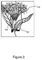
- FIG 3 is a schematic block diagram illustrating a semitransparent viewing experience according to embodiments.
- the electronic device 101 is able to show at least part of the obscured area 108 on the corresponding calculated 203 position on the display 103.
- an object 107 such as a hand 301
- parts of the obscured area 108 is visible on the display 103 giving the semitransparent viewing experience for the user 102.
- the electronic device 101 transfers the image to the display 103 and the display 103 displays it.
- the keyboard the user 102 is typing on will be displayed above the typing fingers. This gives a semitransparent viewing experience for the user.
- Embodiments of a method in the electronic device 101 for displaying content of the obscured area 108 of the view 106 to the user 102 of the electronic device 101 will now be described with reference to a flow chart depicted in figure 4 .
- Figure 4 will be described from the perspective of the electronic device 101.
- the content is displayed on the display 103 comprised in the electronic device 101.
- the display 103 is adapted to be located between the eye 104 of the user 102 and the view 106.
- the method comprises the following actions, which actions may be carried out in any other suitable order than described below. Actions may also be combined.
- the electronic device 101 obtains position information regarding the object 107 from a sensor 109 attached to the object 107 obscuring the view 106. This action corresponds to action 202 in the description relating to the signaling diagram in figure 2 .
- the electronic device 101 obtains information identifying the position of the obscured area 108 in relation to the view 106. This action corresponds to action 201 in the description relating to the signaling diagram in figure 2 .
- the electronic device 101 calculates information identifying the position of the obscured area 108 on the display 103 based on the obtained 201, 402 information identifying the position of the obscured area 108 in relation to the view 106. This action corresponds to action 203 in the description relating to the signaling diagram in figure 2 .
- the electronic device 101 obtains information regarding the content of the view 106 or part of the view 106 when not obscured from a memory 200.
- the memory 200 is connected to the camera 105.
- the camera 105 is arranged on the electronic device 101, wherein the information regarding the content of the view 106 was recorded by the camera 105 and saved on the memory 200 before the view 106 was obscured. This action corresponds to action 205 in the description relating to the signaling diagram in figure 2 .
- the electronic device 101 creates an image relating to the content of the obscured area 108 of the view 106 based on the obtained 402 information identifying the position of the obscured area in relation to the display 103 and based on the calculated 403 information identifying a position of the obscured area 108 in relation to the view 106, and the obtained 404 information regarding the content of the view 106 or part of the view 106 when not obscured.
- This action corresponds to action 206 in the description relating to the signaling diagram in figure 2 .
- the electronic device 101 displays the image on a place on the display 103 that corresponds to the calculated 403 position of the obscured area in relation to the display 103. This action corresponds to action 207 in the description relating to the signaling diagram in figure 2 .
- the electronic device 101 comprises an arrangement depicted in figure 5 .
- the camera 105, the memory 200 and the display 103 will be included in the electronic device 101. It is obvious for the skilled person that these units may be realized as separate units connected to the electronic device 101.
- the electronic device 101 is adapted to display a content of the obscured area 108 of the view 106 of the user 102 of the electronic device 101.
- the content is displayed on the display 103 comprised in the electronic device 101.
- the display 103 is adapted to be located between the eye 104 of the user 102 and the view 106.
- the electronic device 101 further comprises the memory 200 connected to the camera 105 arranged on the electronic device 101.
- the electronic device 101 may be an augmented reality unit.
- the electronic device 101 comprises an obtaining circuitry 501 configured to obtain an information identifying the position of the obscured area 108 in relation to the view 106.
- the obtaining circuitry 501 is connectable to the sensor 109, camera 105 and to the memory 200.
- the information identifying the position of the obscured area 108 in relation to the view 106 may comprise image data.
- the obtaining circuitry 501 is further configured to identify in the image data the object 107 that obscures the view 106.
- the obtaining circuitry 501 may further be configured to obtain position information regarding the object 107 from the sensor 109 attached to the object 107 obscuring the view 106.
- the electronic device 101 further comprises a calculating circuitry 502 configured to calculate the information identifying the position of the obscured area 108 on the display 103, based on the obtained information identifying the position of the obscured area 108 in relation to the view 106.
- the calculating circuitry 502 is connectable to the obtaining circuitry 501.
- the obtaining circuitry 501 is further configured to obtain the information regarding the content of the view 106 or part of the view 106 when not obscured, from the memory 200.
- the information regarding the content of the view 106 was recorded by the camera 105 and saved on the memory 200 before the view 106 was obscured.
- the electronic device 101 further comprises a creating circuitry 503 configured to create the image relating to the content of the obscured area 108 of the view 106 based on the obtained information identifying the position of the obscured area 108 in relation to the display 103 and based on the calculated information identifying a position of the obscured area 108 in relation to the view 106, and based on the obtained information regarding the content of the view 106 or part of the view 106 when not obscured.
- the creating circuitry 503 is connectable to the obtaining circuitry 501 and the calculating circuitry 502.
- the electronic device 101 further comprises a displaying circuitry 504 configured to display the image on a place on the display 103 that corresponds to the calculated position of the obscured area in relation to the display 103.
- the displaying circuitry 504 is connectable to the calculating circuitry 502, the creating circuitry 503 and the display 103.
- the embodiments herein for displaying content of an obscured area 108 in the electronic device 101 may be implemented through one or more processors, such as a processor 505 in the electronic device 101, together with computer program code for performing the functions and actions of the embodiments herein.
- the program code mentioned above may also be provided as a computer program product, for instance in the form of a data carrier carrying computer program code for performing the embodiments herein when being loaded into the electronic device 101.
- a data carrier may be in the form of a CD ROM disc. It is however feasible with other data carriers such as a memory stick.
- the computer program code may furthermore be provided as pure program code on a server and downloaded to the electronic device 101.
- the electronic device 101 may further comprise an external memory 506 comprising one or more memory units.
- the external memory 506 is arranged to be used to store data, received data streams, received information, configurations, schedulings, and applications to perform the methods herein when being executed in the electronic device 101.
- the obtaining circuitry 501, the calculating circuitry 502, the creating circuitry 503 and the displaying circuitry 504 described above may refer to a combination of analog and digital circuits, and/or one or more processors configured with software and/or firmware, e.g. stored in a memory, that when executed by the one or more processors.
- processors may be included in a single application-specific integrated circuit (ASIC), or several processors and various digital hardware may be distributed among several separate components, whether individually packaged or assembled into a system-on-a-chip (SoC).
- ASIC application-specific integrated circuit
- SoC system-on-a-chip
Landscapes
- Engineering & Computer Science (AREA)
- Physics & Mathematics (AREA)
- General Physics & Mathematics (AREA)
- General Engineering & Computer Science (AREA)
- Theoretical Computer Science (AREA)
- Optics & Photonics (AREA)
- Human Computer Interaction (AREA)
- Computer Graphics (AREA)
- Computer Hardware Design (AREA)
- Software Systems (AREA)
- User Interface Of Digital Computer (AREA)
Claims (9)
- Verfahren in einer elektronischen Vorrichtung (101) zur Anzeige von Inhalt eines verdeckten Bereichs (108) einer Ansicht (106) eines Benutzers (102) der elektronischen Vorrichtung (101), wobei der Inhalt auf einer Anzeige (103) angezeigt wird, die in der elektronischen Vorrichtung (101) enthalten ist, wobei die Anzeige (103) so ausgelegt ist, dass sie zwischen einem Auge (104) des Benutzers (102) und der Ansicht (106) angeordnet werden soll, die elektronische Vorrichtung (101) ferner einen Speicher (200) umfasst, der mit einer Kamera (105) verbunden ist, wobei die Kamera (105) auf der elektronischen Vorrichtung (101) angeordnet ist, und das Verfahren umfasst:Beschaffen (201, 402) einer Information, die eine Position des verdeckten Bereichs (108) in Bezug auf die Ansicht (106) identifiziert,Berechnen (203, 403) einer Information, welche die Position des verdeckten Bereichs (108) auf der Anzeige (103) identifiziert, basierend auf der beschafften (201, 402) Information, welche die Position des verdeckten Bereichs (108) in Bezug auf die Ansicht (106) identifiziert,Beschaffen (205, 404) einer Information bezüglich des Inhalts der Ansicht (106) oder eines Teils der Ansicht (106), wenn nicht verdeckt, aus dem Speicher (200), wobei die Information bezüglich des Inhalts der Ansicht (106) durch die Kamera (105) aufgezeichnet und im Speicher (200) gespeichert wurde, bevor die Ansicht (106) verdeckt wurde,Erzeugen (206, 405) eines Bildes in Bezug auf den Inhalt des verdeckten Bereichs (108) der Ansicht (106) basierend auf der beschafften (201, 402) Information, welche die Position des verdeckten Bereichs in Bezug auf die Anzeige (103) identifiziert, und basierend auf der berechneten (203, 403) Information, die eine Position des verdeckten Bereichs (108) in Bezug auf die Ansicht (106) identifiziert, und basierend auf der beschafften (205, 404) Information bezüglich des Inhalts der Ansicht (106) oder eines Teils der Ansicht (106), wenn nicht verdeckt, undAnzeigen (207, 406) des Bildes an einer Stelle auf der Anzeige (103), die der berechneten (203, 403) Position des verdeckten Bereichs in Bezug auf die Anzeige (103) entspricht.
- Verfahren nach Anspruch 1, wobei die Information, welche die Position des verdeckten Bereichs (108) in Bezug auf die Ansicht (106) identifiziert, Bilddaten umfasst, und wobei das Beschaffen (201, 402) der Information, die eine Position des verdeckten Bereichs (108) in Bezug auf die Ansicht (106) identifiziert, ferner ein Identifizieren eines Objekts (107) in den Bilddaten umfasst, das die Ansicht (106) verdeckt.
- Verfahren nach einem der Ansprüche 1 bis 2, wobei das Beschaffen (201, 402) der Information, die eine Position des verdeckten Bereichs (108) in Bezug auf die Ansicht (106) identifiziert, ferner umfasst:Beschaffen (202, 401) von einem Sensor (109), der an einem Objekt (107) angebracht ist, das die Ansicht (106) verdeckt, von Positionsinformationen bezüglich des Objekts (107).
- Verfahren nach einem der Ansprüche 1 bis 3, wobei die elektronische Vorrichtung (101) eine Einheit für erweiterte Realität ist.
- Elektronische Vorrichtung (101) zum Anzeigen eines Inhalts eines verdeckten Bereichs (108) einer Ansicht (106) eines Benutzers (102) der elektronischen Vorrichtung (101), wobei der Inhalt auf einer Anzeige (103) angezeigt wird, die in der elektronischen Vorrichtung (101) enthalten ist, wobei die Anzeige (103) so ausgelegt ist, dass sie zwischen einem Auge (104) des Benutzers (102) und der Ansicht (106) angeordnet werden soll, die elektronische Vorrichtung (101) ferner einen Speicher (200) umfasst, der mit einer Kamera (105) verbunden ist, wobei die Kamera (105) auf der elektronischen Vorrichtung (101) angeordnet ist, und die elektronische Vorrichtung (101) umfasst:eine Beschaffungsschaltungsanordnung (501), die so konfiguriert ist, dass sie eine Information beschafft, die eine Position des verdeckten Bereichs (108) in Bezug auf die Ansicht (106) identifiziert,eine Berechnungsschaltungsanordnung (502), die so konfiguriert ist, dass sie eine Information, welche die Position des verdeckten Bereichs (108) auf der Anzeige (103) identifiziert, basierend auf der beschafften Information berechnet, welche die Position des verdeckten Bereichs (108) in Bezug auf die Ansicht (106) identifiziert,wobei die Beschaffungsschaltungsanordnung (501) ferner so konfiguriert ist, dass sie eine Information bezüglich des Inhalts der Ansicht (106) oder eines Teils der Ansicht (106), wenn nicht verdeckt, aus dem Speicher (200) beschafft, wobei die Information bezüglich des Inhalts der Ansicht (106) durch die Kamera (105) aufgezeichnet und im Speicher (200) gespeichert wurde, bevor die Ansicht (106) verdeckt wurde,eine Erzeugungsschaltungsanordnung (503), die so konfiguriert ist, dass sie ein Bild in Bezug auf den Inhalt des verdeckten Bereichs (108) der Ansicht (106) basierend auf der beschafften Information, welche die Position der verdeckten Bereichs in Bezug auf die Anzeige (103) identifiziert, und basierend auf der berechneten Information, die eine Position des verdeckten Bereichs (108) in Bezug auf die Ansicht (106) identifiziert, und basierend auf der beschafften Information bezüglich des Inhalts der Ansicht (106) oder eines Teils der Ansicht (106), wenn nicht verdeckt, erzeugt, undeine Anzeigeschaltungsanordnung (504), die so konfiguriert ist, dass sie das Bild an einer Stelle auf der Anzeige (103) anzeigt, die der berechneten Position des verdeckten Bereichs in Bezug auf die Anzeige (103) entspricht.
- Elektronische Vorrichtung (101) nach Anspruch 5, wobei die Information, welche die Position des verdeckten Bereichs (108) in Bezug auf die Ansicht (106) identifiziert, Bilddaten umfasst, und wobei Beschaffungsschaltungsanordnung (501) ferner so konfiguriert ist, dass sie ein Objekt (107) in den Bilddaten identifiziert, das die Ansicht (106) verdeckt.
- Elektronische Vorrichtung (101) nach einem der Ansprüche 5 bis 6, wobei die Beschaffungsschaltungsanordnung (501) ferner so konfiguriert ist, dass sie von einem Sensor (109), der an einem Objekt (107) angebracht ist, das die Ansicht (106) verdeckt, Positionsinformationen bezüglich des Objekts (107) beschafft.
- Elektronische Vorrichtung (101) nach einem der Ansprüche 5 bis 7, wobei die elektronische Vorrichtung (101) eine Einheit für erweiterte Realität ist.
- Computerprogrammprodukt, das in einen externen Speicher (506) einer Computervorrichtung geladen werden kann und Softwarecodeabschnitte umfasst, die zum Ausführen der Verfahrensschritte nach Anspruch 1 bis 4 ausgelegt sind.
Applications Claiming Priority (1)
| Application Number | Priority Date | Filing Date | Title |
|---|---|---|---|
| PCT/EP2012/054195 WO2013135262A1 (en) | 2012-03-12 | 2012-03-12 | Electronic device for displaying content of an obscured area of a view |
Publications (2)
| Publication Number | Publication Date |
|---|---|
| EP2825933A1 EP2825933A1 (de) | 2015-01-21 |
| EP2825933B1 true EP2825933B1 (de) | 2016-02-10 |
Family
ID=45811524
Family Applications (1)
| Application Number | Title | Priority Date | Filing Date |
|---|---|---|---|
| EP12707791.5A Active EP2825933B1 (de) | 2012-03-12 | 2012-03-12 | Elektronische vorrichtung zur anzeige von inhalten eines verdeckten sichtbereichs |
Country Status (4)
| Country | Link |
|---|---|
| US (1) | US9024973B2 (de) |
| EP (1) | EP2825933B1 (de) |
| CN (1) | CN104205007B (de) |
| WO (1) | WO2013135262A1 (de) |
Families Citing this family (4)
| Publication number | Priority date | Publication date | Assignee | Title |
|---|---|---|---|---|
| US9406114B2 (en) * | 2014-02-18 | 2016-08-02 | Empire Technology Development Llc | Composite image generation to remove obscuring objects |
| CN104834244A (zh) * | 2014-11-05 | 2015-08-12 | 电子科技大学 | 一种手势开关及手势控制方法 |
| US11023033B2 (en) * | 2019-01-09 | 2021-06-01 | International Business Machines Corporation | Adapting a display of interface elements on a touch-based device to improve visibility |
| CN110009720B (zh) * | 2019-04-02 | 2023-04-07 | 阿波罗智联(北京)科技有限公司 | Ar场景中的图像处理方法、装置、电子设备及存储介质 |
Family Cites Families (7)
| Publication number | Priority date | Publication date | Assignee | Title |
|---|---|---|---|---|
| US20060176242A1 (en) * | 2005-02-08 | 2006-08-10 | Blue Belt Technologies, Inc. | Augmented reality device and method |
| US8531449B2 (en) * | 2007-12-18 | 2013-09-10 | Navteq B.V. | System and method for producing multi-angle views of an object-of-interest from images in an image dataset |
| US8641621B2 (en) * | 2009-02-17 | 2014-02-04 | Inneroptic Technology, Inc. | Systems, methods, apparatuses, and computer-readable media for image management in image-guided medical procedures |
| US20110214082A1 (en) | 2010-02-28 | 2011-09-01 | Osterhout Group, Inc. | Projection triggering through an external marker in an augmented reality eyepiece |
| US9734633B2 (en) * | 2012-01-27 | 2017-08-15 | Microsoft Technology Licensing, Llc | Virtual environment generating system |
| CN104025151B (zh) * | 2012-01-31 | 2018-08-28 | 索尼移动通信株式会社 | 用于创建组合图像的方法和电子装置 |
| US9741166B2 (en) * | 2012-11-24 | 2017-08-22 | Novarad Corporation | Generation and viewing of panoramic images |
-
2012
- 2012-03-12 EP EP12707791.5A patent/EP2825933B1/de active Active
- 2012-03-12 CN CN201280071332.8A patent/CN104205007B/zh active Active
- 2012-03-12 WO PCT/EP2012/054195 patent/WO2013135262A1/en not_active Ceased
- 2012-03-12 US US13/820,272 patent/US9024973B2/en active Active
Also Published As
| Publication number | Publication date |
|---|---|
| US20140160159A1 (en) | 2014-06-12 |
| US9024973B2 (en) | 2015-05-05 |
| CN104205007B (zh) | 2016-11-02 |
| WO2013135262A1 (en) | 2013-09-19 |
| EP2825933A1 (de) | 2015-01-21 |
| CN104205007A (zh) | 2014-12-10 |
Similar Documents
| Publication | Publication Date | Title |
|---|---|---|
| US20240103684A1 (en) | Methods for displaying objects relative to virtual surfaces | |
| US20240094882A1 (en) | Gestures for selection refinement in a three-dimensional environment | |
| US20240403080A1 (en) | Devices, methods, and graphical user interfaces for displaying views of physical locations | |
| US20240404232A1 (en) | Devices, methods, and graphical user interfaces for content applications | |
| US11595637B2 (en) | Systems and methods for using peripheral vision in virtual, augmented, and mixed reality (xR) applications | |
| US20240404207A1 (en) | Devices, methods, and graphical user interfaces for displaying content of physical locations | |
| US12602865B2 (en) | Methods for depth conflict mitigation in a three-dimensional environment | |
| US10928893B2 (en) | Content delivery | |
| ES2759054T3 (es) | Región basada en gestos del cuerpo humano y selección de volumen para HMD | |
| US9497389B2 (en) | Information processing device, information processing method, and program for reduction of noise effects on a reference point | |
| US20110140994A1 (en) | Information Presenting Apparatus, Method, and Computer Program Product | |
| US8847850B1 (en) | Head mounted display device for displaying augmented reality image capture guide and control method for the same | |
| US20190102934A1 (en) | Shadows for inserted content | |
| US11682045B2 (en) | Augmented reality advertisements on objects | |
| CN109074149A (zh) | 用于增强或虚拟现实环境的头戴式参考系中的对象跟踪 | |
| US11100672B2 (en) | System and method for reducing jitter in augmented reality | |
| CN109448050B (zh) | 一种目标点的位置的确定方法及终端 | |
| EP2825933B1 (de) | Elektronische vorrichtung zur anzeige von inhalten eines verdeckten sichtbereichs | |
| EP3627288A1 (de) | Kameramodul und system damit | |
| WO2025255394A1 (en) | Methods of adjusting a simulated resolution of a virtual object in a three-dimensional environment | |
| EP4705862A1 (de) | Vorrichtungen, verfahren und grafische benutzeroberflächen zur präsentation von inhalt | |
| CN113129358A (zh) | 用于呈现虚拟对象的方法和系统 | |
| US20250110569A1 (en) | Devices, Methods, and Graphical User Interfaces for Processing Inputs to a Three-Dimensional Environment | |
| JP7528951B2 (ja) | 表示端末装置 | |
| WO2025072024A1 (en) | Devices, methods, and graphical user interfaces for processing inputs to a three-dimensional environment |
Legal Events
| Date | Code | Title | Description |
|---|---|---|---|
| PUAI | Public reference made under article 153(3) epc to a published international application that has entered the european phase |
Free format text: ORIGINAL CODE: 0009012 |
|
| 17P | Request for examination filed |
Effective date: 20140911 |
|
| AK | Designated contracting states |
Kind code of ref document: A1 Designated state(s): AL AT BE BG CH CY CZ DE DK EE ES FI FR GB GR HR HU IE IS IT LI LT LU LV MC MK MT NL NO PL PT RO RS SE SI SK SM TR |
|
| AX | Request for extension of the european patent |
Extension state: BA ME |
|
| DAX | Request for extension of the european patent (deleted) | ||
| GRAP | Despatch of communication of intention to grant a patent |
Free format text: ORIGINAL CODE: EPIDOSNIGR1 |
|
| RIC1 | Information provided on ipc code assigned before grant |
Ipc: G06T 19/00 20110101ALI20150713BHEP Ipc: G02B 27/01 20060101ALI20150713BHEP Ipc: G06F 3/01 20060101AFI20150713BHEP |
|
| INTG | Intention to grant announced |
Effective date: 20150813 |
|
| GRAS | Grant fee paid |
Free format text: ORIGINAL CODE: EPIDOSNIGR3 |
|
| GRAA | (expected) grant |
Free format text: ORIGINAL CODE: 0009210 |
|
| AK | Designated contracting states |
Kind code of ref document: B1 Designated state(s): AL AT BE BG CH CY CZ DE DK EE ES FI FR GB GR HR HU IE IS IT LI LT LU LV MC MK MT NL NO PL PT RO RS SE SI SK SM TR |
|
| REG | Reference to a national code |
Ref country code: GB Ref legal event code: FG4D |
|
| REG | Reference to a national code |
Ref country code: AT Ref legal event code: REF Ref document number: 774955 Country of ref document: AT Kind code of ref document: T Effective date: 20160215 Ref country code: CH Ref legal event code: EP |
|
| REG | Reference to a national code |
Ref country code: IE Ref legal event code: FG4D |
|
| REG | Reference to a national code |
Ref country code: DE Ref legal event code: R096 Ref document number: 602012014661 Country of ref document: DE |
|
| REG | Reference to a national code |
Ref country code: LT Ref legal event code: MG4D |
|
| REG | Reference to a national code |
Ref country code: NL Ref legal event code: MP Effective date: 20160210 |
|
| REG | Reference to a national code |
Ref country code: AT Ref legal event code: MK05 Ref document number: 774955 Country of ref document: AT Kind code of ref document: T Effective date: 20160210 |
|
| PG25 | Lapsed in a contracting state [announced via postgrant information from national office to epo] |
Ref country code: NO Free format text: LAPSE BECAUSE OF FAILURE TO SUBMIT A TRANSLATION OF THE DESCRIPTION OR TO PAY THE FEE WITHIN THE PRESCRIBED TIME-LIMIT Effective date: 20160510 Ref country code: HR Free format text: LAPSE BECAUSE OF FAILURE TO SUBMIT A TRANSLATION OF THE DESCRIPTION OR TO PAY THE FEE WITHIN THE PRESCRIBED TIME-LIMIT Effective date: 20160210 Ref country code: ES Free format text: LAPSE BECAUSE OF FAILURE TO SUBMIT A TRANSLATION OF THE DESCRIPTION OR TO PAY THE FEE WITHIN THE PRESCRIBED TIME-LIMIT Effective date: 20160210 Ref country code: GR Free format text: LAPSE BECAUSE OF FAILURE TO SUBMIT A TRANSLATION OF THE DESCRIPTION OR TO PAY THE FEE WITHIN THE PRESCRIBED TIME-LIMIT Effective date: 20160511 Ref country code: IT Free format text: LAPSE BECAUSE OF FAILURE TO SUBMIT A TRANSLATION OF THE DESCRIPTION OR TO PAY THE FEE WITHIN THE PRESCRIBED TIME-LIMIT Effective date: 20160210 Ref country code: FI Free format text: LAPSE BECAUSE OF FAILURE TO SUBMIT A TRANSLATION OF THE DESCRIPTION OR TO PAY THE FEE WITHIN THE PRESCRIBED TIME-LIMIT Effective date: 20160210 |
|
| PG25 | Lapsed in a contracting state [announced via postgrant information from national office to epo] |
Ref country code: IS Free format text: LAPSE BECAUSE OF FAILURE TO SUBMIT A TRANSLATION OF THE DESCRIPTION OR TO PAY THE FEE WITHIN THE PRESCRIBED TIME-LIMIT Effective date: 20160610 Ref country code: SE Free format text: LAPSE BECAUSE OF FAILURE TO SUBMIT A TRANSLATION OF THE DESCRIPTION OR TO PAY THE FEE WITHIN THE PRESCRIBED TIME-LIMIT Effective date: 20160210 Ref country code: NL Free format text: LAPSE BECAUSE OF FAILURE TO SUBMIT A TRANSLATION OF THE DESCRIPTION OR TO PAY THE FEE WITHIN THE PRESCRIBED TIME-LIMIT Effective date: 20160210 Ref country code: RS Free format text: LAPSE BECAUSE OF FAILURE TO SUBMIT A TRANSLATION OF THE DESCRIPTION OR TO PAY THE FEE WITHIN THE PRESCRIBED TIME-LIMIT Effective date: 20160210 Ref country code: BE Free format text: LAPSE BECAUSE OF NON-PAYMENT OF DUE FEES Effective date: 20160331 Ref country code: PL Free format text: LAPSE BECAUSE OF FAILURE TO SUBMIT A TRANSLATION OF THE DESCRIPTION OR TO PAY THE FEE WITHIN THE PRESCRIBED TIME-LIMIT Effective date: 20160210 Ref country code: AT Free format text: LAPSE BECAUSE OF FAILURE TO SUBMIT A TRANSLATION OF THE DESCRIPTION OR TO PAY THE FEE WITHIN THE PRESCRIBED TIME-LIMIT Effective date: 20160210 Ref country code: PT Free format text: LAPSE BECAUSE OF FAILURE TO SUBMIT A TRANSLATION OF THE DESCRIPTION OR TO PAY THE FEE WITHIN THE PRESCRIBED TIME-LIMIT Effective date: 20160613 Ref country code: LV Free format text: LAPSE BECAUSE OF FAILURE TO SUBMIT A TRANSLATION OF THE DESCRIPTION OR TO PAY THE FEE WITHIN THE PRESCRIBED TIME-LIMIT Effective date: 20160210 Ref country code: LT Free format text: LAPSE BECAUSE OF FAILURE TO SUBMIT A TRANSLATION OF THE DESCRIPTION OR TO PAY THE FEE WITHIN THE PRESCRIBED TIME-LIMIT Effective date: 20160210 |
|
| PG25 | Lapsed in a contracting state [announced via postgrant information from national office to epo] |
Ref country code: DK Free format text: LAPSE BECAUSE OF FAILURE TO SUBMIT A TRANSLATION OF THE DESCRIPTION OR TO PAY THE FEE WITHIN THE PRESCRIBED TIME-LIMIT Effective date: 20160210 Ref country code: EE Free format text: LAPSE BECAUSE OF FAILURE TO SUBMIT A TRANSLATION OF THE DESCRIPTION OR TO PAY THE FEE WITHIN THE PRESCRIBED TIME-LIMIT Effective date: 20160210 |
|
| REG | Reference to a national code |
Ref country code: CH Ref legal event code: PL |
|
| REG | Reference to a national code |
Ref country code: DE Ref legal event code: R097 Ref document number: 602012014661 Country of ref document: DE |
|
| PG25 | Lapsed in a contracting state [announced via postgrant information from national office to epo] |
Ref country code: CZ Free format text: LAPSE BECAUSE OF FAILURE TO SUBMIT A TRANSLATION OF THE DESCRIPTION OR TO PAY THE FEE WITHIN THE PRESCRIBED TIME-LIMIT Effective date: 20160210 Ref country code: RO Free format text: LAPSE BECAUSE OF FAILURE TO SUBMIT A TRANSLATION OF THE DESCRIPTION OR TO PAY THE FEE WITHIN THE PRESCRIBED TIME-LIMIT Effective date: 20160210 Ref country code: SM Free format text: LAPSE BECAUSE OF FAILURE TO SUBMIT A TRANSLATION OF THE DESCRIPTION OR TO PAY THE FEE WITHIN THE PRESCRIBED TIME-LIMIT Effective date: 20160210 Ref country code: SK Free format text: LAPSE BECAUSE OF FAILURE TO SUBMIT A TRANSLATION OF THE DESCRIPTION OR TO PAY THE FEE WITHIN THE PRESCRIBED TIME-LIMIT Effective date: 20160210 |
|
| PLBE | No opposition filed within time limit |
Free format text: ORIGINAL CODE: 0009261 |
|
| STAA | Information on the status of an ep patent application or granted ep patent |
Free format text: STATUS: NO OPPOSITION FILED WITHIN TIME LIMIT |
|
| REG | Reference to a national code |
Ref country code: IE Ref legal event code: MM4A |
|
| PG25 | Lapsed in a contracting state [announced via postgrant information from national office to epo] |
Ref country code: BE Free format text: LAPSE BECAUSE OF FAILURE TO SUBMIT A TRANSLATION OF THE DESCRIPTION OR TO PAY THE FEE WITHIN THE PRESCRIBED TIME-LIMIT Effective date: 20160210 |
|
| REG | Reference to a national code |
Ref country code: FR Ref legal event code: ST Effective date: 20161130 |
|
| 26N | No opposition filed |
Effective date: 20161111 |
|
| GBPC | Gb: european patent ceased through non-payment of renewal fee |
Effective date: 20160510 |
|
| PG25 | Lapsed in a contracting state [announced via postgrant information from national office to epo] |
Ref country code: FR Free format text: LAPSE BECAUSE OF NON-PAYMENT OF DUE FEES Effective date: 20160411 Ref country code: CH Free format text: LAPSE BECAUSE OF NON-PAYMENT OF DUE FEES Effective date: 20160331 Ref country code: IE Free format text: LAPSE BECAUSE OF NON-PAYMENT OF DUE FEES Effective date: 20160312 Ref country code: LI Free format text: LAPSE BECAUSE OF NON-PAYMENT OF DUE FEES Effective date: 20160331 |
|
| PG25 | Lapsed in a contracting state [announced via postgrant information from national office to epo] |
Ref country code: BG Free format text: LAPSE BECAUSE OF FAILURE TO SUBMIT A TRANSLATION OF THE DESCRIPTION OR TO PAY THE FEE WITHIN THE PRESCRIBED TIME-LIMIT Effective date: 20160510 Ref country code: SI Free format text: LAPSE BECAUSE OF FAILURE TO SUBMIT A TRANSLATION OF THE DESCRIPTION OR TO PAY THE FEE WITHIN THE PRESCRIBED TIME-LIMIT Effective date: 20160210 |
|
| PG25 | Lapsed in a contracting state [announced via postgrant information from national office to epo] |
Ref country code: GB Free format text: LAPSE BECAUSE OF NON-PAYMENT OF DUE FEES Effective date: 20160510 |
|
| PG25 | Lapsed in a contracting state [announced via postgrant information from national office to epo] |
Ref country code: MT Free format text: LAPSE BECAUSE OF FAILURE TO SUBMIT A TRANSLATION OF THE DESCRIPTION OR TO PAY THE FEE WITHIN THE PRESCRIBED TIME-LIMIT Effective date: 20160210 |
|
| PG25 | Lapsed in a contracting state [announced via postgrant information from national office to epo] |
Ref country code: HU Free format text: LAPSE BECAUSE OF FAILURE TO SUBMIT A TRANSLATION OF THE DESCRIPTION OR TO PAY THE FEE WITHIN THE PRESCRIBED TIME-LIMIT; INVALID AB INITIO Effective date: 20120312 |
|
| PG25 | Lapsed in a contracting state [announced via postgrant information from national office to epo] |
Ref country code: CY Free format text: LAPSE BECAUSE OF FAILURE TO SUBMIT A TRANSLATION OF THE DESCRIPTION OR TO PAY THE FEE WITHIN THE PRESCRIBED TIME-LIMIT Effective date: 20160210 Ref country code: LU Free format text: LAPSE BECAUSE OF NON-PAYMENT OF DUE FEES Effective date: 20160312 Ref country code: MT Free format text: LAPSE BECAUSE OF FAILURE TO SUBMIT A TRANSLATION OF THE DESCRIPTION OR TO PAY THE FEE WITHIN THE PRESCRIBED TIME-LIMIT Effective date: 20160331 Ref country code: MC Free format text: LAPSE BECAUSE OF FAILURE TO SUBMIT A TRANSLATION OF THE DESCRIPTION OR TO PAY THE FEE WITHIN THE PRESCRIBED TIME-LIMIT Effective date: 20160210 Ref country code: MK Free format text: LAPSE BECAUSE OF FAILURE TO SUBMIT A TRANSLATION OF THE DESCRIPTION OR TO PAY THE FEE WITHIN THE PRESCRIBED TIME-LIMIT Effective date: 20160210 |
|
| PG25 | Lapsed in a contracting state [announced via postgrant information from national office to epo] |
Ref country code: TR Free format text: LAPSE BECAUSE OF FAILURE TO SUBMIT A TRANSLATION OF THE DESCRIPTION OR TO PAY THE FEE WITHIN THE PRESCRIBED TIME-LIMIT Effective date: 20160210 Ref country code: AL Free format text: LAPSE BECAUSE OF FAILURE TO SUBMIT A TRANSLATION OF THE DESCRIPTION OR TO PAY THE FEE WITHIN THE PRESCRIBED TIME-LIMIT Effective date: 20160210 |
|
| P01 | Opt-out of the competence of the unified patent court (upc) registered |
Effective date: 20230527 |
|
| PGFP | Annual fee paid to national office [announced via postgrant information from national office to epo] |
Ref country code: DE Payment date: 20260219 Year of fee payment: 15 |