EP2825924B1 - Mmi for uav control - Google Patents
Mmi for uav control Download PDFInfo
- Publication number
- EP2825924B1 EP2825924B1 EP13702414.7A EP13702414A EP2825924B1 EP 2825924 B1 EP2825924 B1 EP 2825924B1 EP 13702414 A EP13702414 A EP 13702414A EP 2825924 B1 EP2825924 B1 EP 2825924B1
- Authority
- EP
- European Patent Office
- Prior art keywords
- aircraft
- pair
- symbol
- speed
- effecting
- Prior art date
- Legal status (The legal status is an assumption and is not a legal conclusion. Google has not performed a legal analysis and makes no representation as to the accuracy of the status listed.)
- Active
Links
Images
Classifications
-
- B—PERFORMING OPERATIONS; TRANSPORTING
- B64—AIRCRAFT; AVIATION; COSMONAUTICS
- B64C—AEROPLANES; HELICOPTERS
- B64C19/00—Aircraft control not otherwise provided for
-
- G—PHYSICS
- G05—CONTROLLING; REGULATING
- G05D—SYSTEMS FOR CONTROLLING OR REGULATING NON-ELECTRIC VARIABLES
- G05D1/00—Control of position, course, altitude or attitude of land, water, air or space vehicles, e.g. using automatic pilots
- G05D1/0011—Control of position, course, altitude or attitude of land, water, air or space vehicles, e.g. using automatic pilots associated with a remote control arrangement
- G05D1/0016—Control of position, course, altitude or attitude of land, water, air or space vehicles, e.g. using automatic pilots associated with a remote control arrangement characterised by the operator's input device
-
- G—PHYSICS
- G05—CONTROLLING; REGULATING
- G05D—SYSTEMS FOR CONTROLLING OR REGULATING NON-ELECTRIC VARIABLES
- G05D1/00—Control of position, course, altitude or attitude of land, water, air or space vehicles, e.g. using automatic pilots
- G05D1/0011—Control of position, course, altitude or attitude of land, water, air or space vehicles, e.g. using automatic pilots associated with a remote control arrangement
- G05D1/0038—Control of position, course, altitude or attitude of land, water, air or space vehicles, e.g. using automatic pilots associated with a remote control arrangement by providing the operator with simple or augmented images from one or more cameras located onboard the vehicle, e.g. tele-operation
-
- G—PHYSICS
- G06—COMPUTING OR CALCULATING; COUNTING
- G06F—ELECTRIC DIGITAL DATA PROCESSING
- G06F3/00—Input arrangements for transferring data to be processed into a form capable of being handled by the computer; Output arrangements for transferring data from processing unit to output unit, e.g. interface arrangements
- G06F3/01—Input arrangements or combined input and output arrangements for interaction between user and computer
- G06F3/048—Interaction techniques based on graphical user interfaces [GUI]
- G06F3/0484—Interaction techniques based on graphical user interfaces [GUI] for the control of specific functions or operations, e.g. selecting or manipulating an object, an image or a displayed text element, setting a parameter value or selecting a range
- G06F3/04842—Selection of displayed objects or displayed text elements
Definitions
- the embodiments herein relate to controlling an Unmanned Aerial Vehicle (UAV).
- UAV Unmanned Aerial Vehicle
Landscapes
- Engineering & Computer Science (AREA)
- Physics & Mathematics (AREA)
- Radar, Positioning & Navigation (AREA)
- Remote Sensing (AREA)
- Aviation & Aerospace Engineering (AREA)
- General Physics & Mathematics (AREA)
- Theoretical Computer Science (AREA)
- Automation & Control Theory (AREA)
- General Engineering & Computer Science (AREA)
- Mathematical Physics (AREA)
- Computing Systems (AREA)
- Human Computer Interaction (AREA)
- Mechanical Control Devices (AREA)
- Traffic Control Systems (AREA)
- Toys (AREA)
- Switches With Compound Operations (AREA)
- Selective Calling Equipment (AREA)
Description
- The embodiments herein relate to controlling an Unmanned Aerial Vehicle (UAV).
- Modern warfare and law enforcement are characterized by an increasing need for up-to-date situational awareness. To track down, or to protect against, criminals, paramilitary forces or terrorists, law enforcement personnel and soldiers often have an immediate need for information about what is around the next corner or over the hill.
- Hostile forces frequently hide themselves from view or exploit the local terrain to gain tactical advantage or escape from pursuers. In the presence of hostile forces, a simple brick wall, barbed wire fence, a body of water, buildings or even a large open area can be an insurmountable obstacle when time is of the essence and tactical resources are unavailable. An active or undetected threat can make the situation dangerous.
- Visible indications, noises or predictable actions can reveal friendly forces and put them at risk. Stealth and surprise, however, are important elements that can give a tactical advantage. An Unmanned Aerial Vehicles (UAV) is an aircraft with no pilot on board. UAVs can be remote controlled aircraft (e.g. flown by a pilot at a ground control station) or can fly autonomously based on pre-programmed flight plans or more complex dynamic automation systems. An UAV may also be referred to as a drone. UAVs equipped with video cameras that transmit back live pictures allows their operator to perform surveillance tasks and gather information from a safe position without exposing themselves.
- Traditionally an UAV is operated by a joystick. Most joysticks are two-dimensional, having two axes of movement (similar to a mouse), but one and three-dimensional joysticks do exist. A joystick is generally configured so that moving the stick left or right signals movement along the X axis, and moving it forward (up) or back (down) signals movement along the Y axis. In joysticks that are configured for three-dimensional movement, twisting the stick left (counter-clockwise) or right (clockwise) signals movement along the Z axis. These three axes - X Y and Z - are, in relation to an aircraft, roll, pitch, and yaw.
- A traditional joystick has a joint connected to a base, where the movements of the joystick relative to the base impact the movements of the aircraft correspondingly. The position of the joystick gives the operator feedback of the current control signal impact on the aircraft.
- However, small drones adjusted to be controlled by operational personnel in the fields will typically be stored in UAV kits with limited space, and a traditional joystick with a joint would not be applicable because it would require too much space and the joint would be a weak point exposed to damages when operated in the field. For being operated properly, the base of a traditional joystick should be placed horizontally and stationary, which would not be applicable for a portable remote operating in the field. A one-hand joystick would in this case be more applicable with buttons on the joystick head with pairs of buttons controlling the forward/backward speed (pitch), left/right speed (roll) and left/right rotation (yaw) respectively. However, the spatial position of the joystick would in this case not give feedback to the operator about current commended speed. Thus, there is need for a feedback system for controlling an UAV not requiring a joint being independent of the spatial position of the joystick.
-
US 2010/084513 A1 discloses a method of remotely controlling an aerial vehicle within an environment. The presented solution discuss a remote control for controlling an aircraft that comprise a control with a pair of opposite effecting buttons adjusted to stepwise shifting the directional speed of the aircraft. Further,US 2010/084513 A1 discloses a graphical user interface (GUI) adjusted to display steering control status of the aircraft by means of a directional speed symbol. The directional speed symbol and position is depending on the current steering control status. -
EP 2256571 A2 discloses a method for semi-automatic operation of a portable control device for a remote-controlled, unmanned vehicle. The method includes the steps of monitoring parameters of an operational environment of the portable control device, switching from a manual operation mode to a semi-automatic operation mode in response to occurrence of predetermined criteria within the operational environment.EP 2256571 A2 further discloses a GUI whereby arrows located on each side of a centrally located vehicle icon gives an indication of the magnitude of the longitudinal speed and transversal speed corresponding to the speed command sent to the remote aircraft. - The scope of the present invention is defined by independent claims 1 and 4. Embodiments are stated in dependent claims 2-3 and 5-6.
- An object of embodiments herein is therefore to provide an improved remote control for controlling an aircraft. According to a first aspect, the object is achieved by a method for displaying steering control status of an aircraft on a display by means of an aircraft symbol and a number of directional speed symbols, wherein the aircraft symbol is
shaped to indicate the longitudinal and lateral axis passing through origin of the aircraft symbol and the forward direction of the aircraft, and the directional speed is stepwise shifted by a pair of opposite effecting buttons on a control device, including the steps of displaying one or more directional speed symbols positioned on the longitudinal or lateral axis or between two the longitudinal or lateral axis, wherein the number of directional speed symbols and position relative to the aircraft symbol is depending on current steering control status, and when pushing one of the pair of opposite effecting buttons, adding or removing one of the directional speed symbols. - The directional speed symbols may be bars and the aircraft symbol may be an airplane symbol seen from above where an airplane nose on the plane symbol indicates the forward direction of the aircraft.
- In some embodiments, one push on a first button of the pair of opposite effecting buttons generates a speed shift in the forward direction of the aircraft, one push on a second button of the pair of opposite effecting buttons generates a speed shift in the backward direction of the aircraft. The bars may be positioned on said longitudinal axis, and the directional speed that the respective bars represent may be increasing with the distance of the bar's position to the origin.
- In some embodiments, one push on a first button of the pair of opposite effecting buttons generates a speed shift in the left direction of the aircraft, one push on a second button of the pair of opposite effecting buttons generates a speed shift in the right direction of the aircraft. The bars may be positioned on said lateral axis, and the directional speed that the respective bars represent may be increasing with the distance of the bar's position to the origin.
- In some embodiments, one push on a first button of the pair of opposite effecting buttons generates a rotational speed shift in the clockwise direction of the aircraft, one push on a second button of the pair of opposite effecting buttons generates a rotational speed shift in the counterclockwise direction of the aircraft and the bars may be positioned between said lateral and longitudinal axis.
- According to a second aspect, the object is achieved by a remote control for controlling an aircraft comprising a control stick with a pair of opposite effecting buttons adjusted to stepwise shifting the directional speed and a graphical user interface, GUI, adjusted to display steering control status of the aircraft by means of an aircraft symbol and a number of directional speed symbols, wherein the aircraft symbol is shaped to indicate the longitudinal and lateral axis passing through origin of the aircraft symbol and the forward direction of the aircraft, wherein the GUI is further adjusted to display one or more directional speed symbols positioned on the longitudinal or lateral axis or between the longitudinal or lateral axis, wherein the number of directional speed symbols and position relative to the aircraft symbol is depending on current steering control status, and to add or remove one of the directional speed symbols when one of the pair of opposite effecting buttons are activated.
- The directional speed symbols may be bars and the aircraft symbol may an airplane symbol seen from above where an airplane nose on the plane symbol indicates the forward direction of the aircraft.
- In some embodiments, one push on a first button of the pair of opposite effecting buttons generates a speed shift in the forward direction of the aircraft, one push on a second button of the pair of opposite effecting buttons generates a speed shift in the backward direction of the aircraft. The bars may be positioned on said longitudinal axis, and the directional speed that the respective bars represent may be increasing with the distance of the bar's position to the origin.
- In some embodiments, one push on a first button of the pair of opposite effecting buttons generates a speed shift in the left direction of the aircraft, one push on a second button of the pair of opposite effecting buttons generates a speed shift in the right direction of the aircraft. The bars may be positioned on said lateral axis, and the directional speed that the respective bars represent may be increasing with the distance of the bar's position to the origin.
- In some embodiments, one push on a first button of the pair of opposite effecting buttons generates a rotational speed shift in the clockwise direction of the aircraft, one push on a second button of the pair of opposite effecting buttons generates a rotational speed shift in the counterclockwise direction of the aircraft and the bars are positioned between said lateral and longitudinal axis.
- Embodiments herein afford many advantages, of which a non-exhaustive list of examples follows:
An advantage of the embodiments herein is that the remote control is robust, it does not require a large amount of maintenance. Another advantage is that the remote control according to the embodiments herein is easy to use. - The embodiments herein are not limited to the features and advantages mentioned above. A person skilled in the art will recognize additional features and advantages upon reading the following detailed description.
- The following detailed description of the embodiments herein is accompanied by drawings in order to make it more readily understandable. In the drawings:
-
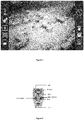
Figure 1 shows a snapshot of a Graphical User Interface (GUI) with an example of a current commanded speed symbol according to the embodiments herein, -
Figure 2 shows an example of a joystick head used in connection with the embodiments herein. - The drawings are not necessarily to scale and the dimensions of certain features may have been exaggerated for the sake of clarity. Emphasis is instead placed upon illustrating the principle of the embodiments herein.
- In the following, the embodiments herein will be discussed and example embodiments described by referring to the accompanying drawings.
- The embodiments herein disclose a remote control stick for controlling an UAV formed by a bar with buttons on the bar head and airplane like icons on a display providing feedback of current impact of the UAV.
-
Figure 1 shows a snapshot of an example GUI comprising a video picture captured by a camera comprised in an UAV (not shown) and different navigation and information symbols on both sides. The upper left symbol indicates the state of the current control signal corresponding to the series of pushes on the different control buttons on a control stick, as exemplified infigure 2 . - The embodiments herein replace the traditional operator feedback of current directional control signal in terms of the position of the joystick with a symbol on a GUI screen. The symbol comprises a static part, e.g. formed as an aircraft and a number of dynamic bars positioned and appearing according to current steering control status associated with activation of buttons on the control stick. Different combinations of activation or pushes on one or several buttons corresponding to give the UAV commands to use a certain directional speed respectively correspond to a specific version of the symbol shown on the screen, which intuitively will give the operator of the remote control information about the current commanded speed given to the UAV. The variations of the symbol mainly effect the number of bars in front of, behind, to the left and to the right of the center symbol. Pairs of buttons on the joystick may offset each other, so that e.g. one push on the left button will cancel the effect of one previous push on the right button, and a possible bar on the right side of the center symbol will be removed. The back and forward button will have the same relation, and also possible rotation left and rotation right button.
- Table 1 shows examples of bars at full deflection corresponding to respective directional speed options when buttons on the remote control is activated. Row 1 represents activation of the forward button 203 which transmits a command of forward speed to the UAV, and the symbol shows a commanded speed at maximum forward ground speed. In this example, the two first bars each represent one sixth of maximum forward speed, while the third and the fourth bar represent one third of maximum forward speed as disclosed in the right column. At maximum forward speed the symbol will show four bars in front of the center symbol positioned on the longitudinal axis of the symbol, which in this case is a plane seen from above. The number of bars and the associated additional commanded left and right sideway speed is disclosed in row 2 and 3. The bars of the left and right sideway speed are positioned on the lateral axis of the symbol. Row 4 discloses the bars associated with commanded left rotation. These bars are located between 9 and 12 o'clock in a clockwise relation to the plane, i.e. between the longitudinal and lateral axis of the symbol. Each bar represents 10 degrees per second. The corresponding bars for the commanded right rotation are disclosed in row 5, and are located between 12 and 15 o'clock in a clockwise relation to the plane. Row 6 discloses the commanded backward speed, and row 7 discloses the symbol for an UAV in hover, with no commanded speed in any direction, which would be the initial situation at flight start-up.
Table 1 Symbol Term Description 
Commanded Forward Speed Commanded forward ground speed. • 1 bar: Max fw speed/6 • 2 bars: Max fw speed/3 • 3 bars: 2*Max fw speed/3 • 4 bars: Max fw speed 
Commanded Left Sideways Speed Commanded left sideways ground speed. • 1 bar: 0.5 m/s (1 kts) • 2 bars: 1 m/s (2 kts) 
Commanded Right Sideways Speed Commanded right sideways ground speed. • 1 bar: 0.5 m/s (1 kts) • 2 bars: 1 m/s (2 kts) 
Commanded Left Rotation Commanded left rotation. • 1 bar: 10°/s • 2bars:20°/s • 3 bars: 30°/s 
Commanded Right Rotation Commanded right rotation. • 1 bar: 10°/s • 2bars:20°/s • 3 bars: 30°/s 
Commanded Backward Speed Commanded backwards ground speed. • 1 bar: 1 m/s (2 kts) 
Hover (no commanded speed) No commanded speed in any direction. NUAV will maintain current GPS position. - The directionally independent symbols illustrated in table 1 can of course be combined according to the different commanded speeds currently applied on the UAV. Table 2 illustrates three examples of such combinations. Row 1 shows an example of the symbol with bars corresponding to 2*Max fw speed/3 and 0.5 m/s (1 kts) right sideways ground speed. Row 2 shows an example of the symbol with bars corresponding to 0.5 m/s (4 kts) left sideway ground speed and 30°/s right rotation, while row 3 represents the symbol at 0.5 m/s (1 kts) left sideways ground speed and 30°/s left rotation. All different combinations of the symbol representing amounts of sideway speeds, backward/forward speed and left/right rotation speed are imaginable, and can be derived from table 1 and the above discussions.
Table 2 Symbol Term Description 
Commanded Forward Speed and Right Sideways Speed • 2*Max fw speed/3 • 0.5 m/s (1 kts) right sideways ground speed 
Commanded Left Sideways Speed and Right Rotation • 0.5 m/s (1 kts) left sideways ground speed • 30°/s right rotation 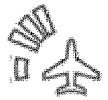
Commanded Right Sideways Speed and Left Rotation • 0.5 m/s (1 kts) left sideways ground speed • 30°/s left rotation - As already indicated, there are different button combinations starting from the hover state leading to the same commanded speed state and corresponding symbol. Table 3 shows one example of a series of button pushes leading to the state shown in row 1 of table 2:
Table 3 Symbol Button State 
Initial state Zero speed in all directions 
Forward • Max fw speed/6 
Forward • Max fw speed/3 
Left • Max fw speed/3 • 0.5 m/s (1 kts) left sideways ground speed 
Right • Max fw speed/3 
Right • Max fw speed/3 • 0.5 m/s (1 kts) right sideways ground speed 
Forward • 2*Max fw speed/3 • 0.5 m/s (1 kts) right sideways ground speed - The above description discloses different examples of the present invention for illustrative purposes. A person skilled in the art would realize a variety of different combinations of symbols, symbol designs and corresponding button series all being within the scope of the present invention.
- It should be emphasized that the term "comprises/comprising" when used in this specification is taken to specify the presence of stated features, integers, steps or components, but does not preclude the presence or addition of one or more other features, integers, steps, components or groups thereof. It should also be noted that the words "a" or "an" preceding an element do not exclude the presence of a plurality of such elements.
- It should also be emphasised that the steps of the methods defined in the appended claims may, without departing from the embodiments herein, be performed in another order than the order in which they appear in the claims.
Claims (6)
- A method for controlling an aircraft with a remote control displaying steering control status of the aircraft on a display by means of an aircraft symbol and a number of directional speed symbols, wherein a directional speed is stepwise shifted by at least one pair of opposite effecting buttons on the remote control, the method comprises:
displaying one or more of the directional speed symbols positioned on a longitudinal axis of the aircraft symbol, on a lateral axis of the aircraft symbol or between the longitudinal axis of the aircraft symbol and the lateral axis of the aircraft symbol, the number of directional speed symbols and position relative to the aircraft symbol depending on a current steering control status,
characterized in that
the method further comprises:when pushing at least one button of the at least one pair of opposite effecting buttons, adding or removing at least one of the directional speed symbols,wherein the aircraft symbol is shaped to indicate the longitudinal axis and the lateral axis passing through an origin of the aircraft symbol and a forward direction of the aircraft,wherein the directional speed symbols are bars and the aircraft symbol comprises an airplane symbol seen from above, wherein an airplane nose on the airplane symbol indicates the forward direction of the aircraft, andwherein a push on a first button of a first pair of the at least one pair of opposite effecting buttons generates a speed shift in the forward direction of the aircraft, a push on a second button of the first pair of the at least one pair of opposite effecting buttons generates a speed shift in a backward direction of the aircraft, the bars are positioned on the longitudinal axis of the aircraft symbol, and the directional speed that respective bars represent is increasing with a distance of the bar's position from the origin of the aircraft symbol along the longitudinal axis. - A method according to claim 1, characterized in that a push on a first button of a second pair of the at least one pair of opposite effecting buttons generates a speed shift in a left direction of the aircraft, a push on a second button of the second pair of the at least one pair of opposite effecting buttons generates a speed shift in a right direction of the aircraft, the bars are positioned on the lateral axis of the aircraft symbol, and the directional speed that the respective bars represent is increasing with a distance of the bar's position from the origin of the aircraft symbol along the lateral axis.
- A method according to claim 1, characterized in that a push on a first button of a third pair of the at least one pair of opposite effecting buttons generates a rotational speed shift in a clockwise direction of the aircraft, a push on a second button of the third pair of the at least one pair of opposite effecting buttons generates a rotational speed shift in a counterclockwise direction of the aircraft, and the bars are positioned between the lateral axis of the aircraft symbol and the longitudinal axis of the aircraft symbol.
- A remote control for controlling an aircraft comprising a control device with at least one pair of opposite effecting buttons configured to stepwise shift a directional speed of the aircraft, and a graphical user interface, GUI, configured to display a steering control status of the aircraft by an aircraft symbol and a number of directional speed symbols, wherein the GUI is further configured to:display one or more directional speed symbols positioned on a longitudinal axis of the aircraft symbol, on a lateral axis of the aircraft symbol or between the longitudinal axis and the lateral axis, wherein the number of directional speed symbols being displayed and positions of the directional speed symbols relative to the aircraft symbol is dependent on a current steering control status,
characterized in thatthe GUI is further configured to add or remove at least one of the directional speed symbols when one of the at least one pair of opposite effecting buttons is activated,wherein the aircraft symbol is shaped to indicate the longitudinal axis and the lateral axis each passing through an origin of the aircraft symbol and a forward direction of the aircraft,wherein the directional speed symbols are configured as bars and the aircraft symbol is configured as an airplane symbol seen from above, wherein an airplane nose on the airplane symbol indicates the forward direction of the aircraft, andwherein a push on a first button of a first pair of the at least one pair of opposite effecting buttons generates a speed shift in the forward direction of the aircraft, a push on a second button of the first pair of the at least one pair of opposite effecting buttons generates a speed shift in a backward direction of the aircraft, the bars are positioned on the longitudinal axis of the aircraft symbol, and a directional speed that respective bars represent increases with a distance of the bar's position from the origin of the aircraft symbol along the longitudinal axis. - A remote control according to claim 4, characterized in that a push on a first button of a second pair of the at least one pair of opposite effecting buttons generates a speed shift in a left direction of the aircraft, a push on a second button of the second pair of the at least one pair of opposite effecting buttons generates a speed shift in a right direction of the aircraft, the bars are positioned on the lateral axis, and the directional speed that the respective bars represent increases with the distance of the bar's position from the origin of the aircraft symbol along the lateral axis.
- A remote control according to claim 4, characterized in that a push on a first button of a third pair of the at least one pair of opposite effecting buttons generates a rotational speed shift in a clockwise direction of the aircraft, a push on a second button of the third pair of the at least one pair of opposite effecting buttons generates a rotational speed shift in a counterclockwise direction of the aircraft and the bars are positioned between the lateral axis of the aircraft symbol and the longitudinal axis of the aircraft symbol.
Applications Claiming Priority (2)
| Application Number | Priority Date | Filing Date | Title |
|---|---|---|---|
| NO20120297A NO334182B1 (en) | 2012-03-14 | 2012-03-14 | UAV control |
| PCT/EP2013/051489 WO2013135410A1 (en) | 2012-03-14 | 2013-01-25 | Mmi for uav control |
Publications (2)
| Publication Number | Publication Date |
|---|---|
| EP2825924A1 EP2825924A1 (en) | 2015-01-21 |
| EP2825924B1 true EP2825924B1 (en) | 2019-09-18 |
Family
ID=47633035
Family Applications (1)
| Application Number | Title | Priority Date | Filing Date |
|---|---|---|---|
| EP13702414.7A Active EP2825924B1 (en) | 2012-03-14 | 2013-01-25 | Mmi for uav control |
Country Status (4)
| Country | Link |
|---|---|
| US (1) | US8886368B2 (en) |
| EP (1) | EP2825924B1 (en) |
| NO (1) | NO334182B1 (en) |
| WO (1) | WO2013135410A1 (en) |
Families Citing this family (10)
| Publication number | Priority date | Publication date | Assignee | Title |
|---|---|---|---|---|
| US8818572B1 (en) * | 2013-03-15 | 2014-08-26 | State Farm Mutual Automobile Insurance Company | System and method for controlling a remote aerial device for up-close inspection |
| US9676472B2 (en) * | 2013-08-30 | 2017-06-13 | Insitu, Inc. | Systems and methods for configurable user interfaces |
| KR20160058471A (en) * | 2014-11-17 | 2016-05-25 | 엘지전자 주식회사 | Mobile device and method for controlling the same |
| JP5831893B1 (en) * | 2015-05-07 | 2015-12-09 | 立 寺坂 | Aircraft remote control system |
| CN105278538B (en) * | 2015-11-24 | 2017-11-07 | 深圳飞马机器人科技有限公司 | A kind of no-manned machine distant control device and method indicated with heading |
| CN106909163A (en) * | 2015-12-22 | 2017-06-30 | 深圳信息职业技术学院 | Immersive VR unmanned plane control loop |
| ES2850364T3 (en) | 2016-02-26 | 2021-08-27 | Sz Dji Technology Co Ltd | Systems and methods for adjusting the UAV trajectory |
| EP3232287A1 (en) * | 2016-04-15 | 2017-10-18 | ZEROTECH (Shenzhen) Intelligence Robot Co., Ltd. | Method for controlling a uav using a remote control terminal |
| KR20180010884A (en) * | 2016-07-22 | 2018-01-31 | 삼성전자주식회사 | Method, storage medium and electronic device for controlling unmanned aerial vehicle |
| USD1117211S1 (en) * | 2020-09-04 | 2026-03-10 | Teledyne Flir Defense, Inc. | Display screen or portion thereof with graphical user interface |
Citations (1)
| Publication number | Priority date | Publication date | Assignee | Title |
|---|---|---|---|---|
| EP1308829A2 (en) * | 2001-11-05 | 2003-05-07 | H2EYE (International) Limited | Graphical user interface for a remote operated vehicle |
Family Cites Families (16)
| Publication number | Priority date | Publication date | Assignee | Title |
|---|---|---|---|---|
| US7006881B1 (en) * | 1991-12-23 | 2006-02-28 | Steven Hoffberg | Media recording device with remote graphic user interface |
| US6275231B1 (en) * | 1997-08-01 | 2001-08-14 | American Calcar Inc. | Centralized control and management system for automobiles |
| JP4300010B2 (en) * | 2002-10-08 | 2009-07-22 | 富士重工業株式会社 | Unmanned helicopter, unmanned helicopter takeoff method and unmanned helicopter landing method |
| US7961909B2 (en) * | 2006-03-08 | 2011-06-14 | Electronic Scripting Products, Inc. | Computer interface employing a manipulated object with absolute pose detection component and a display |
| US7228232B2 (en) * | 2005-01-24 | 2007-06-05 | International Business Machines Corporation | Navigating a UAV with obstacle avoidance algorithms |
| US20070244608A1 (en) * | 2006-04-13 | 2007-10-18 | Honeywell International Inc. | Ground control station for UAV |
| US7555372B2 (en) * | 2006-04-21 | 2009-06-30 | Honeywell International Inc. | Method and apparatus to display landing performance data |
| US7640082B2 (en) * | 2006-05-05 | 2009-12-29 | Honeywell International Inc. | System and method for distributively displaying terminal procedure data |
| US7821500B2 (en) * | 2007-05-11 | 2010-10-26 | Sony Ericsson Mobile Communications Ab | Inductive joystick |
| DE202008010538U1 (en) * | 2008-08-07 | 2008-10-30 | Bergwacht Bayern | Air rescue simulator |
| US8521339B2 (en) * | 2008-09-09 | 2013-08-27 | Aeryon Labs Inc. | Method and system for directing unmanned vehicles |
| FR2938774A1 (en) * | 2008-11-27 | 2010-05-28 | Parrot | DEVICE FOR CONTROLLING A DRONE |
| US8977407B2 (en) | 2009-05-27 | 2015-03-10 | Honeywell International Inc. | Adaptive user interface for semi-automatic operation |
| US8676406B2 (en) * | 2011-05-03 | 2014-03-18 | Raytheon Company | Unmanned aerial vehicle control using a gamepad |
| US20130021475A1 (en) * | 2011-07-21 | 2013-01-24 | Canant Ross L | Systems and methods for sensor control |
| NO334183B1 (en) * | 2012-03-22 | 2014-01-13 | Prox Dynamics As | Method and apparatus for controlling and monitoring the surrounding area of an unmanned aircraft |
-
2012
- 2012-03-14 NO NO20120297A patent/NO334182B1/en unknown
-
2013
- 2013-01-25 WO PCT/EP2013/051489 patent/WO2013135410A1/en not_active Ceased
- 2013-01-25 EP EP13702414.7A patent/EP2825924B1/en active Active
- 2013-01-25 US US13/749,782 patent/US8886368B2/en active Active
Patent Citations (1)
| Publication number | Priority date | Publication date | Assignee | Title |
|---|---|---|---|---|
| EP1308829A2 (en) * | 2001-11-05 | 2003-05-07 | H2EYE (International) Limited | Graphical user interface for a remote operated vehicle |
Also Published As
| Publication number | Publication date |
|---|---|
| WO2013135410A1 (en) | 2013-09-19 |
| NO20120297A1 (en) | 2013-09-16 |
| NO334182B1 (en) | 2014-01-13 |
| EP2825924A1 (en) | 2015-01-21 |
| US20140142784A1 (en) | 2014-05-22 |
| US8886368B2 (en) | 2014-11-11 |
Similar Documents
| Publication | Publication Date | Title |
|---|---|---|
| US8886368B2 (en) | Control of UAV | |
| US8744647B2 (en) | Method and device for controlling and monitoring the surrounding areas of an unmanned aerial vehicle (UAV) | |
| EP3274779B1 (en) | Path-based flight maneuvering system | |
| AU2016352014B2 (en) | Unmanned moving vehicle piloting method and unmanned moving vehicle watching device | |
| CN110325939B (en) | System and method for operating an unmanned aerial vehicle | |
| EP3328731B1 (en) | Multi-rotor uav flight control method | |
| JP6279097B2 (en) | Control method and device for drone based on headless mode | |
| EP3398022B1 (en) | Systems and methods for adjusting uav trajectory | |
| US20090112387A1 (en) | Unmanned Vehicle Control Station | |
| US20160117853A1 (en) | Uav flight display | |
| JP2016203978A (en) | System for piloting a drone in immersed state | |
| Cho et al. | Fly a drone safely: Evaluation of an embodied egocentric drone controller interface | |
| EP3198349B1 (en) | Haptic feedback for realtime trajectory constraints | |
| EP3274660B1 (en) | Machine to machine targeting maintaining positive identification | |
| Cacan et al. | Human-in-the-loop control of guided airdrop systems | |
| Suwansrikham et al. | Indoor vision based guidance system for autonomous drone and control application | |
| Maxwell et al. | Turning remote-controlled military systems into autonomous force multipliers | |
| CN106483972A (en) | A kind of unmanned vehicle and its flight control method, system and remote control | |
| WO2023097263A1 (en) | Enhanced unmanned aerial vehicle flight along computed splines | |
| Cummings et al. | Development and testing of a quad rotor smartphone control system for novice users | |
| JP7406360B2 (en) | image display system | |
| Sharma | Deployment of Drone Demonstators—Automatic Take-Off and Landing of a Drone on a Mobile Robot |
Legal Events
| Date | Code | Title | Description |
|---|---|---|---|
| PUAI | Public reference made under article 153(3) epc to a published international application that has entered the european phase |
Free format text: ORIGINAL CODE: 0009012 |
|
| 17P | Request for examination filed |
Effective date: 20140908 |
|
| AK | Designated contracting states |
Kind code of ref document: A1 Designated state(s): AL AT BE BG CH CY CZ DE DK EE ES FI FR GB GR HR HU IE IS IT LI LT LU LV MC MK MT NL NO PL PT RO RS SE SI SK SM TR |
|
| AX | Request for extension of the european patent |
Extension state: BA ME |
|
| DAX | Request for extension of the european patent (deleted) | ||
| STAA | Information on the status of an ep patent application or granted ep patent |
Free format text: STATUS: EXAMINATION IS IN PROGRESS |
|
| 17Q | First examination report despatched |
Effective date: 20170926 |
|
| RAP1 | Party data changed (applicant data changed or rights of an application transferred) |
Owner name: FLIR UNMANNED AERIAL SYSTEMS AS |
|
| GRAJ | Information related to disapproval of communication of intention to grant by the applicant or resumption of examination proceedings by the epo deleted |
Free format text: ORIGINAL CODE: EPIDOSDIGR1 |
|
| GRAP | Despatch of communication of intention to grant a patent |
Free format text: ORIGINAL CODE: EPIDOSNIGR1 |
|
| GRAP | Despatch of communication of intention to grant a patent |
Free format text: ORIGINAL CODE: EPIDOSNIGR1 |
|
| STAA | Information on the status of an ep patent application or granted ep patent |
Free format text: STATUS: GRANT OF PATENT IS INTENDED |
|
| RIC1 | Information provided on ipc code assigned before grant |
Ipc: B64C 19/00 20060101ALI20190429BHEP Ipc: G06F 3/0484 20130101ALI20190429BHEP Ipc: G05D 1/00 20060101AFI20190429BHEP |
|
| INTG | Intention to grant announced |
Effective date: 20190516 |
|
| INTC | Intention to grant announced (deleted) | ||
| INTG | Intention to grant announced |
Effective date: 20190531 |
|
| GRAS | Grant fee paid |
Free format text: ORIGINAL CODE: EPIDOSNIGR3 |
|
| GRAA | (expected) grant |
Free format text: ORIGINAL CODE: 0009210 |
|
| STAA | Information on the status of an ep patent application or granted ep patent |
Free format text: STATUS: THE PATENT HAS BEEN GRANTED |
|
| AK | Designated contracting states |
Kind code of ref document: B1 Designated state(s): AL AT BE BG CH CY CZ DE DK EE ES FI FR GB GR HR HU IE IS IT LI LT LU LV MC MK MT NL NO PL PT RO RS SE SI SK SM TR |
|
| REG | Reference to a national code |
Ref country code: GB Ref legal event code: FG4D |
|
| RIN1 | Information on inventor provided before grant (corrected) |
Inventor name: PAULSEN, DAG HENNING Inventor name: MUREN, PETTER |
|
| REG | Reference to a national code |
Ref country code: CH Ref legal event code: EP |
|
| REG | Reference to a national code |
Ref country code: DE Ref legal event code: R096 Ref document number: 602013060640 Country of ref document: DE |
|
| REG | Reference to a national code |
Ref country code: AT Ref legal event code: REF Ref document number: 1182068 Country of ref document: AT Kind code of ref document: T Effective date: 20191015 |
|
| REG | Reference to a national code |
Ref country code: IE Ref legal event code: FG4D |
|
| REG | Reference to a national code |
Ref country code: NL Ref legal event code: MP Effective date: 20190918 |
|
| PG25 | Lapsed in a contracting state [announced via postgrant information from national office to epo] |
Ref country code: BG Free format text: LAPSE BECAUSE OF FAILURE TO SUBMIT A TRANSLATION OF THE DESCRIPTION OR TO PAY THE FEE WITHIN THE PRESCRIBED TIME-LIMIT Effective date: 20191218 Ref country code: HR Free format text: LAPSE BECAUSE OF FAILURE TO SUBMIT A TRANSLATION OF THE DESCRIPTION OR TO PAY THE FEE WITHIN THE PRESCRIBED TIME-LIMIT Effective date: 20190918 Ref country code: LT Free format text: LAPSE BECAUSE OF FAILURE TO SUBMIT A TRANSLATION OF THE DESCRIPTION OR TO PAY THE FEE WITHIN THE PRESCRIBED TIME-LIMIT Effective date: 20190918 Ref country code: NO Free format text: LAPSE BECAUSE OF FAILURE TO SUBMIT A TRANSLATION OF THE DESCRIPTION OR TO PAY THE FEE WITHIN THE PRESCRIBED TIME-LIMIT Effective date: 20191218 Ref country code: FI Free format text: LAPSE BECAUSE OF FAILURE TO SUBMIT A TRANSLATION OF THE DESCRIPTION OR TO PAY THE FEE WITHIN THE PRESCRIBED TIME-LIMIT Effective date: 20190918 Ref country code: SE Free format text: LAPSE BECAUSE OF FAILURE TO SUBMIT A TRANSLATION OF THE DESCRIPTION OR TO PAY THE FEE WITHIN THE PRESCRIBED TIME-LIMIT Effective date: 20190918 |
|
| REG | Reference to a national code |
Ref country code: LT Ref legal event code: MG4D |
|
| PG25 | Lapsed in a contracting state [announced via postgrant information from national office to epo] |
Ref country code: LV Free format text: LAPSE BECAUSE OF FAILURE TO SUBMIT A TRANSLATION OF THE DESCRIPTION OR TO PAY THE FEE WITHIN THE PRESCRIBED TIME-LIMIT Effective date: 20190918 Ref country code: RS Free format text: LAPSE BECAUSE OF FAILURE TO SUBMIT A TRANSLATION OF THE DESCRIPTION OR TO PAY THE FEE WITHIN THE PRESCRIBED TIME-LIMIT Effective date: 20190918 Ref country code: GR Free format text: LAPSE BECAUSE OF FAILURE TO SUBMIT A TRANSLATION OF THE DESCRIPTION OR TO PAY THE FEE WITHIN THE PRESCRIBED TIME-LIMIT Effective date: 20191219 Ref country code: AL Free format text: LAPSE BECAUSE OF FAILURE TO SUBMIT A TRANSLATION OF THE DESCRIPTION OR TO PAY THE FEE WITHIN THE PRESCRIBED TIME-LIMIT Effective date: 20190918 |
|
| REG | Reference to a national code |
Ref country code: AT Ref legal event code: MK05 Ref document number: 1182068 Country of ref document: AT Kind code of ref document: T Effective date: 20190918 |
|
| PG25 | Lapsed in a contracting state [announced via postgrant information from national office to epo] |
Ref country code: IT Free format text: LAPSE BECAUSE OF FAILURE TO SUBMIT A TRANSLATION OF THE DESCRIPTION OR TO PAY THE FEE WITHIN THE PRESCRIBED TIME-LIMIT Effective date: 20190918 Ref country code: RO Free format text: LAPSE BECAUSE OF FAILURE TO SUBMIT A TRANSLATION OF THE DESCRIPTION OR TO PAY THE FEE WITHIN THE PRESCRIBED TIME-LIMIT Effective date: 20190918 Ref country code: PT Free format text: LAPSE BECAUSE OF FAILURE TO SUBMIT A TRANSLATION OF THE DESCRIPTION OR TO PAY THE FEE WITHIN THE PRESCRIBED TIME-LIMIT Effective date: 20200120 Ref country code: EE Free format text: LAPSE BECAUSE OF FAILURE TO SUBMIT A TRANSLATION OF THE DESCRIPTION OR TO PAY THE FEE WITHIN THE PRESCRIBED TIME-LIMIT Effective date: 20190918 Ref country code: NL Free format text: LAPSE BECAUSE OF FAILURE TO SUBMIT A TRANSLATION OF THE DESCRIPTION OR TO PAY THE FEE WITHIN THE PRESCRIBED TIME-LIMIT Effective date: 20190918 Ref country code: AT Free format text: LAPSE BECAUSE OF FAILURE TO SUBMIT A TRANSLATION OF THE DESCRIPTION OR TO PAY THE FEE WITHIN THE PRESCRIBED TIME-LIMIT Effective date: 20190918 Ref country code: PL Free format text: LAPSE BECAUSE OF FAILURE TO SUBMIT A TRANSLATION OF THE DESCRIPTION OR TO PAY THE FEE WITHIN THE PRESCRIBED TIME-LIMIT Effective date: 20190918 Ref country code: ES Free format text: LAPSE BECAUSE OF FAILURE TO SUBMIT A TRANSLATION OF THE DESCRIPTION OR TO PAY THE FEE WITHIN THE PRESCRIBED TIME-LIMIT Effective date: 20190918 |
|
| PG25 | Lapsed in a contracting state [announced via postgrant information from national office to epo] |
Ref country code: CZ Free format text: LAPSE BECAUSE OF FAILURE TO SUBMIT A TRANSLATION OF THE DESCRIPTION OR TO PAY THE FEE WITHIN THE PRESCRIBED TIME-LIMIT Effective date: 20190918 Ref country code: SK Free format text: LAPSE BECAUSE OF FAILURE TO SUBMIT A TRANSLATION OF THE DESCRIPTION OR TO PAY THE FEE WITHIN THE PRESCRIBED TIME-LIMIT Effective date: 20190918 Ref country code: IS Free format text: LAPSE BECAUSE OF FAILURE TO SUBMIT A TRANSLATION OF THE DESCRIPTION OR TO PAY THE FEE WITHIN THE PRESCRIBED TIME-LIMIT Effective date: 20200224 Ref country code: SM Free format text: LAPSE BECAUSE OF FAILURE TO SUBMIT A TRANSLATION OF THE DESCRIPTION OR TO PAY THE FEE WITHIN THE PRESCRIBED TIME-LIMIT Effective date: 20190918 |
|
| REG | Reference to a national code |
Ref country code: DE Ref legal event code: R097 Ref document number: 602013060640 Country of ref document: DE |
|
| PLBE | No opposition filed within time limit |
Free format text: ORIGINAL CODE: 0009261 |
|
| STAA | Information on the status of an ep patent application or granted ep patent |
Free format text: STATUS: NO OPPOSITION FILED WITHIN TIME LIMIT |
|
| PG2D | Information on lapse in contracting state deleted |
Ref country code: IS |
|
| PG25 | Lapsed in a contracting state [announced via postgrant information from national office to epo] |
Ref country code: DK Free format text: LAPSE BECAUSE OF FAILURE TO SUBMIT A TRANSLATION OF THE DESCRIPTION OR TO PAY THE FEE WITHIN THE PRESCRIBED TIME-LIMIT Effective date: 20190918 Ref country code: IS Free format text: LAPSE BECAUSE OF FAILURE TO SUBMIT A TRANSLATION OF THE DESCRIPTION OR TO PAY THE FEE WITHIN THE PRESCRIBED TIME-LIMIT Effective date: 20200119 |
|
| 26N | No opposition filed |
Effective date: 20200619 |
|
| PG25 | Lapsed in a contracting state [announced via postgrant information from national office to epo] |
Ref country code: MC Free format text: LAPSE BECAUSE OF FAILURE TO SUBMIT A TRANSLATION OF THE DESCRIPTION OR TO PAY THE FEE WITHIN THE PRESCRIBED TIME-LIMIT Effective date: 20190918 Ref country code: SI Free format text: LAPSE BECAUSE OF FAILURE TO SUBMIT A TRANSLATION OF THE DESCRIPTION OR TO PAY THE FEE WITHIN THE PRESCRIBED TIME-LIMIT Effective date: 20190918 |
|
| REG | Reference to a national code |
Ref country code: CH Ref legal event code: PL |
|
| REG | Reference to a national code |
Ref country code: BE Ref legal event code: MM Effective date: 20200131 |
|
| PG25 | Lapsed in a contracting state [announced via postgrant information from national office to epo] |
Ref country code: LU Free format text: LAPSE BECAUSE OF NON-PAYMENT OF DUE FEES Effective date: 20200125 |
|
| PG25 | Lapsed in a contracting state [announced via postgrant information from national office to epo] |
Ref country code: BE Free format text: LAPSE BECAUSE OF NON-PAYMENT OF DUE FEES Effective date: 20200131 Ref country code: CH Free format text: LAPSE BECAUSE OF NON-PAYMENT OF DUE FEES Effective date: 20200131 Ref country code: LI Free format text: LAPSE BECAUSE OF NON-PAYMENT OF DUE FEES Effective date: 20200131 |
|
| PG25 | Lapsed in a contracting state [announced via postgrant information from national office to epo] |
Ref country code: IE Free format text: LAPSE BECAUSE OF NON-PAYMENT OF DUE FEES Effective date: 20200125 |
|
| PG25 | Lapsed in a contracting state [announced via postgrant information from national office to epo] |
Ref country code: TR Free format text: LAPSE BECAUSE OF FAILURE TO SUBMIT A TRANSLATION OF THE DESCRIPTION OR TO PAY THE FEE WITHIN THE PRESCRIBED TIME-LIMIT Effective date: 20190918 Ref country code: MT Free format text: LAPSE BECAUSE OF FAILURE TO SUBMIT A TRANSLATION OF THE DESCRIPTION OR TO PAY THE FEE WITHIN THE PRESCRIBED TIME-LIMIT Effective date: 20190918 Ref country code: CY Free format text: LAPSE BECAUSE OF FAILURE TO SUBMIT A TRANSLATION OF THE DESCRIPTION OR TO PAY THE FEE WITHIN THE PRESCRIBED TIME-LIMIT Effective date: 20190918 |
|
| PG25 | Lapsed in a contracting state [announced via postgrant information from national office to epo] |
Ref country code: MK Free format text: LAPSE BECAUSE OF FAILURE TO SUBMIT A TRANSLATION OF THE DESCRIPTION OR TO PAY THE FEE WITHIN THE PRESCRIBED TIME-LIMIT Effective date: 20190918 |
|
| PGFP | Annual fee paid to national office [announced via postgrant information from national office to epo] |
Ref country code: GB Payment date: 20260127 Year of fee payment: 14 |
|
| PGFP | Annual fee paid to national office [announced via postgrant information from national office to epo] |
Ref country code: DE Payment date: 20260114 Year of fee payment: 14 |
|
| PGFP | Annual fee paid to national office [announced via postgrant information from national office to epo] |
Ref country code: FR Payment date: 20260128 Year of fee payment: 14 |