EP2825708B1 - Support organ designed to support and reciprocally fix bottom bent tiles of a ventilated roof - Google Patents
Support organ designed to support and reciprocally fix bottom bent tiles of a ventilated roof Download PDFInfo
- Publication number
- EP2825708B1 EP2825708B1 EP13720067.1A EP13720067A EP2825708B1 EP 2825708 B1 EP2825708 B1 EP 2825708B1 EP 13720067 A EP13720067 A EP 13720067A EP 2825708 B1 EP2825708 B1 EP 2825708B1
- Authority
- EP
- European Patent Office
- Prior art keywords
- support
- bottom curved
- socket
- tiles
- organ according
- Prior art date
- Legal status (The legal status is an assumption and is not a legal conclusion. Google has not performed a legal analysis and makes no representation as to the accuracy of the status listed.)
- Active
Links
Images



Classifications
-
- E—FIXED CONSTRUCTIONS
- E04—BUILDING
- E04D—ROOF COVERINGS; SKY-LIGHTS; GUTTERS; ROOF-WORKING TOOLS
- E04D1/00—Roof covering by making use of tiles, slates, shingles, or other small roofing elements
- E04D1/34—Fastenings for attaching roof-covering elements to the supporting elements
-
- E—FIXED CONSTRUCTIONS
- E04—BUILDING
- E04D—ROOF COVERINGS; SKY-LIGHTS; GUTTERS; ROOF-WORKING TOOLS
- E04D1/00—Roof covering by making use of tiles, slates, shingles, or other small roofing elements
- E04D1/02—Grooved or vaulted roofing elements
- E04D1/04—Grooved or vaulted roofing elements of ceramics, glass or concrete, with or without reinforcement
- E04D1/045—Vaulted roofing elements laid alternately side-up and side-down, e.g. monks and nuns tiles
-
- E—FIXED CONSTRUCTIONS
- E04—BUILDING
- E04D—ROOF COVERINGS; SKY-LIGHTS; GUTTERS; ROOF-WORKING TOOLS
- E04D1/00—Roof covering by making use of tiles, slates, shingles, or other small roofing elements
- E04D1/29—Means for connecting or fastening adjacent roofing elements
-
- E—FIXED CONSTRUCTIONS
- E04—BUILDING
- E04D—ROOF COVERINGS; SKY-LIGHTS; GUTTERS; ROOF-WORKING TOOLS
- E04D1/00—Roof covering by making use of tiles, slates, shingles, or other small roofing elements
- E04D1/34—Fastenings for attaching roof-covering elements to the supporting elements
- E04D2001/3408—Fastenings for attaching roof-covering elements to the supporting elements characterised by the fastener type or material
- E04D2001/3417—Synthetic, composite or molded material
-
- E—FIXED CONSTRUCTIONS
- E04—BUILDING
- E04D—ROOF COVERINGS; SKY-LIGHTS; GUTTERS; ROOF-WORKING TOOLS
- E04D1/00—Roof covering by making use of tiles, slates, shingles, or other small roofing elements
- E04D1/34—Fastenings for attaching roof-covering elements to the supporting elements
- E04D2001/3444—Fastenings for attaching roof-covering elements to the supporting elements characterised by the roof covering or structure with integral or premounted fastening means
- E04D2001/345—Fastenings for attaching roof-covering elements to the supporting elements characterised by the roof covering or structure with integral or premounted fastening means the fastening means being integral or premounted to the roof structure
-
- E—FIXED CONSTRUCTIONS
- E04—BUILDING
- E04D—ROOF COVERINGS; SKY-LIGHTS; GUTTERS; ROOF-WORKING TOOLS
- E04D1/00—Roof covering by making use of tiles, slates, shingles, or other small roofing elements
- E04D1/34—Fastenings for attaching roof-covering elements to the supporting elements
- E04D2001/3452—Fastenings for attaching roof-covering elements to the supporting elements characterised by the location of the fastening means
- E04D2001/3458—Fastenings for attaching roof-covering elements to the supporting elements characterised by the location of the fastening means on the upper or lower transverse edges of the roof covering elements
-
- E—FIXED CONSTRUCTIONS
- E04—BUILDING
- E04D—ROOF COVERINGS; SKY-LIGHTS; GUTTERS; ROOF-WORKING TOOLS
- E04D1/00—Roof covering by making use of tiles, slates, shingles, or other small roofing elements
- E04D1/34—Fastenings for attaching roof-covering elements to the supporting elements
- E04D2001/347—Fastenings for attaching roof-covering elements to the supporting elements characterised by the fastening pattern
- E04D2001/3482—Fastenings for attaching roof-covering elements to the supporting elements characterised by the fastening pattern the fastening means taking hold directly on elements of succeeding rows and fastening them simultaneously to the structure
-
- E—FIXED CONSTRUCTIONS
- E04—BUILDING
- E04D—ROOF COVERINGS; SKY-LIGHTS; GUTTERS; ROOF-WORKING TOOLS
- E04D1/00—Roof covering by making use of tiles, slates, shingles, or other small roofing elements
- E04D1/34—Fastenings for attaching roof-covering elements to the supporting elements
- E04D2001/3488—Fastenings for attaching roof-covering elements to the supporting elements characterised by the type of roof covering elements being fastened
- E04D2001/3497—Spanish type tiles
Definitions
- the present invention relates to a support and fixing organ designed to support and reciprocally fix consecutive bottom bent tiles of a row of bottom bent tiles of a ventilated roof.
- the present invention relates to a support and fixing organ designed to fix/connect bottom curved tiles to each other so as to form a truncated-conical sector, and each having a tapered axial end, indicated hereunder as the smaller end, and an opposing non-tapered axial end, indicated hereunder as the larger end, to which the explanation below shall specifically refer without thus losing its general nature.
- ventilated roofs of buildings are coverings designed to allow air to pass between the upper covering of the roof of the building formed of bottom/pan curved tiles and upper/cap curved tiles, and the underlying sloped supporting surface of the building on which the covering rests, indicated hereunder as the supporting plane. Due to their design, ventilated roofs therefore ensure constant ventilation of the ventilation chamber/cavity between the roof covering and the underlying supporting plane, thus reducing the formation/stagnation of humidity on the supporting plane and/or excessive heating of the building at roof level.
- the roof covering is typically made by alternating concave and convex parallel rows of tiles, which extend along a transversal direction to the ridge of the roof on a lying plane parallel to the pitch of the roof one alongside the other, thus forming two layers of overlapping tiles.
- the tiles forming the rows of the bottom layer indicated hereunder as “bottom curved tiles” have convex backs turned towards the supporting plane and the concavities turned upwards and have the smaller ends overlapping the larger ends of the aligned and adjacent tiles, this forming a straight water off-flow channel.
- the tiles forming the rows of the top layer, indicated hereunder as upper curved tiles are arranged in an overturned position with respect to the bottom curved tiles, i.e. they each have the convex back turned upwards, and the two larger side edges arranged resting on the concave surfaces of the two underlying and adjacent bottom curved tiles, in order to be arranged astride of them.
- Fixing organs are also known which are designed to fix the tiles to the supporting plane of the roof.
- Patent application WO2007122502 describes a fixing organ to fix together the tiles of a traditional roof, which is provided with a hook having two adjacent and curved portions of stiff wire, which, in use, engage a roof tile arranged astride of two adjacent and underlying flat tiles.
- the fixing organ is also provided with a tie rod fixed to the supporting plane by means of nails.
- the fixing organ described in WO2007122502 is unsuitable for use to make ventilated roofs, since it cannot maintain the bottom bent/curved tiles raised/spaced from the underlying supporting plan to allow formation of a ventilation chamber between them.
- fixing of the fixing organ to the supporting plane by means of nails causes perforation of the underlying insulating layers/sheaths and thereby prejudices insulation of the roof against water infiltration.
- Patent application US 2 106 948 describes a filiform fixing hook, which is structured so as to fix two bottom curved tiles belonging to two different rows of tiles to the supporting plane of a traditional roof and having two free ends slotted into corresponding fixing openings present on a roof tile positioned astride of the two curved tiles.
- the fixing hook described in US 2 106 948 is unsuitable for use to make a ventilated roof, since, besides not spacing the bottom curved tile from the supporting plane, it requires specific fixing openings in the roof tile.
- DE8815566U1 and US20106948 disclose support and fixing organs which are made of a plan shaped piece of sheet metal and/or metal wires.
- DE8815566 U1 discloses a support and fixing organ according to the preamble of claim 1.
- the Applicant has conducted a detailed study to identify a solution which specifically allows the following objectives to be achieved: reciprocally fixing/connecting the bottom curved tiles of the same row by means of fixing organs so as to obtain a "chain-like" structure and thus increase stability of the roof; spacing the bottom curved tiles from the underlying supporting plane; eliminating the presence of fixing holes on the supporting plane; simplifying installation of the tiles and their fixing, so as to reduce the realisation costs of a ventilated roof.
- the present invention therefore relates to providing a solution which allows the aforesaid objectives to be achieved.
- the present invention also relates to a ventilated roof as defined in claim 14.
- the number 100 denotes in its entirety a pitch of a ventilated roof of a building (not shown), which comprises a supporting plane 200 having an upper outer surface coplanar to a reference plane A sloped with respect to the vertical side of the building at a predetermined angle, and a roof covering 300 (only partially shown in Figure 1 for reasons of clarity), which is arranged on a lying plane substantially parallel to and spaced from the reference plane A.
- Said ventilated roof 100 also comprises a plurality of support and fixing organs 1, which are arranged lying on the supporting plane 200, and are structured to support and maintain the roof covering 300 on the relative lying plane at a predetermined distance from the upper surface of the supporting plane 200, thus to delimit a ventilation/aeration chamber of the roof 100.
- Said roof covering 300 comprises a series of parallel alternate rows, concave and convex, of curved tiles, which extend along a transversal direction to the ridge line C of the pitch of the ventilated roof 100 remaining on the lying plane of said roof covering.
- the rows of curved tiles form a bottom covering layer 350 of the roof covering, and a top covering layer of the roof covering (not shown), which is over the bottom covering layer 350, so as to form the surface of the visible top covering of the ventilated roof 100.
- the curved tiles correspond preferably with tiles 4, each of which is manufactured, for example, in tile, and has a truncated-conical shaped sector and a semi-elliptical transversal cross-section, and is shaped to have a smaller axial end 4a tapered with respect to an opposing larger axial end 4b.
- the tiles 4 of each row of the bottom covering layer 350 indicated hereunder as bottom curved tiles 4 are aligned with each other, one after the other, and are arranged so as to have the convex backs 4c turned towards the supporting plane 200 and the concavities 4d turned upwards, i.e. towards the top covering layer.
- the bottom curved tiles 4 of each row of the bottom covering layer 350 are each arranged so as to have the transversal edge of the larger end 4b turned towards ridge line C of the roof and the transversal edge of the smaller end 4b turned in the opposite direction to said ridge line C, for example towards a water collection gutter (not shown) fixed to an outer side edge of the supporting plane 200, parallel to ridge line C.
- each bottom curved tile 4 belonging to a row of tiles has a smaller end 4a at least partially overlapping the larger end 4b of a bottom curved tile 4 aligned consecutively so as to form together with the remaining bottom curved tiles 4 of the same row a substantially straight channel for water off-flow from the roof towards the underlying collection gutter (not shown).
- the support and fixing organs 1 are structured to maintain the backs of the bottom curved tiles 4 at a distance from the underlying supporting plane 200 which is greater than the thickness of the bottom curved tile 4. According to a preferred embodiment, the support and fixing organs 1 are designed to maintain the backs of the bottom curved tiles 4 at a distance from the underlying supporting plane 200 which is greater than around 3 cm.
- the support and fixing organs 1 are arranged lying on the supporting plane 200 beneath the bottom curved tiles 4 of the bottom covering layer 350 and are positioned at the overlapping axial ends 4a, 4b of the bottom curved tiles 4.
- each support and fixing organ 1 is designed to grip two separate and reciprocally spaced portions 4e of the transversal edge of smaller end 4a of each bottom curved tile 4, which are arranged on opposite sides of the central plane of said bottom curved tile 4.
- gripping the transversal edge of the bottom curved tile 4 at the two portions 4e spaced from each other and positioned on opposite sides of the central plane of the bottom curved tile 4 ensures that the central zone of greater depth of the concave surface 4d of the curved tile 4 is completely free of obstacles and therefore allows optimal off-flow of the water inside the channel formed by the row of bottom curved tiles 4.
- the support and fixing organ 1 is preferably, but not necessarily, made of plastic or similar material, obtained for example by means of an injection-moulding process, and comprises a rigid socket 5 shaped substantially like a trapezoidal prism or other similar shapes, with a larger base 6 resting on the supporting plane 200, and a smaller base 7, opposite the larger base 6, on which there is a concave surface 8 shaped so as to have a complementary shape to the convex back 4c of the bottom curved tile 4, so as to house the larger end 4b of it.
- the height of the socket 5, i.e. the average distance between the larger base 6 and the smaller base 7 is greater than around 3 cm.
- the support and fixing organ 1 also comprises a pair of rigid tongues 9, which extend in cantilever manner from the smaller base 7 of the socket 4 so as to be arranged on opposite sides of the central plane of said socket 4 at a predetermined distance from one another, and each have respective end fixing portions designed to grip the transversal edge of the smaller end 4a at two portions 4e.
- portions 4e of the transversal edge of the smaller end 4a of the bottom curved tile 4 gripped by the fixing portions of the rigid tongues 9 are separate and reciprocally spaced and are arranged on opposite sides of the central plane of said bottom tile 4.
- said two rigid tongues 9 are spaced from each other so as to grip, in use, the edge of the bottom curved tile 4 and also to remain completely beneath the upper curved tiles 4. In this manner, the rigid tongues 9, besides being invisible from the outside and therefore not prejudicing the appearance of the roof, are protected from solar radiation, which would damage them and prejudice fixing.
- the distance present between the two rigid tongues 9 of the organ 1 may be about double the thickness of the larger side edge of a upper curved tile designed to rest on the concave surface of the bottom curved tile 4 between said tongues 9.
- the distance between the two rigid tongues 9 of the organ may conveniently be greater than 3 cm and lower than 10 cm, preferably 3.3 cm.
- the rigid tongues 9 are substantially S-shaped, have a slightly arched transversal section so as to be substantially parallel to the underlying concave surface 8 and are arranged on two planes sloped in mirroring positions with respect to the central plane of the socket 5 at an angle between 65° and 75°, preferably 70°.
- each rigid tongue 9 comprises a connection segment 9a, which is fixed to a side edge of the smaller base 7 at a predetermined distance from the central plane of the socket 5 and extends vertically from said smaller base 7 along a direction substantially orthogonal to the concave surface 8.
- each rigid tongue 9 also comprises a first intermediate segment 9b, which extends in cantilever manner from the free end of the connection segment 9a along a direction parallel to the concave surface 8 and to the central plane of the socket 5 so as to be arranged above the concave surface 8 and has a free end which extends beyond said underlying smaller base 7.
- connection segment 9a and the bottom surface of the first intermediate segment 9b of each of the two rigid tongues 9 delimit, together with a portion of the area of the concave surface 8 immediately beneath the first intermediate segment 9b, a housing or bottom groove 11 sized so as to house and grip a portion of the larger end 4b of a first bottom curved tile 4.
- each rigid tongue 9 extends above the concave surface 8 remaining at a distance higher than or equal to the thickness of the bottom curved tile 4, so as to allow its larger end 4b to be inserted into/removed from the two bottom grooves 11.
- Each rigid tongue 9 also comprises a second intermediate segment 9c, which is fixed to the free end of the first intermediate segment 9b and extends orthogonally to the first intermediate segment 9b upwards, i.e. in the opposite direction to the socket 5; and a hooking segment 9d which extends in cantilever manner from the free end of the second intermediate segment 9c so as to be arranged above the first intermediate segment 9b and remaining parallel to it and extends towards the socket 5 so as to extend above one of the two portions 4e of the transversal edge of the lower end 4a of the bottom curved tile 4 and thus grip it.
- the upper surface of an end portion of the first intermediate segment 9b, the inner surface of the second intermediate segment 9c and the lower surface of the hooking segment 9d of each connection tongue 9a delimit between them a top groove 12 designed to house and grip one of the two portions 4e of the transversal edge of the lower end 4a of the second bottom curved tile 4, so that it is overlapping the larger end 4b of the first bottom curved tile 4 gripped in turn in the two bottom grooves 11.
- the hooking segment 9d, the second intermediate segment 9c, and the end portion of the first intermediate segment 9b opposite the connection segment 9a of the two rigid tongues 9 define the two end connection portions of said tongues 9 designed to grip the two portions 4e of the transversal edge of the smaller end 4a of the second bottom curved tile 4.
- the support and fixing organs 11, due to the presence of the tongues 9, are capable of reciprocally fixing the adjacent bottom curved tiles 4 of the same row to form an advantageously stable "chain-like" system.
- the socket 5 is designed to have aeration channels or through-holes 13 which develop parallel to the central plane of the socket 5, while the larger base 6 comprises a plate, on which there are a plurality of through-holes 14 designed to allow aeration of the surface of the supporting plane 200 covered by said larger base 6.
- the supporting surface of the larger base 6 on the supporting plane 200 is also shaped so as to have longitudinal teeth 15 which extend parallel to the central plane of the socket 5a thus being arranged alongside the through-holes 14 and which are spaced from each other so as to allow air to pass between the surface of the larger base 6, the through-holes 14 and the supporting plane 200.
- the longitudinal teeth 15 also have rectangular sections and conveniently define a hooking surface of the support and fixing organ 1 to the supporting plane 200.
- a ventilated roof 1 envisages: positioning each support and fixing organ 1 resting on the supporting plane 200 with the two end fixing portions oriented on the opposite side with respect to ridge line C, so as to insert the larger end 4b of the first bottom curved tile 4 inside the bottom grooves 11 of the support organ 1; and to insert the smaller end 4a of the second bottom curved tile 4 inside the upper grooves 12 of the support and fixing organ 1, so that the two end fixing portions of the two tongues 9 grip the two portions 4e of the transversal edge of the smaller end 4a of the second curved tile 4, so as to fix the latter to the first bottom curved tile 4.
- the presence of the support socket allows the bottom curved tiles to be spaced from the supporting surface, thus creating the underlying ventilation chamber.
- the tongues of the support organ due to their position spaced from the central plane, are protected and concealed beneath the overlying roof tile, thereby offering both a visual advantage, since they are not visible from the outside, and a technical advantage, since they are not exposed to solar rays and consequently are not subject to the deterioration caused by them, particularly if they are made of plastic. Furthermore, the tongues grasp the bottom curved tile in two separate points and thereby prevent any swinging movement of the bottom curved tile around its longitudinal axis, thus increasing stability of the ventilated roof and therefore advantageously allowing someone to walk on the upper roof covering of the ventilated roof in total safety during maintenance operations.
- the support and fixing organ is also simple to install, does not require any holes in the supporting surface and guarantees ventilation at the installation points as well.
- the support organ guarantees optimal off-flow of water into the straight channel formed by bottom curved tiles.
- the arrangement of the two end fixing portions on opposite sides of the central plane of the socket keeps the central concave part of greater depth of the bottom curved tile completely free, allowing the rainwater to flow more easily along the channel, heavily reducing generation of spray outwards.
- the two rigid tongues are replaced by a central tongue with a larger width which extends in cantilever manner from the socket so as to be arranged above the concave surface and thus to form a single bottom groove, and has on the opposite end two separate and curved L-shaped tabs towards the socket which form the two end hooking portions of the support organ.
- the central tongue is arranged parallel to the smaller base of the socket and has a width substantially equal to the width of the smaller base, while the two tabs are fixed onto the edge of the central tongue, arranged on the opposite side with respect to the socket, so as to by reciprocally spaced and arranged on opposite sides of the central plane of the socket.
- the tabs are also folded so as to form two upper grooves designed to grip the two separate portions of the smaller end of the tile.
Landscapes
- Engineering & Computer Science (AREA)
- Architecture (AREA)
- Civil Engineering (AREA)
- Structural Engineering (AREA)
- Mechanical Engineering (AREA)
- Chemical & Material Sciences (AREA)
- Ceramic Engineering (AREA)
- Roof Covering Using Slabs Or Stiff Sheets (AREA)
- Joining Of Building Structures In Genera (AREA)
- Building Environments (AREA)
Description
- The present invention relates to a support and fixing organ designed to support and reciprocally fix consecutive bottom bent tiles of a row of bottom bent tiles of a ventilated roof.
- In detail, the present invention relates to a support and fixing organ designed to fix/connect bottom curved tiles to each other so as to form a truncated-conical sector, and each having a tapered axial end, indicated hereunder as the smaller end, and an opposing non-tapered axial end, indicated hereunder as the larger end, to which the explanation below shall specifically refer without thus losing its general nature.
- As known, ventilated roofs of buildings are coverings designed to allow air to pass between the upper covering of the roof of the building formed of bottom/pan curved tiles and upper/cap curved tiles, and the underlying sloped supporting surface of the building on which the covering rests, indicated hereunder as the supporting plane. Due to their design, ventilated roofs therefore ensure constant ventilation of the ventilation chamber/cavity between the roof covering and the underlying supporting plane, thus reducing the formation/stagnation of humidity on the supporting plane and/or excessive heating of the building at roof level.
- The roof covering is typically made by alternating concave and convex parallel rows of tiles, which extend along a transversal direction to the ridge of the roof on a lying plane parallel to the pitch of the roof one alongside the other, thus forming two layers of overlapping tiles.
- The tiles forming the rows of the bottom layer indicated hereunder as "bottom curved tiles" have convex backs turned towards the supporting plane and the concavities turned upwards and have the smaller ends overlapping the larger ends of the aligned and adjacent tiles, this forming a straight water off-flow channel. The tiles forming the rows of the top layer, indicated hereunder as upper curved tiles, are arranged in an overturned position with respect to the bottom curved tiles, i.e. they each have the convex back turned upwards, and the two larger side edges arranged resting on the concave surfaces of the two underlying and adjacent bottom curved tiles, in order to be arranged astride of them.
- Fixing organs are also known which are designed to fix the tiles to the supporting plane of the roof. Patent application
WO2007122502 describes a fixing organ to fix together the tiles of a traditional roof, which is provided with a hook having two adjacent and curved portions of stiff wire, which, in use, engage a roof tile arranged astride of two adjacent and underlying flat tiles. The fixing organ is also provided with a tie rod fixed to the supporting plane by means of nails. The fixing organ described inWO2007122502 is unsuitable for use to make ventilated roofs, since it cannot maintain the bottom bent/curved tiles raised/spaced from the underlying supporting plan to allow formation of a ventilation chamber between them. Furthermore, fixing of the fixing organ to the supporting plane by means of nails causes perforation of the underlying insulating layers/sheaths and thereby prejudices insulation of the roof against water infiltration. - Patent application
US 2 106 948 describes a filiform fixing hook, which is structured so as to fix two bottom curved tiles belonging to two different rows of tiles to the supporting plane of a traditional roof and having two free ends slotted into corresponding fixing openings present on a roof tile positioned astride of the two curved tiles. The fixing hook described inUS 2 106 948 is unsuitable for use to make a ventilated roof, since, besides not spacing the bottom curved tile from the supporting plane, it requires specific fixing openings in the roof tile. - Applications
GB 2 213 512 US 1 520 751 andEP 0 939 178 describe fixing organs structured exclusively to fix flat tiles to the supporting surface of a traditional roof without cavities, i.e. an "unventilated roof". In this case, the fixing organs described inGB 2 213 512 US 1 5207 51 andEP 0 939 178 are unsuitable for fixing bottom curved tiles which, as is known, have a curved cross-section, and cannot maintain the tile spaced/raised from the underlying supporting surface. - Moreover
DE8815566U1 andUS20106948 DE8815566 U1 discloses a support and fixing organ according to the preamble of claim 1. - The Applicant has conducted a detailed study to identify a solution which specifically allows the following objectives to be achieved: reciprocally fixing/connecting the bottom curved tiles of the same row by means of fixing organs so as to obtain a "chain-like" structure and thus increase stability of the roof; spacing the bottom curved tiles from the underlying supporting plane; eliminating the presence of fixing holes on the supporting plane; simplifying installation of the tiles and their fixing, so as to reduce the realisation costs of a ventilated roof.
- The present invention therefore relates to providing a solution which allows the aforesaid objectives to be achieved.
- This object is achieved by the present invention insofar as it relates to a fixing and support organ designed to support and reciprocally fix the bottom curved tiles of the same row of a ventilated roof, as defined in the appended claims 1-13.
- The present invention also relates to a ventilated roof as defined in
claim 14. - The present invention will now be described with reference to the appended drawings, which illustrate a non-limiting embodiment thereof, wherein:
-
Figure 1 is a schematic perspective view of a pitch of a ventilated roof, in which the bottom curved tiles reciprocally connected by means of support and fixing organs realised according to the present invention are shown; -
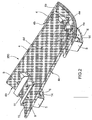
Figure 2 is a perspective view with parts in cross-section and parts removed for clarity of a pair of consecutive and partially overlapping bottom curved tiles of the ventilated roof shown inFigure 1 , reciprocally fixed by means of a support and fixing organ realised according to the present invention; -
Figure 3 is a lateral perspective view of the support and fixing organ shown inFigure 2 ; -
Figure 4 is a lateral perspective view of the support and fixing organ shown inFigure 3 according to a different angle; -
Figure 5 is a raised lateral view of the support and fixing organ shown inFigure 3 ; while -
Figure 6 is a cross-section of the support and fixing organ shown inFigure 5 along line I-I. - With reference to
Figure 1 , thenumber 100 denotes in its entirety a pitch of a ventilated roof of a building (not shown), which comprises a supportingplane 200 having an upper outer surface coplanar to a reference plane A sloped with respect to the vertical side of the building at a predetermined angle, and a roof covering 300 (only partially shown inFigure 1 for reasons of clarity), which is arranged on a lying plane substantially parallel to and spaced from the reference plane A. - Said ventilated
roof 100 also comprises a plurality of support and fixing organs 1, which are arranged lying on the supportingplane 200, and are structured to support and maintain the roof covering 300 on the relative lying plane at a predetermined distance from the upper surface of the supportingplane 200, thus to delimit a ventilation/aeration chamber of theroof 100. Said roof covering 300 comprises a series of parallel alternate rows, concave and convex, of curved tiles, which extend along a transversal direction to the ridge line C of the pitch of the ventilatedroof 100 remaining on the lying plane of said roof covering. - In particular, the rows of curved tiles form a
bottom covering layer 350 of the roof covering, and a top covering layer of the roof covering (not shown), which is over thebottom covering layer 350, so as to form the surface of the visible top covering of the ventilatedroof 100. In the example shown, the curved tiles correspond preferably withtiles 4, each of which is manufactured, for example, in tile, and has a truncated-conical shaped sector and a semi-elliptical transversal cross-section, and is shaped to have a smalleraxial end 4a tapered with respect to an opposing largeraxial end 4b. - The
tiles 4 of each row of the bottom coveringlayer 350 indicated hereunder as bottom curved tiles 4 (since they collect the rainwater and allow it to flow off) are aligned with each other, one after the other, and are arranged so as to have the convex backs 4c turned towards the supportingplane 200 and theconcavities 4d turned upwards, i.e. towards the top covering layer. - In particular, with reference to
Figures 1 and2 , the bottomcurved tiles 4 of each row of the bottom coveringlayer 350 are each arranged so as to have the transversal edge of thelarger end 4b turned towards ridge line C of the roof and the transversal edge of thesmaller end 4b turned in the opposite direction to said ridge line C, for example towards a water collection gutter (not shown) fixed to an outer side edge of the supportingplane 200, parallel to ridge line C. - In greater detail, each bottom curved
tile 4 belonging to a row of tiles has asmaller end 4a at least partially overlapping thelarger end 4b of a bottom curvedtile 4 aligned consecutively so as to form together with the remaining bottom curvedtiles 4 of the same row a substantially straight channel for water off-flow from the roof towards the underlying collection gutter (not shown). - According to a preferred embodiment, the support and fixing organs 1 are structured to maintain the backs of the bottom curved
tiles 4 at a distance from the underlying supportingplane 200 which is greater than the thickness of the bottom curvedtile 4. According to a preferred embodiment, the support and fixing organs 1 are designed to maintain the backs of the bottom curvedtiles 4 at a distance from the underlying supportingplane 200 which is greater than around 3 cm. - With reference to
Figures 1 and2 , the support and fixing organs 1 are arranged lying on the supportingplane 200 beneath the bottomcurved tiles 4 of the bottom coveringlayer 350 and are positioned at the overlappingaxial ends tiles 4. - In particular, with reference to
Figure 2 , each support and fixing organ 1 is designed to grip two separate and reciprocally spacedportions 4e of the transversal edge ofsmaller end 4a of each bottom curvedtile 4, which are arranged on opposite sides of the central plane of said bottom curvedtile 4. - From what is described above, it should be emphasised that gripping the transversal edge of the bottom curved
tile 4 at the twoportions 4e spaced from each other and positioned on opposite sides of the central plane of the bottom curvedtile 4 ensures that the central zone of greater depth of theconcave surface 4d of thecurved tile 4 is completely free of obstacles and therefore allows optimal off-flow of the water inside the channel formed by the row of bottomcurved tiles 4. - According to the invention as shown in
Figures 2-6 the support and fixing organ 1 is preferably, but not necessarily, made of plastic or similar material, obtained for example by means of an injection-moulding process, and comprises arigid socket 5 shaped substantially like a trapezoidal prism or other similar shapes, with alarger base 6 resting on the supportingplane 200, and asmaller base 7, opposite thelarger base 6, on which there is aconcave surface 8 shaped so as to have a complementary shape to the convex back 4c of the bottomcurved tile 4, so as to house thelarger end 4b of it. - According to a possible embodiment, the height of the
socket 5, i.e. the average distance between thelarger base 6 and thesmaller base 7 is greater than around 3 cm. - According to a preferred embodiment shown in
Figures 3-6 , the support and fixing organ 1 also comprises a pair ofrigid tongues 9, which extend in cantilever manner from thesmaller base 7 of thesocket 4 so as to be arranged on opposite sides of the central plane of saidsocket 4 at a predetermined distance from one another, and each have respective end fixing portions designed to grip the transversal edge of thesmaller end 4a at twoportions 4e. - With reference to
Figures 2 ,portions 4e of the transversal edge of thesmaller end 4a of the bottom curvedtile 4 gripped by the fixing portions of therigid tongues 9 are separate and reciprocally spaced and are arranged on opposite sides of the central plane of saidbottom tile 4. - According to a preferred embodiment, said two
rigid tongues 9 are spaced from each other so as to grip, in use, the edge of the bottomcurved tile 4 and also to remain completely beneath the uppercurved tiles 4. In this manner, therigid tongues 9, besides being invisible from the outside and therefore not prejudicing the appearance of the roof, are protected from solar radiation, which would damage them and prejudice fixing. - For this purpose, the distance present between the two
rigid tongues 9 of the organ 1 may be about double the thickness of the larger side edge of a upper curved tile designed to rest on the concave surface of the bottomcurved tile 4 between saidtongues 9. - According to a possible embodiment, the distance between the two
rigid tongues 9 of the organ may conveniently be greater than 3 cm and lower than 10 cm, preferably 3.3 cm. In this manner, each cap/upper curved tile arranged astride of two adjacent bottom curvedtiles 4, i.e. belonging to two rows of adjacent bottom tiles, covers two tongues belonging to two fixing organs 1 adjacent to each other. - According to a preferred embodiment shown in
Figures 5 and 6 , therigid tongues 9 are substantially S-shaped, have a slightly arched transversal section so as to be substantially parallel to the underlyingconcave surface 8 and are arranged on two planes sloped in mirroring positions with respect to the central plane of thesocket 5 at an angle between 65° and 75°, preferably 70°. - With references to
Figures 5-6 , eachrigid tongue 9 comprises aconnection segment 9a, which is fixed to a side edge of thesmaller base 7 at a predetermined distance from the central plane of thesocket 5 and extends vertically from saidsmaller base 7 along a direction substantially orthogonal to theconcave surface 8. - In the example shown in
Figure 5 , eachrigid tongue 9 also comprises a firstintermediate segment 9b, which extends in cantilever manner from the free end of theconnection segment 9a along a direction parallel to theconcave surface 8 and to the central plane of thesocket 5 so as to be arranged above theconcave surface 8 and has a free end which extends beyond said underlyingsmaller base 7. - In particular, the inner surface of the
connection segment 9a and the bottom surface of the firstintermediate segment 9b of each of the tworigid tongues 9 delimit, together with a portion of the area of theconcave surface 8 immediately beneath the firstintermediate segment 9b, a housing orbottom groove 11 sized so as to house and grip a portion of thelarger end 4b of a first bottom curvedtile 4. - In this case, the first
intermediate segment 9b of eachrigid tongue 9 extends above theconcave surface 8 remaining at a distance higher than or equal to the thickness of the bottom curvedtile 4, so as to allow itslarger end 4b to be inserted into/removed from the twobottom grooves 11. - Each
rigid tongue 9 also comprises a secondintermediate segment 9c, which is fixed to the free end of the firstintermediate segment 9b and extends orthogonally to the firstintermediate segment 9b upwards, i.e. in the opposite direction to thesocket 5; and ahooking segment 9d which extends in cantilever manner from the free end of the secondintermediate segment 9c so as to be arranged above the firstintermediate segment 9b and remaining parallel to it and extends towards thesocket 5 so as to extend above one of the twoportions 4e of the transversal edge of thelower end 4a of the bottom curvedtile 4 and thus grip it. - With reference to
Figure 5 , the upper surface of an end portion of the firstintermediate segment 9b, the inner surface of the secondintermediate segment 9c and the lower surface of thehooking segment 9d of eachconnection tongue 9a delimit between them atop groove 12 designed to house and grip one of the twoportions 4e of the transversal edge of thelower end 4a of the second bottom curvedtile 4, so that it is overlapping thelarger end 4b of the first bottomcurved tile 4 gripped in turn in the twobottom grooves 11. - In particular, the hooking
segment 9d, the secondintermediate segment 9c, and the end portion of the firstintermediate segment 9b opposite theconnection segment 9a of the tworigid tongues 9 define the two end connection portions of saidtongues 9 designed to grip the twoportions 4e of the transversal edge of thesmaller end 4a of the second bottom curvedtile 4. - From what is described above, it should be emphasised that the support and
fixing organs 11, due to the presence of thetongues 9, are capable of reciprocally fixing the adjacent bottom curvedtiles 4 of the same row to form an advantageously stable "chain-like" system. - With reference to
Figures 3 and 4 , thesocket 5 is designed to have aeration channels or through-holes 13 which develop parallel to the central plane of thesocket 5, while thelarger base 6 comprises a plate, on which there are a plurality of through-holes 14 designed to allow aeration of the surface of the supportingplane 200 covered by saidlarger base 6. - The supporting surface of the
larger base 6 on the supportingplane 200 is also shaped so as to havelongitudinal teeth 15 which extend parallel to the central plane of the socket 5a thus being arranged alongside the through-holes 14 and which are spaced from each other so as to allow air to pass between the surface of thelarger base 6, the through-holes 14 and the supportingplane 200. - The
longitudinal teeth 15 also have rectangular sections and conveniently define a hooking surface of the support and fixing organ 1 to the supportingplane 200. - In use, the embodiment of a ventilated roof 1 envisages: positioning each support and fixing organ 1 resting on the supporting
plane 200 with the two end fixing portions oriented on the opposite side with respect to ridge line C, so as to insert thelarger end 4b of the first bottom curvedtile 4 inside thebottom grooves 11 of the support organ 1; and to insert thesmaller end 4a of the second bottom curvedtile 4 inside theupper grooves 12 of the support and fixing organ 1, so that the two end fixing portions of the twotongues 9 grip the twoportions 4e of the transversal edge of thesmaller end 4a of the secondcurved tile 4, so as to fix the latter to the first bottom curvedtile 4. - The advantages of the ventilated roof and the support and fixing organ described above are clear.
- The presence of the support socket allows the bottom curved tiles to be spaced from the supporting surface, thus creating the underlying ventilation chamber.
- The tongues of the support organ, due to their position spaced from the central plane, are protected and concealed beneath the overlying roof tile, thereby offering both a visual advantage, since they are not visible from the outside, and a technical advantage, since they are not exposed to solar rays and consequently are not subject to the deterioration caused by them, particularly if they are made of plastic. Furthermore, the tongues grasp the bottom curved tile in two separate points and thereby prevent any swinging movement of the bottom curved tile around its longitudinal axis, thus increasing stability of the ventilated roof and therefore advantageously allowing someone to walk on the upper roof covering of the ventilated roof in total safety during maintenance operations.
- The support and fixing organ is also simple to install, does not require any holes in the supporting surface and guarantees ventilation at the installation points as well.
- In conclusion, the support organ guarantees optimal off-flow of water into the straight channel formed by bottom curved tiles. In fact, the arrangement of the two end fixing portions on opposite sides of the central plane of the socket keeps the central concave part of greater depth of the bottom curved tile completely free, allowing the rainwater to flow more easily along the channel, heavily reducing generation of spray outwards.
- In conclusion, it is clear that changes and variants may be made to the ventilated roof and the support organ described above according to the Claims without deviating from the scope of the present invention.
- In particular, according to a different embodiment of the support organ (not shown), the two rigid tongues are replaced by a central tongue with a larger width which extends in cantilever manner from the socket so as to be arranged above the concave surface and thus to form a single bottom groove, and has on the opposite end two separate and curved L-shaped tabs towards the socket which form the two end hooking portions of the support organ.
- In particular, the central tongue is arranged parallel to the smaller base of the socket and has a width substantially equal to the width of the smaller base, while the two tabs are fixed onto the edge of the central tongue, arranged on the opposite side with respect to the socket, so as to by reciprocally spaced and arranged on opposite sides of the central plane of the socket. The tabs are also folded so as to form two upper grooves designed to grip the two separate portions of the smaller end of the tile.
Claims (14)
- A support and fixing organ (1) designed, in use, to be arranged lying on a supporting plane (200) of a ventilated roof (100) and structured to reciprocally fix a pair of bottom curved tiles (4) of the same row of bottom curved tiles and support them so as to maintain the relative convex backs raised from the underlying supporting plane (200) to form a ventilation chamber; a first axial end (4b) of a first bottom curved tile (4) being arranged beneath a second axial end (4a) of a second bottom curved tile (4) aligned with and adjacent to said first bottom curved tile (4);
said support and fixing organ being characterised by comprising:a rigid socket (5) which is substantially shaped like a trapezoidal prism, and comprises a larger lower base (6) designed to lie on said supporting plane (200), and a smaller top base (7) on which there is a concave surface (8) shaped to have a complementary shape to the convex back (4c) of the first bottom curved tile (4), so as to house said first end (4b) of the first bottom curved tile (4) and maintain the convex back (4c) raised from said supporting plane (200) at a predetermined distance from it; anda pair of rigid tongues (9), which extend in cantilever manner above the top base (7) so as to be arranged on opposite sides of the central plane of said socket (5) at a predetermined distance between them, and have respective end fixing portions which are designed to grip corresponding portions (4e) of the transversal edge of the second axial end (4a) of said second bottom curved tile (4). - The support organ according to Claim 1, wherein the free ends of said rigid tongues (9) are folded so as to form grooves (12) structured to internally house said portions (4e) of the transversal edge of said second axial end(4a) of said second bottom curved tile (4).
- The support organ according to Claim 2, wherein each rigid tongue (9) is folded so as to form with the underlying top base (7) a bottom groove (11) designed to house internally a portion of said first axial end (4b) of said first bottom curved tile (4).
- The support organ according to Claim 3, wherein said rigid tongues (9) each comprise a connection segment (9a) fixed to the socket (5) so as to extend along a direction orthogonal to the top base (7), and a first intermediate segment (9b), which extends above the top base (7) remaining substantially parallel to the top base (7) and forms together with the connection segment (9a) and the top base (7) one of said bottom grooves (11).
- The support organ according to Claim 4, wherein each of said rigid tongues (9) also comprises a second intermediate segment (9c), which is fixed on the free end of the first intermediate segment (9b) and extends orthogonally to the first intermediate segment (9b); and a hooking segment (9d) which extends in cantilever manner from the free end of the second intermediate segment (9c) so as to be arranged above the first intermediate segment (9b) remaining parallel thereto and forms together with the second intermediate segment and a portion of the first intermediate segment (9b) one of said end fixing portions.
- The support organ according to any of Claims 1 to 5, wherein the bottom base (6) of the socket (5) is shaped so as to have a plurality of gripping longitudinal teeth designed to fix the socket (5) to the supporting plane (200).
- The support organ according to any of Claims 1 to 6, wherein the bottom base (6) of the socket (5) has a plurality of openings/through-holes (14).
- The support organ according to any of Claims 1 to 7, wherein the rigid tongues (9) are substantially S-shaped and have a slightly arched transversal section substantially parallel to the underlying concave surface (8) of the bottom base (7).
- The support organ according to any of Claims 1 to 8, wherein the rigid tongues (9) are arranged on two planes sloped in mirroring positions with respect to the central plan of the socket (5) so as to form an angle between 65° and 75°.
- The support organ according to any one of the previous Claims, wherein the distance between two rigid tongues (9) is around double the thickness of the larger side edge of a bottom curved tile (4).
- The support organ according to any one of the previous Claims, wherein the socket (5) has a height greater than around 3 cm.
- The support organ according to any one of the previous Claims, wherein the distance between the rigid tongues (9) is between around 3 cm and around 10 cm.
- The support organ according to any one of the previous Claims, manufactured in plastic material by means of an injection-moulding process.
- A ventilated roof (100) comprising a supporting plane (200) coplanar to a reference plane (A), and a covering layer (300), which is arranged on a lying plane substantially parallel to and spaced from the reference plane (A) at a predetermined distance from it and comprises a plurality of rows of bottom curved tiles (4) parallel to and spaced from each other; said ventilated roof (100) being characterised by comprising a plurality of support organs (1) of the bottom curved tiles (4) made according to any one of the previous Claims.
Priority Applications (1)
| Application Number | Priority Date | Filing Date | Title |
|---|---|---|---|
| SI201330192A SI2825708T1 (en) | 2012-03-12 | 2013-03-12 | Support organ designed to support and reciprocally fix bottom bent tiles of a ventilated roof |
Applications Claiming Priority (2)
| Application Number | Priority Date | Filing Date | Title |
|---|---|---|---|
| IT000035A ITTV20120035A1 (en) | 2012-03-12 | 2012-03-12 | ORGAN OF SUPPORT STRUCTURED TO SUPPORT AND MUTCH ANCHORERS IN A VENTILATED ROOF |
| PCT/IB2013/051954 WO2013136267A1 (en) | 2012-03-12 | 2013-03-12 | Support organ designed to support and reciprocally fix bottom bent tiles of a ventilated roof |
Publications (2)
| Publication Number | Publication Date |
|---|---|
| EP2825708A1 EP2825708A1 (en) | 2015-01-21 |
| EP2825708B1 true EP2825708B1 (en) | 2016-03-09 |
Family
ID=46022588
Family Applications (1)
| Application Number | Title | Priority Date | Filing Date |
|---|---|---|---|
| EP13720067.1A Active EP2825708B1 (en) | 2012-03-12 | 2013-03-12 | Support organ designed to support and reciprocally fix bottom bent tiles of a ventilated roof |
Country Status (5)
| Country | Link |
|---|---|
| EP (1) | EP2825708B1 (en) |
| ES (1) | ES2573808T3 (en) |
| IT (1) | ITTV20120035A1 (en) |
| SI (1) | SI2825708T1 (en) |
| WO (1) | WO2013136267A1 (en) |
Family Cites Families (6)
| Publication number | Priority date | Publication date | Assignee | Title |
|---|---|---|---|---|
| US1520751A (en) * | 1922-02-20 | 1924-12-30 | Harry H Honigbaum | Roofing nail |
| US2106948A (en) * | 1937-04-28 | 1938-02-01 | Harrington Lou | No screed tile clip |
| GB8728900D0 (en) * | 1987-12-10 | 1988-01-27 | Smith H | Roof tile/slate retainer |
| DE8815566U1 (en) * | 1988-12-15 | 1989-01-26 | Fleck, Oskar, 4354 Datteln | Ridge tile bracket |
| IT1314712B1 (en) * | 1998-02-23 | 2002-12-31 | Vincenzo Santagata | METHOD FOR FIXING BETWEEN THEIR TILES AND SIMILAR FOR THE COVERING OF A ROOF AND ANCHORING ELEMENT TO IMPLEMENT THIS METHOD. |
| ITPI20060050A1 (en) * | 2006-04-24 | 2007-10-25 | Vincenzo Santagata | DEVICE FOR ANCHORING TILES AND ROOF PANES. |
-
2012
- 2012-03-12 IT IT000035A patent/ITTV20120035A1/en unknown
-
2013
- 2013-03-12 SI SI201330192A patent/SI2825708T1/en unknown
- 2013-03-12 ES ES13720067.1T patent/ES2573808T3/en active Active
- 2013-03-12 EP EP13720067.1A patent/EP2825708B1/en active Active
- 2013-03-12 WO PCT/IB2013/051954 patent/WO2013136267A1/en not_active Ceased
Also Published As
| Publication number | Publication date |
|---|---|
| WO2013136267A1 (en) | 2013-09-19 |
| ES2573808T3 (en) | 2016-06-10 |
| EP2825708A1 (en) | 2015-01-21 |
| ITTV20120035A1 (en) | 2013-09-13 |
| SI2825708T1 (en) | 2016-07-29 |
Similar Documents
| Publication | Publication Date | Title |
|---|---|---|
| US6941706B2 (en) | Vented eaves closure | |
| CA2755006C (en) | Hidden ridge vent for slate roofs | |
| US20190024378A1 (en) | Contoured Mesh Ridge Vents | |
| US9410323B1 (en) | Roofing shingle system and shingles for use therein | |
| US4800675A (en) | Roofing plate for planting greenery on roofs | |
| CA2989813C (en) | Ridge vent | |
| CA2496496A1 (en) | Vented soffit panel and method for buildings and the like | |
| US20040144040A1 (en) | Weather block for low or high profile tile | |
| EP0340856B1 (en) | Roof ventilation | |
| WO2013136267A1 (en) | Support organ designed to support and reciprocally fix bottom bent tiles of a ventilated roof | |
| US8316601B2 (en) | Under deck drainage system | |
| WO2011121370A2 (en) | Self-ventilated pergola | |
| CA2837807C (en) | Contoured mesh ridge vents | |
| CA2762801A1 (en) | Soffit venting system | |
| EP2880225B1 (en) | Ventilated roof and method for manufacturing a ventilated roof | |
| WO2013054151A1 (en) | Rooftop covering structure for self-ventilated roofs | |
| JP5313086B2 (en) | Staggered thatched flat tile | |
| EP2045411A2 (en) | Tile, particularly for providing roofings | |
| JP5411801B2 (en) | Tile roofs and base piers for ridges on tile roofs | |
| JP4087980B2 (en) | Flooring material laying structure | |
| JP3151736U (en) | Roof structure | |
| JP2007247398A (en) | Tile roof structure | |
| EP2989266B1 (en) | Tile, tile assembly and facade or roof covering | |
| GB2312689A (en) | Roof tiles | |
| KR100959354B1 (en) | Ridge floor flashing |
Legal Events
| Date | Code | Title | Description |
|---|---|---|---|
| PUAI | Public reference made under article 153(3) epc to a published international application that has entered the european phase |
Free format text: ORIGINAL CODE: 0009012 |
|
| 17P | Request for examination filed |
Effective date: 20140924 |
|
| AK | Designated contracting states |
Kind code of ref document: A1 Designated state(s): AL AT BE BG CH CY CZ DE DK EE ES FI FR GB GR HR HU IE IS IT LI LT LU LV MC MK MT NL NO PL PT RO RS SE SI SK SM TR |
|
| AX | Request for extension of the european patent |
Extension state: BA ME |
|
| DAX | Request for extension of the european patent (deleted) | ||
| GRAP | Despatch of communication of intention to grant a patent |
Free format text: ORIGINAL CODE: EPIDOSNIGR1 |
|
| INTG | Intention to grant announced |
Effective date: 20150915 |
|
| GRAS | Grant fee paid |
Free format text: ORIGINAL CODE: EPIDOSNIGR3 |
|
| GRAA | (expected) grant |
Free format text: ORIGINAL CODE: 0009210 |
|
| AK | Designated contracting states |
Kind code of ref document: B1 Designated state(s): AL AT BE BG CH CY CZ DE DK EE ES FI FR GB GR HR HU IE IS IT LI LT LU LV MC MK MT NL NO PL PT RO RS SE SI SK SM TR |
|
| REG | Reference to a national code |
Ref country code: GB Ref legal event code: FG4D |
|
| REG | Reference to a national code |
Ref country code: AT Ref legal event code: REF Ref document number: 779666 Country of ref document: AT Kind code of ref document: T Effective date: 20160315 Ref country code: CH Ref legal event code: EP |
|
| REG | Reference to a national code |
Ref country code: IE Ref legal event code: FG4D |
|
| REG | Reference to a national code |
Ref country code: DE Ref legal event code: R096 Ref document number: 602013005411 Country of ref document: DE |
|
| REG | Reference to a national code |
Ref country code: FR Ref legal event code: PLFP Year of fee payment: 4 |
|
| REG | Reference to a national code |
Ref country code: ES Ref legal event code: FG2A Ref document number: 2573808 Country of ref document: ES Kind code of ref document: T3 Effective date: 20160610 |
|
| REG | Reference to a national code |
Ref country code: CH Ref legal event code: NV Representative=s name: ANDRE ROLAND S.A., CH |
|
| REG | Reference to a national code |
Ref country code: LT Ref legal event code: MG4D |
|
| REG | Reference to a national code |
Ref country code: NL Ref legal event code: MP Effective date: 20160309 |
|
| PG25 | Lapsed in a contracting state [announced via postgrant information from national office to epo] |
Ref country code: NO Free format text: LAPSE BECAUSE OF FAILURE TO SUBMIT A TRANSLATION OF THE DESCRIPTION OR TO PAY THE FEE WITHIN THE PRESCRIBED TIME-LIMIT Effective date: 20160609 Ref country code: FI Free format text: LAPSE BECAUSE OF FAILURE TO SUBMIT A TRANSLATION OF THE DESCRIPTION OR TO PAY THE FEE WITHIN THE PRESCRIBED TIME-LIMIT Effective date: 20160309 Ref country code: HR Free format text: LAPSE BECAUSE OF FAILURE TO SUBMIT A TRANSLATION OF THE DESCRIPTION OR TO PAY THE FEE WITHIN THE PRESCRIBED TIME-LIMIT Effective date: 20160309 Ref country code: GR Free format text: LAPSE BECAUSE OF FAILURE TO SUBMIT A TRANSLATION OF THE DESCRIPTION OR TO PAY THE FEE WITHIN THE PRESCRIBED TIME-LIMIT Effective date: 20160610 |
|
| REG | Reference to a national code |
Ref country code: AT Ref legal event code: MK05 Ref document number: 779666 Country of ref document: AT Kind code of ref document: T Effective date: 20160309 |
|
| PG25 | Lapsed in a contracting state [announced via postgrant information from national office to epo] |
Ref country code: LV Free format text: LAPSE BECAUSE OF FAILURE TO SUBMIT A TRANSLATION OF THE DESCRIPTION OR TO PAY THE FEE WITHIN THE PRESCRIBED TIME-LIMIT Effective date: 20160309 Ref country code: NL Free format text: LAPSE BECAUSE OF FAILURE TO SUBMIT A TRANSLATION OF THE DESCRIPTION OR TO PAY THE FEE WITHIN THE PRESCRIBED TIME-LIMIT Effective date: 20160309 Ref country code: LT Free format text: LAPSE BECAUSE OF FAILURE TO SUBMIT A TRANSLATION OF THE DESCRIPTION OR TO PAY THE FEE WITHIN THE PRESCRIBED TIME-LIMIT Effective date: 20160309 Ref country code: RS Free format text: LAPSE BECAUSE OF FAILURE TO SUBMIT A TRANSLATION OF THE DESCRIPTION OR TO PAY THE FEE WITHIN THE PRESCRIBED TIME-LIMIT Effective date: 20160309 Ref country code: SE Free format text: LAPSE BECAUSE OF FAILURE TO SUBMIT A TRANSLATION OF THE DESCRIPTION OR TO PAY THE FEE WITHIN THE PRESCRIBED TIME-LIMIT Effective date: 20160309 Ref country code: BE Free format text: LAPSE BECAUSE OF NON-PAYMENT OF DUE FEES Effective date: 20160331 Ref country code: PL Free format text: LAPSE BECAUSE OF FAILURE TO SUBMIT A TRANSLATION OF THE DESCRIPTION OR TO PAY THE FEE WITHIN THE PRESCRIBED TIME-LIMIT Effective date: 20160309 |
|
| REG | Reference to a national code |
Ref country code: DE Ref legal event code: R119 Ref document number: 602013005411 Country of ref document: DE |
|
| PG25 | Lapsed in a contracting state [announced via postgrant information from national office to epo] |
Ref country code: IS Free format text: LAPSE BECAUSE OF FAILURE TO SUBMIT A TRANSLATION OF THE DESCRIPTION OR TO PAY THE FEE WITHIN THE PRESCRIBED TIME-LIMIT Effective date: 20160709 Ref country code: EE Free format text: LAPSE BECAUSE OF FAILURE TO SUBMIT A TRANSLATION OF THE DESCRIPTION OR TO PAY THE FEE WITHIN THE PRESCRIBED TIME-LIMIT Effective date: 20160309 |
|
| PG25 | Lapsed in a contracting state [announced via postgrant information from national office to epo] |
Ref country code: SK Free format text: LAPSE BECAUSE OF FAILURE TO SUBMIT A TRANSLATION OF THE DESCRIPTION OR TO PAY THE FEE WITHIN THE PRESCRIBED TIME-LIMIT Effective date: 20160309 Ref country code: RO Free format text: LAPSE BECAUSE OF FAILURE TO SUBMIT A TRANSLATION OF THE DESCRIPTION OR TO PAY THE FEE WITHIN THE PRESCRIBED TIME-LIMIT Effective date: 20160309 Ref country code: SM Free format text: LAPSE BECAUSE OF FAILURE TO SUBMIT A TRANSLATION OF THE DESCRIPTION OR TO PAY THE FEE WITHIN THE PRESCRIBED TIME-LIMIT Effective date: 20160309 Ref country code: PT Free format text: LAPSE BECAUSE OF FAILURE TO SUBMIT A TRANSLATION OF THE DESCRIPTION OR TO PAY THE FEE WITHIN THE PRESCRIBED TIME-LIMIT Effective date: 20160711 Ref country code: CZ Free format text: LAPSE BECAUSE OF FAILURE TO SUBMIT A TRANSLATION OF THE DESCRIPTION OR TO PAY THE FEE WITHIN THE PRESCRIBED TIME-LIMIT Effective date: 20160309 Ref country code: AT Free format text: LAPSE BECAUSE OF FAILURE TO SUBMIT A TRANSLATION OF THE DESCRIPTION OR TO PAY THE FEE WITHIN THE PRESCRIBED TIME-LIMIT Effective date: 20160309 |
|
| REG | Reference to a national code |
Ref country code: IE Ref legal event code: MM4A |
|
| PG25 | Lapsed in a contracting state [announced via postgrant information from national office to epo] |
Ref country code: BE Free format text: LAPSE BECAUSE OF FAILURE TO SUBMIT A TRANSLATION OF THE DESCRIPTION OR TO PAY THE FEE WITHIN THE PRESCRIBED TIME-LIMIT Effective date: 20160309 Ref country code: IT Free format text: LAPSE BECAUSE OF FAILURE TO SUBMIT A TRANSLATION OF THE DESCRIPTION OR TO PAY THE FEE WITHIN THE PRESCRIBED TIME-LIMIT Effective date: 20160309 |
|
| PLBE | No opposition filed within time limit |
Free format text: ORIGINAL CODE: 0009261 |
|
| STAA | Information on the status of an ep patent application or granted ep patent |
Free format text: STATUS: NO OPPOSITION FILED WITHIN TIME LIMIT |
|
| PG25 | Lapsed in a contracting state [announced via postgrant information from national office to epo] |
Ref country code: IE Free format text: LAPSE BECAUSE OF NON-PAYMENT OF DUE FEES Effective date: 20160312 Ref country code: DE Free format text: LAPSE BECAUSE OF NON-PAYMENT OF DUE FEES Effective date: 20161001 Ref country code: DK Free format text: LAPSE BECAUSE OF FAILURE TO SUBMIT A TRANSLATION OF THE DESCRIPTION OR TO PAY THE FEE WITHIN THE PRESCRIBED TIME-LIMIT Effective date: 20160309 |
|
| 26N | No opposition filed |
Effective date: 20161212 |
|
| PG25 | Lapsed in a contracting state [announced via postgrant information from national office to epo] |
Ref country code: BG Free format text: LAPSE BECAUSE OF FAILURE TO SUBMIT A TRANSLATION OF THE DESCRIPTION OR TO PAY THE FEE WITHIN THE PRESCRIBED TIME-LIMIT Effective date: 20160609 |
|
| REG | Reference to a national code |
Ref country code: FR Ref legal event code: PLFP Year of fee payment: 5 |
|
| PG25 | Lapsed in a contracting state [announced via postgrant information from national office to epo] |
Ref country code: MT Free format text: LAPSE BECAUSE OF FAILURE TO SUBMIT A TRANSLATION OF THE DESCRIPTION OR TO PAY THE FEE WITHIN THE PRESCRIBED TIME-LIMIT Effective date: 20160309 |
|
| GBPC | Gb: european patent ceased through non-payment of renewal fee |
Effective date: 20170312 |
|
| PG25 | Lapsed in a contracting state [announced via postgrant information from national office to epo] |
Ref country code: GB Free format text: LAPSE BECAUSE OF NON-PAYMENT OF DUE FEES Effective date: 20170312 |
|
| REG | Reference to a national code |
Ref country code: FR Ref legal event code: PLFP Year of fee payment: 6 |
|
| PG25 | Lapsed in a contracting state [announced via postgrant information from national office to epo] |
Ref country code: HU Free format text: LAPSE BECAUSE OF FAILURE TO SUBMIT A TRANSLATION OF THE DESCRIPTION OR TO PAY THE FEE WITHIN THE PRESCRIBED TIME-LIMIT; INVALID AB INITIO Effective date: 20130312 |
|
| PG25 | Lapsed in a contracting state [announced via postgrant information from national office to epo] |
Ref country code: MC Free format text: LAPSE BECAUSE OF FAILURE TO SUBMIT A TRANSLATION OF THE DESCRIPTION OR TO PAY THE FEE WITHIN THE PRESCRIBED TIME-LIMIT Effective date: 20160309 Ref country code: MK Free format text: LAPSE BECAUSE OF FAILURE TO SUBMIT A TRANSLATION OF THE DESCRIPTION OR TO PAY THE FEE WITHIN THE PRESCRIBED TIME-LIMIT Effective date: 20160309 Ref country code: CY Free format text: LAPSE BECAUSE OF FAILURE TO SUBMIT A TRANSLATION OF THE DESCRIPTION OR TO PAY THE FEE WITHIN THE PRESCRIBED TIME-LIMIT Effective date: 20160309 Ref country code: MT Free format text: LAPSE BECAUSE OF FAILURE TO SUBMIT A TRANSLATION OF THE DESCRIPTION OR TO PAY THE FEE WITHIN THE PRESCRIBED TIME-LIMIT Effective date: 20160331 Ref country code: LU Free format text: LAPSE BECAUSE OF NON-PAYMENT OF DUE FEES Effective date: 20160312 |
|
| PG25 | Lapsed in a contracting state [announced via postgrant information from national office to epo] |
Ref country code: TR Free format text: LAPSE BECAUSE OF FAILURE TO SUBMIT A TRANSLATION OF THE DESCRIPTION OR TO PAY THE FEE WITHIN THE PRESCRIBED TIME-LIMIT Effective date: 20160309 Ref country code: AL Free format text: LAPSE BECAUSE OF FAILURE TO SUBMIT A TRANSLATION OF THE DESCRIPTION OR TO PAY THE FEE WITHIN THE PRESCRIBED TIME-LIMIT Effective date: 20160309 |
|
| PGFP | Annual fee paid to national office [announced via postgrant information from national office to epo] |
Ref country code: CH Payment date: 20200324 Year of fee payment: 8 |
|
| REG | Reference to a national code |
Ref country code: CH Ref legal event code: PL |
|
| PG25 | Lapsed in a contracting state [announced via postgrant information from national office to epo] |
Ref country code: CH Free format text: LAPSE BECAUSE OF NON-PAYMENT OF DUE FEES Effective date: 20210331 Ref country code: LI Free format text: LAPSE BECAUSE OF NON-PAYMENT OF DUE FEES Effective date: 20210331 |
|
| PGFP | Annual fee paid to national office [announced via postgrant information from national office to epo] |
Ref country code: ES Payment date: 20250423 Year of fee payment: 13 |
|
| PGFP | Annual fee paid to national office [announced via postgrant information from national office to epo] |
Ref country code: FR Payment date: 20260323 Year of fee payment: 14 |
|
| PGFP | Annual fee paid to national office [announced via postgrant information from national office to epo] |
Ref country code: SI Payment date: 20260219 Year of fee payment: 14 |