EP2825367B1 - VIBRATIONSSCHWEIßMASCHINE UND VERFAHREN ZUM BETREIBEN EINER VIBRATIONSSCHWEISSMASCHINE - Google Patents
VIBRATIONSSCHWEIßMASCHINE UND VERFAHREN ZUM BETREIBEN EINER VIBRATIONSSCHWEISSMASCHINE Download PDFInfo
- Publication number
- EP2825367B1 EP2825367B1 EP13710397.4A EP13710397A EP2825367B1 EP 2825367 B1 EP2825367 B1 EP 2825367B1 EP 13710397 A EP13710397 A EP 13710397A EP 2825367 B1 EP2825367 B1 EP 2825367B1
- Authority
- EP
- European Patent Office
- Prior art keywords
- vibration
- air gap
- air
- oscillator
- vibration welding
- Prior art date
- Legal status (The legal status is an assumption and is not a legal conclusion. Google has not performed a legal analysis and makes no representation as to the accuracy of the status listed.)
- Not-in-force
Links
- 238000003466 welding Methods 0.000 title claims description 53
- 238000000034 method Methods 0.000 title claims description 21
- 230000010355 oscillation Effects 0.000 claims 2
- 238000005304 joining Methods 0.000 description 7
- 238000004519 manufacturing process Methods 0.000 description 6
- 230000005284 excitation Effects 0.000 description 3
- 238000009413 insulation Methods 0.000 description 3
- 230000003534 oscillatory effect Effects 0.000 description 2
- 238000007789 sealing Methods 0.000 description 2
- 230000002411 adverse Effects 0.000 description 1
- 230000006835 compression Effects 0.000 description 1
- 238000007906 compression Methods 0.000 description 1
- 230000000694 effects Effects 0.000 description 1
- 238000000605 extraction Methods 0.000 description 1
- 239000007769 metal material Substances 0.000 description 1
- 238000003860 storage Methods 0.000 description 1
Images
Classifications
-
- B—PERFORMING OPERATIONS; TRANSPORTING
- B32—LAYERED PRODUCTS
- B32B—LAYERED PRODUCTS, i.e. PRODUCTS BUILT-UP OF STRATA OF FLAT OR NON-FLAT, e.g. CELLULAR OR HONEYCOMB, FORM
- B32B37/00—Methods or apparatus for laminating, e.g. by curing or by ultrasonic bonding
- B32B37/0007—Methods or apparatus for laminating, e.g. by curing or by ultrasonic bonding involving treatment or provisions in order to avoid deformation or air inclusion, e.g. to improve surface quality
- B32B37/003—Methods or apparatus for laminating, e.g. by curing or by ultrasonic bonding involving treatment or provisions in order to avoid deformation or air inclusion, e.g. to improve surface quality to avoid air inclusion
-
- B—PERFORMING OPERATIONS; TRANSPORTING
- B29—WORKING OF PLASTICS; WORKING OF SUBSTANCES IN A PLASTIC STATE IN GENERAL
- B29C—SHAPING OR JOINING OF PLASTICS; SHAPING OF MATERIAL IN A PLASTIC STATE, NOT OTHERWISE PROVIDED FOR; AFTER-TREATMENT OF THE SHAPED PRODUCTS, e.g. REPAIRING
- B29C65/00—Joining or sealing of preformed parts, e.g. welding of plastics materials; Apparatus therefor
- B29C65/02—Joining or sealing of preformed parts, e.g. welding of plastics materials; Apparatus therefor by heating, with or without pressure
- B29C65/06—Joining or sealing of preformed parts, e.g. welding of plastics materials; Apparatus therefor by heating, with or without pressure using friction, e.g. spin welding
- B29C65/0609—Joining or sealing of preformed parts, e.g. welding of plastics materials; Apparatus therefor by heating, with or without pressure using friction, e.g. spin welding characterised by the movement of the parts to be joined
- B29C65/0618—Linear
-
- B—PERFORMING OPERATIONS; TRANSPORTING
- B29—WORKING OF PLASTICS; WORKING OF SUBSTANCES IN A PLASTIC STATE IN GENERAL
- B29C—SHAPING OR JOINING OF PLASTICS; SHAPING OF MATERIAL IN A PLASTIC STATE, NOT OTHERWISE PROVIDED FOR; AFTER-TREATMENT OF THE SHAPED PRODUCTS, e.g. REPAIRING
- B29C66/00—General aspects of processes or apparatus for joining preformed parts
- B29C66/80—General aspects of machine operations or constructions and parts thereof
- B29C66/82—Pressure application arrangements, e.g. transmission or actuating mechanisms for joining tools or clamps
- B29C66/824—Actuating mechanisms
- B29C66/8242—Pneumatic or hydraulic drives
-
- B—PERFORMING OPERATIONS; TRANSPORTING
- B29—WORKING OF PLASTICS; WORKING OF SUBSTANCES IN A PLASTIC STATE IN GENERAL
- B29C—SHAPING OR JOINING OF PLASTICS; SHAPING OF MATERIAL IN A PLASTIC STATE, NOT OTHERWISE PROVIDED FOR; AFTER-TREATMENT OF THE SHAPED PRODUCTS, e.g. REPAIRING
- B29C66/00—General aspects of processes or apparatus for joining preformed parts
- B29C66/80—General aspects of machine operations or constructions and parts thereof
- B29C66/82—Pressure application arrangements, e.g. transmission or actuating mechanisms for joining tools or clamps
- B29C66/824—Actuating mechanisms
- B29C66/8244—Actuating mechanisms magnetically driven
-
- B—PERFORMING OPERATIONS; TRANSPORTING
- B29—WORKING OF PLASTICS; WORKING OF SUBSTANCES IN A PLASTIC STATE IN GENERAL
- B29C—SHAPING OR JOINING OF PLASTICS; SHAPING OF MATERIAL IN A PLASTIC STATE, NOT OTHERWISE PROVIDED FOR; AFTER-TREATMENT OF THE SHAPED PRODUCTS, e.g. REPAIRING
- B29C66/00—General aspects of processes or apparatus for joining preformed parts
- B29C66/80—General aspects of machine operations or constructions and parts thereof
- B29C66/83—General aspects of machine operations or constructions and parts thereof characterised by the movement of the joining or pressing tools
- B29C66/832—Reciprocating joining or pressing tools
- B29C66/8322—Joining or pressing tools reciprocating along one axis
-
- B—PERFORMING OPERATIONS; TRANSPORTING
- B32—LAYERED PRODUCTS
- B32B—LAYERED PRODUCTS, i.e. PRODUCTS BUILT-UP OF STRATA OF FLAT OR NON-FLAT, e.g. CELLULAR OR HONEYCOMB, FORM
- B32B37/00—Methods or apparatus for laminating, e.g. by curing or by ultrasonic bonding
- B32B37/04—Methods or apparatus for laminating, e.g. by curing or by ultrasonic bonding characterised by the partial melting of at least one layer
-
- B—PERFORMING OPERATIONS; TRANSPORTING
- B29—WORKING OF PLASTICS; WORKING OF SUBSTANCES IN A PLASTIC STATE IN GENERAL
- B29C—SHAPING OR JOINING OF PLASTICS; SHAPING OF MATERIAL IN A PLASTIC STATE, NOT OTHERWISE PROVIDED FOR; AFTER-TREATMENT OF THE SHAPED PRODUCTS, e.g. REPAIRING
- B29C65/00—Joining or sealing of preformed parts, e.g. welding of plastics materials; Apparatus therefor
- B29C65/78—Means for handling the parts to be joined, e.g. for making containers or hollow articles, e.g. means for handling sheets, plates, web-like materials, tubular articles, hollow articles or elements to be joined therewith; Means for discharging the joined articles from the joining apparatus
- B29C65/7841—Holding or clamping means for handling purposes
-
- B—PERFORMING OPERATIONS; TRANSPORTING
- B29—WORKING OF PLASTICS; WORKING OF SUBSTANCES IN A PLASTIC STATE IN GENERAL
- B29C—SHAPING OR JOINING OF PLASTICS; SHAPING OF MATERIAL IN A PLASTIC STATE, NOT OTHERWISE PROVIDED FOR; AFTER-TREATMENT OF THE SHAPED PRODUCTS, e.g. REPAIRING
- B29C66/00—General aspects of processes or apparatus for joining preformed parts
- B29C66/80—General aspects of machine operations or constructions and parts thereof
- B29C66/87—Auxiliary operations or devices
- B29C66/874—Safety measures or devices
- B29C66/8742—Safety measures or devices for operators
-
- B—PERFORMING OPERATIONS; TRANSPORTING
- B29—WORKING OF PLASTICS; WORKING OF SUBSTANCES IN A PLASTIC STATE IN GENERAL
- B29C—SHAPING OR JOINING OF PLASTICS; SHAPING OF MATERIAL IN A PLASTIC STATE, NOT OTHERWISE PROVIDED FOR; AFTER-TREATMENT OF THE SHAPED PRODUCTS, e.g. REPAIRING
- B29C66/00—General aspects of processes or apparatus for joining preformed parts
- B29C66/90—Measuring or controlling the joining process
- B29C66/95—Measuring or controlling the joining process by measuring or controlling specific variables not covered by groups B29C66/91 - B29C66/94
- B29C66/951—Measuring or controlling the joining process by measuring or controlling specific variables not covered by groups B29C66/91 - B29C66/94 by measuring or controlling the vibration frequency and/or the vibration amplitude of vibrating joining tools, e.g. of ultrasonic welding tools
- B29C66/9513—Measuring or controlling the joining process by measuring or controlling specific variables not covered by groups B29C66/91 - B29C66/94 by measuring or controlling the vibration frequency and/or the vibration amplitude of vibrating joining tools, e.g. of ultrasonic welding tools characterised by specific vibration frequency values or ranges
-
- B—PERFORMING OPERATIONS; TRANSPORTING
- B29—WORKING OF PLASTICS; WORKING OF SUBSTANCES IN A PLASTIC STATE IN GENERAL
- B29C—SHAPING OR JOINING OF PLASTICS; SHAPING OF MATERIAL IN A PLASTIC STATE, NOT OTHERWISE PROVIDED FOR; AFTER-TREATMENT OF THE SHAPED PRODUCTS, e.g. REPAIRING
- B29C66/00—General aspects of processes or apparatus for joining preformed parts
- B29C66/90—Measuring or controlling the joining process
- B29C66/95—Measuring or controlling the joining process by measuring or controlling specific variables not covered by groups B29C66/91 - B29C66/94
- B29C66/951—Measuring or controlling the joining process by measuring or controlling specific variables not covered by groups B29C66/91 - B29C66/94 by measuring or controlling the vibration frequency and/or the vibration amplitude of vibrating joining tools, e.g. of ultrasonic welding tools
- B29C66/9517—Measuring or controlling the joining process by measuring or controlling specific variables not covered by groups B29C66/91 - B29C66/94 by measuring or controlling the vibration frequency and/or the vibration amplitude of vibrating joining tools, e.g. of ultrasonic welding tools characterised by specific vibration amplitude values or ranges
-
- B—PERFORMING OPERATIONS; TRANSPORTING
- B32—LAYERED PRODUCTS
- B32B—LAYERED PRODUCTS, i.e. PRODUCTS BUILT-UP OF STRATA OF FLAT OR NON-FLAT, e.g. CELLULAR OR HONEYCOMB, FORM
- B32B38/00—Ancillary operations in connection with laminating processes
- B32B2038/0052—Other operations not otherwise provided for
-
- B—PERFORMING OPERATIONS; TRANSPORTING
- B32—LAYERED PRODUCTS
- B32B—LAYERED PRODUCTS, i.e. PRODUCTS BUILT-UP OF STRATA OF FLAT OR NON-FLAT, e.g. CELLULAR OR HONEYCOMB, FORM
- B32B2309/00—Parameters for the laminating or treatment process; Apparatus details
- B32B2309/12—Pressure
-
- B—PERFORMING OPERATIONS; TRANSPORTING
- B32—LAYERED PRODUCTS
- B32B—LAYERED PRODUCTS, i.e. PRODUCTS BUILT-UP OF STRATA OF FLAT OR NON-FLAT, e.g. CELLULAR OR HONEYCOMB, FORM
- B32B2309/00—Parameters for the laminating or treatment process; Apparatus details
- B32B2309/60—In a particular environment
- B32B2309/68—Vacuum
Definitions
- the invention relates to a vibration welding machine and a method for operating such a vibration welding machine according to the features of the respective preambles of the independent claims.
- vibration welding machines and methods for operating such vibration welding machines which have an upper tool and a lower tool, each one of the two tools each receiving a welded part, wherein the two welding parts in the region of a joining zone by means of vibration welding permanently and permanently connected to each other.
- the welded parts are made of plastic and, if necessary, can also be heated in addition to being put into vibration in order to improve the joining process.
- one of the tools for example the lower tool
- the other tool for example the upper tool
- vibrated so that the joining zones of the two tools rub against each other, thereby generating heat and thereby permanently joined together in the region of this joining zone, if the Vibration welding process is completed.
- the structure of such vibration welding machines is basically known, and these are processed in the series production of components which consist of at least two welded parts.
- such vibration welding machines are used for the mass production of components in large numbers, often also several vibration welding machines are in a production hall.
- the invention is therefore based on the object to improve a vibration welding machine and a method for operating such a vibration welding machine to the effect that especially during the vibration welding process, the resulting noise can be significantly reduced without much effort.
- the vibration generating means are formed as a fixed upper carrier and a vibrator arranged to oscillate thereon, which accommodates the upper tool, wherein means are further provided which correspond to the air gap formed between the upper carrier and the oscillator remove air. It has been found that in vibration welding machines fixed and swinging parts exist, wherein the swinging movable part is relatively oscillated with respect to the fixed part. In order to enable such oscillating movement, it is necessary to provide an air gap between the fixed part and the oscillating part.
- the invention proposes that means are provided which remove the air located in an air gap between these two parts.
- the term "remove” is understood to mean that air is in the air gap, which is sucked off, for example. It should also be understood that measures are taken which prevent the air gap from generating any appreciable volume of air which could be excited by vibrations.
- the area of the air gap is sealed to the outside environment, so that although an air volume is in the air gap, but due to the seal either is not excited to vibrate or, if so, by the seal the resulting noise generation effectively is dampened.
- the noise level at the location where they occur either significantly reduce or prevent at best completely by the measures described above, so that thus the sound level of the entire vibration welding machine is significantly reduced in their work, without much effort to operate.
- the means by which the air in the air gap is removed are formed as a seal around the air gap. This means that an air volume is formed in the air gap of the fixed part and of the oscillating part and exactly this area, which forms the air gap of the two parts, is sealed from the outside environment. It follows that, although there is an air volume between the two parts and is excited as a result of the movement of the oscillating member also to vibrate through the seal these sounds advantageously not escape to the outside.
- the means for removing the air located between the air gap are formed as a housing around the air gap around.
- the oscillating member including the fixed part therearound may be surrounded by a housing, while the air in the air gap is excited due to the swinging motion of the movable member, but at the same time the resulting sound can not be delivered to the outside environment.
- a housing can be much smaller than a complete enclosure of the vibration machine, so that advantageously the noise level can be reduced with simple measures.
- the housing can be made very simple, with only a swinging, elastic or the like formed seal between the fixed housing and the oscillating part must be made. In addition, this housing does not hinder the serial production, since only substantially the oscillatory part is surrounded by the housing, whereas its tool, to which the one welding part is attached, is freely accessible.
- the means are designed as negative pressure generating means, with which the air located at least in the air gap is sucked off.
- a negative pressure which is generated by corresponding means (such as a vacuum pump or the like)
- either the air volume, which is located in the air gap between the oscillating and the stationary part can be selectively aspirated.
- the air which is located in the air gap between the oscillating and stationary parts to be removed by suitable method steps and, if appropriate, also for the air located around it.
- a higher cycle time is possible in particular in the series production of weld parts to be joined, since it is no longer necessary to remove the complete housing for the purpose of changing the welding parts and then reinstalling them.
- the welding part change (and possibly also a tool change) can be done at any time, without the entire enclosure must be removed for the purpose of sound insulation, because according to the invention advantageously that air volume is selectively removed at the point where it is present and would provide a negative noise level ,
- the principle according to the invention is based on a fast linear deflection of a welding head (oscillator) in relation to a rigid table (top carrier or lifting table).
- the frequency is, for example, about 70 to 260 hertz, preferably 180 to 240 hertz, more preferably 200 to 240 hertz.
- the amplitude is up to 2 mm (amplitude up to 4 mm), preferably 1.5 mm (amplitude up to 3 mm), more preferably 1 mm (swing width 2 mm).
- the frequency is from 80 to 130 hertz, preferably 100 to 120 hertz, the amplitude to 2 mm, maximum to 2.5 mm.
- the oscillating head is a resonant oscillator with a magnetic spring oscillating system. Strong magnets divert the head.
- the spring provides for the provision.
- the solution is the principle of an evacuated gap on the oscillating head to avoid the generation of sound or to reduce the noise emission.
- the volume of the gap may be reduced by increasing the volume in the region surrounding the gap for further noise reduction in order to reduce the compression rate.
- the magnification are, for example, holes, pockets and the like.
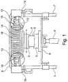
- FIG. 1 is a schematic representation of a vibration welding machine drawn, which includes at least one upper tool 2 as a vibrating part and at least one lower tool 3 as a fixed part.
- two welding parts 4, 5 are held (clamped there or the like) in order to move towards each other and to vibrate.
- frictional heat is generated in the region of the corresponding joining zones of the two welding parts 4, 5, so that they are joined together there and remain permanently connected when they are removed again from the two tools 2, 3.
- Prefabricated components are preferably used and joined together as welded parts 4, 5 of corresponding plastic, wherein it is not excluded that other parts which can be joined together by means of a vibration welding operation are used from corresponding components.
- welding parts made of a metallic material can also be used (friction welding process).
- the vibration welding machine 1 further comprises a lifting table 6, which is linearly movable, for example, on guide columns 7.
- a table drive 8 for example an electric drive, a hydraulic drive or the like.
- the table drive 8 moves the lifting table 6 upwards in the direction of the upper tool 2 facing it, with the welding part 4 clamped therein, so that the facing joining zones of the two welding parts 4, 5 come into abutment.
- This linear movement of the lifting table 6 can optionally be tracked during the vibration welding process (as described below).
- the oscillating part of the vibratory machine 1 comprises an upper carrier 9, which is arranged in this case via a bearing 10, possibly an elastic bearing, on the guide columns 7.
- the upper support 9 at a different location of the vibration welding machine 1 (not shown here) to arrange.
- Important for the vibration welding process is a fixed arrangement of the fixed part, here of the upper support 9.
- a vibrating part here a vibrator 11, arranged on the oscillator 11, the upper tool 2 for receiving the a welding part 4 is arranged.
- the oscillating part, here the oscillator 11, is in principle set in a swinging motion, for which corresponding drive means are present.
- these means for vibration generation are designed as resonance oscillators with a magnetic spring-oscillation system.
- a spring assembly 14 is present in support of the vibration welding process in the vibrator 11.
- the oscillator 11 or generally a vibrating part, also called vibrating head formed.
- the spring assembly 14 produce by the oscillating motion disturbing noises, can also be thought there of the removal of the air volume in this air gap or in the plurality of air gaps 16.
- the means for removing the volume of air in the air gap 15 may be formed as a seal just around the air gap 15 around. That is, an elastically deformable seal, a bellows or the like, for example, is disposed between the electromagnetic coil 12 and the associated magnet 13. This makes it possible that the oscillator 11 can still move relative to the upper support 9, but at the same time it is also prevented that caused by the excitation of the air volume in the air gap 15 noise in a disadvantageous manner.
- the term "removal" is to be understood as meaning that, although there is still air in the air gap 15, it is prevented that the excited air generates disturbing noises as a result of the oscillating movement.
- the means for removing the air as a housing around the air gap 15 are formed around.
- a housing can be provided around a larger area around the electromagnetic coil 12 and the associated magnet 13, which provides a seal against the external environment in order to reduce or completely block out disturbing noises.
- the entire area around the upper support 9 can be sealed with a housing opposite to the other vibration welding machine 1, to reduce or eliminate a disturbing noise in this area in which the oscillating parts are located.
- the housing which surrounds the upper support 9 has a cutout from which the upper tool 2 can protrude.
- the upper tool 2 is also acoustically sealed off from the cutout of the housing by means of an elastic seal, a folding beam or the like.
- it can also be considered to remove the air from the air gap 15 and possibly from areas around it without additional acoustic sealing measures in that it is deliberately sucked off or these areas are operated in a negative pressure.
- the invention thus provides that the area between the oscillating part and the fixed part of the vibration welding machine, in which disturbing noises as a result of the oscillating motion, are acoustically sealed by appropriate measures against the external environment.
- This includes both mechanical devices (such as the housing described) and the removal of the air volume at least in the air gap (or possibly around it) by suction measures or by negative pressure.
Landscapes
- Engineering & Computer Science (AREA)
- Mechanical Engineering (AREA)
- Physics & Mathematics (AREA)
- Fluid Mechanics (AREA)
- Quality & Reliability (AREA)
- Lining Or Joining Of Plastics Or The Like (AREA)
- Pressure Welding/Diffusion-Bonding (AREA)
Description
- Die Erfindung betrifft eine Vibrationsschweißmaschine sowie ein Verfahren zum Betreiben einer solchen Vibrationsschweißmaschine gemäß den Merkmalen der jeweiligen Oberbegriffe der unabhängigen Patentansprüche.
- Gattungsgemäße Verfahren und Maschinen sind in den Dokumenten
US 4,086,122 ,DE 4034821 ,US 4154641 undEP 1 834 754 offenbart. - Es sind Vibrationsschweißmaschinen sowie Verfahren zum Betreiben solcher Vibrationsschweißmaschinen bekannt, die ein Oberwerkzeug und ein Unterwerkzeug aufweisen, wobei jeweils eines der beiden Werkzeuge jeweils ein Schweißteil aufnimmt, wobei die beiden Schweißteile im Bereich einer Fügezone mittels Vibrationsschweißen dauerhaft und unlösbar miteinander verbunden werden sollen. Die Schweißteile bestehen im Regelfall aus Kunststoff und können, falls erforderlich, neben dem Versetzen in eine Vibration auch erwärmt werden, um den Fügevorgang zu verbessern. Bei solchen Vibrationsschweißmaschinen wird eines der Werkzeuge, beispielsweise das Unterwerkzeug, feststehend angeordnet und das andere Werkzeug, beispielsweise das Oberwerkzeug, in Schwingung versetzt, sodass die Fügezonen der beiden Werkzeuge aneinanderreiben, dabei Hitze erzeugen und dadurch im Bereich dieser Fügezone dauerhaft zusammengefügt werden, wenn der Vibrationsschweißvorgang beendet ist. Der Aufbau solcher Vibrationsschweißmaschinen ist grundsätzlich bekannt, wobei diese bei der Serienherstellung von Bauteilen, die aus zumindest zwei Schweißteilen bestehen, bearbeitet werden. Insbesondere werden solche Vibrationsschweißmaschinen für die Serienherstellung von Bauteilen in großen Stückzahlen eingesetzt, wobei oftmals auch mehrere Vibrationsschweißmaschinen in einer Produktionshalle stehen.
- Aufgrund der bewegten Teile kommt es dabei während des Fügevorganges zu einer Geräuschentwicklung, die für das Bedienpersonal von Nachteil ist. Um die Geräuschentwicklung zu reduzieren ist schon daran gedacht worden, die komplette Vibrationsschweißmaschine mit einer kompletten Schallschutzumhausung zu umgeben. Diese muss jedoch infolge der hohen Geräusche, insbesondere der hochfrequenten Geräusche, die beim Vibrationsschweißen entstehen, aufwändig ausgeführt sein, um die Geräuschentwicklung während des Vibrationsschweißens für das Bedienpersonal signifikant zu reduzieren. Außerdem hat eine solche Schallumhausung gerade bei der Serienherstellung von Bauteilen den Nachteil, dass sie immer wieder dann entfernt werden muss, wenn das eine Bauteil fertig zusammengefügt und zwei neue Schweißteile in die Maschine eingesetzt werden sollen. Außerdem sind solche dicken Schallschutzumhausungen, mit denen der entstehende Schall wirksam reduziert werden soll, kostenintensiv und nehmen einen hohen Bauraum ein.
- Der Erfindung liegt daher die Aufgabe zugrunde, eine Vibrationsschweißmaschine sowie ein Verfahren zum Betreiben einer solchen Vibrationsschweißmaschine dahingehend zu verbessern, dass insbesondere während des Vibrationsschweißvorganges die dabei entstehenden Geräusche ohne großen Aufwand signifikant reduziert werden können.
- Diese Aufgabe ist durch die Merkmale der unabhängigen Patentansprüche gelöst.
- Erfindungsgemäß ist hinsichtlich der Vibrationsschweißmaschine vorgesehen, dass die Mittel zur Vibrationserzeugung als ein feststehender Oberträger und einem daran schwingbeweglich angeordneten Schwinger, der das Oberwerkzeug aufnimmt, ausgebildet sind, wobei weiterhin Mittel vorgesehen sind, die die sich in einem zwischen dem Oberträger und dem Schwinger gebildeten Luftspalt befindende Luft entfernen. Es hat sich herausgestellt, dass bei Vibrationsschweißmaschinen feststehende und schwingbewegliche Teile existieren, wobei das schwingbewegliche Teil relativ in Bezug auf das feststehende Teil oszillierend bewegt wird. Damit eine solche oszillierende Bewegung ermöglicht wird, ist es erforderlich, zwischen dem feststehenden Teil und dem schwingbeweglichen Teil einen Luftspalt vorzusehen.
- Durch diesen Luftspalt ist ein Raum gegeben, in dem sich das schwingbewegliche Teil relativ zu dem feststehenden Teil bewegen kann. Allerdings kommt es auch durch die Schwingbewegung zu einer Anregung des Luftvolumens in dem Luftspalt, sodass dadurch unerwünschte hohe Geräusche entstehen. Der Begriff "hoch" bezieht sich dabei nicht nur auf die Frequenz, sondern auch auf den Geräuschpegel, der unerwünscht oder sogar unzulässige Werte annehmen kann. Daher schlägt die Erfindung vor, dass Mittel vorgesehen sind, die die sich in einem Luftspalt zwischen diesen beiden Teilen befindende Luft entfernt. Unter dem Begriff "entfernen" wird verstanden, dass sich Luft in dem Luftspalt befindet, die zum Beispiel abgesaugt wird. Ebenfalls ist darunter zu verstehen, dass Maßnahmen ergriffen werden, die verhindern, dass sich in dem Luftspalt überhaupt ein nennenswertes Luftvolumen bilden kann, welches durch Schwingungen angeregt werden könnte. Außerdem kann darunter verstanden werden, dass der Bereich des Luftspaltes gegenüber der Außenumgebung abgedichtet wird, sodass zwar ein Luftvolumen in dem Luftspalt sich befindet, jedoch aufgrund der Abdichtung entweder nicht zum Schwingen angeregt wird oder, falls doch, durch die Abdichtung die dabei entstehende Geräuscherzeugung wirksam gedämpft wird. Insgesamt lassen sich in vorteilhafter Weise durch die vorstehend beschriebenen Maßnahmen die Geräuschpegel an dem Ort, an dem sie entstehen, entweder deutlich reduzieren oder im besten Falle gänzlich verhindern, sodass damit der Schallpegel der gesamten Vibrationsschweißmaschine bei ihrer Arbeit signifikant reduziert wird, ohne großen Aufwand dafür betreiben zu müssen.
- In Weiterbildung der Erfindung sind die Mittel, mit denen die sich in dem Luftspalt befindende Luft entfernt wird, als Abdichtung um den Luftspalt herum ausgebildet. Das bedeutet, dass von dem feststehenden Teil und von dem schwingbeweglichen Teil ein Luftvolumen in dem Luftspalt gebildet wird und genau dieser Bereich, der von den beiden Teilen den Luftspalt bildet, gegenüber der Außenumgebung abgedichtet wird. Daraus folgt, dass sich zwar zwischen den beiden Teilen ein Luftvolumen befindet und in Folge der Bewegung des schwingbeweglichen Teiles auch zum Schwingen angeregt wird, durch die Abdichtung diese Geräusche in vorteilhafter Weise nicht nach außen dringen.
- In Weiterbildung der Erfindung sind die Mittel zur Entfernung der sich zwischen dem Luftspalt befindenden Luft als Gehäuse um den Luftspalt herum ausgebildet. Beispielsweise können der schwingbewegliche Teil einschließlich des darum befindlichen feststehenden Teiles durch ein Gehäuse umgeben werden, wobei zwar die Luft in dem Luftspalt aufgrund der Schwingbewegung des beweglichen Teiles angeregt wird, gleichzeitig aber der dabei entstehende Schall nicht an die Außenumgebung abgegeben werden kann. Ein solches Gehäuse kann wesentlich kleiner ausfallen als eine komplette Einhausung der Vibrationsmaschine, sodass dadurch in vorteilhafter Weise der Geräuschpegel mit einfachen Maßnahmen reduziert werden kann. Das Gehäuse kann sehr einfach gestaltet werden, wobei lediglich eine schwingbewegliche, elastische oder dergleichen ausgebildete Abdichtung zwischen dem feststehenden Gehäuse und dem schwingbeweglichen Teil vorgenommen werden muss. Außerdem behindert dieses Gehäuse nicht die Serienherstellung, da lediglich im Wesentlichen der schwingbewegliche Teil von dem Gehäuse umgeben wird, wohingegen dessen Werkzeug, an dem das eine Schweißteil befestigt wird, frei zugänglich ist.
- Alternativ oder ergänzend zu der Abdichtung des Bereiches, der den Luftspalt bildet, oder eines zusätzlichen den Luftspalt umgebenden Bereiches ist es denkbar, dass die Mittel als einen Unterdruck erzeugende Mittel ausgebildet sind, womit die sich zumindest in dem Luftspalt befindende Luft abgesaugt wird. Durch einen solchen Unterdruck, der von entsprechenden Mitteln (wie zum Beispiel einer Unterdruckpumpe oder dergleichen) erzeugt wird, kann entweder gezielt das Luftvolumen, welches sich in dem Luftspalt zwischen dem schwingbeweglichen und dem feststehenden Teil befindet, abgesaugt werden. Außerdem ist es denkbar, auch das Luftvolumen um das Luftvolumen, welche sich in de Luftspalt befindet, herum abzusaugen, um zu vermeiden, dass dieses durch die oszillierende Bewegung angeregt und in nachteiliger Weise einen störenden Geräuschpegel erzeugt wird. Außerdem ist es denkbar, entweder den Luftspalt durch eine Dichtung, die nach wie vor die Schwingbewegung zulässt, abzudichten oder das feststehende Teil und das schwingbewegliche Teil durch ein Gehäuse um sie herum abzudichten und gleichzeitig in diesen abgedichteten Bereichen einen Unterdruck zu erzeugen oder auch gezielt dort die sich darin befindenden Luft abzusaugen. In allen Fällen wird wirksam das Luftvolumen, das durch die Schwingbewegung angeregt wird und damit für die negative Geräuschentwicklung verantwortlich ist, reduziert oder vollständig beseitigt, sodass eine Anregung nicht mehr möglich ist und die Geräuschentwicklung signifikant reduziert oder vollständig eliminiert wird.
- Gleiches gilt für das Verfahren zum Betreiben einer solchen Vibrationsschweißmaschine. Erfindungsgemäß ist diesbezüglich vorgesehen, dass durch geeignete Verfahrensschritte die sich in dem Luftspalt zwischen dem schwingbeweglichen und dem feststehenden Teil befindende Luft und gegebenenfalls auch die sich darum herum befindende Luft, entfernt wird. Damit wird wirksam vermieden, dass diese Luft, die für eine negative Geräuschentwicklung in Folge der Schwingbewegung verantwortlich ist, einen störenden Geräuschpegel erzeugt. Damit lässt sich auf einfache Art und Weise und mit simplen Verfahrensschritten die negative Geräuschentwicklung vermeiden, wobei gleichzeitig auch eine komplette Einhausung der Vibrationsschweißmaschine zwecks Schallschutzes vermieden werden kann. Außerdem ist insbesondere bei der Serienherstellung von zusammenzufügenden Schweißteilen eine höhere Taktzeit möglich, da es nicht mehr erforderlich ist, zwecks Schweißteilwechsel die komplette Einhausung zu entfernen und anschließend wieder zu installieren. Der Schweißteilwechsel (und gegebenenfalls auch ein Werkzeugwechsel) kann jederzeit erfolgen, ohne dass die komplette Einhausung zwecks Schallschutz entfernt werden muss, weil erfindungsgemäß in vorteilhafter Weise dasjenige Luftvolumen gezielt an der Stelle entfernt wird, an der es vorhanden ist und für einen negativen Geräuschpegel sorgen würde.
- Das erfindungsgemäße Prinzip beruht auf einer schnellen linearen Auslenkung eines Schweißkopfes (Schwinger) gegenüber einem starren Tisch (Oberträger bzw. Hubtisch). Die Frequenz beträgt dabei beispielsweise ca. 70 bis 260 Hertz, vorzugsweise 180 bis 240 Hertz, weiter vorzugsweise 200 bis 240 Hz. Die Amplitude geht bis zu 2mm (Schwingweite bis 4 mm), vorzugsweise 1,5 mm (Schwingweite bis 3 mm), weiter vorzugsweise 1 mm (Schwingweite 2 mm).
- Es gibt darüber hinaus noch eine so genannte niederfrequente Prozessvariante. Dann ist die Frequenz von 80 bis 130 Hertz, vorzugsweise 100 bis 120 Hertz, die Amplitude bis 2 mm, maximal bis 2,5 mm.
- Besonders relevant ist aber zunächst die hochfrequente Variante, da hier die Schallquelle lauter ist.
- Der Schwingkopf ist ein Resonanzschwinger mit einem Magnet-Feder-Schwingsystem. Starke Magnete lenken den Kopf aus. Die Feder sorgt für die Rückstellung.
- Es hat sich herausgestellt, dass in dem Luftspalt zwischen Schwinger und Magnet eine Haupt-Schallquelle liegt. Hier wird ein großes Luftpolster schnell verdrängt, bzw. angesogen. Dadurch wird die Luftsäule wie ein Lautsprecher bewegt und erzeugt somit einen Großteil der Schallemission (störender Geräuschpegel).
- Die Idee, welche der Erfindung zugrunde liegt, ist nun, die Luft aus dem Spalt zu entfernen und somit das schallübertragende Medium bzw. das Medium der Schallentstehung.
- Die Lösung ist das Prinzip eines evakuierten Spalts am Schwingkopf zur Vermeidung der Schallentstehung oder zur Verminderung der Schallemission. Das Volumen des Spaltes kann zwecks weiterer Geräuschreduzierung durch Volumenvergrößerung im Bereich des den Spalt umgebenden Bereiches erfolgen, um die Kompressionsrate zu verringern. Die Vergrößerung sind zum Beispiel Bohrungen, Taschen und dergleichen.
- Eine andere Lösungsmöglichkeit ist einfach die Erzeugung eines Unterdruckes (Vakuum ist ja auch eine besondere Form des Unterdrucks) bzw. das gezielte Absaugen der entweichenden Luft, damit keine Ausbreitung in alle Richtungen erfolgt, sondern damit die umgebende Luftsäule unbeeinflusst bleibt.
- Im Folgenden werden die erfindungsgemäße Vibrationsschweißmaschine sowie das erfindungsgemäße Verfahren anhand einer Prinzipdarstellung in der einzigen Figur weiter erläutert.
- Mit 1 ist in einer Prinzipdarstellung eine Vibrationsschweißmaschine gezeichnet, die als schwingbewegliches Teil zumindest ein Oberwerkzeug 2 und als feststehendes Teil zumindest ein Unterwerkzeug 3 umfasst. Mittels dieser beiden Werkzeuge 2, 3 werden zwei Schweißteile 4, 5 gehalten (dort eingespannt oder dergleichen), um sie aufeinanderzuzubewegen und in Vibration zu versetzen. Mittels dieser Vibration wird Reibungswärme im Bereich der entsprechenden Fügezonen der beiden Schweißteile 4, 5 erzeugt, sodass sie dort miteinander zusammengefügt werden und dauerhaft verbunden bleiben, wenn sie aus den beiden Werkzeugen 2, 3 wieder entnommen werden. Vorzugsweise werden als Schweißteile 4, 5 aus entsprechendem Kunststoff vorgefertigte Bauteile eingesetzt und zusammengefügt, wobei es nicht ausgeschlossen ist, dass andere mittels eines Vibrationsschweißvorganges zusammenfügbare Teile aus entsprechenden Bauteilen zur Anwendung kommen. Gegebenenfalls können auch Schweißteile aus einem metallischen Werkstoff eingesetzt werden (Reibschweißvorgang).
- Um die beiden Schweißteile 4, 5 in die beiden Werkzeuge 2, 3 einsetzen und bewegen zu können, weist die Vibrationsschweißmaschine 1 weiterhin einen Hubtisch 6 auf, der beispielsweise an Führungssäulen 7 linear bewegbar ist. Diese Bewegung erfolgt mittels eines Tischantriebes 8, beispielsweise einem Elektroantrieb, einem Hydraulikantrieb oder dergleichen. Mittels dieses Hubtisches 6 und seinem Tischantrieb 8 wird es ermöglicht, die beiden Werkzeuge 2, 3 zunächst auseinanderzufahren (in linearer Richtung), um dort die beiden miteinander zu verbindenden Schweißteile 4, 5 in die zugehörigen Werkzeuge 2, 3 einsetzen zu können. Nachdem dies erfolgt ist, fährt der Tischantrieb 8 den Hubtisch 6 bei Betrachtung der Figur nach oben in Richtung des ihm zugewandten Oberwerkzeuges 2 mit dem darin eingespannten Schweißteil 4, sodass die einander zugewandten Fügezonen der beiden Schweißteile 4, 5 in Anlage kommen. Diese lineare Bewegung des Hubtisches 6 kann gegebenenfalls während des Vibrationsschweißvorganges (wie weiter unten beschrieben) nachgeführt werden.
- Der schwingbewegliche Teil der Vibrationsmaschine 1 umfasst einen Oberträger 9, der in diesem Fall über eine Lagerung 10, ggf. eine elastische Lagerung, an den Führungssäulen 7 angeordnet ist. Alternativ dazu ist es selbstverständlich denkbar, den Oberträger 9 auch an einer anderen Stelle der Vibrationsschweißmaschine 1 (hier nicht dargestellt) anzuordnen. Wichtig für den Vibrationsschweißvorgang ist eine ortsfeste Anordnung des feststehenden Teiles, hier des Oberträgers 9. Denn relativ zu diesem feststehenden Teil (Oberträger 9) wird ein schwingbeweglicher Teil, hier ein Schwinger 11, angeordnet, wobei an dem Schwinger 11 das Oberwerkzeug 2 zur Aufnahme des einen Schweißteiles 4 angeordnet ist. Der schwingbewegliche Teil, hier der Schwinger 11, wird prinzipiell in eine Schwingbewegung versetzt, wozu entsprechende Antriebsmittel vorhanden sind. Bei der in der Figur gezeigten Vibrationsschweißmaschine 1 sind diese Mittel zur Vibrationserzeugung als Resonanzschwinger mit einem Magnet-Feder-Schwingsystem ausgebildet. Das bedeutet, dass an dem Oberträger 9 zumindest eine Elektromagnetspule 12 (hier 2 gegenüberliegend angeordnete Elektromagnetspulen 12) und an dem Schwinger 11 zumindest ein dementsprechend zugehöriger Magnet 13, hier 2 gegenüberliegend an dem Schwinger 11 außen befestigte Magnete 13, vorhanden sind. Außerdem ist zur Unterstützung des Vibrationsschweißvorganges in dem Schwinger 11 ein Federpaket 14 vorhanden. Dadurch wird der Schwinger 11 bzw. allgemein ein schwingbeweglicher Teil, auch Schwingkopf genannt, gebildet. Damit dieser Schwinger 11 zwischen den Elektromagnetspulen 12 oszillierend hin- und herbewegt werden kann, ist es erforderlich, dass zwischen der jeweiligen Elektromagnetspule 12 (ortsfest) und dem zugehörigen Magneten 13 (beweglich) ein Luftspalt 15 vorhanden ist. Dieser Luftspalt ermöglicht eine Bewegung des Schwingers 11 zwischen den Elektromagnetspulen 12. Dabei hat sich im Betrieb solcher Vibrationsschweißmaschinen 1 herausgestellt, dass sich das in den Luftspalten 15 befindende Luftvolumen aufgrund der Hin- und Herbewegung des Schwingers 11 anregen lässt, wodurch es zu den vorstehend geschilderten nachteiligen störenden Geräuschen kommt. An dieser Stelle setzt die Erfindung an und ermöglicht eine Entfernung des Luftvolumens in den Luftspalt 15 bzw. bei der Ausgestaltung der Vibrationsmaschine 1 gemäß der Figur zwischen den beiden Luftspalten 15. Für den Fall, dass sich herausstellen sollte, dass auch zumindest ein Luftspalt 16, insbesondere mehrere Luftspalte, des Federpaketes 14 durch die oszillierende Bewegung störende Geräusche erzeugen, kann auch dort an die Entfernung des Luftvolumens in diesen Luftspalt bzw. in den mehreren Luftspalten 16 gedacht werden. Die Mittel zur Entfernung des Luftvolumens in dem Luftspalt 15 können als eine Abdichtung genau um den Luftspalt 15 herum ausgebildet sein. Das bedeutet, dass eine beispielsweise elastisch verformbare Dichtung, ein Faltenbalk oder dergleichen zwischen der Elektromagnetspule 12 und dem zugehörigen Magneten 13 herum angeordnet wird. Dadurch wird es ermöglicht, dass sich der Schwinger 11 nach wie vor relativ zu dem Oberträger 9 bewegen kann, gleichzeitig aber auch verhindert wird, dass durch die Anregung des Luftvolumens in dem Luftspalt 15 Geräusche in nachteiliger Weise entstehen. Das heißt, dass in diesem Zusammenhang der Begriff "Entfernen" so zu verstehen ist, dass sich zwar in dem Luftspalt 15 noch Luft befindet, jedoch verhindert wird, dass die angeregte Luft infolge der Schwingbewegung störende Geräusche erzeugt. Gleiches gilt auch für den Fall, dass die Mittel zum Entfernen der Luft als Gehäuse um den Luftspalt 15 herum ausgebildet sind. Das bedeutet, dass beispielsweise um einen größeren Bereich um die Elektromagnetspule 12 und dem zugehörigen Magneten 13 herum ein Gehäuse vorgesehen werden kann, welches eine Abdichtung gegen der äußeren Umgebung bewirkt, um störende Geräusche zu reduzieren oder gänzlich abzuschotten. Darüber hinaus kann auch beispielsweise der gesamte Bereich um den Oberträger 9 herum mit einem Gehäuse gegenüber der übrigen Vibrationsschweißmaschine 1 abgedichtet werden, um eine störende Geräuschentwicklung in diesem Bereich, in dem sich die schwingbeweglichen Teile befinden, zu reduzieren oder zu eliminieren. In einem solchen Fall ist jedoch sicherzustellen, dass das Gehäuse, welches den Oberträger 9 umgibt, einen Ausschnitt aufweist, aus dem das Oberwerkzeug 2 herausragen kann. In diesem Fall ist in vorteilhafter Weise sicherzustellen, dass das Oberwerkzeug 2 gegenüber dem Ausschnitt des Gehäuses ebenfalls durch eine elastische Dichtung, einen Faltenbalk oder dergleichen akustisch abgedichtet wird. Für die vorstehend beschriebenen Varianten kann auch daran gedacht werden, ohne zusätzliche akustische Abdichtungsmaßnahmen die Luft aus dem Luftspalt 15 und ggf. aus Bereichen darum herum dadurch zu entfernen, dass sie gezielt abgesaugt wird oder diese Bereiche in einem Unterdruck betrieben werden.
- Insgesamt sieht die Erfindung also vor, dass derjenige Bereich zwischen dem schwingbeweglichen Teil und dem feststehenden Teil der Vibrationsschweißmaschine, in dem infolge der Schwingbewegung störende Geräusche entstehen, durch entsprechende Maßnahmen akustisch gegen der äußeren Umgebung abgedichtet werden. Hierunter fallen sowohl mechanische Vorrichtungen (wie zum Beispiel das beschriebene Gehäuse) als auch die Entfernung des Luftvolumens zumindest in dem Luftspalt (oder ggf. darum herum) durch absaugende Maßnahmen oder durch Unterdruck.
- Ergänzend dazu kann unterstützend daran gedacht werden, dass die gesamte Vibrationsschweißmaschine mit Unterdruck betrieben wird, woraus resultiert, dass in dem Luftspalt kein Luftvolumen oder kein nennenswertes Luftvolumen vorhanden ist, welches infolge der Vibrationsschweißung störende Geräusche erzeugen könnte.
-
- 1.
- Vibrationsschweißmaschine
- 2.
- Oberwerkzeug
- 3.
- Unterwerkzeug
- 4.
- Schweißteil
- 5.
- Schweißteil
- 6.
- Hubtisch
- 7.
- Führungssäule
- 8.
- Tischantrieb
- 9.
- Oberträger
- 10.
- Lagerung
- 11.
- Schwinger
- 12.
- Elektromagnetspule
- 13.
- Magnet
- 14.
- Federpaket
- 15.
- Luftspalt
- 16.
- Luftspalt
Claims (10)
- Vibrationsschweißmaschine (1), aufweisend ein Oberwerkzeug (2) und ein Unterwerkzeug (3), wobei die beiden Werkzeuge (2, 3) jeweils ein Schweißteil (4, 5) aufnehmen, die mittels Vibration zusammengefügt werden sollen, und Mittel zur Vibrationserzeugung vorgesehen sind, die zumindest das Oberwerkzeug (2) in Vibration versetzen, wobei die Mittel zur Vibrationserzeugung als ein feststehender Teil, insbesondere einem Oberträger (9), und einem daran schwingbeweglich angeordneten Teil, insbesondere einem Schwinger(11), der das Oberwerkzeug (2) aufnimmt, ausgebildet sind, dadurch gekennzeichnet, dass weiterhin Mittel vorgesehen sind, die die sich in einem zwischen dem feststehenden Teil, insbesondere dem Oberträger (9), und dem schwingbeweglichen Teil, insbesondere dem Schwinger (11), gebildeten Luftspalt (15) befindende Luft entfernen.
- Vibrationsschweißmaschine (1) nach Anspruch 1, dadurch gekennzeichnet, dass die Mittel als Abdichtung um den Luftspalt (15) herum ausgebildet sind.
- Vibrationsschweißmaschine (1) nach Anspruch 1, dadurch gekennzeichnet, dass die Mittel als Gehäuse um den Luftspalt (15) herum ausgebildet sind.
- Vibrationsschweißmaschine (1) nach Anspruch 1, dadurch gekennzeichnet, dass die Mittel als einen Unterdruck erzeugende Mittel ausgebildet sind, womit zumindest die sich in dem Luftspalt (15) befindende Luft abgesaugt wird.
- Vibrationsschweißmaschine (1) nach einem der vorhergehenden Ansprüche, dadurch gekennzeichnet, dass die Mittel zur Vibrationserzeugung als Resonanzschwinger mit einem Magnet-Feder-Schwingsystem ausgebildet sind.
- Vibrationsschweißmaschine (1) nach Anspruch 5, dadurch gekennzeichnet, dass das Magnet-Feder-Schwingsystem zumindest eine an dem Oberträger (9) angeordnete Elektromagnetspule (12) und einen damit zusammenwirkenden an dem Schwinger (11) angeordneten Magneten (13) umfasst.
- Verfahren zum Betreiben einer Vibrationsschweißmaschine (1), aufweisend ein Oberwerkzeug (2) und ein Unterwerkzeug (3), wobei die beiden Werkzeuge (2, 3) jeweils ein Schweißteil (4, 5) aufnehmen, die mittels Vibration zusammengefügt werden sollen, und Mittel zur Vibrationserzeugung vorgesehen sind, die zumindest das Oberwerkzeug (2) in Vibration versetzen, wobei die Mittel zur Vibrationserzeugung als ein feststehender Oberträger (9) und einem daran schwingbeweglich angeordneten Schwinger(11), der das Oberwerkzeug (2) aufnimmt, ausgebildet sind, dadurch gekennzeichnet, dass weiterhin die sich in einem zwischen dem Oberträger (9) und dem Schwinger (11) gebildeten Luftspalt (15) befindende Luft entfernt wird.
- Verfahren nach Anspruch 7, dadurch gekennzeichnet, dass die sich in dem Luftspalt (15) befindende Luft abgesaugt wird.
- Verfahren nach Anspruch 7, dadurch gekennzeichnet, dass zumindest der Bereich, in dem sich der Oberträger (9) mit dem Schwinger (11) befindet, eingehaust wird und in dem Bereich der Einhausung ein Unterdruck erzeugt wird.
- Verfahren nach Anspruch 7, dadurch gekennzeichnet, dass die gesamte Vibrationsschweißmaschine (1) in einem Unterdruck betrieben wird.
Applications Claiming Priority (2)
| Application Number | Priority Date | Filing Date | Title |
|---|---|---|---|
| DE102012204188 | 2012-03-16 | ||
| PCT/EP2013/055473 WO2013135893A1 (de) | 2012-03-16 | 2013-03-15 | VIBRATIONSSCHWEIßMASCHINE UND VERFAHREN ZUM BETREIBEN EINER VIBRATIONSSCHWEISSMASCHINE |
Publications (2)
| Publication Number | Publication Date |
|---|---|
| EP2825367A1 EP2825367A1 (de) | 2015-01-21 |
| EP2825367B1 true EP2825367B1 (de) | 2016-05-25 |
Family
ID=47901096
Family Applications (1)
| Application Number | Title | Priority Date | Filing Date |
|---|---|---|---|
| EP13710397.4A Not-in-force EP2825367B1 (de) | 2012-03-16 | 2013-03-15 | VIBRATIONSSCHWEIßMASCHINE UND VERFAHREN ZUM BETREIBEN EINER VIBRATIONSSCHWEISSMASCHINE |
Country Status (7)
| Country | Link |
|---|---|
| US (1) | US9623642B2 (de) |
| EP (1) | EP2825367B1 (de) |
| CA (1) | CA2866408C (de) |
| DE (1) | DE102013204621A1 (de) |
| ES (1) | ES2580016T3 (de) |
| MX (1) | MX339177B (de) |
| WO (1) | WO2013135893A1 (de) |
Families Citing this family (8)
| Publication number | Priority date | Publication date | Assignee | Title |
|---|---|---|---|---|
| DE102014007670B4 (de) * | 2014-03-26 | 2022-07-28 | Sew-Eurodrive Gmbh & Co Kg | System und Verfahren zum Vibrationsschweißen |
| DE102015122314B3 (de) * | 2015-12-18 | 2016-12-15 | Pewag Austria Gmbh | Linearreibschweißmaschine |
| CN107962309B (zh) * | 2017-12-15 | 2020-04-14 | 上海群力橡塑制品有限公司 | 振动摩擦焊接机 |
| DE102018119641A1 (de) * | 2018-08-13 | 2020-02-13 | Branson Ultraschall Niederlassung Der Emerson Technologies Gmbh & Co. Ohg | Schweißanlagen-Positionier-Anordnung |
| KR102117879B1 (ko) | 2018-09-28 | 2020-06-02 | 백영인 | 주파수 상쇄를 이용한 소음저감 진동 융착기 |
| EP3725500B1 (de) | 2019-04-16 | 2023-07-12 | Branson Ultraschall Niederlassung der Emerson Technologies GmbH & Co. oHG | Federpaket für eine vibrationsschweissvorrichtung und entsprechende vibrationsschweissvorrichtung |
| CN110978528A (zh) * | 2019-12-23 | 2020-04-10 | 成都旭阳佛吉亚汇锋汽车内饰件有限公司 | 汽车衣帽架摩擦焊接机 |
| CN119870683A (zh) * | 2025-03-12 | 2025-04-25 | 常州大学 | 一种磁驱式摩擦焊接装置 |
Family Cites Families (7)
| Publication number | Priority date | Publication date | Assignee | Title |
|---|---|---|---|---|
| US4086122A (en) | 1976-12-17 | 1978-04-25 | Hydroacoustics Inc. | Hydroacoustic welder |
| US4154641A (en) | 1978-04-24 | 1979-05-15 | Neumann Engineering & Manufacturing Company | Apparatus for vibration welding thermoplastic parts |
| GB8817493D0 (en) * | 1988-07-22 | 1988-08-24 | Ferodo Ltd | Method & apparatus for assembly of friction components |
| DE4034821A1 (de) * | 1990-11-02 | 1992-05-07 | Holger Wieditz | Vibrationsschweisskopf zum fuegen |
| JP3986383B2 (ja) * | 2001-08-31 | 2007-10-03 | 株式会社リコー | 板状体の製造方法及び製造装置 |
| DE102006011971A1 (de) * | 2006-03-15 | 2007-09-20 | Branson Ultraschall Niederlassung Der Emerson Technologies Gmbh & Co. Ohg | Vibrationsschweißanlage und Schwingkopf hierfür |
| JP2012121156A (ja) * | 2010-12-06 | 2012-06-28 | Honda Motor Co Ltd | 振動溶着方法 |
-
2013
- 2013-03-15 CA CA2866408A patent/CA2866408C/en not_active Expired - Fee Related
- 2013-03-15 MX MX2014009953A patent/MX339177B/es active IP Right Grant
- 2013-03-15 DE DE201310204621 patent/DE102013204621A1/de not_active Withdrawn
- 2013-03-15 ES ES13710397.4T patent/ES2580016T3/es active Active
- 2013-03-15 US US14/376,283 patent/US9623642B2/en not_active Expired - Fee Related
- 2013-03-15 EP EP13710397.4A patent/EP2825367B1/de not_active Not-in-force
- 2013-03-15 WO PCT/EP2013/055473 patent/WO2013135893A1/de not_active Ceased
Also Published As
| Publication number | Publication date |
|---|---|
| WO2013135893A1 (de) | 2013-09-19 |
| CA2866408C (en) | 2017-10-03 |
| DE102013204621A1 (de) | 2013-09-19 |
| MX339177B (es) | 2016-05-16 |
| MX2014009953A (es) | 2014-11-13 |
| ES2580016T3 (es) | 2016-08-18 |
| US9623642B2 (en) | 2017-04-18 |
| CA2866408A1 (en) | 2013-09-19 |
| EP2825367A1 (de) | 2015-01-21 |
| US20150020951A1 (en) | 2015-01-22 |
Similar Documents
| Publication | Publication Date | Title |
|---|---|---|
| EP2825367A1 (de) | VIBRATIONSSCHWEIßMASCHINE UND VERFAHREN ZUM BETREIBEN EINER VIBRATIONSSCHWEISSMASCHINE | |
| EP3250340B1 (de) | Spindelanordnung | |
| DE102007057468A1 (de) | Vibrationsschneidvorrichtung und ein Verfahren zum Vibrationsschneiden | |
| DE4326146A1 (de) | Vibrations-Linear-Förderer | |
| DE102015122314B3 (de) | Linearreibschweißmaschine | |
| EP3469703A1 (de) | Ultraschallmotor | |
| EP1568419B1 (de) | Vibrator zum Beaufschlagen eines Gegenstandes in einer vorbestimmten Richtung und Vorrichtung zum Herstellen von Betonsteinen | |
| DE102012108529A1 (de) | Vorrichtung und Verfahren zum Ultraschallsieben | |
| EP2563540A1 (de) | Hubsäge | |
| DE602005005125T2 (de) | Linearantrieb für ein Vibrationsgerät | |
| EP3714996A1 (de) | Siebvorrichtung | |
| EP3556540B1 (de) | Vibrationsschweissvorrichtung, verfahren zum verbinden von mindestens zwei länglichen bauteilen mittels vibrationsschweissen sowie ein herstellungsverfahren für die vibrationsschweissvorrichtung | |
| EP1834754B1 (de) | Vibrationsschweissanlage und Schwingkopf hierfür | |
| EP2663416B1 (de) | Verfahren und vorrichtung zur erzeugung einer schwingenden bewegung einer masse | |
| DE102004059554A1 (de) | Einrichtung zum Verdichten von körnigen Formstoffen | |
| DE102017127309A1 (de) | Einrichtung zum Beeinflussen von mechanischen Schwingungen eines Zerspanungswerkzeugs und entsprechendes Verfahren | |
| EP1991367A1 (de) | Sonotrode insbesondere zum beschleunigen von kugeln zum ultraschall-kugelstrahlen | |
| EP2905093B1 (de) | Kokillenanordnung zum Stranggiessen von metallischen Produkten | |
| EP3600700B1 (de) | Torsionales ultraschallbearbeitungssystem und verfahren zum abstimmen eines torsionsschwingers | |
| EP3034234A1 (de) | Verfahren und Vorrichtungssystem zur Bearbeitung eines Werkstückes sowie Stabilisierungseinrichtung | |
| WO2002045927A1 (de) | Verdichtungseinrichtung zur verdichtung von aus körniger masse bestehenden produktkörpern | |
| EP3165290A1 (de) | Schwingungserzeuger und verfahren zum einbringen eines rammgutes in einen boden | |
| DE102005009336B4 (de) | Lagerung und Antrieb von Schweiß- und/oder Siegelwerkzeugen mittels Planarmotor für eine Verpackungsmaschine | |
| EP1932650A1 (de) | Verfahren und Vorrichtung zum Herstellen von Gehrungs-Eckverbindungen durch Vibrationsschweissen | |
| EP3536436B1 (de) | Vorrichtung und verfahren zum verbinden von werkstücken |
Legal Events
| Date | Code | Title | Description |
|---|---|---|---|
| PUAI | Public reference made under article 153(3) epc to a published international application that has entered the european phase |
Free format text: ORIGINAL CODE: 0009012 |
|
| 17P | Request for examination filed |
Effective date: 20140801 |
|
| AK | Designated contracting states |
Kind code of ref document: A1 Designated state(s): AL AT BE BG CH CY CZ DE DK EE ES FI FR GB GR HR HU IE IS IT LI LT LU LV MC MK MT NL NO PL PT RO RS SE SI SK SM TR |
|
| AX | Request for extension of the european patent |
Extension state: BA ME |
|
| DAX | Request for extension of the european patent (deleted) | ||
| GRAP | Despatch of communication of intention to grant a patent |
Free format text: ORIGINAL CODE: EPIDOSNIGR1 |
|
| INTG | Intention to grant announced |
Effective date: 20151216 |
|
| GRAS | Grant fee paid |
Free format text: ORIGINAL CODE: EPIDOSNIGR3 |
|
| GRAA | (expected) grant |
Free format text: ORIGINAL CODE: 0009210 |
|
| AK | Designated contracting states |
Kind code of ref document: B1 Designated state(s): AL AT BE BG CH CY CZ DE DK EE ES FI FR GB GR HR HU IE IS IT LI LT LU LV MC MK MT NL NO PL PT RO RS SE SI SK SM TR |
|
| REG | Reference to a national code |
Ref country code: GB Ref legal event code: FG4D Free format text: NOT ENGLISH |
|
| REG | Reference to a national code |
Ref country code: CH Ref legal event code: EP |
|
| REG | Reference to a national code |
Ref country code: IE Ref legal event code: FG4D Free format text: LANGUAGE OF EP DOCUMENT: GERMAN Ref country code: AT Ref legal event code: REF Ref document number: 801897 Country of ref document: AT Kind code of ref document: T Effective date: 20160615 |
|
| REG | Reference to a national code |
Ref country code: DE Ref legal event code: R096 Ref document number: 502013003151 Country of ref document: DE |
|
| REG | Reference to a national code |
Ref country code: ES Ref legal event code: FG2A Ref document number: 2580016 Country of ref document: ES Kind code of ref document: T3 Effective date: 20160818 |
|
| REG | Reference to a national code |
Ref country code: LT Ref legal event code: MG4D |
|
| REG | Reference to a national code |
Ref country code: NL Ref legal event code: MP Effective date: 20160525 |
|
| PG25 | Lapsed in a contracting state [announced via postgrant information from national office to epo] |
Ref country code: NL Free format text: LAPSE BECAUSE OF FAILURE TO SUBMIT A TRANSLATION OF THE DESCRIPTION OR TO PAY THE FEE WITHIN THE PRESCRIBED TIME-LIMIT Effective date: 20160525 Ref country code: NO Free format text: LAPSE BECAUSE OF FAILURE TO SUBMIT A TRANSLATION OF THE DESCRIPTION OR TO PAY THE FEE WITHIN THE PRESCRIBED TIME-LIMIT Effective date: 20160825 Ref country code: FI Free format text: LAPSE BECAUSE OF FAILURE TO SUBMIT A TRANSLATION OF THE DESCRIPTION OR TO PAY THE FEE WITHIN THE PRESCRIBED TIME-LIMIT Effective date: 20160525 Ref country code: LT Free format text: LAPSE BECAUSE OF FAILURE TO SUBMIT A TRANSLATION OF THE DESCRIPTION OR TO PAY THE FEE WITHIN THE PRESCRIBED TIME-LIMIT Effective date: 20160525 |
|
| PG25 | Lapsed in a contracting state [announced via postgrant information from national office to epo] |
Ref country code: RS Free format text: LAPSE BECAUSE OF FAILURE TO SUBMIT A TRANSLATION OF THE DESCRIPTION OR TO PAY THE FEE WITHIN THE PRESCRIBED TIME-LIMIT Effective date: 20160525 Ref country code: PT Free format text: LAPSE BECAUSE OF FAILURE TO SUBMIT A TRANSLATION OF THE DESCRIPTION OR TO PAY THE FEE WITHIN THE PRESCRIBED TIME-LIMIT Effective date: 20160926 Ref country code: LV Free format text: LAPSE BECAUSE OF FAILURE TO SUBMIT A TRANSLATION OF THE DESCRIPTION OR TO PAY THE FEE WITHIN THE PRESCRIBED TIME-LIMIT Effective date: 20160525 Ref country code: SE Free format text: LAPSE BECAUSE OF FAILURE TO SUBMIT A TRANSLATION OF THE DESCRIPTION OR TO PAY THE FEE WITHIN THE PRESCRIBED TIME-LIMIT Effective date: 20160525 Ref country code: GR Free format text: LAPSE BECAUSE OF FAILURE TO SUBMIT A TRANSLATION OF THE DESCRIPTION OR TO PAY THE FEE WITHIN THE PRESCRIBED TIME-LIMIT Effective date: 20160826 |
|
| PG25 | Lapsed in a contracting state [announced via postgrant information from national office to epo] |
Ref country code: EE Free format text: LAPSE BECAUSE OF FAILURE TO SUBMIT A TRANSLATION OF THE DESCRIPTION OR TO PAY THE FEE WITHIN THE PRESCRIBED TIME-LIMIT Effective date: 20160525 Ref country code: DK Free format text: LAPSE BECAUSE OF FAILURE TO SUBMIT A TRANSLATION OF THE DESCRIPTION OR TO PAY THE FEE WITHIN THE PRESCRIBED TIME-LIMIT Effective date: 20160525 Ref country code: RO Free format text: LAPSE BECAUSE OF FAILURE TO SUBMIT A TRANSLATION OF THE DESCRIPTION OR TO PAY THE FEE WITHIN THE PRESCRIBED TIME-LIMIT Effective date: 20160525 Ref country code: CZ Free format text: LAPSE BECAUSE OF FAILURE TO SUBMIT A TRANSLATION OF THE DESCRIPTION OR TO PAY THE FEE WITHIN THE PRESCRIBED TIME-LIMIT Effective date: 20160525 |
|
| REG | Reference to a national code |
Ref country code: FR Ref legal event code: PLFP Year of fee payment: 5 |
|
| PG25 | Lapsed in a contracting state [announced via postgrant information from national office to epo] |
Ref country code: SM Free format text: LAPSE BECAUSE OF FAILURE TO SUBMIT A TRANSLATION OF THE DESCRIPTION OR TO PAY THE FEE WITHIN THE PRESCRIBED TIME-LIMIT Effective date: 20160525 Ref country code: PL Free format text: LAPSE BECAUSE OF FAILURE TO SUBMIT A TRANSLATION OF THE DESCRIPTION OR TO PAY THE FEE WITHIN THE PRESCRIBED TIME-LIMIT Effective date: 20160525 |
|
| REG | Reference to a national code |
Ref country code: DE Ref legal event code: R097 Ref document number: 502013003151 Country of ref document: DE |
|
| PLBE | No opposition filed within time limit |
Free format text: ORIGINAL CODE: 0009261 |
|
| STAA | Information on the status of an ep patent application or granted ep patent |
Free format text: STATUS: NO OPPOSITION FILED WITHIN TIME LIMIT |
|
| REG | Reference to a national code |
Ref country code: SK Ref legal event code: T3 Ref document number: E 22597 Country of ref document: SK |
|
| 26N | No opposition filed |
Effective date: 20170228 |
|
| PG25 | Lapsed in a contracting state [announced via postgrant information from national office to epo] |
Ref country code: SI Free format text: LAPSE BECAUSE OF FAILURE TO SUBMIT A TRANSLATION OF THE DESCRIPTION OR TO PAY THE FEE WITHIN THE PRESCRIBED TIME-LIMIT Effective date: 20160525 |
|
| REG | Reference to a national code |
Ref country code: CH Ref legal event code: PL |
|
| PG25 | Lapsed in a contracting state [announced via postgrant information from national office to epo] |
Ref country code: MC Free format text: LAPSE BECAUSE OF FAILURE TO SUBMIT A TRANSLATION OF THE DESCRIPTION OR TO PAY THE FEE WITHIN THE PRESCRIBED TIME-LIMIT Effective date: 20160525 |
|
| REG | Reference to a national code |
Ref country code: IE Ref legal event code: MM4A |
|
| PG25 | Lapsed in a contracting state [announced via postgrant information from national office to epo] |
Ref country code: LU Free format text: LAPSE BECAUSE OF NON-PAYMENT OF DUE FEES Effective date: 20170315 |
|
| REG | Reference to a national code |
Ref country code: FR Ref legal event code: PLFP Year of fee payment: 6 |
|
| PG25 | Lapsed in a contracting state [announced via postgrant information from national office to epo] |
Ref country code: LI Free format text: LAPSE BECAUSE OF NON-PAYMENT OF DUE FEES Effective date: 20170331 Ref country code: IE Free format text: LAPSE BECAUSE OF NON-PAYMENT OF DUE FEES Effective date: 20170315 Ref country code: CH Free format text: LAPSE BECAUSE OF NON-PAYMENT OF DUE FEES Effective date: 20170331 |
|
| REG | Reference to a national code |
Ref country code: BE Ref legal event code: MM Effective date: 20170331 |
|
| PGFP | Annual fee paid to national office [announced via postgrant information from national office to epo] |
Ref country code: GB Payment date: 20180314 Year of fee payment: 6 |
|
| PG25 | Lapsed in a contracting state [announced via postgrant information from national office to epo] |
Ref country code: BE Free format text: LAPSE BECAUSE OF NON-PAYMENT OF DUE FEES Effective date: 20170331 |
|
| PGFP | Annual fee paid to national office [announced via postgrant information from national office to epo] |
Ref country code: FR Payment date: 20180223 Year of fee payment: 6 Ref country code: IT Payment date: 20180321 Year of fee payment: 6 Ref country code: SK Payment date: 20180201 Year of fee payment: 6 |
|
| PGFP | Annual fee paid to national office [announced via postgrant information from national office to epo] |
Ref country code: DE Payment date: 20180426 Year of fee payment: 6 Ref country code: ES Payment date: 20180402 Year of fee payment: 6 |
|
| PG25 | Lapsed in a contracting state [announced via postgrant information from national office to epo] |
Ref country code: MT Free format text: LAPSE BECAUSE OF FAILURE TO SUBMIT A TRANSLATION OF THE DESCRIPTION OR TO PAY THE FEE WITHIN THE PRESCRIBED TIME-LIMIT Effective date: 20160525 |
|
| PG25 | Lapsed in a contracting state [announced via postgrant information from national office to epo] |
Ref country code: AL Free format text: LAPSE BECAUSE OF FAILURE TO SUBMIT A TRANSLATION OF THE DESCRIPTION OR TO PAY THE FEE WITHIN THE PRESCRIBED TIME-LIMIT Effective date: 20160525 |
|
| REG | Reference to a national code |
Ref country code: AT Ref legal event code: MM01 Ref document number: 801897 Country of ref document: AT Kind code of ref document: T Effective date: 20180315 |
|
| PG25 | Lapsed in a contracting state [announced via postgrant information from national office to epo] |
Ref country code: HU Free format text: LAPSE BECAUSE OF FAILURE TO SUBMIT A TRANSLATION OF THE DESCRIPTION OR TO PAY THE FEE WITHIN THE PRESCRIBED TIME-LIMIT; INVALID AB INITIO Effective date: 20130315 |
|
| PG25 | Lapsed in a contracting state [announced via postgrant information from national office to epo] |
Ref country code: BG Free format text: LAPSE BECAUSE OF FAILURE TO SUBMIT A TRANSLATION OF THE DESCRIPTION OR TO PAY THE FEE WITHIN THE PRESCRIBED TIME-LIMIT Effective date: 20160525 |
|
| REG | Reference to a national code |
Ref country code: DE Ref legal event code: R119 Ref document number: 502013003151 Country of ref document: DE |
|
| PG25 | Lapsed in a contracting state [announced via postgrant information from national office to epo] |
Ref country code: CY Free format text: LAPSE BECAUSE OF FAILURE TO SUBMIT A TRANSLATION OF THE DESCRIPTION OR TO PAY THE FEE WITHIN THE PRESCRIBED TIME-LIMIT Effective date: 20160525 Ref country code: AT Free format text: LAPSE BECAUSE OF NON-PAYMENT OF DUE FEES Effective date: 20180315 |
|
| GBPC | Gb: european patent ceased through non-payment of renewal fee |
Effective date: 20190315 |
|
| PG25 | Lapsed in a contracting state [announced via postgrant information from national office to epo] |
Ref country code: MK Free format text: LAPSE BECAUSE OF FAILURE TO SUBMIT A TRANSLATION OF THE DESCRIPTION OR TO PAY THE FEE WITHIN THE PRESCRIBED TIME-LIMIT Effective date: 20160525 |
|
| REG | Reference to a national code |
Ref country code: SK Ref legal event code: MM4A Ref document number: E 22597 Country of ref document: SK Effective date: 20190315 |
|
| PG25 | Lapsed in a contracting state [announced via postgrant information from national office to epo] |
Ref country code: SK Free format text: LAPSE BECAUSE OF NON-PAYMENT OF DUE FEES Effective date: 20190315 Ref country code: GB Free format text: LAPSE BECAUSE OF NON-PAYMENT OF DUE FEES Effective date: 20190315 Ref country code: DE Free format text: LAPSE BECAUSE OF NON-PAYMENT OF DUE FEES Effective date: 20191001 |
|
| PG25 | Lapsed in a contracting state [announced via postgrant information from national office to epo] |
Ref country code: FR Free format text: LAPSE BECAUSE OF NON-PAYMENT OF DUE FEES Effective date: 20190331 Ref country code: IT Free format text: LAPSE BECAUSE OF NON-PAYMENT OF DUE FEES Effective date: 20190315 |
|
| PG25 | Lapsed in a contracting state [announced via postgrant information from national office to epo] |
Ref country code: TR Free format text: LAPSE BECAUSE OF FAILURE TO SUBMIT A TRANSLATION OF THE DESCRIPTION OR TO PAY THE FEE WITHIN THE PRESCRIBED TIME-LIMIT Effective date: 20160525 |
|
| PG25 | Lapsed in a contracting state [announced via postgrant information from national office to epo] |
Ref country code: HR Free format text: LAPSE BECAUSE OF FAILURE TO SUBMIT A TRANSLATION OF THE DESCRIPTION OR TO PAY THE FEE WITHIN THE PRESCRIBED TIME-LIMIT Effective date: 20160525 |
|
| REG | Reference to a national code |
Ref country code: ES Ref legal event code: FD2A Effective date: 20200727 |
|
| PG25 | Lapsed in a contracting state [announced via postgrant information from national office to epo] |
Ref country code: IS Free format text: LAPSE BECAUSE OF FAILURE TO SUBMIT A TRANSLATION OF THE DESCRIPTION OR TO PAY THE FEE WITHIN THE PRESCRIBED TIME-LIMIT Effective date: 20160925 |
|
| PG25 | Lapsed in a contracting state [announced via postgrant information from national office to epo] |
Ref country code: ES Free format text: LAPSE BECAUSE OF NON-PAYMENT OF DUE FEES Effective date: 20190316 |