EP2825013A1 - Automated tape setting apparatus - Google Patents
Automated tape setting apparatus Download PDFInfo
- Publication number
- EP2825013A1 EP2825013A1 EP12870400.4A EP12870400A EP2825013A1 EP 2825013 A1 EP2825013 A1 EP 2825013A1 EP 12870400 A EP12870400 A EP 12870400A EP 2825013 A1 EP2825013 A1 EP 2825013A1
- Authority
- EP
- European Patent Office
- Prior art keywords
- tape
- component package
- section
- holding
- mechanism section
- Prior art date
- Legal status (The legal status is an assumption and is not a legal conclusion. Google has not performed a legal analysis and makes no representation as to the accuracy of the status listed.)
- Granted
Links
Images






Classifications
-
- H—ELECTRICITY
- H05—ELECTRIC TECHNIQUES NOT OTHERWISE PROVIDED FOR
- H05K—PRINTED CIRCUITS; CASINGS OR CONSTRUCTIONAL DETAILS OF ELECTRIC APPARATUS; MANUFACTURE OF ASSEMBLAGES OF ELECTRICAL COMPONENTS
- H05K13/00—Apparatus or processes specially adapted for manufacturing or adjusting assemblages of electric components
- H05K13/02—Feeding of components
-
- H—ELECTRICITY
- H05—ELECTRIC TECHNIQUES NOT OTHERWISE PROVIDED FOR
- H05K—PRINTED CIRCUITS; CASINGS OR CONSTRUCTIONAL DETAILS OF ELECTRIC APPARATUS; MANUFACTURE OF ASSEMBLAGES OF ELECTRICAL COMPONENTS
- H05K13/00—Apparatus or processes specially adapted for manufacturing or adjusting assemblages of electric components
- H05K13/04—Mounting of components, e.g. of leadless components
- H05K13/0417—Feeding with belts or tapes
-
- B—PERFORMING OPERATIONS; TRANSPORTING
- B32—LAYERED PRODUCTS
- B32B—LAYERED PRODUCTS, i.e. PRODUCTS BUILT-UP OF STRATA OF FLAT OR NON-FLAT, e.g. CELLULAR OR HONEYCOMB, FORM
- B32B43/00—Operations specially adapted for layered products and not otherwise provided for, e.g. repairing; Apparatus therefor
- B32B43/006—Delaminating
-
- B—PERFORMING OPERATIONS; TRANSPORTING
- B65—CONVEYING; PACKING; STORING; HANDLING THIN OR FILAMENTARY MATERIAL
- B65H—HANDLING THIN OR FILAMENTARY MATERIAL, e.g. SHEETS, WEBS, CABLES
- B65H20/00—Advancing webs
- B65H20/16—Advancing webs by web-gripping means, e.g. grippers, clips
-
- B—PERFORMING OPERATIONS; TRANSPORTING
- B65—CONVEYING; PACKING; STORING; HANDLING THIN OR FILAMENTARY MATERIAL
- B65H—HANDLING THIN OR FILAMENTARY MATERIAL, e.g. SHEETS, WEBS, CABLES
- B65H20/00—Advancing webs
- B65H20/20—Advancing webs by web-penetrating means, e.g. pins
- B65H20/22—Advancing webs by web-penetrating means, e.g. pins to effect step-by-step advancement of web
-
- B—PERFORMING OPERATIONS; TRANSPORTING
- B65—CONVEYING; PACKING; STORING; HANDLING THIN OR FILAMENTARY MATERIAL
- B65H—HANDLING THIN OR FILAMENTARY MATERIAL, e.g. SHEETS, WEBS, CABLES
- B65H35/00—Delivering articles from cutting or line-perforating machines; Article or web delivery apparatus incorporating cutting or line-perforating devices, e.g. adhesive tape dispensers
- B65H35/0006—Article or web delivery apparatus incorporating cutting or line-perforating devices
- B65H35/0013—Article or web delivery apparatus incorporating cutting or line-perforating devices and applying the article or the web by adhesive to a surface
-
- B—PERFORMING OPERATIONS; TRANSPORTING
- B65—CONVEYING; PACKING; STORING; HANDLING THIN OR FILAMENTARY MATERIAL
- B65H—HANDLING THIN OR FILAMENTARY MATERIAL, e.g. SHEETS, WEBS, CABLES
- B65H35/00—Delivering articles from cutting or line-perforating machines; Article or web delivery apparatus incorporating cutting or line-perforating devices, e.g. adhesive tape dispensers
- B65H35/0006—Article or web delivery apparatus incorporating cutting or line-perforating devices
- B65H35/002—Hand-held or table apparatus
- B65H35/0026—Hand-held or table apparatus for delivering pressure-sensitive adhesive tape
-
- B—PERFORMING OPERATIONS; TRANSPORTING
- B65—CONVEYING; PACKING; STORING; HANDLING THIN OR FILAMENTARY MATERIAL
- B65H—HANDLING THIN OR FILAMENTARY MATERIAL, e.g. SHEETS, WEBS, CABLES
- B65H35/00—Delivering articles from cutting or line-perforating machines; Article or web delivery apparatus incorporating cutting or line-perforating devices, e.g. adhesive tape dispensers
- B65H35/0006—Article or web delivery apparatus incorporating cutting or line-perforating devices
- B65H35/0073—Details
-
- B—PERFORMING OPERATIONS; TRANSPORTING
- B65—CONVEYING; PACKING; STORING; HANDLING THIN OR FILAMENTARY MATERIAL
- B65H—HANDLING THIN OR FILAMENTARY MATERIAL, e.g. SHEETS, WEBS, CABLES
- B65H37/00—Article or web delivery apparatus incorporating devices for performing specified auxiliary operations
- B65H37/002—Web delivery apparatus, the web serving as support for articles, material or another web
- B65H37/005—Hand-held apparatus
-
- B—PERFORMING OPERATIONS; TRANSPORTING
- B65—CONVEYING; PACKING; STORING; HANDLING THIN OR FILAMENTARY MATERIAL
- B65H—HANDLING THIN OR FILAMENTARY MATERIAL, e.g. SHEETS, WEBS, CABLES
- B65H37/00—Article or web delivery apparatus incorporating devices for performing specified auxiliary operations
- B65H37/002—Web delivery apparatus, the web serving as support for articles, material or another web
- B65H37/005—Hand-held apparatus
- B65H37/007—Applicators for applying coatings, e.g. correction, colour or adhesive coatings
-
- B—PERFORMING OPERATIONS; TRANSPORTING
- B65—CONVEYING; PACKING; STORING; HANDLING THIN OR FILAMENTARY MATERIAL
- B65H—HANDLING THIN OR FILAMENTARY MATERIAL, e.g. SHEETS, WEBS, CABLES
- B65H37/00—Article or web delivery apparatus incorporating devices for performing specified auxiliary operations
- B65H37/06—Article or web delivery apparatus incorporating devices for performing specified auxiliary operations for folding
-
- B—PERFORMING OPERATIONS; TRANSPORTING
- B65—CONVEYING; PACKING; STORING; HANDLING THIN OR FILAMENTARY MATERIAL
- B65H—HANDLING THIN OR FILAMENTARY MATERIAL, e.g. SHEETS, WEBS, CABLES
- B65H41/00—Machines for separating superposed webs
-
- H—ELECTRICITY
- H05—ELECTRIC TECHNIQUES NOT OTHERWISE PROVIDED FOR
- H05K—PRINTED CIRCUITS; CASINGS OR CONSTRUCTIONAL DETAILS OF ELECTRIC APPARATUS; MANUFACTURE OF ASSEMBLAGES OF ELECTRICAL COMPONENTS
- H05K13/00—Apparatus or processes specially adapted for manufacturing or adjusting assemblages of electric components
- H05K13/04—Mounting of components, e.g. of leadless components
- H05K13/0417—Feeding with belts or tapes
- H05K13/0419—Feeding with belts or tapes tape feeders
-
- H—ELECTRICITY
- H10—SEMICONDUCTOR DEVICES; ELECTRIC SOLID-STATE DEVICES NOT OTHERWISE PROVIDED FOR
- H10P—GENERIC PROCESSES OR APPARATUS FOR THE MANUFACTURE OR TREATMENT OF DEVICES COVERED BY CLASS H10
- H10P72/00—Handling or holding of wafers, substrates or devices during manufacture or treatment thereof
- H10P72/10—Handling or holding of wafers, substrates or devices during manufacture or treatment thereof using carriers specially adapted therefor, e.g. front opening unified pods [FOUP]
-
- B—PERFORMING OPERATIONS; TRANSPORTING
- B32—LAYERED PRODUCTS
- B32B—LAYERED PRODUCTS, i.e. PRODUCTS BUILT-UP OF STRATA OF FLAT OR NON-FLAT, e.g. CELLULAR OR HONEYCOMB, FORM
- B32B2457/00—Electrical equipment
- B32B2457/08—PCBs, i.e. printed circuit boards
-
- B—PERFORMING OPERATIONS; TRANSPORTING
- B65—CONVEYING; PACKING; STORING; HANDLING THIN OR FILAMENTARY MATERIAL
- B65H—HANDLING THIN OR FILAMENTARY MATERIAL, e.g. SHEETS, WEBS, CABLES
- B65H16/00—Unwinding, paying-out webs
- B65H16/005—Dispensers, i.e. machines for unwinding only parts of web roll
-
- B—PERFORMING OPERATIONS; TRANSPORTING
- B65—CONVEYING; PACKING; STORING; HANDLING THIN OR FILAMENTARY MATERIAL
- B65H—HANDLING THIN OR FILAMENTARY MATERIAL, e.g. SHEETS, WEBS, CABLES
- B65H20/00—Advancing webs
- B65H20/16—Advancing webs by web-gripping means, e.g. grippers, clips
- B65H20/18—Advancing webs by web-gripping means, e.g. grippers, clips to effect step-by-step advancement of web
-
- B—PERFORMING OPERATIONS; TRANSPORTING
- B65—CONVEYING; PACKING; STORING; HANDLING THIN OR FILAMENTARY MATERIAL
- B65H—HANDLING THIN OR FILAMENTARY MATERIAL, e.g. SHEETS, WEBS, CABLES
- B65H20/00—Advancing webs
- B65H20/30—Arrangements for accumulating surplus web
- B65H20/32—Arrangements for accumulating surplus web by making loops
- B65H20/34—Arrangements for accumulating surplus web by making loops with rollers
-
- Y—GENERAL TAGGING OF NEW TECHNOLOGICAL DEVELOPMENTS; GENERAL TAGGING OF CROSS-SECTIONAL TECHNOLOGIES SPANNING OVER SEVERAL SECTIONS OF THE IPC; TECHNICAL SUBJECTS COVERED BY FORMER USPC CROSS-REFERENCE ART COLLECTIONS [XRACs] AND DIGESTS
- Y10—TECHNICAL SUBJECTS COVERED BY FORMER USPC
- Y10T—TECHNICAL SUBJECTS COVERED BY FORMER US CLASSIFICATION
- Y10T156/00—Adhesive bonding and miscellaneous chemical manufacture
- Y10T156/19—Delaminating means
- Y10T156/1994—Means for delaminating from release surface
Definitions
- the present invention relates to an automatic tape setting apparatus that automatically sets a carrier tape and a top tape of a component package tape wound around a tape reel in a pitch feed mechanism section and a top tape delivery mechanism section of a tape feeder.
- an apparatus for example, an apparatus (a taping component cueing device) is disclosed in PTL 1 in which a tape delivery device of a tape feeder (component supply device) is driven by rotation of a manual handle and a component stored in a carrier tape is initially cued, and then a carrier tape and a top tape (cover tape) are set.
- a tape delivery device of a tape feeder component supply device
- a carrier tape and a top tape cover tape
- an automatic tape setting apparatus (automatic setup apparatus of a chip type taping) that automatically sets a tape is described in PTL 2.
- the apparatus is configured such that an end portion of a top tape (cover tape) adhered to a carrier tape (taping base) is sucked into a suction tube connected to a suction pump and secured to a winding reel by a heating roller.
- a suction tube connected to a suction pump and secured to a winding reel by a heating roller.
- suction and holding error of the end portion is likely to occur.
- An automatic tape setting apparatus for solving the above problem is described in PTL 3.
- the apparatus is configured such that a carrier tape (body tape) and a top tape (cover tape) are delivered to a predetermined position of a tape feeder by a tape mounting arm and the top tape (cover tape) separated from the carrier tape (body tape) is transferred to a cover tape discharge roller by the tape mounting arm.
- the present invention is made in view of the above situations and an object of the invention is to provide an automatic tape setting apparatus that can automatically set a carrier tape and a top tape in a tape feeder with a simple and low-cost configuration.
- an automatic tape setting apparatus that automatically sets a component package tape in a tape feeder including a pitch feed mechanism section that pitch feeds the component package tape from a tape reel around which the component package tape in which a top tape is adhered to an upper surface of a carrier tape in which components are stored at predetermined pitches is wound to a component suction position; a first tape holding section that is provided in the pitch feed mechanism section and holds the component package tape to prevent the component package tape that is pitch fed from deviating from the pitch feed mechanism section; a top tape peeling section that is provided in the first tape holding section and peels the top tape from the component package tape; a top tape delivery mechanism section that delivers the top tape that is peeled from the component package tape in the top tape peeling section in the direction opposite to a pitch feed direction of the component package tape; and a second tape holding section that is provided in the top tape delivery mechanism section and holds the top tape that is delivered, the automatic tape setting apparatus including: a feeder holding stand that holds
- the invention related to claim 2 is directed to the automatic tape setting apparatus according to claim 1, wherein a tape transfer control device is provided that transfers and sets the top tape to the top tape delivery mechanism section by synchronously controlling a transfer operation of the tape transfer device and a pitch feed operation of the pitch feed mechanism section.
- the invention related to claim 3 is directed to the automatic tape setting apparatus according to claim 1 or 2, wherein the feeder holding stand is provided with a power supply section that supplies power at least to the pitch feed mechanism section.
- the invention related to claim 4 is directed to the automatic tape setting apparatus according to any one of claims 1 to 3, wherein the tape transport device is provided with a feed device that pinches and pulls out the component package tape from the tape reel and then transports the component package tape to the pitch feed mechanism section, and a guide that guides the transported component package tape.
- the invention related to claim 5 is directed to the automatic tape setting apparatus according to any one of claims 1 to 4, wherein the tape transfer device is provided with clamping means for clamping the top tape and detecting means for detecting a predetermined position of the transported component package tape on a leading end side, and the automatic tape setting apparatus is provided with a tape transfer control device that temporarily stops the transport of the component package tape when the predetermined position is detected by the detecting means, and sets one of the component package tape and the clamping means in the pitch feed mechanism section after moving the one of the component package tape and the clamping means in a transport direction and a reverse transport direction of the component package tape by a predetermined distance.
- the invention related to claim 6 is directed to the automatic tape setting apparatus according to any one of claims 1 to 5, wherein the tape transport device and the tape holding releasing device are respectively disposed on both sides across the tape feeder that is held in the feeder holding stand, the tape transport device is provided with a transport moving device that allows the tape transport device to approach the tape feeder when the component package tape is automatically set in the pitch feed mechanism section and allows the tape transport device to be detached from the tape feeder when the top tape is automatically set in the top tape delivery mechanism section, and the tape holding releasing device is provided with a releasing moving device that allows the tape holding releasing device to approach with respect to the tape feeder when the component package tape is automatically set in the pitch feed mechanism section and when the top tape is automatically set in the top tape delivery mechanism section, and allows the tape holding releasing device to be detached from the tape feeder after setting of the top tape is completed.
- the tape transport device transports the component package tape that is pulled out from the tape reel to the pitch feed mechanism section. Then, the tape holding releasing device holds the component package tape in the first tape holding section that is in the released state. Furthermore, the tape transfer device clamps the leading end section of the top tape adhered to the carrier tape that is transported to the pitch feed mechanism section and transfers the top tape to the top tape delivery mechanism section after peeling the top tape from the carrier tape with the top tape peeling section. Then, the tape holding releasing device holds the top tape in the second tape holding section that is in the released state.
- the carrier tape and the top tape can be automatically and reliably set in the pitch feed mechanism section and in the top tape delivery mechanism section, respectively, only by entering the component package tape that is pulled out from the tape reel into the tape transport device, it is possible to significantly reduce the setting time.
- the tape transfer control device synchronously controls the transfer operation of the tape transfer device and the pitch feed operation of the pitch feed mechanism section. Therefore, it is possible to smoothly peel the top tape from the carrier tape and it is possible to automatically and reliably set the top tape in the top tape delivery mechanism section by preventing the top tape from being cut during transferring.
- the power supply section of the feeder holding stand can supply power to the pitch feed mechanism section of the tape feeder that is held in the feeder holding stand. Therefore, it is possible to further reduce the setting time since it is possible to start setting of the component package tape only by holding the tape feeder in the feeder holding stand and it is not necessary to connect the power supply source to the tape feeder when performing substituting operation of the tape reel.
- the feed device of the tape transport device pulls out the component package tape from the tape reel while pinching the component package tape and the component package tape is transported to the pitch feed mechanism section by the feed device while being guided by the guide. Therefore, it is possible to transport the component package tape to the pitch feed mechanism section with high accuracy.
- the tape transfer control device when the top tape is clamped by the clamping means, the tape transfer control device allows the component package tape to be moved in the transport direction and the reverse transport direction with respect to the clamping means by a predetermined distance. Therefore, even when the top tape is bent in the reverse transport direction during transportation of the component package tape, it is possible to return the top tape to a state before the top tape is bent by moving the component package tape in the transport direction and the reverse transport direction as described above.
- the transport moving device and the releasing moving device allow the tape transport device and the tape holding releasing device to approach the tape feeder. Therefore, since the tape transport device and the tape holding releasing device are separated from the tape feeder before the component package tape is set, it is possible to easily set the tape feeder in the feeder holding stand. Furthermore, when the top tape is set in the top tape delivery mechanism section, the transport moving device allows the tape transport device to be separated from the tape feeder. Therefore, it is possible to automatically and reliably set the top tape in the top tape delivery mechanism section without interfering with the tape transport device during operation of the tape transfer device.
- An automatic tape setting apparatus 1 illustrated in Fig. 1 is an apparatus that automatically and respectively sets a carrier tape 21 and a top tape 22 of a component package tape 2 wound around a tape reel 3 that is mounted on a tape feeder 90 illustrated in Figs. 2 and 3 in a pitch feed mechanism section 93 and a top tape delivery mechanism section 97 of the tape feeder 90.
- a tape transport direction when setting the component package tape 2 is referred to as a Y direction (an up and down direction on a paper surface of Fig.
- a direction orthogonal to the Y direction is referred to as an X direction (a left and right direction on the paper surface of Fig. 1 ), and a vertical direction orthogonal to the Y direction is referred to as a Z direction (a vertical direction on the paper surface of Fig. 1 ).
- the automatic tape setting apparatus 1 includes a feeder holding stand 10 that holds the tape feeder 90, a tape transport device 30 that transports the component package tape 2, a tape transfer device 50 that transfers the top tape 22, a tape holding releasing device 70 that respectively releases holdings of first and second tape holding sections 95 and 98 (see Fig. 2 ) of the tape feeder 90, and a control device 100 that controls operations of the devices 10, 30, 50, and 70.
- the feeder holding stand 10 is disposed substantially at a center of a base stand 5 so that the tape feeder 90 that is held therein faces the Y direction.
- the tape transfer device 50 is disposed on the base stand 5 so as to be along a side (a rear side of the tape feeder 90 illustrated in Fig. 2 ) on which the top tape delivery mechanism section 97 of the tape feeder 90 that is held in the feeder holding stand 10 is exposed.
- the tape transport device 30 and the tape holding releasing device 70 are respectively disposed on both sides of the base stand 5 in the X direction across the tape feeder 90 that is held in the feeder holding stand 10.
- the control device 100 includes a tape transport control device 101 that controls an operation of the tape transport device 30, a tape transfer control device 102 that controls an operation of the tape transfer device 50, and a tape holding releasing control device 103 that controls an operation of the tape holding releasing device 70.
- the feeder holding stand 10, the tape transport device 30, the tape transfer device 50, and the tape holding releasing device 70 are described below in detail.
- a reel mounting section 92 on which the tape reel 3 around which the component package tape 2 is wound is detachably mounted is provided on a rear end side (the right side in Fig. 2 ) of a feeder body 91 of the tape feeder 90.
- the pitch feed mechanism section 93 that pitch feeds the component package tape 2 pulled out from the tape reel 3 is provided in an upper portion of a front end side (the left side in Fig. 2 ) of the feeder body 91.
- a tape feed guide 94 that forms a tape passage guiding the component package tape 2 that is pitch fed is provided between the reel mounting section 92 and the pitch feed mechanism section 93 in an upper surface portion of the feeder body 91.
- the pitch feed mechanism section 93 includes a sprocket 93a and a motor 93b for rotating the sprocket 93a. Furthermore, the first tape holding section 95 that holds the component package tape 2 to prevent the component package tape 2 from deviating from the pitch feed mechanism section 93 when the component package tape 2 is pitch fed is provided in the pitch feed mechanism section 93.
- a rotation fulcrum 95a that allows the first tape holding section 95 to be rotatable with respect to the sprocket 93a in a radial direction is provided on a front end side (the left side in Fig. 2 ) of the first tape holding section 95.
- a lever 95b is protruded and a spring (not illustrated) biasing the first tape holding section 95 downward is assembled on the rear end side (the right side in Fig. 2 ). Holding of the first tape holding section 95 is released by lifting the lever 95b using a first lever 75 (see Fig. 7 ) of the tape holding releasing device 70 described below.
- a tape cover section 95c covering the component package tape 2 is provided in an upper surface portion of the first tape holding section 95.
- the front end side (the left side in Fig. 2 ) of the tape cover section 95c is opened as a component suction position P and an edge portion of the opening is formed as a top tape peeling section 95d for peeling the top tape 22 from the carrier tape 21.
- a power supply terminal 96a that is connected to a power supply section 15 (see Fig. 4 ) of the feeder holding stand 10 described below and supplies power to a motor 94b of the pitch feed mechanism section 94, and a positioning pin 96b that determines a holding position with respect to the feeder holding stand 10 and a component mounting machine (not illustrated) are provided on the front end surface of the feeder body 91.
- a communication connector that is connected to a communication connector (not illustrated) on the side of the component mounting machine may be provided in the power supply terminal 96a.
- the top tape delivery mechanism section 97 that delivers the top tape 22 that is peeled by the top tape peeling section 95d in a direction opposite to the pitch feed direction of the component package tape 2 is provided in a center lower portion of the feeder body 91.
- the top tape delivery mechanism section 97 includes a gear 97a and a motor 97b for rotating the gear 97a.
- the second tape holding section 98 that holds the top tape 22 to prevent the top tape 22 from deviating from the top tape delivery mechanism section 97 when the top tape 22 is delivered is provided in the top tape delivery mechanism section 97.
- a gear 98a that is capable of meshing with the gear 97a of the top tape delivery mechanism section 97, an arm 98c that has a rotation fulcrum 98b allowing the gear 98a to be capable of rotating with respect to the gear 97a in the radial direction, a lever 98d that protrudes downward from the arm 98c, and a spring 98e that biases the arm 98c to the side of the gear 97a are provided in the second tape holding section 98.
- the holding of the second tape holding section 98 is released by moving the lever 98d in a direction in which the lever 98d is separated from the gear 97a with a second lever 78 (see Fig. 7 ) of the tape holding releasing device 70 described below.
- a top tape feed guide 99 that guides the top tape 22 peeled by the top tape peeling section 95d to the top tape delivery mechanism section 97 is provided between the top tape peeling section 95d and the top tape delivery mechanism section 97 of the feeder body 91.
- the top tape feed guide 99 is configured of a pair of rollers 99a and 99b, and is provided so as to be positioned above the component package tape 2 that is pitch fed on the tape feed guide 94.
- One roller 99a is provided as a roller that applies tension to the top tape 22 to prevent the top tape 22 from sagging.
- the component package tape 2 is configured to include the carrier tape 21 in which a component 4 is stored at a predetermined pitch and the top tape 22 that covers the component 4 by adhering on the upper surface of the carrier tape 21.
- a sprocket hole 23 is drilled in one side edge portion of the component package tape 2 at a constant pitch.
- the component package tape 2 is pitch fed while teeth of the sprocket 93a are sequentially engaged with the sprocket holes 23 by rotation of the sprocket 93a of the pitch feed mechanism section 94.
- the component package tape 2 is formed so that a leading end section 22a of the top tape 22 protrudes from the leading end of the carrier tape 21 by a predetermined length.
- the component package tape 2 is configured such that the leading end section 22a of the top tape 22 is gripped by a pair of gripping jaws 56 (see Fig. 6 ) of the tape transfer device 50 described below and the top tape 22 is peeled from the carrier tape 21 when the components are supplied.
- the peeled top tape 22 is delivered while the teeth of the gear 97a are sequentially engaged with the sprocket holes 23 by rotation of the gear 97a of the top tape delivery mechanism section 97.
- the feeder holding stand 10 includes a stand seat 11 that holds the tape feeder 90 in which the tape reel 3 is mounted on the reel mounting section 92.
- the stand seat 11 is provided with a mounting section 12 on which a bottom surface of the feeder body 91 is mounted and an abutting section 13 against which the front end surface of the feeder body 91 abuts.
- a pair of support guides 14 that clamp both lower side surfaces of the feeder body 91 are provided on the mounting section 12.
- the abutting section 13 is provided with the power supply section 15 that supplies power by being connected to the power supply terminal 96a of the tape feeder 90 and a positioning hole 16 for positioning the tape feeder 90 by inserting the positioning pin 96b of the tape feeder 90 thereto.
- the tape transport device 30 includes a feed device 31 that transports the component package tape 2 that is pulled out from the tape reel 3, a guide 32 that guides the transported component package tape 2, a support plate 33 that supports the feed device 31 and the guide 32, a stand seat 34 on which the support plate 33 is mounted and fixed, and a transport moving device 35 that moves the stand seat 34 in the X direction.
- the feed device 31 includes a plurality (four in the example) of driving rollers 36a, 36b, 36c, and 36d that are disposed in the transport direction, driven rollers 37a and 37b that are disposed so as to respectively abut against the driving roller 36a of a starting end and the driving roller 36b that is arranged next to the driving roller 36a from below, gear motors 38a, 38b, 38c, and 38d that rotate each of the driving rollers 36a, 36b, 36c, and 36d, and a sensor 39 that detects the leading end section of the component package tape 2.
- the four driving rollers 36a, 36b, 36c, and 36d are disposed in the support plate 33 side by side at predetermined gaps in the Y direction.
- the driven rollers 37a and 37b are respectively biased toward the driving rollers 36a and 36b by a spring (not illustrated).
- Guides 32 are respectively disposed on the support plate 33 in the front of the driving roller 36a of the starting end, between the four driving rollers 36a, 36b, 36c, and 36d, and after the driving roller 36d of the finishing end.
- guides 32a disposed in the front of the driving roller 36a of the starting end, after the driving roller 36b arranged next to the driving roller 36a, and between the driving rollers 36a and 36b are configured as a pair of guides on the up and down sides according to the arrangement of the driving rollers 36a and 36b, and the driven rollers 37a and 37b.
- the guides 32b disposed in the front of the driving roller 36c arranged next to the driving roller 36b, after the driving roller 36d of the finishing end, and between the driving rollers 36c and 36d are configured as one guide according to the arrangement of the driving rollers 36c and 36d.
- the tape feed guide 94 of the tape feeder 90 is provided so as to be positioned from the front of the driving roller 36c arranged next to the driving roller 36b to a position after the driving roller 36d of the finishing end.
- the transported component package tape 2 is guided through a gap between the guide 32b and the tape feed guide 94.
- the tape feed guide 94 is not provided from the front of the driving roller 36a of the starting end to the position after the driving roller 36b arranged next to the driving roller 36a.
- the transported component package tape 2 is guided through a gap between the pair of guides 32a.
- the sensor 39 is disposed in the support plate 33 so as to be positioned above a tape inlet of the pair of guides 32a disposed in the front of the driving roller 36a of the starting end.
- the sensor 39 is connected to the tape transport control device 101 and a detection signal of the sensor 39 is utilized as a trigger signal of rotation of the driving rollers 36a, 36b, 36c, and 36d, and the sprocket 93a by driving of the gear motors 38a, 38b, 38c, and 38d, and the motor 93b.
- the transport moving device 35 includes a pair of rails 40 and an air cylinder 41.
- the pair of rails 40 are provided so as to extend in the X direction at a predetermined gap on the base stand 5.
- the stand seat 34 is slidably disposed on the pair of rails 40 in the X direction.
- the air cylinder 41 is disposed between the pair of rails 40 on the base stand 5 and is connected to an air supply source (not illustrated), and a cylinder rod 41a is connected to the stand seat 34.
- the tape transfer device 50 includes a chuck device 51 (corresponding to "clamping means" of the invention) that clamps the leading end section 22a of the top tape 22, a chuck lifting device 52 that lifts the chuck device 51 in the Z direction, a stand seat 53 that mounts and fixes the chuck lifting device 52, and a chuck moving device 54 that moves the stand seat 53 in the Y direction.
- a chuck device 51 corresponding to "clamping means” of the invention
- a chuck lifting device 52 that lifts the chuck device 51 in the Z direction
- a stand seat 53 that mounts and fixes the chuck lifting device 52
- a chuck moving device 54 that moves the stand seat 53 in the Y direction.
- the chuck device 51 includes a device body 55, the pair of gripping jaws 56 that are slidably mounted inside a groove 55a extending in the Z direction provided on the side surface of the device body 55, an air cylinder 57 that is built in the device body 55 and releases and closes the pair of gripping jaws 56 in the Z direction, a support body 58 that slidably supports the device body 55 in the X direction inside a groove 58a extending in the X direction provided on the side surface, an air cylinder 59 that is built in the support body 58 and moves the device body 55 in the X direction, and a sensor 60 (corresponding to "detecting means of the invention") that detects the component package tape 2.
- the chuck lifting device 52 includes a moving body 61 on which the support body 58 of the chuck device 51 is mounted and which moves the support body 58 in the Z direction, a support body 62 that is fixed on the stand seat 53 and slidably supports the moving body 61 in the Z direction inside a groove 62a extending in the Z direction provided on the side surface, a motor 63 that is disposed on the upper end of the support body 62, a ball screw 64 extending in the Z direction inside the groove 62a of the support body 62, of which an upper end is connected to a motor shaft of the motor 63 and of which a lower end is rotatably pivoted in a bearing 64a fixed on the stand seat 53, and a nut 65 that passes through the moving body 61 and is capable of screwing the ball screw 64.
- the chuck moving device 54 includes a pair of rails 66, a ball screw 67, a nut 68 that is capable of screwing the ball screw 67, and a motor 69.
- the pair of rails 66 are provided so as to extend in the Y direction at a predetermined gap on the base stand 5.
- the stand seat 53 is slidably disposed on the pair of rails 66 in the Y direction.
- the ball screw 67 is disposed so as to extend in the Y direction on the base stand 5 and is meshed with the nut 68 passing through the stand seat 53, and of which one end is connected to the motor shaft of the motor 69 fixed on the base stand 5, and of which the other end is rotatably pivoted on a bearing 67a fixed on the base stand 5.
- the tape holding releasing device 70 includes a first releasing device 71 that is capable of releasing the holding of the first tape holding section 95, a second releasing device 72 that is capable of releasing the holding of the second tape holding section 98, a support stand 73 on which the first releasing device 71 and the second releasing device 72 are fixed and supported, and an releasing moving device 74 that moves the support stand 73 in the X direction.
- the first releasing device 71 includes the first lever 75 that is capable of moving the lever 95b of the first tape holding section 95 in the Z direction, a first support stand 76 that supports the leading end of the first lever 75 to protrude on the side of the tape feeder 90, and an air cylinder 77 that is fixed on the support stand 73 so that the first support stand 76 is capable of moving in the Z direction.
- the second releasing device 72 includes the second lever 78 that is capable of moving the lever 98d of the second tape holding section 98 in the Y direction, a second support stand 79 that supports the leading end of the second lever 78 to protrude on the side of the tape feeder 90, and an air cylinder 80 that is fixed on the support stand 73 so that the second support stand 79 is movable in the Y direction.
- the releasing moving device 74 includes a pair of rails 81 and an air cylinder 82.
- the pair of rails 81 are provided on the base stand 5 so as to extend in the X direction at a predetermined gap.
- the support stand 73 is slidably disposed on the pair of rails 81 in the X direction.
- the air cylinder 82 is disposed between the pair of rails 81 on the base stand 5 and is connected to an air supply source (not illustrated), and a cylinder rod 82a is connected to the support stand 73.
- the tape transfer device 50 and the tape holding releasing device 70 are positioned in a state of being separated from the feeder holding stand 10 at a predetermined distance in the X direction.
- an operator sets the tape feeder 90 in the feeder holding stand 10. That is, a bottom surface of the feeder body 91 is mounted and clamped between the pair of support guides 14 on the mounting section 12.
- the positioning pin 96b and the power supply terminal 96a of the feeder body 91 are respectively inserted into the positioning hole 16 and the power supply section 15 of the abutting section 13.
- the tape reel 3 is mounted on the reel mounting section 92 and a feeder set completion button included in the control device 100 of the automatic tape setting apparatus 1 is pressed.
- the tape transport control device 101 and the tape holding releasing control device 103 move the tape transport device 30 and the tape holding releasing device 70 in a state where the tape transport device 30 and the tape holding releasing device 70 are separated from the feeder holding stand 10 in the X direction by the predetermined distance in the X direction so as to approach the feeder holding stand 10.
- the tape transport control device 101 inserts the feed device 31 and the guide 32 of the tape transport device 30 into the feeder body 91 of the tape feeder 90 held in the feeder holding stand 10.
- the tape holding releasing control device 103 inserts the first lever 75 of the first releasing device 71 and the second lever 78 of the second releasing device 72 of the tape holding releasing device 70 into the operation side of the lever 95b of the first tape holding section 95 and into the operation side of the lever 95b of the second tape holding section 95 of the tape feeder 90 held in the feeder holding stand 10 (see Figs. 12 and 26 ). Then, as illustrated in Figs. 12 and 13 , the tape holding releasing control device 103 raises the first support stand 76 of the first releasing device 71 of the tape holding releasing device 70 in the Z direction and then lifts the lever 95b of the first tape holding section 95 with the first lever 75. Therefore, the first tape holding section 95 rotates upward about the rotation fulcrum 95a and the holding state with the pitch feed mechanism section 93 is released.
- the operator pulls out the component package tape 2 from the tape reel 3 mounted on the reel mounting section 92 of the tape feeder 90 and takes the leading end section (the leading end section 22a of the top tape 22) of the component package tape 2 in a tape entrance 32aa of the guide 32a of the tape transport device 30.
- the tape transport control device 101 allows the driving of each of the gear motors 38a, 38b, 38c, and 38d and the motor 93b to start, and rotation of each of the driving rollers 36a, 36b, 36c, and 36d and the sprocket 93a to start.
- the component package tape 2 is delivered by each of the driving rollers 36a, 36b, 36c, and 36d, and is guided by the guides 32a and 32b and the tape feed guide 94, and passes through a gap between the first tape holding section 95 and the pitch feed mechanism section 93.
- the tape transport control device 101 allows the driving of the gear motors 38a, 38b, 38c, and 38d and the motor 93b to stop, and rotation of the driving rollers 36a, 36b, 36c, and 36d and the sprocket 93a to stop.
- the leading end section 22a of the top tape 22 of the component package tape 2 is positioned between the pair of gripping jaws 56.
- the tape holding releasing control device 103 allows the first support stand 76 (the first lever 75) of the first releasing device 71 to be lowered and the first tape holding section 95 to be rotated downward about the rotation fulcrum 95a, and the component package tape 2 to be held between the first tape holding section 95 and the pitch feed mechanism section 93. Then, the tape transport control device 101 allows the motor 93b to be driven and the sprocket 93a to be rotated, and the component package tape 2 to be transported between the pair of gripping jaws 56 by the predetermined distance.
- the tape transfer control device 102 allows the pair of gripping jaws 56 to be moved in a closing direction until the pair of gripping jaws 56 comes into contact with the component package tape 2, that is, immediately before the component package tape 2 is completely gripped. Then, as illustrated in Fig. 18 , the tape transport control device 101 allows the motor 93b to be driven in the opposite direction to the previous direction and the sprocket 93a to be reversely rotated, and the component package tape 2 to be reversely transported between the pair of gripping jaws 56 by the predetermined distance. Thereafter, the tape transfer control device 102 allows the top tape 22 to be completely gripped by the pair of gripping jaws 56.
- the tape transport control device 101 allows the driving of the gear motors 38a, 38b, 38c, and 38d and the motor 93b to stop, and rotation of the driving rollers 36a, 36b, 36c, and 36d and the sprocket 93a to stop.
- the leading end section 22a of the top tape 22 of the component package tape 2 is bent to the side of the carrier tape 21.
- the tape holding releasing control device 103 allows the first support stand 76 (the first lever 75) of the first releasing device 71 to be lowered and the first tape holding section 95 to be rotated downward about the rotation fulcrum 95a, and the component package tape 2 to be held between the first tape holding section 95 and the pitch feed mechanism section 93. Then, the tape transport control device 101 allows the motor 93b to be driven and the sprocket 93a to be rotated, and the component package tape 2 to be transported between the pair of gripping jaws 56 by the predetermined distance.
- the tape transfer control device 102 allows the pair of gripping jaws 56 to be moved in the closing direction until the pair of gripping jaws 56 comes into contact with the component package tape 2, that is, immediately before the component package tape 2 is completely gripped. Then, as illustrated in Fig. 22 , the tape transport control device 101 allows the motor 93b to be driven in the opposite direction to the previous direction and the sprocket 93a to be reversely rotated, and the component package tape 2 to be reversely transported between the pair of gripping jaws 56 by the predetermined distance.
- the tape transfer control device 102 allows the top tape 22 to be completely gripped by the pair of gripping jaws 56.
- the component package tape 2 may be transported or reversely transported between the pair of gripping jaws 56 by the predetermined distance or the pair of gripping jaws 56 may be transported or reversely transported by the predetermined distance in the Y direction.
- the tape transport control device 101 allows the tape transport device 30 to be separated from the feeder holding stand 10 in the X direction by the predetermined distance. That is, when the tape transfer control device 102 controls the chuck moving device 54 of the tape transfer device 50 and a tape set device 50A (see Fig. 6 ) formed of the chuck device 51 and the chuck lifting device 52 on the stand seat 53 is moved in the Y direction, the tape transport control device 101 allows the tape transport device 30 to be moved to the position where the tape set device 50A and the tape transport device 30 do not interfere with each other. Then, as illustrated in Figs.
- the tape transfer control device 102 allows the pair of gripping jaws 56 to be raised to lift the top tape 22 and the pair of gripping jaws 56 to be moved to the rear end side of the feeder body 91, and the top tape 22 to be engaged with the top tape peeling section 95d. Furthermore, the pair of gripping jaws 56 are moved to the rear end side of the feeder body 91 and as illustrated in Fig. 25 , the leading end section 22a of the top tape 22 is hanged on the rollers 99a and 99b of the top tape feed guide 99 in an S shape. At this time, the tape transfer control device 102 synchronously controls a transfer operation on the top tape 22 of the pair of gripping jaws 56 and a pitch feed operation on the component package tape 2 of the pitch feed mechanism section 93 to smoothly transfer the top tape 22.
- the tape holding releasing control device 103 allows the second support stand 79 of the second releasing device 72 of the tape holding releasing device 70 to be moved in the Y direction and the arm 98c of the second tape holding section 98 to be rotated to the rear end side of the feeder body 91 around the rotation fulcrum 98b using the second lever 78. Therefore, since the gear 98a of the second tape holding section 98 is separated from the gear 97a of the top tape delivery mechanism section 97, a holding state with the top tape delivery mechanism section 97 is released.
- the tape transfer control device 102 allows the pair of gripping jaws 56 to be lowered and the leading end section 22a of the top tape 22 to pass through between the gear 98a of the second tape holding section 98 and the gear 97a of the top tape delivery mechanism section 97.
- the top tape 22 intersects the component package tape 2 during transportation, but is engaged with a notch 91a provided inside the feeder body 91 so as to straddle the component package tape 2, and interference with the component package tape 2 is prevented.
- the tape holding releasing control device 103 allows the second support stand 79 of the second releasing device 72 to be moved in the Y direction and the arm 98c of the second tape holding section 98 to be rotated to the front end side of the feeder body 91 around the rotation fulcrum 98b, and the top tape 22 to be held between the gear 98a of the second tape holding section 98 and the gear 97a of the top tape delivery mechanism section 97.
- the tape transfer control device 102 allows the pair of gripping jaws 56 to be moved in the releasing direction and the gripping on the top tape 22 to be released.
- the tape transfer control device 102 allows the pair of gripping jaws 56 to be moved in the Y direction and returned to an original standby position, that is, to a position on the leading end side of the feeder body 91.
- the tape transfer control device 102 allows the motor 93b to be driven and the sprocket 93a to be rotated, and performs cueing of the component 4 stored in the carrier tape 21, that is, positioning of the component 4, in the component suction position P. Then, the operator cuts the delivered carrier tape 21 ahead of the component 4 positioned in the component suction position P.
- the tape holding releasing control device 103 allows the tape holding releasing device 70 to be separated from the feeder holding stand 10 in the X direction by the predetermined distance. In this manner, the automatic setting of the component package tape 2 with respect to the tape feeder 90 is completed, and thus the operator removes the tape feeder 90 from the feeder holding stand 10 and sets the tape feeder 90 to the component mounting machine.
- the tape transport device 30 transports the component package tape 2 that is pulled out from the tape reel 3 to the pitch feed mechanism section 93. Then, the tape holding releasing device 70 holds the component package tape 2 in the first tape holding section 95 that is in the released state. Furthermore, the tape transfer device 70 clamps the leading end section 22a of the top tape 22 adhered to the carrier tape 21 that is transported to the pitch feed mechanism section 93 and transfers the top tape 22 to the top tape delivery mechanism section 97 after peeling the top tape 22 from the carrier tape 21 with the top tape peeling section 95d. Then, the tape holding releasing device 70 holds the top tape 22 in the second tape holding section 98 that is in the released state.
- the carrier tape 21 and the top tape 22 can be automatically and reliably set in the pitch feed mechanism section 93 and in the top tape delivery mechanism section 97, respectively, only by entering the component package tape 2 that is pulled out from the tape reel 3 into the tape transport device 30, it is possible to significantly reduce the setting time.
- the tape transfer control device 102 of the control device 100 synchronously controls the transfer operation of the tape transfer device 50 and the pitch feed operation of the pitch feed mechanism section 93. Therefore, it is possible to smoothly peel the top tape 22 from the carrier tape 21 and it is possible to automatically and reliably set the top tape 22 in the top tape delivery mechanism section 97 by preventing the top tape 22 from being cut during transferring.
- the power supply section 15 of the feeder holding stand 10 supplies power to the pitch feed mechanism section 93 of the tape feeder 90 that is held in the feeder holding stand 10. Therefore, it is possible to further reduce the setting time since it is possible to start setting of the component package tape 2 by simply holding the tape feeder 90 in the feeder holding stand 10 and it is not necessary to connect the power supply source to the tape feeder 90 when performing substituting operation of the tape reel 3.
- the feed device 31 of the tape transport device 30 pulls out the component package tape 2 from the tape reel3 while pinching the component package tape 2 and the component package tape 2 is transported to the pitch feed mechanism section 93 by the feed device 31 while being guided by the guide 32. Therefore, it is possible to transport the component package tape 2 to the pitch feed mechanism section 93 with high accuracy.
- the tape transfer control device 102 of the control device 100 can allow the component package tape 2 to be moved in the transport direction and the reverse transport direction with respect to the chuck device 51 by the predetermined distance. Therefore, even when the top tape 22 is bent in the reverse transport direction during transportation of the component package tape 2, it is possible to return the top tape 22 to a state before the top tape 22 is bent by moving the component package tape 2 in the transport direction and the reverse transport direction as described above.
- the transport moving device 35 and the releasing moving device 74 allow the tape transport device 30 and the tape holding releasing device 74 to approach the tape feeder 90. Therefore, since the tape transport device 30 and the tape holding releasing device 70 are separated from the tape feeder 90 before the component package tape 2 is set, it is possible to easily set the tape feeder 90 in the feeder holding stand 10. Furthermore, when the top tape 22 is set in the top tape delivery mechanism section 97, the transport moving device 35 allows the tape transport device 30 to be separated from the tape feeder 90. Therefore, it is possible to automatically and reliably set the top tape 22 in the top tape delivery mechanism section 97 without interfering with the tape transport device 30 during operation of the tape transfer device 50.
- the transport moving device 35 of the tape transport device 30, the chuck device 51 of the tape transfer device 50, the first releasing device 71 and the second releasing device 72 of the tape holding releasing device 70 are configured including the air cylinders, but may be configured including motors, ball screw mechanisms, belt mechanisms or the like.
- the chuck lifting device 52 and the chuck moving device 54 of the tape transfer device 50 are configured including the motor and the ball screw mechanism, but may be configured including the motor and the belt mechanism.
- the chuck moving device 54 of the tape transfer device 50 may be configured including a cam mechanism in which a member in which a groove cam is formed is mounted on the stand seat 11 of the feeder holding stand 10 and a cam follower is mounted on the chuck device 51.
- the automatic tape setting apparatus of the invention is capable of being applied to a case where the component package tape is automatically set in the tape feeder on which the tape reel around which the component package tape is wound is mounted.
- 1 automatic tape setting apparatus
- 2 component package tape
- 21 carrier tape
- 22 top tape
- 3 tape reel
- 10 feeder holding stand
- 15 power supply section
- 30 tape transport device
- 35 transport moving device
- 50 tape transfer device
- 70 tape holding releasing device
- 74 releasing moving device
- 90 tape feeder
- 92 reel mounting section
- 93 pitch feed mechanism section
- 94 tape feed guide
- 95d top tape peeling section
- 97 top tape delivery mechanism section
- 98 second tape holding section
- 99 top tape feed guide
- 102 tape transfer control device
- 103 tape holding releasing control device
Landscapes
- Engineering & Computer Science (AREA)
- Manufacturing & Machinery (AREA)
- Microelectronics & Electronic Packaging (AREA)
- Supply And Installment Of Electrical Components (AREA)
- Basic Packing Technique (AREA)
Abstract
Description
- The present invention relates to an automatic tape setting apparatus that automatically sets a carrier tape and a top tape of a component package tape wound around a tape reel in a pitch feed mechanism section and a top tape delivery mechanism section of a tape feeder.
- For example, an apparatus (a taping component cueing device) is disclosed in PTL 1 in which a tape delivery device of a tape feeder (component supply device) is driven by rotation of a manual handle and a component stored in a carrier tape is initially cued, and then a carrier tape and a top tape (cover tape) are set. However, in the apparatus, it is necessary for setting of the carrier tape and the top tape to be performed manually, and effort is expended.
- Meanwhile, an automatic tape setting apparatus (automatic setup apparatus of a chip type taping) that automatically sets a tape is described in
PTL 2. The apparatus is configured such that an end portion of a top tape (cover tape) adhered to a carrier tape (taping base) is sucked into a suction tube connected to a suction pump and secured to a winding reel by a heating roller. However, for sucking and holding the end portion of the top tape with the suction tube, it is necessary for the end portion to pass through an opening of a tape guide by an injection pressure of air injected from an injection port and there is a problem that suction and holding error of the end portion is likely to occur. - An automatic tape setting apparatus (a tape mounting arm robot) for solving the above problem is described in PTL 3. The apparatus is configured such that a carrier tape (body tape) and a top tape (cover tape) are delivered to a predetermined position of a tape feeder by a tape mounting arm and the top tape (cover tape) separated from the carrier tape (body tape) is transferred to a cover tape discharge roller by the tape mounting arm.
-
- PTL 1:
JP-A-2003-224392 Fig. 1 ) - PTL 2:
JP-A-11-87991 Fig. 4 ) - PTL 3:
JP-A-5-175686 Fig. 6 ) - In the automatic tape setting apparatus described in PTL 3, it is necessary to respectively provide a pull-out section capable of being gripped by the tape mounting arm in the carrier tape and in the top tape. Thus, it is necessary to prepare a dedicated tape feeder in which a transport path through which the pull-out section capable of passing is provided, and a general-purpose tape feeder cannot be used and it tends to increase cost. Furthermore, if various types of components are required, it is necessary to provide the pull-out section in the carrier tape and the top tape for each component, and there is a problem that effort and cost are expended.
- The present invention is made in view of the above situations and an object of the invention is to provide an automatic tape setting apparatus that can automatically set a carrier tape and a top tape in a tape feeder with a simple and low-cost configuration.
- In order to solve the above problem, according to the invention related to claim 1, there is provided an automatic tape setting apparatus that automatically sets a component package tape in a tape feeder including a pitch feed mechanism section that pitch feeds the component package tape from a tape reel around which the component package tape in which a top tape is adhered to an upper surface of a carrier tape in which components are stored at predetermined pitches is wound to a component suction position; a first tape holding section that is provided in the pitch feed mechanism section and holds the component package tape to prevent the component package tape that is pitch fed from deviating from the pitch feed mechanism section; a top tape peeling section that is provided in the first tape holding section and peels the top tape from the component package tape; a top tape delivery mechanism section that delivers the top tape that is peeled from the component package tape in the top tape peeling section in the direction opposite to a pitch feed direction of the component package tape; and a second tape holding section that is provided in the top tape delivery mechanism section and holds the top tape that is delivered, the automatic tape setting apparatus including: a feeder holding stand that holds the tape feeder in which the tape reel is mounted on the reel mounting section; a tape transport device that transports the component package tape pulled out from the tape reel to the pitch feed mechanism section; a tape transfer device that clamps a leading end of the top tape adhered to the carrier tape that is transported to the pitch feed mechanism section and peels the top tape from the carrier tape in the top tape peeling section, and then transfers the top tape to the top tape delivery mechanism section; and a tape holding releasing device that releases holding of the first tape holding section when the component package tape is transported by the tape transport device and set to the pitch feed mechanism section; holds the component package tape in the first tape holding section after the component package tape is set; releases holding of the second tape holding section when the top tape is transferred by the tape transfer device and set to the top tape delivery mechanism section; and holds the top tape in the second tape holding section after the top tape is set.
- The invention related to
claim 2 is directed to the automatic tape setting apparatus according to claim 1, wherein a tape transfer control device is provided that transfers and sets the top tape to the top tape delivery mechanism section by synchronously controlling a transfer operation of the tape transfer device and a pitch feed operation of the pitch feed mechanism section. - The invention related to claim 3 is directed to the automatic tape setting apparatus according to
claim 1 or 2, wherein the feeder holding stand is provided with a power supply section that supplies power at least to the pitch feed mechanism section. - The invention related to claim 4 is directed to the automatic tape setting apparatus according to any one of claims 1 to 3, wherein the tape transport device is provided with a feed device that pinches and pulls out the component package tape from the tape reel and then transports the component package tape to the pitch feed mechanism section, and a guide that guides the transported component package tape.
- The invention related to
claim 5 is directed to the automatic tape setting apparatus according to any one of claims 1 to 4, wherein the tape transfer device is provided with clamping means for clamping the top tape and detecting means for detecting a predetermined position of the transported component package tape on a leading end side, and the automatic tape setting apparatus is provided with a tape transfer control device that temporarily stops the transport of the component package tape when the predetermined position is detected by the detecting means, and sets one of the component package tape and the clamping means in the pitch feed mechanism section after moving the one of the component package tape and the clamping means in a transport direction and a reverse transport direction of the component package tape by a predetermined distance. - The invention related to claim 6 is directed to the automatic tape setting apparatus according to any one of claims 1 to 5, wherein the tape transport device and the tape holding releasing device are respectively disposed on both sides across the tape feeder that is held in the feeder holding stand, the tape transport device is provided with a transport moving device that allows the tape transport device to approach the tape feeder when the component package tape is automatically set in the pitch feed mechanism section and allows the tape transport device to be detached from the tape feeder when the top tape is automatically set in the top tape delivery mechanism section, and the tape holding releasing device is provided with a releasing moving device that allows the tape holding releasing device to approach with respect to the tape feeder when the component package tape is automatically set in the pitch feed mechanism section and when the top tape is automatically set in the top tape delivery mechanism section, and allows the tape holding releasing device to be detached from the tape feeder after setting of the top tape is completed.
- According to the invention related to claim 1, the tape transport device transports the component package tape that is pulled out from the tape reel to the pitch feed mechanism section. Then, the tape holding releasing device holds the component package tape in the first tape holding section that is in the released state. Furthermore, the tape transfer device clamps the leading end section of the top tape adhered to the carrier tape that is transported to the pitch feed mechanism section and transfers the top tape to the top tape delivery mechanism section after peeling the top tape from the carrier tape with the top tape peeling section. Then, the tape holding releasing device holds the top tape in the second tape holding section that is in the released state. Therefore, since it is not necessary to respectively provide pull-out sections in the carrier tape and in the top tape and it is not necessary to prepare a dedicated tape feeder in which the transport path through which the pull-out sections pass is provided as the related art, it is possible to use the general-purpose tape feeder and it is possible to suppress the cost. Furthermore, since the carrier tape and the top tape can be automatically and reliably set in the pitch feed mechanism section and in the top tape delivery mechanism section, respectively, only by entering the component package tape that is pulled out from the tape reel into the tape transport device, it is possible to significantly reduce the setting time.
- According to the invention related to
claim 2, when the top tape is transferred and set in the top tape delivery mechanism section, the tape transfer control device synchronously controls the transfer operation of the tape transfer device and the pitch feed operation of the pitch feed mechanism section. Therefore, it is possible to smoothly peel the top tape from the carrier tape and it is possible to automatically and reliably set the top tape in the top tape delivery mechanism section by preventing the top tape from being cut during transferring. - According to the invention related to claim 3, the power supply section of the feeder holding stand can supply power to the pitch feed mechanism section of the tape feeder that is held in the feeder holding stand. Therefore, it is possible to further reduce the setting time since it is possible to start setting of the component package tape only by holding the tape feeder in the feeder holding stand and it is not necessary to connect the power supply source to the tape feeder when performing substituting operation of the tape reel.
- According to the invention related to claim 4, the feed device of the tape transport device pulls out the component package tape from the tape reel while pinching the component package tape and the component package tape is transported to the pitch feed mechanism section by the feed device while being guided by the guide. Therefore, it is possible to transport the component package tape to the pitch feed mechanism section with high accuracy.
- According to the invention related to
claim 5, when the top tape is clamped by the clamping means, the tape transfer control device allows the component package tape to be moved in the transport direction and the reverse transport direction with respect to the clamping means by a predetermined distance. Therefore, even when the top tape is bent in the reverse transport direction during transportation of the component package tape, it is possible to return the top tape to a state before the top tape is bent by moving the component package tape in the transport direction and the reverse transport direction as described above. - According to the invention related to claim 6, when the component package tape is set in the pitch feed mechanism section, the transport moving device and the releasing moving device allow the tape transport device and the tape holding releasing device to approach the tape feeder. Therefore, since the tape transport device and the tape holding releasing device are separated from the tape feeder before the component package tape is set, it is possible to easily set the tape feeder in the feeder holding stand. Furthermore, when the top tape is set in the top tape delivery mechanism section, the transport moving device allows the tape transport device to be separated from the tape feeder. Therefore, it is possible to automatically and reliably set the top tape in the top tape delivery mechanism section without interfering with the tape transport device during operation of the tape transfer device.
-
- [
Fig. 1] Fig. 1 is a schematic plan view illustrating an automatic tape setting apparatus according to an embodiment of the invention. - [
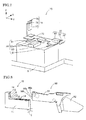
Fig. 2] Fig. 2 is a schematic perspective view illustrating a tape feeder in which a component package tape is set in the automatic tape setting apparatus ofFig. 1 . - [
Fig. 3] Fig. 3 is a schematic perspective view illustrating the component package tape. - [
Fig. 4] Fig. 4 is a schematic perspective view illustrating a feeder holding device of the automatic tape setting apparatus ofFig. 1 . - [
Fig. 5] Fig. 5 is a schematic perspective view illustrating a tape transport device of the automatic tape setting apparatus ofFig. 1 . - [
Fig. 6] Fig. 6 is a schematic perspective view illustrating a tape transfer device of the automatic tape setting apparatus ofFig. 1 . - [
Fig. 7] Fig. 7 is a schematic perspective view illustrating a tape holding releasing device of the automatic tape setting apparatus ofFig. 1 . - [
Fig. 8] Fig. 8 is a first view describing an operation of the automatic tape setting apparatus ofFig. 1 and a perspective view illustrating a state before the tape feeder is held in the feeder holding device. - [
Fig. 9] Fig. 9 is a second view describing the operation of the automatic tape setting apparatus ofFig. 1 and a perspective view illustrating a state after the tape feeder is held in the feeder holding device. - [
Fig. 10] Fig. 10 is a third view describing the operation of the automatic tape setting apparatus ofFig. 1 and a perspective view illustrating a state where the tape transport device and the tape holding releasing device are separated from the feeder holding device. - [
Fig. 11] Fig. 11 is a fourth view describing the operation of the automatic tape setting apparatus ofFig. 1 and a perspective view illustrating a state where the tape transport device and the tape holding releasing device approach the feeder holding device. - [
Fig. 12] Fig. 12 is a fifth view describing the operation of the automatic tape setting apparatus ofFig. 1 and a perspective view illustrating a state before the tape holding releasing device releases a first tape holding section. - [
Fig. 13] Fig. 13 is a sixth view describing the operation of the automatic tape setting apparatus ofFig. 1 and a perspective view illustrating a state after the tape holding releasing device releases the first tape holding section. - [
Fig. 14] Fig. 14 is a seventh view describing the operation of the automatic tape setting apparatus ofFig. 1 and a perspective view illustrating a state immediately before the tape transport device transports the component package tape. - [
Fig. 15] Fig. 15 is an eighth view describing the operation of the automatic tape setting apparatus ofFig. 1 and a perspective view illustrating a state where the tape transport device transports the component package tape to a pitch feed mechanism section. - [
Fig. 16] Fig. 16 is a ninth view describing the operation of the automatic tape setting apparatus ofFig. 1 and a perspective view illustrating a first operation in which the tape transport device sets the component package tape in the pitch feed mechanism section. - [
Fig. 17] Fig. 17 is a tenth view describing the operation of the automatic tape setting apparatus ofFig. 1 and a perspective view illustrating a second operation in which the tape transport device sets the component package tape in the pitch feed mechanism section. - [
Fig. 18] Fig. 18 is an eleventh view describing the operation of the automatic tape setting apparatus ofFig. 1 and a perspective view illustrating a state where the tape transport device sets the component package tape in the pitch feed mechanism section and the tape transfer device grips a top tape. - [
Fig. 19] Fig. 19 is a view corresponding toFig. 15 and a perspective view illustrating a state where the component package tape is bent when the tape transport device transports the component package tape to the pitch feed mechanism section. - [
Fig. 20] Fig. 20 is a view corresponding toFig. 16 and a perspective view illustrating a first operation in which the tape transport device sets the component package tape in the pitch feed mechanism section in a state where the component package tape is bent. - [
Fig. 21] Fig. 21 is a view corresponding toFig. 17 and a perspective view illustrating a second operation in which the tape transport device sets the component package tape in the pitch feed mechanism section in a state where the component package tape is bent. - [
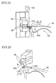
Fig. 22] Fig. 22 is a view corresponding toFig. 18 and a perspective view illustrating a state where the tape transport device sets the component package tape in the pitch feed mechanism section and the tape transfer device grips the top tape in a state where the component package tape is bent. - [
Fig. 23] Fig. 23 is a twelfth view describing the operation of the automatic tape setting apparatus ofFig. 1 and a perspective view illustrating a state where the tape transfer device grips and lifts the top tape. - [
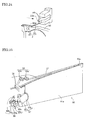
Fig. 24] Fig. 24 is a thirteenth view describing the operation of the automatic tape setting apparatus ofFig. 1 and a perspective view illustrating a state where the tape transfer device peels the top tape from a carrier tape. - [
Fig. 25] Fig. 25 is a fourteenth view describing the operation of the automatic tape setting apparatus ofFig. 1 and a perspective view illustrating a state where the tape transfer device hangs the top tape on a top tape feed guide. - [
Fig. 26] Fig. 26 is a fifteenth view describing the operation of the automatic tape setting apparatus ofFig. 1 and a perspective view illustrating a state before the tape holding releasing device releases a second tape holding section. - [
Fig. 27] Fig. 27 is a sixteenth view describing the operation of the automatic tape setting apparatus ofFig. 1 and a perspective view illustrating a state after the tape holding releasing device releases the second tape holding section. - [
Fig. 28] Fig. 28 is a seventeenth view describing the operation of the automatic tape setting apparatus ofFig. 1 and a perspective view illustrating a state where the tape transfer device sets the top tape in a top tape delivery mechanism section. - Hereinafter, a configuration of an embodiment of an automatic tape setting apparatus of the invention will be described with reference to the drawings. An automatic tape setting apparatus 1 illustrated in
Fig. 1 is an apparatus that automatically and respectively sets acarrier tape 21 and atop tape 22 of acomponent package tape 2 wound around a tape reel 3 that is mounted on atape feeder 90 illustrated inFigs. 2 and 3 in a pitchfeed mechanism section 93 and a top tapedelivery mechanism section 97 of thetape feeder 90. Moreover, a tape transport direction when setting thecomponent package tape 2 is referred to as a Y direction (an up and down direction on a paper surface ofFig. 1 ), a direction orthogonal to the Y direction is referred to as an X direction (a left and right direction on the paper surface ofFig. 1 ), and a vertical direction orthogonal to the Y direction is referred to as a Z direction (a vertical direction on the paper surface ofFig. 1 ). - As illustrated in
Fig. 1 , the automatic tape setting apparatus 1 includes afeeder holding stand 10 that holds thetape feeder 90, atape transport device 30 that transports thecomponent package tape 2, atape transfer device 50 that transfers thetop tape 22, a tape holding releasingdevice 70 that respectively releases holdings of first and secondtape holding sections 95 and 98 (seeFig. 2 ) of thetape feeder 90, and acontrol device 100 that controls operations of thedevices - The
feeder holding stand 10 is disposed substantially at a center of abase stand 5 so that thetape feeder 90 that is held therein faces the Y direction. Thetape transfer device 50 is disposed on thebase stand 5 so as to be along a side (a rear side of thetape feeder 90 illustrated inFig. 2 ) on which the top tapedelivery mechanism section 97 of thetape feeder 90 that is held in thefeeder holding stand 10 is exposed. Thetape transport device 30 and the tape holding releasingdevice 70 are respectively disposed on both sides of thebase stand 5 in the X direction across thetape feeder 90 that is held in thefeeder holding stand 10. Thecontrol device 100 includes a tapetransport control device 101 that controls an operation of thetape transport device 30, a tapetransfer control device 102 that controls an operation of thetape transfer device 50, and a tape holding releasingcontrol device 103 that controls an operation of the tape holding releasingdevice 70. Thefeeder holding stand 10, thetape transport device 30, thetape transfer device 50, and the tape holding releasingdevice 70 are described below in detail. - As illustrated in
Fig. 2 , areel mounting section 92 on which the tape reel 3 around which thecomponent package tape 2 is wound is detachably mounted is provided on a rear end side (the right side inFig. 2 ) of afeeder body 91 of thetape feeder 90. The pitchfeed mechanism section 93 that pitch feeds thecomponent package tape 2 pulled out from the tape reel 3 is provided in an upper portion of a front end side (the left side inFig. 2 ) of thefeeder body 91. Atape feed guide 94 that forms a tape passage guiding thecomponent package tape 2 that is pitch fed is provided between thereel mounting section 92 and the pitchfeed mechanism section 93 in an upper surface portion of thefeeder body 91. - The pitch
feed mechanism section 93 includes asprocket 93a and amotor 93b for rotating thesprocket 93a. Furthermore, the firsttape holding section 95 that holds thecomponent package tape 2 to prevent thecomponent package tape 2 from deviating from the pitchfeed mechanism section 93 when thecomponent package tape 2 is pitch fed is provided in the pitchfeed mechanism section 93. - As illustrated in an enlarged view A of
Fig. 2 , arotation fulcrum 95a that allows the firsttape holding section 95 to be rotatable with respect to thesprocket 93a in a radial direction is provided on a front end side (the left side inFig. 2 ) of the firsttape holding section 95. Alever 95b is protruded and a spring (not illustrated) biasing the firsttape holding section 95 downward is assembled on the rear end side (the right side inFig. 2 ). Holding of the firsttape holding section 95 is released by lifting thelever 95b using a first lever 75 (seeFig. 7 ) of the tape holding releasingdevice 70 described below. - A
tape cover section 95c covering thecomponent package tape 2 is provided in an upper surface portion of the firsttape holding section 95. The front end side (the left side inFig. 2 ) of thetape cover section 95c is opened as a component suction position P and an edge portion of the opening is formed as a toptape peeling section 95d for peeling thetop tape 22 from thecarrier tape 21. - A
power supply terminal 96a that is connected to a power supply section 15 (seeFig. 4 ) of thefeeder holding stand 10 described below and supplies power to a motor 94b of the pitchfeed mechanism section 94, and apositioning pin 96b that determines a holding position with respect to thefeeder holding stand 10 and a component mounting machine (not illustrated) are provided on the front end surface of thefeeder body 91. Moreover, a communication connector that is connected to a communication connector (not illustrated) on the side of the component mounting machine may be provided in thepower supply terminal 96a. - Furthermore, the top tape
delivery mechanism section 97 that delivers thetop tape 22 that is peeled by the toptape peeling section 95d in a direction opposite to the pitch feed direction of thecomponent package tape 2 is provided in a center lower portion of thefeeder body 91. The top tapedelivery mechanism section 97 includes agear 97a and amotor 97b for rotating thegear 97a. Furthermore, the secondtape holding section 98 that holds thetop tape 22 to prevent thetop tape 22 from deviating from the top tapedelivery mechanism section 97 when thetop tape 22 is delivered is provided in the top tapedelivery mechanism section 97. - As illustrated in an enlarged view B of
Fig. 2 , agear 98a that is capable of meshing with thegear 97a of the top tapedelivery mechanism section 97, anarm 98c that has arotation fulcrum 98b allowing thegear 98a to be capable of rotating with respect to thegear 97a in the radial direction, alever 98d that protrudes downward from thearm 98c, and aspring 98e that biases thearm 98c to the side of thegear 97a are provided in the secondtape holding section 98. The holding of the secondtape holding section 98 is released by moving thelever 98d in a direction in which thelever 98d is separated from thegear 97a with a second lever 78 (seeFig. 7 ) of the tape holding releasingdevice 70 described below. - A top
tape feed guide 99 that guides thetop tape 22 peeled by the toptape peeling section 95d to the top tapedelivery mechanism section 97 is provided between the toptape peeling section 95d and the top tapedelivery mechanism section 97 of thefeeder body 91. The toptape feed guide 99 is configured of a pair ofrollers component package tape 2 that is pitch fed on thetape feed guide 94. Oneroller 99a is provided as a roller that applies tension to thetop tape 22 to prevent thetop tape 22 from sagging. - Here, as illustrated in
Fig. 3 , thecomponent package tape 2 is configured to include thecarrier tape 21 in which a component 4 is stored at a predetermined pitch and thetop tape 22 that covers the component 4 by adhering on the upper surface of thecarrier tape 21. Asprocket hole 23 is drilled in one side edge portion of thecomponent package tape 2 at a constant pitch. Thecomponent package tape 2 is pitch fed while teeth of thesprocket 93a are sequentially engaged with the sprocket holes 23 by rotation of thesprocket 93a of the pitchfeed mechanism section 94. Furthermore, thecomponent package tape 2 is formed so that aleading end section 22a of thetop tape 22 protrudes from the leading end of thecarrier tape 21 by a predetermined length. Thecomponent package tape 2 is configured such that theleading end section 22a of thetop tape 22 is gripped by a pair of gripping jaws 56 (seeFig. 6 ) of thetape transfer device 50 described below and thetop tape 22 is peeled from thecarrier tape 21 when the components are supplied. The peeledtop tape 22 is delivered while the teeth of thegear 97a are sequentially engaged with the sprocket holes 23 by rotation of thegear 97a of the top tapedelivery mechanism section 97. - As illustrated in
Figs. 1 and4 , thefeeder holding stand 10 includes astand seat 11 that holds thetape feeder 90 in which the tape reel 3 is mounted on thereel mounting section 92. Thestand seat 11 is provided with a mountingsection 12 on which a bottom surface of thefeeder body 91 is mounted and an abuttingsection 13 against which the front end surface of thefeeder body 91 abuts. A pair of support guides 14 that clamp both lower side surfaces of thefeeder body 91 are provided on the mountingsection 12. The abuttingsection 13 is provided with thepower supply section 15 that supplies power by being connected to thepower supply terminal 96a of thetape feeder 90 and apositioning hole 16 for positioning thetape feeder 90 by inserting thepositioning pin 96b of thetape feeder 90 thereto. - As illustrated in
Figs. 1 and5 , thetape transport device 30 includes afeed device 31 that transports thecomponent package tape 2 that is pulled out from the tape reel 3, aguide 32 that guides the transportedcomponent package tape 2, asupport plate 33 that supports thefeed device 31 and theguide 32, astand seat 34 on which thesupport plate 33 is mounted and fixed, and atransport moving device 35 that moves thestand seat 34 in the X direction. - The
feed device 31 includes a plurality (four in the example) of drivingrollers rollers roller 36a of a starting end and the drivingroller 36b that is arranged next to the drivingroller 36a from below,gear motors rollers sensor 39 that detects the leading end section of thecomponent package tape 2. The fourdriving rollers support plate 33 side by side at predetermined gaps in the Y direction. The drivenrollers rollers -
Guides 32 are respectively disposed on thesupport plate 33 in the front of the drivingroller 36a of the starting end, between the fourdriving rollers roller 36d of the finishing end. Specifically, guides 32a disposed in the front of the drivingroller 36a of the starting end, after the drivingroller 36b arranged next to the drivingroller 36a, and between the drivingrollers rollers rollers guides 32b disposed in the front of the drivingroller 36c arranged next to the drivingroller 36b, after the drivingroller 36d of the finishing end, and between the drivingrollers rollers - When the
tape feeder 90 is held in thefeeder holding stand 10, thetape feed guide 94 of thetape feeder 90 is provided so as to be positioned from the front of the drivingroller 36c arranged next to the drivingroller 36b to a position after the drivingroller 36d of the finishing end. Thus, the transportedcomponent package tape 2 is guided through a gap between theguide 32b and thetape feed guide 94. Meanwhile, thetape feed guide 94 is not provided from the front of the drivingroller 36a of the starting end to the position after the drivingroller 36b arranged next to the drivingroller 36a. Thus, the transportedcomponent package tape 2 is guided through a gap between the pair ofguides 32a. - The
sensor 39 is disposed in thesupport plate 33 so as to be positioned above a tape inlet of the pair ofguides 32a disposed in the front of the drivingroller 36a of the starting end. Thesensor 39 is connected to the tapetransport control device 101 and a detection signal of thesensor 39 is utilized as a trigger signal of rotation of the drivingrollers sprocket 93a by driving of thegear motors motor 93b. - The
transport moving device 35 includes a pair ofrails 40 and anair cylinder 41. The pair ofrails 40 are provided so as to extend in the X direction at a predetermined gap on thebase stand 5. Thestand seat 34 is slidably disposed on the pair ofrails 40 in the X direction. Theair cylinder 41 is disposed between the pair ofrails 40 on thebase stand 5 and is connected to an air supply source (not illustrated), and acylinder rod 41a is connected to thestand seat 34. - As illustrated in
Figs. 1 and6 , thetape transfer device 50 includes a chuck device 51 (corresponding to "clamping means" of the invention) that clamps theleading end section 22a of thetop tape 22, achuck lifting device 52 that lifts thechuck device 51 in the Z direction, astand seat 53 that mounts and fixes thechuck lifting device 52, and achuck moving device 54 that moves thestand seat 53 in the Y direction. - The
chuck device 51 includes adevice body 55, the pair ofgripping jaws 56 that are slidably mounted inside agroove 55a extending in the Z direction provided on the side surface of thedevice body 55, anair cylinder 57 that is built in thedevice body 55 and releases and closes the pair ofgripping jaws 56 in the Z direction, asupport body 58 that slidably supports thedevice body 55 in the X direction inside agroove 58a extending in the X direction provided on the side surface, anair cylinder 59 that is built in thesupport body 58 and moves thedevice body 55 in the X direction, and a sensor 60 (corresponding to "detecting means of the invention") that detects thecomponent package tape 2. - The
chuck lifting device 52 includes a movingbody 61 on which thesupport body 58 of thechuck device 51 is mounted and which moves thesupport body 58 in the Z direction, asupport body 62 that is fixed on thestand seat 53 and slidably supports the movingbody 61 in the Z direction inside agroove 62a extending in the Z direction provided on the side surface, amotor 63 that is disposed on the upper end of thesupport body 62, aball screw 64 extending in the Z direction inside thegroove 62a of thesupport body 62, of which an upper end is connected to a motor shaft of themotor 63 and of which a lower end is rotatably pivoted in abearing 64a fixed on thestand seat 53, and anut 65 that passes through the movingbody 61 and is capable of screwing theball screw 64. - The
chuck moving device 54 includes a pair ofrails 66, aball screw 67, anut 68 that is capable of screwing theball screw 67, and amotor 69. The pair ofrails 66 are provided so as to extend in the Y direction at a predetermined gap on thebase stand 5. Thestand seat 53 is slidably disposed on the pair ofrails 66 in the Y direction. The ball screw 67 is disposed so as to extend in the Y direction on thebase stand 5 and is meshed with thenut 68 passing through thestand seat 53, and of which one end is connected to the motor shaft of themotor 69 fixed on thebase stand 5, and of which the other end is rotatably pivoted on abearing 67a fixed on thebase stand 5. - As illustrated in
Figs. 1 and7 , the tape holding releasingdevice 70 includes a first releasingdevice 71 that is capable of releasing the holding of the firsttape holding section 95, a second releasingdevice 72 that is capable of releasing the holding of the secondtape holding section 98, asupport stand 73 on which the first releasingdevice 71 and the second releasingdevice 72 are fixed and supported, and an releasing movingdevice 74 that moves the support stand 73 in the X direction. - The first releasing
device 71 includes thefirst lever 75 that is capable of moving thelever 95b of the firsttape holding section 95 in the Z direction, a first support stand 76 that supports the leading end of thefirst lever 75 to protrude on the side of thetape feeder 90, and anair cylinder 77 that is fixed on the support stand 73 so that thefirst support stand 76 is capable of moving in the Z direction. The second releasingdevice 72 includes thesecond lever 78 that is capable of moving thelever 98d of the secondtape holding section 98 in the Y direction, a second support stand 79 that supports the leading end of thesecond lever 78 to protrude on the side of thetape feeder 90, and anair cylinder 80 that is fixed on the support stand 73 so that thesecond support stand 79 is movable in the Y direction. - The releasing moving
device 74 includes a pair ofrails 81 and anair cylinder 82. The pair ofrails 81 are provided on thebase stand 5 so as to extend in the X direction at a predetermined gap. The support stand 73 is slidably disposed on the pair ofrails 81 in the X direction. Theair cylinder 82 is disposed between the pair ofrails 81 on thebase stand 5 and is connected to an air supply source (not illustrated), and acylinder rod 82a is connected to thesupport stand 73. - Next, an operation of the automatic tape setting apparatus 1 of the embodiment will be described with reference to the drawings. In an initial state of the automatic tape setting apparatus 1, as illustrated in
Fig. 1 , thetape transfer device 50 and the tape holding releasingdevice 70 are positioned in a state of being separated from thefeeder holding stand 10 at a predetermined distance in the X direction. In this state, as illustrated inFigs. 8 and9 , an operator sets thetape feeder 90 in thefeeder holding stand 10. That is, a bottom surface of thefeeder body 91 is mounted and clamped between the pair of support guides 14 on the mountingsection 12. Thepositioning pin 96b and thepower supply terminal 96a of thefeeder body 91 are respectively inserted into thepositioning hole 16 and thepower supply section 15 of the abuttingsection 13. Then, the tape reel 3 is mounted on thereel mounting section 92 and a feeder set completion button included in thecontrol device 100 of the automatic tape setting apparatus 1 is pressed. - Then, as illustrated in
Fig. 10 , the tapetransport control device 101 and the tape holding releasingcontrol device 103 move thetape transport device 30 and the tape holding releasingdevice 70 in a state where thetape transport device 30 and the tape holding releasingdevice 70 are separated from thefeeder holding stand 10 in the X direction by the predetermined distance in the X direction so as to approach thefeeder holding stand 10. Then, as illustrated inFig. 11 , the tapetransport control device 101 inserts thefeed device 31 and theguide 32 of thetape transport device 30 into thefeeder body 91 of thetape feeder 90 held in thefeeder holding stand 10. Furthermore, the tape holding releasingcontrol device 103 inserts thefirst lever 75 of the first releasingdevice 71 and thesecond lever 78 of the second releasingdevice 72 of the tape holding releasingdevice 70 into the operation side of thelever 95b of the firsttape holding section 95 and into the operation side of thelever 95b of the secondtape holding section 95 of thetape feeder 90 held in the feeder holding stand 10 (seeFigs. 12 and26 ). Then, as illustrated inFigs. 12 and13 , the tape holding releasingcontrol device 103 raises the first support stand 76 of the first releasingdevice 71 of the tape holding releasingdevice 70 in the Z direction and then lifts thelever 95b of the firsttape holding section 95 with thefirst lever 75. Therefore, the firsttape holding section 95 rotates upward about therotation fulcrum 95a and the holding state with the pitchfeed mechanism section 93 is released. - Here, as illustrated in
Fig. 14 , the operator pulls out thecomponent package tape 2 from the tape reel 3 mounted on thereel mounting section 92 of thetape feeder 90 and takes the leading end section (theleading end section 22a of the top tape 22) of thecomponent package tape 2 in a tape entrance 32aa of theguide 32a of thetape transport device 30. When thesensor 39 of thetape transport device 30 detects theleading end section 22a of thetop tape 22 and the detection signal is delivered to the tapetransport control device 101, the tapetransport control device 101 allows the driving of each of thegear motors motor 93b to start, and rotation of each of the drivingrollers sprocket 93a to start. Then, when the operator inserts theleading end section 22a of thetop tape 22 through the tape entrance 32aa of theguide 32a, thecomponent package tape 2 is delivered by each of the drivingrollers guides tape feed guide 94, and passes through a gap between the firsttape holding section 95 and the pitchfeed mechanism section 93. - As illustrated in
Fig. 15 , when thesensor 60 of thetape transfer device 50 detects a boundary between the leading end of thecarrier tape 21 and thetop tape 22 of thecomponent package tape 2 and delivers the detection signal to the tapetransport control device 101, the tapetransport control device 101 allows the driving of thegear motors motor 93b to stop, and rotation of the drivingrollers sprocket 93a to stop. At this time, theleading end section 22a of thetop tape 22 of thecomponent package tape 2 is positioned between the pair of grippingjaws 56. - As illustrated in
Fig. 16 , the tape holding releasingcontrol device 103 allows the first support stand 76 (the first lever 75) of the first releasingdevice 71 to be lowered and the firsttape holding section 95 to be rotated downward about therotation fulcrum 95a, and thecomponent package tape 2 to be held between the firsttape holding section 95 and the pitchfeed mechanism section 93. Then, the tapetransport control device 101 allows themotor 93b to be driven and thesprocket 93a to be rotated, and thecomponent package tape 2 to be transported between the pair ofgripping jaws 56 by the predetermined distance. - As illustrated in
Fig. 17 , the tapetransfer control device 102 allows the pair ofgripping jaws 56 to be moved in a closing direction until the pair of grippingjaws 56 comes into contact with thecomponent package tape 2, that is, immediately before thecomponent package tape 2 is completely gripped. Then, as illustrated inFig. 18 , the tapetransport control device 101 allows themotor 93b to be driven in the opposite direction to the previous direction and thesprocket 93a to be reversely rotated, and thecomponent package tape 2 to be reversely transported between the pair ofgripping jaws 56 by the predetermined distance. Thereafter, the tapetransfer control device 102 allows thetop tape 22 to be completely gripped by the pair of grippingjaws 56. - As described above, it is possible to cope with a case where the
leading end section 22a of thetop tape 22 is bent during transportation of thecomponent package tape 2 in thetape transport device 30 by transporting and reversely transporting thecomponent package tape 2 between the pair ofgripping jaws 56 by the predetermined distance. That is, as illustrated inFig. 19 , when thesensor 60 of thetape transfer device 50 detects the boundary between the leading end of thecarrier tape 21 and thetop tape 22 of thecomponent package tape 2, and delivers the detection signal to the tapetransport control device 101, the tapetransport control device 101 allows the driving of thegear motors motor 93b to stop, and rotation of the drivingrollers sprocket 93a to stop. At this time, theleading end section 22a of thetop tape 22 of thecomponent package tape 2 is bent to the side of thecarrier tape 21. - As illustrated in
Fig. 20 , the tape holding releasingcontrol device 103 allows the first support stand 76 (the first lever 75) of the first releasingdevice 71 to be lowered and the firsttape holding section 95 to be rotated downward about therotation fulcrum 95a, and thecomponent package tape 2 to be held between the firsttape holding section 95 and the pitchfeed mechanism section 93. Then, the tapetransport control device 101 allows themotor 93b to be driven and thesprocket 93a to be rotated, and thecomponent package tape 2 to be transported between the pair ofgripping jaws 56 by the predetermined distance. - As illustrated in
Fig. 21 , the tapetransfer control device 102 allows the pair ofgripping jaws 56 to be moved in the closing direction until the pair of grippingjaws 56 comes into contact with thecomponent package tape 2, that is, immediately before thecomponent package tape 2 is completely gripped. Then, as illustrated inFig. 22 , the tapetransport control device 101 allows themotor 93b to be driven in the opposite direction to the previous direction and thesprocket 93a to be reversely rotated, and thecomponent package tape 2 to be reversely transported between the pair ofgripping jaws 56 by the predetermined distance. At this time, since the bentleading end section 22a of thetop tape 22 of thecomponent package tape 2 is returned so that theleading end section 22a is protruded from the leading end of thecarrier tape 21 by the pair ofgripping jaws 56, it is possible to eliminate the bending of theleading end section 22a of thetop tape 22. Thereafter, the tapetransfer control device 102 allows thetop tape 22 to be completely gripped by the pair of grippingjaws 56. Moreover, when theleading end section 22a of thetop tape 22 is gripped by the pair ofgripping jaws 56, thecomponent package tape 2 may be transported or reversely transported between the pair ofgripping jaws 56 by the predetermined distance or the pair ofgripping jaws 56 may be transported or reversely transported by the predetermined distance in the Y direction. - When the tape
transfer control device 102 allows thetop tape 22 to be completely gripped by the pair ofgripping jaws 56, the tapetransport control device 101 allows thetape transport device 30 to be separated from thefeeder holding stand 10 in the X direction by the predetermined distance. That is, when the tapetransfer control device 102 controls thechuck moving device 54 of thetape transfer device 50 and a tape setdevice 50A (seeFig. 6 ) formed of thechuck device 51 and thechuck lifting device 52 on thestand seat 53 is moved in the Y direction, the tapetransport control device 101 allows thetape transport device 30 to be moved to the position where the tape setdevice 50A and thetape transport device 30 do not interfere with each other. Then, as illustrated inFigs. 23 and24 , the tapetransfer control device 102 allows the pair ofgripping jaws 56 to be raised to lift thetop tape 22 and the pair ofgripping jaws 56 to be moved to the rear end side of thefeeder body 91, and thetop tape 22 to be engaged with the toptape peeling section 95d. Furthermore, the pair ofgripping jaws 56 are moved to the rear end side of thefeeder body 91 and as illustrated inFig. 25 , theleading end section 22a of thetop tape 22 is hanged on therollers tape feed guide 99 in an S shape. At this time, the tapetransfer control device 102 synchronously controls a transfer operation on thetop tape 22 of the pair ofgripping jaws 56 and a pitch feed operation on thecomponent package tape 2 of the pitchfeed mechanism section 93 to smoothly transfer thetop tape 22. - Meanwhile, as illustrated in
Figs. 26 and 27 , the tape holding releasingcontrol device 103 allows the second support stand 79 of the second releasingdevice 72 of the tape holding releasingdevice 70 to be moved in the Y direction and thearm 98c of the secondtape holding section 98 to be rotated to the rear end side of thefeeder body 91 around therotation fulcrum 98b using thesecond lever 78. Therefore, since thegear 98a of the secondtape holding section 98 is separated from thegear 97a of the top tapedelivery mechanism section 97, a holding state with the top tapedelivery mechanism section 97 is released. - Then, as illustrated in
Fig. 28 , the tapetransfer control device 102 allows the pair ofgripping jaws 56 to be lowered and theleading end section 22a of thetop tape 22 to pass through between thegear 98a of the secondtape holding section 98 and thegear 97a of the top tapedelivery mechanism section 97. At this time, thetop tape 22 intersects thecomponent package tape 2 during transportation, but is engaged with anotch 91a provided inside thefeeder body 91 so as to straddle thecomponent package tape 2, and interference with thecomponent package tape 2 is prevented. - Thereafter, the tape holding releasing
control device 103 allows the second support stand 79 of the second releasingdevice 72 to be moved in the Y direction and thearm 98c of the secondtape holding section 98 to be rotated to the front end side of thefeeder body 91 around therotation fulcrum 98b, and thetop tape 22 to be held between thegear 98a of the secondtape holding section 98 and thegear 97a of the top tapedelivery mechanism section 97. Then, the tapetransfer control device 102 allows the pair ofgripping jaws 56 to be moved in the releasing direction and the gripping on thetop tape 22 to be released. Then, the tapetransfer control device 102 allows the pair ofgripping jaws 56 to be moved in the Y direction and returned to an original standby position, that is, to a position on the leading end side of thefeeder body 91. - The tape
transfer control device 102 allows themotor 93b to be driven and thesprocket 93a to be rotated, and performs cueing of the component 4 stored in thecarrier tape 21, that is, positioning of the component 4, in the component suction position P. Then, the operator cuts the deliveredcarrier tape 21 ahead of the component 4 positioned in the component suction position P. The tape holding releasingcontrol device 103 allows the tape holding releasingdevice 70 to be separated from thefeeder holding stand 10 in the X direction by the predetermined distance. In this manner, the automatic setting of thecomponent package tape 2 with respect to thetape feeder 90 is completed, and thus the operator removes thetape feeder 90 from thefeeder holding stand 10 and sets thetape feeder 90 to the component mounting machine. - As described above, according to the automatic tape setting apparatus 1 of the embodiment, the
tape transport device 30 transports thecomponent package tape 2 that is pulled out from the tape reel 3 to the pitchfeed mechanism section 93. Then, the tape holding releasingdevice 70 holds thecomponent package tape 2 in the firsttape holding section 95 that is in the released state. Furthermore, thetape transfer device 70 clamps theleading end section 22a of thetop tape 22 adhered to thecarrier tape 21 that is transported to the pitchfeed mechanism section 93 and transfers thetop tape 22 to the top tapedelivery mechanism section 97 after peeling thetop tape 22 from thecarrier tape 21 with the toptape peeling section 95d. Then, the tape holding releasingdevice 70 holds thetop tape 22 in the secondtape holding section 98 that is in the released state. Therefore, since it is not necessary to respectively provide pull-out sections in thecarrier tape 21 and thetop tape 22 and it is not necessary to prepare a dedicated tape feeder in which the transport path through which the pull-out sections pass is provided as the related art, it is possible to use the general-purpose tape feeder 90 and it is possible to suppress the cost. Furthermore, since thecarrier tape 21 and thetop tape 22 can be automatically and reliably set in the pitchfeed mechanism section 93 and in the top tapedelivery mechanism section 97, respectively, only by entering thecomponent package tape 2 that is pulled out from the tape reel 3 into thetape transport device 30, it is possible to significantly reduce the setting time. - Furthermore, when the
top tape 22 is transferred and set in the top tapedelivery mechanism section 97, the tapetransfer control device 102 of thecontrol device 100 synchronously controls the transfer operation of thetape transfer device 50 and the pitch feed operation of the pitchfeed mechanism section 93. Therefore, it is possible to smoothly peel thetop tape 22 from thecarrier tape 21 and it is possible to automatically and reliably set thetop tape 22 in the top tapedelivery mechanism section 97 by preventing thetop tape 22 from being cut during transferring. - Furthermore, the
power supply section 15 of thefeeder holding stand 10 supplies power to the pitchfeed mechanism section 93 of thetape feeder 90 that is held in thefeeder holding stand 10. Therefore, it is possible to further reduce the setting time since it is possible to start setting of thecomponent package tape 2 by simply holding thetape feeder 90 in thefeeder holding stand 10 and it is not necessary to connect the power supply source to thetape feeder 90 when performing substituting operation of the tape reel 3. - Furthermore, the
feed device 31 of thetape transport device 30 pulls out thecomponent package tape 2 from the tape reel3 while pinching thecomponent package tape 2 and thecomponent package tape 2 is transported to the pitchfeed mechanism section 93 by thefeed device 31 while being guided by theguide 32. Therefore, it is possible to transport thecomponent package tape 2 to the pitchfeed mechanism section 93 with high accuracy. - Furthermore, when the
top tape 22 is clamped by thechuck device 51, the tapetransfer control device 102 of thecontrol device 100 can allow thecomponent package tape 2 to be moved in the transport direction and the reverse transport direction with respect to thechuck device 51 by the predetermined distance. Therefore, even when thetop tape 22 is bent in the reverse transport direction during transportation of thecomponent package tape 2, it is possible to return thetop tape 22 to a state before thetop tape 22 is bent by moving thecomponent package tape 2 in the transport direction and the reverse transport direction as described above. - Furthermore, when the
component package tape 2 is set in the pitchfeed mechanism section 93, thetransport moving device 35 and the releasing movingdevice 74 allow thetape transport device 30 and the tape holding releasingdevice 74 to approach thetape feeder 90. Therefore, since thetape transport device 30 and the tape holding releasingdevice 70 are separated from thetape feeder 90 before thecomponent package tape 2 is set, it is possible to easily set thetape feeder 90 in thefeeder holding stand 10. Furthermore, when thetop tape 22 is set in the top tapedelivery mechanism section 97, thetransport moving device 35 allows thetape transport device 30 to be separated from thetape feeder 90. Therefore, it is possible to automatically and reliably set thetop tape 22 in the top tapedelivery mechanism section 97 without interfering with thetape transport device 30 during operation of thetape transfer device 50. - Moreover, in the embodiments described above, the
transport moving device 35 of thetape transport device 30, thechuck device 51 of thetape transfer device 50, the first releasingdevice 71 and the second releasingdevice 72 of the tape holding releasingdevice 70 are configured including the air cylinders, but may be configured including motors, ball screw mechanisms, belt mechanisms or the like. Furthermore, thechuck lifting device 52 and thechuck moving device 54 of thetape transfer device 50 are configured including the motor and the ball screw mechanism, but may be configured including the motor and the belt mechanism. Furthermore, thechuck moving device 54 of thetape transfer device 50 may be configured including a cam mechanism in which a member in which a groove cam is formed is mounted on thestand seat 11 of thefeeder holding stand 10 and a cam follower is mounted on thechuck device 51. - The automatic tape setting apparatus of the invention is capable of being applied to a case where the component package tape is automatically set in the tape feeder on which the tape reel around which the component package tape is wound is mounted.
- 1: automatic tape setting apparatus, 2: component package tape, 21: carrier tape, 22: top tape, 3: tape reel, 10: feeder holding stand, 15: power supply section, 30: tape transport device, 31: feed device, 32: guide, 35: transport moving device, 50: tape transfer device, 51: chuck device, 60: sensor, 70: tape holding releasing device, 71: first releasing device, 72: second releasing device, 74: releasing moving device, 90: tape feeder, 92: reel mounting section, 93: pitch feed mechanism section, 94: tape feed guide, 95: first tape holding section, 95d: top tape peeling section, 97: top tape delivery mechanism section, 98: second tape holding section, 99: top tape feed guide, 100: control device, 101: tape transport control device, 102: tape transfer control device, 103: tape holding releasing control device
Claims (6)
- An automatic tape setting apparatus that automatically sets a component package tape in a tape feeder including:a pitch feed mechanism section that pitch feeds the component package tape from a tape reel around which the component package tape in which a top tape is adhered to an upper surface of a carrier tape in which components are stored at predetermined pitches is wound to a component suction position;a first tape holding section that is provided in the pitch feed mechanism section and holds the component package tape to prevent the component package tape that is pitch fed from deviating from the pitch feed mechanism section;a top tape peeling section that is provided in the first tape holding section and peels the top tape from the component package tape;a top tape delivery mechanism section that delivers the top tape that is peeled from the component package tape in the top tape peeling section in a direction opposite to a pitch feed direction of the component package tape; anda second tape holding section that is provided in the top tape delivery mechanism section and holds the top tape that is delivered,the automatic tape setting apparatus comprising:a feeder holding stand that holds the tape feeder in which the tape reel is mounted on the reel mounting section;a tape transport device that transports the component package tape pulled out from the tape reel to the pitch feed mechanism section;a tape transfer device that clamps a leading end of the top tape adhered to the carrier tape that is transported to the pitch feed mechanism section and peels the top tape from the carrier tape in the top tape peeling section, and then transfers the top tape to the top tape delivery mechanism section; anda tape holding releasing device that releases holding of the first tape holding section when the component package tape is transported by the tape transport device and set to the pitch feed mechanism section; holds the component package tape in the first tape holding section after the component package tape is set; releases holding of the second tape holding section when the top tape is transferred by the tape transfer device and set to the top tape delivery mechanism section; and holds the top tape in the second tape holding section after the top tape is set.
- The automatic tape setting apparatus according to claim 1,
wherein a tape transfer control device is provided that transfers and sets the top tape to the top tape delivery mechanism section by synchronously controlling a transfer operation of the tape transfer device and a pitch feed operation of the pitch feed mechanism section. - The automatic tape setting apparatus according to claim 1 or 2,
wherein the feeder holding stand is provided with a power supply section that supplies power at least to the pitch feed mechanism section. - The automatic tape setting apparatus according to any one of claims 1 to 3,
wherein the tape transport device is provided with a feed device that pinches and pulls out the component package tape from the tape reel and then transports the component package tape to the pitch feed mechanism section, and a guide that guides the transported component package tape. - The automatic tape setting apparatus according to any one of claims 1 to 4,
wherein the tape transfer device is provided with clamping means for clamping the top tape and detecting means for detecting a predetermined position of the transported component package tape on a leading end side, and
wherein the automatic tape setting apparatus is provided with a tape transfer control device that temporarily stops the transport of the component package tape when the predetermined position is detected by the detecting means, and sets one of the component package tape and the clamping means in the pitch feed mechanism section after moving the one of the component package tape and the clamping means in a transport direction and a reverse transport direction of the component package tape by a predetermined distance. - The automatic tape setting apparatus according to any one of claims 1 to 5,
wherein the tape transport device and the tape holding releasing device are respectively disposed on both sides across the tape feeder that is held in the feeder holding stand,
wherein the tape transport device is provided with a transport moving device that allows the tape transport device to approach the tape feeder when the component package tape is automatically set in the pitch feed mechanism section and allows the tape transport device to be detached from the tape feeder when the top tape is automatically set in the top tape delivery mechanism section, and
wherein the tape holding releasing device is provided with a releasing moving device that allows the tape holding releasing device to approach the tape feeder when the component package tape is automatically set in the pitch feed mechanism section and when the top tape is automatically set in the top tape delivery mechanism section, and allows the tape holding releasing device to be detached from the tape feeder after setting of the top tape is completed.
Applications Claiming Priority (1)
| Application Number | Priority Date | Filing Date | Title |
|---|---|---|---|
| PCT/JP2012/055717 WO2013132599A1 (en) | 2012-03-06 | 2012-03-06 | Automated tape setting apparatus |
Publications (3)
| Publication Number | Publication Date |
|---|---|
| EP2825013A1 true EP2825013A1 (en) | 2015-01-14 |
| EP2825013A4 EP2825013A4 (en) | 2015-11-25 |
| EP2825013B1 EP2825013B1 (en) | 2017-11-29 |
Family
ID=49116115
Family Applications (1)
| Application Number | Title | Priority Date | Filing Date |
|---|---|---|---|
| EP12870400.4A Active EP2825013B1 (en) | 2012-03-06 | 2012-03-06 | Automated tape setting apparatus |
Country Status (5)
| Country | Link |
|---|---|
| US (1) | US9736970B2 (en) |
| EP (1) | EP2825013B1 (en) |
| JP (1) | JP5877891B2 (en) |
| CN (1) | CN104247588B (en) |
| WO (1) | WO2013132599A1 (en) |
Cited By (3)
| Publication number | Priority date | Publication date | Assignee | Title |
|---|---|---|---|---|
| EP3771309A4 (en) * | 2018-03-21 | 2021-03-31 | Fuji Corporation | AUTOMATIC TAPE LOADING DEVICE AND CORRESPONDING TAPE BINDING METHOD |
| EP3780928A4 (en) * | 2018-04-12 | 2021-04-14 | Fuji Corporation | Tape autoloading device |
| EP3860327A4 (en) * | 2018-09-26 | 2021-10-06 | Fuji Corporation | BAND FEED ELEMENT ADJUSTMENT WORK DEVICE |
Families Citing this family (27)
| Publication number | Priority date | Publication date | Assignee | Title |
|---|---|---|---|---|
| US9669980B2 (en) * | 2012-03-13 | 2017-06-06 | Fuji Machine Mfg. Co., Ltd. | Feeder management system of component mounting apparatus |
| EP2830406B1 (en) * | 2012-03-22 | 2017-05-31 | Fuji Machine Mfg. Co., Ltd. | Tape feeder |
| EP2938177B1 (en) * | 2012-12-21 | 2017-10-18 | Fuji Machine Mfg. Co., Ltd. | Automatic tape processing apparatus and automatic tape setting apparatus |
| DE102014201674A1 (en) * | 2013-10-14 | 2015-04-16 | Kampf Schneid- Und Wickeltechnik Gmbh & Co. Kg | Transport device for web and / or band-shaped material |
| US8960999B1 (en) | 2014-03-28 | 2015-02-24 | Gudpod Holdings, Llc | System for mixing beverages and method of doing the same |
| CN107710905B (en) * | 2015-06-18 | 2019-11-15 | 株式会社富士 | Belt cutting processing device and processing method |
| US10015919B2 (en) * | 2016-02-26 | 2018-07-03 | Panasonic Intellectual Property Management Co., Ltd. | Component supply device |
| CN108781527B (en) * | 2016-03-30 | 2020-06-23 | 雅马哈发动机株式会社 | Component supply device |
| JP6735835B2 (en) * | 2016-08-30 | 2020-08-05 | 株式会社Fuji | Splicing device |
| JP6535883B2 (en) * | 2016-10-11 | 2019-07-03 | パナソニックIpマネジメント株式会社 | Component supply device and component mounter |
| JP7170198B2 (en) * | 2017-06-21 | 2022-11-14 | パナソニックIpマネジメント株式会社 | Component supply device, tape peeling method in component supply device |
| US11229148B2 (en) * | 2017-07-18 | 2022-01-18 | Fuji Corporation | Component mounting machine |
| JP7126056B2 (en) * | 2017-08-21 | 2022-08-26 | パナソニックIpマネジメント株式会社 | PARTS SUPPLY DEVICE AND TAPE SEPARATING METHOD IN PARTS SUPPLY DEVICE |
| US11778799B2 (en) | 2018-02-20 | 2023-10-03 | Fuji Corporation | Tape feeder support plate type/component type combination verification system and support plate type/component type combination verification method |
| CN108437437A (en) * | 2018-05-17 | 2018-08-24 | 深圳市永顺创能技术有限公司 | A kind of high-precision adjustment platform |
| JP7158176B2 (en) * | 2018-05-18 | 2022-10-21 | 株式会社Fuji | Automatic tape loading device |
| JP7136589B2 (en) * | 2018-05-18 | 2022-09-13 | 株式会社Fuji | TAPE LOADING DEVICE AND TAPE CONNECTING METHOD |
| CN110407007A (en) * | 2019-08-29 | 2019-11-05 | 郑州为新科技有限公司 | A kind of V method moulding film drawing device |
| DE112020004881T5 (en) | 2019-10-11 | 2022-06-30 | Panasonic Intellectual Property Management Co., Ltd. | Component feeding apparatus and cover tape detachment method |
| CN110996643A (en) * | 2019-12-05 | 2020-04-10 | 深圳市宝尔威精密机械有限公司 | Glue feeding and stripping mechanism of material belt connecting machine |
| JP7367189B2 (en) | 2020-03-31 | 2023-10-23 | 株式会社Fuji | tape loading device |
| CN111469415A (en) * | 2020-04-18 | 2020-07-31 | 福建恒安集团有限公司 | Nose bridge strip welding device |
| CN113291906B (en) * | 2021-03-02 | 2022-12-06 | 阿里巴巴(中国)有限公司 | Garment web gripping device, component, placement table and related method |
| KR20230037210A (en) * | 2021-09-09 | 2023-03-16 | 에스케이온 주식회사 | Apparatus for feeding tape for secondary batteryg |
| DE112022006609T5 (en) | 2022-02-07 | 2024-11-28 | Fuji Corporation | bobbin loading device |
| WO2023161999A1 (en) * | 2022-02-22 | 2023-08-31 | 株式会社Fuji | Tape conveyance assistance device and automatic tape loading device |
| JPWO2024247349A1 (en) * | 2023-05-30 | 2024-12-05 |
Family Cites Families (13)
| Publication number | Priority date | Publication date | Assignee | Title |
|---|---|---|---|---|
| JPS5175686A (en) | 1974-12-27 | 1976-06-30 | Mitsubishi Rayon Co | ANIONKOKANSEISENIJOBUTSUNOSEIHO |
| US5191693A (en) * | 1989-12-29 | 1993-03-09 | Canon Kabushiki Kaisha | Tape type work conveying method and conveying apparatus |
| JPH05175686A (en) * | 1991-07-23 | 1993-07-13 | Matsushita Electric Works Ltd | Tape reel and tape-component feed apparatus |
| JPH0955599A (en) * | 1995-08-12 | 1997-02-25 | Denso Corp | Electronic component mounting device |
| JPH1187991A (en) | 1997-09-10 | 1999-03-30 | Toshiba Fa Syst Eng Kk | Automatic setup device for chip type taping |
| US7220095B2 (en) | 2001-05-24 | 2007-05-22 | Lyndaker David W | Self-threading component tape feeder |
| JP3995486B2 (en) | 2002-01-29 | 2007-10-24 | 株式会社日立ハイテクインスツルメンツ | Taping parts cueing device |
| JP4820728B2 (en) * | 2006-10-03 | 2011-11-24 | ヤマハ発動機株式会社 | Component supply device and surface mounter |
| JP4863956B2 (en) * | 2007-09-18 | 2012-01-25 | 富士機械製造株式会社 | Tape feeder |
| US7819239B2 (en) * | 2008-12-11 | 2010-10-26 | Schenson Co., Ltd. | Feeder for an auto mounting device |
| JP5384309B2 (en) * | 2009-12-02 | 2014-01-08 | 株式会社日立ハイテクインスツルメンツ | Feeder and electronic component mounting apparatus |
| US8678065B2 (en) * | 2010-03-30 | 2014-03-25 | Sts Co., Ltd. | Carrier tape feeder |
| JP5650428B2 (en) * | 2010-04-01 | 2015-01-07 | 株式会社日立ハイテクインスツルメンツ | Electronic component feeder |
-
2012
- 2012-03-06 WO PCT/JP2012/055717 patent/WO2013132599A1/en not_active Ceased
- 2012-03-06 JP JP2014503327A patent/JP5877891B2/en active Active
- 2012-03-06 US US14/383,001 patent/US9736970B2/en active Active
- 2012-03-06 EP EP12870400.4A patent/EP2825013B1/en active Active
- 2012-03-06 CN CN201280071177.XA patent/CN104247588B/en active Active
Cited By (4)
| Publication number | Priority date | Publication date | Assignee | Title |
|---|---|---|---|---|
| EP3771309A4 (en) * | 2018-03-21 | 2021-03-31 | Fuji Corporation | AUTOMATIC TAPE LOADING DEVICE AND CORRESPONDING TAPE BINDING METHOD |
| EP3780928A4 (en) * | 2018-04-12 | 2021-04-14 | Fuji Corporation | Tape autoloading device |
| EP3860327A4 (en) * | 2018-09-26 | 2021-10-06 | Fuji Corporation | BAND FEED ELEMENT ADJUSTMENT WORK DEVICE |
| US11737252B2 (en) | 2018-09-26 | 2023-08-22 | Fuji Corporation | Tape-feeder setting work apparatus |
Also Published As
| Publication number | Publication date |
|---|---|
| JP5877891B2 (en) | 2016-03-08 |
| US20150047788A1 (en) | 2015-02-19 |
| JPWO2013132599A1 (en) | 2015-07-30 |
| EP2825013A4 (en) | 2015-11-25 |
| CN104247588B (en) | 2017-03-22 |
| EP2825013B1 (en) | 2017-11-29 |
| WO2013132599A1 (en) | 2013-09-12 |
| US9736970B2 (en) | 2017-08-15 |
| CN104247588A (en) | 2014-12-24 |
Similar Documents
| Publication | Publication Date | Title |
|---|---|---|
| EP2825013B1 (en) | Automated tape setting apparatus | |
| CN101784181B (en) | Apparatus for supplying electronic parts and chip mounter having the same | |
| CN104885588B (en) | With automatic processing device and with automatic placing device | |
| JP6363606B2 (en) | Component mounting equipment | |
| JP6331122B2 (en) | Component supply apparatus and component supply method | |
| US20180376630A1 (en) | Tape cutting processing apparatus and processing method | |
| US9801319B2 (en) | Tape feeder | |
| CN101181834B (en) | Method for cutting protective tape of semiconductor wafer and apparatus for cutting the protective tape | |
| US10159170B2 (en) | Feeder | |
| CN112429564B (en) | Automatic reel changing system | |
| EP3151647B1 (en) | Feeder | |
| CN111771430B (en) | with automatic filling device | |
| JP7158176B2 (en) | Automatic tape loading device | |
| EP3313160A1 (en) | Feeder | |
| JP6247000B2 (en) | Film feeder and assembly machine | |
| KR101823926B1 (en) | Automatic supply apparatus of carrier tape | |
| JP7350879B2 (en) | Tape automatic loading system | |
| JP2888818B1 (en) | Terminal processing device for wire winding bobbin | |
| JP6586620B2 (en) | feeder | |
| JP2019149586A (en) | Component mounting device | |
| US20260097918A1 (en) | Reel loading device | |
| WO2024028933A1 (en) | Tape guide attachment/detachment device and tape guide attachment/detachment method | |
| WO2023162227A1 (en) | Tape working device and reel loading device | |
| JPH04271197A (en) | Taped part supply device | |
| JPH0457118B2 (en) |
Legal Events
| Date | Code | Title | Description |
|---|---|---|---|
| PUAI | Public reference made under article 153(3) epc to a published international application that has entered the european phase |
Free format text: ORIGINAL CODE: 0009012 |
|
| 17P | Request for examination filed |
Effective date: 20140905 |
|
| AK | Designated contracting states |
Kind code of ref document: A1 Designated state(s): AL AT BE BG CH CY CZ DE DK EE ES FI FR GB GR HR HU IE IS IT LI LT LU LV MC MK MT NL NO PL PT RO RS SE SI SK SM TR |
|
| AX | Request for extension of the european patent |
Extension state: BA ME |
|
| DAX | Request for extension of the european patent (deleted) | ||
| RA4 | Supplementary search report drawn up and despatched (corrected) |
Effective date: 20151023 |
|
| RIC1 | Information provided on ipc code assigned before grant |
Ipc: H05K 13/02 20060101AFI20151019BHEP |
|
| GRAP | Despatch of communication of intention to grant a patent |
Free format text: ORIGINAL CODE: EPIDOSNIGR1 |
|
| INTG | Intention to grant announced |
Effective date: 20170728 |
|
| GRAS | Grant fee paid |
Free format text: ORIGINAL CODE: EPIDOSNIGR3 |
|
| GRAA | (expected) grant |
Free format text: ORIGINAL CODE: 0009210 |
|
| AK | Designated contracting states |
Kind code of ref document: B1 Designated state(s): AL AT BE BG CH CY CZ DE DK EE ES FI FR GB GR HR HU IE IS IT LI LT LU LV MC MK MT NL NO PL PT RO RS SE SI SK SM TR |
|
| REG | Reference to a national code |
Ref country code: CH Ref legal event code: EP |
|
| REG | Reference to a national code |
Ref country code: AT Ref legal event code: REF Ref document number: 951474 Country of ref document: AT Kind code of ref document: T Effective date: 20171215 |
|
| REG | Reference to a national code |
Ref country code: IE Ref legal event code: FG4D |
|
| REG | Reference to a national code |
Ref country code: DE Ref legal event code: R096 Ref document number: 602012040460 Country of ref document: DE |
|
| REG | Reference to a national code |
Ref country code: NL Ref legal event code: MP Effective date: 20171129 |
|
| REG | Reference to a national code |
Ref country code: LT Ref legal event code: MG4D |
|
| REG | Reference to a national code |
Ref country code: AT Ref legal event code: MK05 Ref document number: 951474 Country of ref document: AT Kind code of ref document: T Effective date: 20171129 |
|
| PG25 | Lapsed in a contracting state [announced via postgrant information from national office to epo] |
Ref country code: SE Free format text: LAPSE BECAUSE OF FAILURE TO SUBMIT A TRANSLATION OF THE DESCRIPTION OR TO PAY THE FEE WITHIN THE PRESCRIBED TIME-LIMIT Effective date: 20171129 Ref country code: NO Free format text: LAPSE BECAUSE OF FAILURE TO SUBMIT A TRANSLATION OF THE DESCRIPTION OR TO PAY THE FEE WITHIN THE PRESCRIBED TIME-LIMIT Effective date: 20180228 Ref country code: ES Free format text: LAPSE BECAUSE OF FAILURE TO SUBMIT A TRANSLATION OF THE DESCRIPTION OR TO PAY THE FEE WITHIN THE PRESCRIBED TIME-LIMIT Effective date: 20171129 Ref country code: LT Free format text: LAPSE BECAUSE OF FAILURE TO SUBMIT A TRANSLATION OF THE DESCRIPTION OR TO PAY THE FEE WITHIN THE PRESCRIBED TIME-LIMIT Effective date: 20171129 Ref country code: FI Free format text: LAPSE BECAUSE OF FAILURE TO SUBMIT A TRANSLATION OF THE DESCRIPTION OR TO PAY THE FEE WITHIN THE PRESCRIBED TIME-LIMIT Effective date: 20171129 |
|
| PG25 | Lapsed in a contracting state [announced via postgrant information from national office to epo] |
Ref country code: LV Free format text: LAPSE BECAUSE OF FAILURE TO SUBMIT A TRANSLATION OF THE DESCRIPTION OR TO PAY THE FEE WITHIN THE PRESCRIBED TIME-LIMIT Effective date: 20171129 Ref country code: GR Free format text: LAPSE BECAUSE OF FAILURE TO SUBMIT A TRANSLATION OF THE DESCRIPTION OR TO PAY THE FEE WITHIN THE PRESCRIBED TIME-LIMIT Effective date: 20180301 Ref country code: AT Free format text: LAPSE BECAUSE OF FAILURE TO SUBMIT A TRANSLATION OF THE DESCRIPTION OR TO PAY THE FEE WITHIN THE PRESCRIBED TIME-LIMIT Effective date: 20171129 Ref country code: RS Free format text: LAPSE BECAUSE OF FAILURE TO SUBMIT A TRANSLATION OF THE DESCRIPTION OR TO PAY THE FEE WITHIN THE PRESCRIBED TIME-LIMIT Effective date: 20171129 Ref country code: HR Free format text: LAPSE BECAUSE OF FAILURE TO SUBMIT A TRANSLATION OF THE DESCRIPTION OR TO PAY THE FEE WITHIN THE PRESCRIBED TIME-LIMIT Effective date: 20171129 Ref country code: BG Free format text: LAPSE BECAUSE OF FAILURE TO SUBMIT A TRANSLATION OF THE DESCRIPTION OR TO PAY THE FEE WITHIN THE PRESCRIBED TIME-LIMIT Effective date: 20180228 |
|
| PG25 | Lapsed in a contracting state [announced via postgrant information from national office to epo] |
Ref country code: NL Free format text: LAPSE BECAUSE OF FAILURE TO SUBMIT A TRANSLATION OF THE DESCRIPTION OR TO PAY THE FEE WITHIN THE PRESCRIBED TIME-LIMIT Effective date: 20171129 |
|
| PG25 | Lapsed in a contracting state [announced via postgrant information from national office to epo] |
Ref country code: CZ Free format text: LAPSE BECAUSE OF FAILURE TO SUBMIT A TRANSLATION OF THE DESCRIPTION OR TO PAY THE FEE WITHIN THE PRESCRIBED TIME-LIMIT Effective date: 20171129 Ref country code: CY Free format text: LAPSE BECAUSE OF FAILURE TO SUBMIT A TRANSLATION OF THE DESCRIPTION OR TO PAY THE FEE WITHIN THE PRESCRIBED TIME-LIMIT Effective date: 20171129 Ref country code: DK Free format text: LAPSE BECAUSE OF FAILURE TO SUBMIT A TRANSLATION OF THE DESCRIPTION OR TO PAY THE FEE WITHIN THE PRESCRIBED TIME-LIMIT Effective date: 20171129 Ref country code: EE Free format text: LAPSE BECAUSE OF FAILURE TO SUBMIT A TRANSLATION OF THE DESCRIPTION OR TO PAY THE FEE WITHIN THE PRESCRIBED TIME-LIMIT Effective date: 20171129 Ref country code: SK Free format text: LAPSE BECAUSE OF FAILURE TO SUBMIT A TRANSLATION OF THE DESCRIPTION OR TO PAY THE FEE WITHIN THE PRESCRIBED TIME-LIMIT Effective date: 20171129 |
|
| REG | Reference to a national code |
Ref country code: DE Ref legal event code: R097 Ref document number: 602012040460 Country of ref document: DE |
|
| PG25 | Lapsed in a contracting state [announced via postgrant information from national office to epo] |
Ref country code: IT Free format text: LAPSE BECAUSE OF FAILURE TO SUBMIT A TRANSLATION OF THE DESCRIPTION OR TO PAY THE FEE WITHIN THE PRESCRIBED TIME-LIMIT Effective date: 20171129 Ref country code: RO Free format text: LAPSE BECAUSE OF FAILURE TO SUBMIT A TRANSLATION OF THE DESCRIPTION OR TO PAY THE FEE WITHIN THE PRESCRIBED TIME-LIMIT Effective date: 20171129 Ref country code: SM Free format text: LAPSE BECAUSE OF FAILURE TO SUBMIT A TRANSLATION OF THE DESCRIPTION OR TO PAY THE FEE WITHIN THE PRESCRIBED TIME-LIMIT Effective date: 20171129 Ref country code: PL Free format text: LAPSE BECAUSE OF FAILURE TO SUBMIT A TRANSLATION OF THE DESCRIPTION OR TO PAY THE FEE WITHIN THE PRESCRIBED TIME-LIMIT Effective date: 20171129 |
|
| PLBE | No opposition filed within time limit |
Free format text: ORIGINAL CODE: 0009261 |
|
| STAA | Information on the status of an ep patent application or granted ep patent |
Free format text: STATUS: NO OPPOSITION FILED WITHIN TIME LIMIT |
|
| REG | Reference to a national code |
Ref country code: DE Ref legal event code: R082 Ref document number: 602012040460 Country of ref document: DE Representative=s name: GRUENECKER PATENT- UND RECHTSANWAELTE PARTG MB, DE Ref country code: DE Ref legal event code: R081 Ref document number: 602012040460 Country of ref document: DE Owner name: FUJI CORPORATION, CHIRYU-SHI, JP Free format text: FORMER OWNER: FUJI MACHINE MFG. CO., LTD., CHIRYU, AICHI, JP |
|
| REG | Reference to a national code |
Ref country code: CH Ref legal event code: PL |
|
| 26N | No opposition filed |
Effective date: 20180830 |
|
| GBPC | Gb: european patent ceased through non-payment of renewal fee |
Effective date: 20180306 |
|
| PG25 | Lapsed in a contracting state [announced via postgrant information from national office to epo] |
Ref country code: SI Free format text: LAPSE BECAUSE OF FAILURE TO SUBMIT A TRANSLATION OF THE DESCRIPTION OR TO PAY THE FEE WITHIN THE PRESCRIBED TIME-LIMIT Effective date: 20171129 Ref country code: MC Free format text: LAPSE BECAUSE OF FAILURE TO SUBMIT A TRANSLATION OF THE DESCRIPTION OR TO PAY THE FEE WITHIN THE PRESCRIBED TIME-LIMIT Effective date: 20171129 |
|
| REG | Reference to a national code |
Ref country code: BE Ref legal event code: MM Effective date: 20180331 |
|
| REG | Reference to a national code |
Ref country code: IE Ref legal event code: MM4A |
|
| PG25 | Lapsed in a contracting state [announced via postgrant information from national office to epo] |
Ref country code: LU Free format text: LAPSE BECAUSE OF NON-PAYMENT OF DUE FEES Effective date: 20180306 |
|
| PG25 | Lapsed in a contracting state [announced via postgrant information from national office to epo] |
Ref country code: IE Free format text: LAPSE BECAUSE OF NON-PAYMENT OF DUE FEES Effective date: 20180306 |
|
| PG25 | Lapsed in a contracting state [announced via postgrant information from national office to epo] |
Ref country code: GB Free format text: LAPSE BECAUSE OF NON-PAYMENT OF DUE FEES Effective date: 20180306 Ref country code: CH Free format text: LAPSE BECAUSE OF NON-PAYMENT OF DUE FEES Effective date: 20180331 Ref country code: LI Free format text: LAPSE BECAUSE OF NON-PAYMENT OF DUE FEES Effective date: 20180331 Ref country code: BE Free format text: LAPSE BECAUSE OF NON-PAYMENT OF DUE FEES Effective date: 20180331 |
|
| PG25 | Lapsed in a contracting state [announced via postgrant information from national office to epo] |
Ref country code: FR Free format text: LAPSE BECAUSE OF NON-PAYMENT OF DUE FEES Effective date: 20180331 |
|
| PG25 | Lapsed in a contracting state [announced via postgrant information from national office to epo] |
Ref country code: MT Free format text: LAPSE BECAUSE OF NON-PAYMENT OF DUE FEES Effective date: 20180306 |
|
| PG25 | Lapsed in a contracting state [announced via postgrant information from national office to epo] |
Ref country code: TR Free format text: LAPSE BECAUSE OF FAILURE TO SUBMIT A TRANSLATION OF THE DESCRIPTION OR TO PAY THE FEE WITHIN THE PRESCRIBED TIME-LIMIT Effective date: 20171129 |
|
| PG25 | Lapsed in a contracting state [announced via postgrant information from national office to epo] |
Ref country code: PT Free format text: LAPSE BECAUSE OF FAILURE TO SUBMIT A TRANSLATION OF THE DESCRIPTION OR TO PAY THE FEE WITHIN THE PRESCRIBED TIME-LIMIT Effective date: 20171129 Ref country code: HU Free format text: LAPSE BECAUSE OF FAILURE TO SUBMIT A TRANSLATION OF THE DESCRIPTION OR TO PAY THE FEE WITHIN THE PRESCRIBED TIME-LIMIT; INVALID AB INITIO Effective date: 20120306 |
|
| PG25 | Lapsed in a contracting state [announced via postgrant information from national office to epo] |
Ref country code: MK Free format text: LAPSE BECAUSE OF NON-PAYMENT OF DUE FEES Effective date: 20171129 |
|
| PG25 | Lapsed in a contracting state [announced via postgrant information from national office to epo] |
Ref country code: AL Free format text: LAPSE BECAUSE OF FAILURE TO SUBMIT A TRANSLATION OF THE DESCRIPTION OR TO PAY THE FEE WITHIN THE PRESCRIBED TIME-LIMIT Effective date: 20171129 Ref country code: IS Free format text: LAPSE BECAUSE OF FAILURE TO SUBMIT A TRANSLATION OF THE DESCRIPTION OR TO PAY THE FEE WITHIN THE PRESCRIBED TIME-LIMIT Effective date: 20180329 |
|
| P01 | Opt-out of the competence of the unified patent court (upc) registered |
Effective date: 20230328 |
|
| PGFP | Annual fee paid to national office [announced via postgrant information from national office to epo] |
Ref country code: DE Payment date: 20260128 Year of fee payment: 15 |