EP2824981B1 - Method for controlling service in radio communication system - Google Patents
Method for controlling service in radio communication system Download PDFInfo
- Publication number
- EP2824981B1 EP2824981B1 EP13758097.3A EP13758097A EP2824981B1 EP 2824981 B1 EP2824981 B1 EP 2824981B1 EP 13758097 A EP13758097 A EP 13758097A EP 2824981 B1 EP2824981 B1 EP 2824981B1
- Authority
- EP
- European Patent Office
- Prior art keywords
- service
- request
- mme
- sms
- terminal
- Prior art date
- Legal status (The legal status is an assumption and is not a legal conclusion. Google has not performed a legal analysis and makes no representation as to the accuracy of the status listed.)
- Active
Links
- 238000000034 method Methods 0.000 title claims description 65
- 238000004891 communication Methods 0.000 title claims description 17
- 230000004044 response Effects 0.000 description 21
- 230000008859 change Effects 0.000 description 8
- 230000004048 modification Effects 0.000 description 5
- 238000012986 modification Methods 0.000 description 5
- 230000001960 triggered effect Effects 0.000 description 4
- CSRZQMIRAZTJOY-UHFFFAOYSA-N trimethylsilyl iodide Substances C[Si](C)(C)I CSRZQMIRAZTJOY-UHFFFAOYSA-N 0.000 description 4
- 230000009849 deactivation Effects 0.000 description 3
- 238000010295 mobile communication Methods 0.000 description 3
- 230000008569 process Effects 0.000 description 3
- 230000011664 signaling Effects 0.000 description 3
- 241000276398 Opsanus tau Species 0.000 description 2
- 230000000694 effects Effects 0.000 description 2
- 239000012729 immediate-release (IR) formulation Substances 0.000 description 2
- 238000013507 mapping Methods 0.000 description 2
- 238000013475 authorization Methods 0.000 description 1
- 230000005713 exacerbation Effects 0.000 description 1
- 230000000977 initiatory effect Effects 0.000 description 1
- 238000007726 management method Methods 0.000 description 1
- 238000012545 processing Methods 0.000 description 1
- 238000010187 selection method Methods 0.000 description 1
- 230000008054 signal transmission Effects 0.000 description 1
- 230000000007 visual effect Effects 0.000 description 1
Images


Classifications
-
- H—ELECTRICITY
- H04—ELECTRIC COMMUNICATION TECHNIQUE
- H04W—WIRELESS COMMUNICATION NETWORKS
- H04W76/00—Connection management
- H04W76/20—Manipulation of established connections
- H04W76/27—Transitions between radio resource control [RRC] states
-
- H—ELECTRICITY
- H04—ELECTRIC COMMUNICATION TECHNIQUE
- H04W—WIRELESS COMMUNICATION NETWORKS
- H04W36/00—Hand-off or reselection arrangements
- H04W36/12—Reselecting a serving backbone network switching or routing node
-
- H—ELECTRICITY
- H04—ELECTRIC COMMUNICATION TECHNIQUE
- H04W—WIRELESS COMMUNICATION NETWORKS
- H04W28/00—Network traffic management; Network resource management
- H04W28/02—Traffic management, e.g. flow control or congestion control
- H04W28/0289—Congestion control
-
- H—ELECTRICITY
- H04—ELECTRIC COMMUNICATION TECHNIQUE
- H04W—WIRELESS COMMUNICATION NETWORKS
- H04W36/00—Hand-off or reselection arrangements
- H04W36/0005—Control or signalling for completing the hand-off
- H04W36/0055—Transmission or use of information for re-establishing the radio link
- H04W36/0079—Transmission or use of information for re-establishing the radio link in case of hand-off failure or rejection
-
- H—ELECTRICITY
- H04—ELECTRIC COMMUNICATION TECHNIQUE
- H04W—WIRELESS COMMUNICATION NETWORKS
- H04W60/00—Affiliation to network, e.g. registration; Terminating affiliation with the network, e.g. de-registration
-
- H—ELECTRICITY
- H04—ELECTRIC COMMUNICATION TECHNIQUE
- H04W—WIRELESS COMMUNICATION NETWORKS
- H04W68/00—User notification, e.g. alerting and paging, for incoming communication, change of service or the like
- H04W68/02—Arrangements for increasing efficiency of notification or paging channel
-
- H—ELECTRICITY
- H04—ELECTRIC COMMUNICATION TECHNIQUE
- H04W—WIRELESS COMMUNICATION NETWORKS
- H04W76/00—Connection management
- H04W76/10—Connection setup
- H04W76/11—Allocation or use of connection identifiers
-
- H—ELECTRICITY
- H04—ELECTRIC COMMUNICATION TECHNIQUE
- H04W—WIRELESS COMMUNICATION NETWORKS
- H04W76/00—Connection management
- H04W76/10—Connection setup
- H04W76/18—Management of setup rejection or failure
-
- H—ELECTRICITY
- H04—ELECTRIC COMMUNICATION TECHNIQUE
- H04W—WIRELESS COMMUNICATION NETWORKS
- H04W76/00—Connection management
- H04W76/30—Connection release
- H04W76/34—Selective release of ongoing connections
-
- H—ELECTRICITY
- H04—ELECTRIC COMMUNICATION TECHNIQUE
- H04W—WIRELESS COMMUNICATION NETWORKS
- H04W76/00—Connection management
- H04W76/50—Connection management for emergency connections
-
- H—ELECTRICITY
- H04—ELECTRIC COMMUNICATION TECHNIQUE
- H04W—WIRELESS COMMUNICATION NETWORKS
- H04W80/00—Wireless network protocols or protocol adaptations to wireless operation
- H04W80/04—Network layer protocols, e.g. mobile IP [Internet Protocol]
-
- H—ELECTRICITY
- H04—ELECTRIC COMMUNICATION TECHNIQUE
- H04W—WIRELESS COMMUNICATION NETWORKS
- H04W36/00—Hand-off or reselection arrangements
- H04W36/0005—Control or signalling for completing the hand-off
- H04W36/0055—Transmission or use of information for re-establishing the radio link
-
- H—ELECTRICITY
- H04—ELECTRIC COMMUNICATION TECHNIQUE
- H04W—WIRELESS COMMUNICATION NETWORKS
- H04W8/00—Network data management
- H04W8/02—Processing of mobility data, e.g. registration information at HLR [Home Location Register] or VLR [Visitor Location Register]; Transfer of mobility data, e.g. between HLR, VLR or external networks
- H04W8/06—Registration at serving network Location Register, VLR or user mobility server
- H04W8/065—Registration at serving network Location Register, VLR or user mobility server involving selection of the user mobility server
-
- H—ELECTRICITY
- H04—ELECTRIC COMMUNICATION TECHNIQUE
- H04W—WIRELESS COMMUNICATION NETWORKS
- H04W8/00—Network data management
- H04W8/02—Processing of mobility data, e.g. registration information at HLR [Home Location Register] or VLR [Visitor Location Register]; Transfer of mobility data, e.g. between HLR, VLR or external networks
- H04W8/08—Mobility data transfer
- H04W8/082—Mobility data transfer for traffic bypassing of mobility servers, e.g. location registers, home PLMNs or home agents
Definitions
- the present disclosure relates to a method and apparatus that control communication services in a wireless communication system without increasing network load.
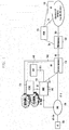
- FIG. 1 illustrates an architecture of the LTE mobile communication system.
- the radio access network (EUTRAN) of the LTE mobile communication system is composed of an evolved base station (Evolved Node B, ENB or Node B) 105, Mobility Management Entity (MME) 110, and Serving Gateway (S-GW) 115.
- Evolved Node B Evolved Node B
- MME Mobility Management Entity
- S-GW Serving Gateway
- a user equipment (UE or terminal) 100 may connect to an external network through the ENB 110, S-GW 115 and PDN Gateway (P-GW) 120.
- P-GW PDN Gateway
- Application Function (AF) 130 is an entity that provides session related information to user applications.
- the PCRF 125 is an entity for controlling policies related to user QoS. Policy and charging control (PCC) rules corresponding to a specific policy are sent to the P-GW 120 for enforcement.
- PCC Policy and charging control
- the ENB 105 is a radio access network (RAN) node, which corresponds to the RNC of the UTRAN system or the BSC of the GERAN system.
- the ENB 105 is connected with the UE 100 through a wireless channel and functions similarly to the existing RNC or BSC.
- RAN radio access network
- the S-GW 115 provides data bearers, and creates and removes a data bearer under control of the MME 110.
- the MME 110 performs various control functions, and may be connected to multiple base stations.
- PCRF Policy Charging and Rules Function
- an aspect of the present disclosure is to provide a method and apparatus that can generate, when a request for a circuit switched voice network (CS) service is issued to a user having subscribed only to a packet switched data network (PS) service, a service restriction notification without increasing network load.
- CS circuit switched voice network
- PS packet switched data network
- a method for signal transmission and reception in a user equipment of a wireless communication system may include: sending a request for a Circuit Switched voice network (CS) service to a Gateway Mobile Switching Center (GMSC) to send and receive data to and from a second user equipment; and receiving a call reject response corresponding to the service request from the GMSC, wherein the call reject response is sent by an entity in a core network of the second user equipment.
- CS Circuit Switched voice network
- GMSC Gateway Mobile Switching Center
- a method for congestion control in a user equipment of a wireless communication system may include: sending a Non-Access-Stratum (NAS) request to a base station; receiving a NAS reject response corresponding to the request from a core network; and sending a Radio Resource Control (RRC) connection setup signal containing an indicator indicating necessity of release of an RRC connection between the user equipment and base station to the base station.
- NAS Non-Access-Stratum
- RRC Radio Resource Control
- a user equipment in a wireless communication system may include: a transceiver unit to send a request for a Circuit Switched voice network (CS) service to a Gateway Mobile Switching Center (GMSC) to send and receive data to and from a second user equipment; and a control unit to control the transceiver unit to receive a call reject response corresponding to the service request from the GMSC, wherein the call reject response is sent by an entity in a core network of the second user equipment.
- CS Circuit Switched voice network
- GMSC Gateway Mobile Switching Center
- a user equipment supporting congestion control may include: a transceiver unit to send a Non-Access-Stratum (NAS) request to a base station and to receive a NAS reject response due to congestion, corresponding to the request, from a core network; and a control unit to control the transceiver unit to send a Radio Resource Control (RRC) connection setup signal containing an indicator indicating necessity of release of an RRC connection between the user equipment and base station to the base station.
- NAS Non-Access-Stratum
- RRC Radio Resource Control
- the description related to the LTE system may be applied to the UTRAN/GERAN system having similar system architecture.
- the ENB RAN node
- the MME may be replaced with the SGSN
- the S-GW may be omitted or be included in the SGSN
- the P-GW may correspond to the GGSN.
- Bearers in the LTE system may correspond to PDP context in the UTRAN/GERAN system.
- each communication entity may include a transceiver unit to exchange signals with another entity, and a control unit to control the transceiver unit and perform operations on the basis of signals exchanged through the transceiver unit .
- a user equipment may include a display unit to present a visual signal to a user.
- CS circuit switched voice network
- PS packet switched data network
- a particular user may have a subscription to only a PS service.
- a user having only a PS service subscription may receive an SMS service but may be not allowed to receive a CS service without a separate measure. That is, it may be assumed that a particular user is allowed to receive a PS data service and SMS service but is not allowed to receive a CS service such as a voice call (such a user is referred to as a PS-only-with-SMS user).
- a mobile terminating CS service request (e.g. a voice call) may be issued to the PS-only-with-SMS user.
- a random call for advertisement or promotion may be placed without consideration of a recipient phone number.
- a voice call may be wrongly placed to a phone number that had been previously assigned to a voice call subscriber and has been reassigned to a PS-only-with-SMS subscriber.
- a mobile terminating CS service request (voice call) is issued to a PS-only-with-SMS user
- the network may have to perform signaling such as subscriber location identification and paging.
- signaling such as subscriber location identification and paging.
- the PS-only-with-SMS user cannot receive a CS service like a voice call, such a signaling procedure is useless but merely increases network load.
- a procedure is proposed as follows.
- the operator network may determine that the user equipment is detached from a CS service (i.e. reject voice call or disallow CS service). More specifically, the following schemes may be used.
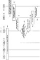
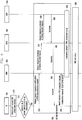
- FIG. 2 illustrates a procedure for signal exchange according to the first embodiment, wherein Home Location Register (HLR) is responsible for determination.
- HLR Home Location Register
- a first user equipment (UE1) 201 is registered as a PS-only-with-SMS terminal in at least one of the MME 202, MSC 203 and HLR 204.
- the UE1 201 registered as a PS-only-with-SMS terminal may receive only a PS data service or a SMS service.
- PS-only-with-SMS may be given to a user equipment not allowed to receive a CS service.
- a second user equipment (UE2) 206 being unaware that the UE1 201 is a PS-only-with-SMS terminal, makes a voice call to the UE1 201.
- a request for any CS service may be issued.
- the UE2 206 sends a request for placing a voice call destined for the UE1 201 to Gateway Mobile Switching Center (GMSC) 205.
- GMSC Gateway Mobile Switching Center
- the GMSC 205 Upon reception of the voice call request, at operation 225, to find an MSC/VLR at which the corresponding subscriber is located, the GMSC 205 transmits a Send Routing Information (SRI) Request message to the HLR 204.
- This message may include a service indicator indicating the requested service (voice call or SMS, or CS service other than SMS).
- the HLR 204 checks whether the request destined for the UE1 201 is SMS according to UE registration information and examines subscription information of the UE1 201. If the request destined for the UE1 201 is SMS, the HLR 204 may forward the request to the MSC 203 in which the UE1 201 is registered.
- the HLR 204 may regard the UE1 201 as being detached from the requested service.
- the HLR 204 sends a message indicating call rejection as a response to SRI to the GMSC 205.
- the call reject message may include information notifying PS-only-with-SMS subscription.
- a Send Routing Information Response message may be used. Another type message may also be used.
- the GMSC 205 Upon reception of a negative response, at operation 240, not to retry paging, the GMSC 205 stops the paging retry timer.
- the GMSC 205 sends a notification indicating failure of a voice call (CS service other than SMS) attempt to the sender network, which then notifies the sender (UE2 206) that the request for a CS service other than SMS (voice call) is denied because of recipient's PS-only-with-SMS subscription and an SMS service is available.
- the GMSC 205 may directly send such notification to the sender terminal 206, or may send such notification to a corresponding to MSC of the sender network and the MSC may forward the notification to the sender terminal 206 via RNC (BSC) .
- the sender terminal 206 may store the received information or notify the user of the same.
- the sender terminal 206 may notify the user of the received information by means of sound output or screen output.
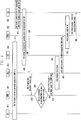
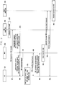
- FIG. 3 illustrates another procedure for signal exchange according to the first embodiment.
- a first user equipment (UE1) 301 is registered as a PS-only-with-SMS terminal in at least one of the MME 302, MSC 303 and HLR 304.
- the UE1 301 registered as a PS-only-with-SMS terminal may receive only a PS data service or a SMS service .
- a second user equipment (UE2) 306 being unaware that the UE1 301 is a PS-only-with-SMS terminal, makes a voice call to the UE1 301.
- the UE2 306 sends a voice call request to the GMSC 305.
- the GMSC 305 transmits an IAM message to the MSC 303 at which the UE1 301 is located.
- the IAM message may include a service indicator indicating the requested service (voice call or SMS, or CS service other than SMS).
- the MSC 303 checks whether the request destined for the UE1 301 is SMS. If the request destined for the UE1 301 is SMS, the MSC 303 sends a paging request to the MME 302 in which the UE1 301 is registered. If the request destined for the UE1 301 is a CS service (e.g. voice call), at operation 335, the MSC 303 sends a message indicating that the UE1 301 is registered as a PS-only-with-SMS terminal to the GMSC 305. Here, this message may be a call reject message, which may include a cause of rejection. At operation 335, the MSC 303 may use an RCH message or another type message to notify that the UE1 301 is registered as PS-only-with-SMS.
- CS service e.g. voice call
- the GMSC 305 After reception of a negative response, the GMSC 305 performs operation 340 and operation 345, which are identical respectively to operation 240 and operation 245 in FIG. 2 .
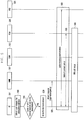
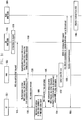
- FIG. 4 illustrates another procedure for signal exchange according to the first embodiment.
- a first user equipment (UE1) 401 is registered as a PS-only-with-SMS terminal in at least one of the MME 402, MSC 403 and HLR 404.
- the UE1 401 may receive only a PS data service or a SMS service.
- a second user equipment (UE2) 406 being unaware that the UE1 401 has a PS-only-with-SMS subscription, makes a voice call to the UE1 401.
- the UE2 406 sends a voice call request to the GMSC 405.
- the GMSC 405 transmits an IAM message to the MSC 403 at which the UE1 401 is located.
- the IAM message may include a service indicator indicating the requested service (voice call or SMS, or CS service other than SMS).
- the MSC 403 sends a paging request message to the MME 402.
- the paging request message may be a SGs_Paging_Req message, which may include an indicator to a service to be provided by paging.
- the MME 402 checks whether the request destined for the UE1 401 is SMS. If the request destined for the UE1 401 is SMS, the MME 402 may perform further processing.
- the MME 402 sends a message indicating that the UE1 401 is registered as a PS-only-with-SMS terminal to the MSC 403.
- this message may be a paging reject message, which may include a cause of rejection.
- the MME 402 may also use a SGs paging reject message or another type message.
- the MSC 403 Upon reception of a negative response such as paging reject, at operation 445, not to retry paging, the MSC 403 stops the paging retry timer.
- the MSC 403 notifies the GMSC 405 of voice call rejection.
- a call reject message including a cause of rejection may be sent to the GMSC 405 to notify the sender network of failure of a voice call attempt.
- operation 455 and operation 460 in the sender network are performed in a manner identical respectively to operation 240 and operation 245 in FIG. 2 .
- the maximum number of simultaneously activatable bearers in a user equipment may be limited according to implementation. Typical user equipments may simultaneously activate up to one, three or five bearers.
- the number of simultaneously active bearers may exceed the maximum number of bearers supportable by the user equipment when an emergency call is placed in a state wherein the number of normal bearers currently active for system attachment has reached the maximum number of supportable bearers, or when multiple bearers needed to provide an emergency service are simultaneously created (for example, while the maximum number of supportable bearers is three, the number of active normal bearers is two and the number of emergency bearers needed is two). In this case, for emergency service provisioning, it is necessary to release normal bearers and create emergency bearers.
- the user equipment may perform normal bearer cleanup first and then perform emergency bearer setup, or may simultaneously issue an emergency bearer setup request and a normal bearer cleanup request.
- the user equipment may send a normal bearer deactivation request to the network, or may locally deactivate normal bearers and notify the core network of a bearer context state through TAU.
- the core network e.g. MME
- the core network may automatically perform normal bearer cleanup for the user equipment. More specifically, the following schemes may be used.
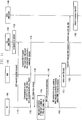
- FIG. 5 illustrates a procedure for signal exchange according to the second example.
- FIG. 5 depicts emergency service provisioning through the attach procedure.
- a UE 501 may exchange signals with a network composed of the MME 502, S-GW 503, P-GW 504 and HSS 505.
- the UE 501 may exchange signals with the network via a base station (ENB).
- ENB base station
- the UE 501 detects a user request for an emergency service.
- the UE 501 identifies the number of currently active bearers.
- the number of currently active bearers may be the number of normal bearers.
- the UE 501 may determine whether some or all of the currently active bearers are to be deactivated on the basis of the number of currently active bearers, the number of bearers to be used for the emergency service, and the number of simultaneously supportable bearers.
- the UE 501 may determine that the number of simultaneously active bearers fails to accommodate the number of bearers to be used for the emergency service.
- the UE 501 may exchange signals with the MME 502 to establish a call for the emergency service .
- the UE 501 performs local detach.
- the UE 501 may autonomously conduct the local detach procedure.
- the UE 501 performs a re-attach procedure for the emergency service in cooperation with the MME 502.
- This procedure may be initiated by sending an attach request, and the attach request may include an indication to the service or call type.
- the core network Upon reception of the attach request from the UE 501, at operation 530 and at operation 535, the core network identifies emergency attach from the attach request, and performs cleanup of existing normal bearers and generation of emergency bearers by means of authentication and authorization, and bearer context setup.
- an IMS call is set up between the UE 501 and the core network.
- FIG. 6 illustrates another procedure for signal exchange according to the second example.
- FIG. 6 depicts a scheme in which the user equipment explicitly makes a normal bearer cleanup request.
- a UE 601 may exchange signals with a network composed of the MME 602, S-GW 603 and P-GW 604.
- the UE 601 may exchange signals with the network via a base station (ENB).
- ENB base station
- the UE 601 detects a user request for an emergency service.
- the UE 601 identifies the number of currently active bearers.
- the number of currently active bearers may be the number of normal bearers.
- the UE 601 may determine whether some or all of the currently active bearers are to be deactivated on the basis of the number of currently active bearers, the number of bearers to be used for the emergency service, and the number of simultaneously supportable bearers.
- the UE 601 may determine that the number of simultaneously active bearers fails to accommodate the number of bearers to be used for the emergency service.
- the UE 601 may exchange signals with the MME 602 to establish a call for the emergency service .
- the UE 601 sends a request for releasing a normal bearer or normal PDN connection to the core network.
- this request may be sent to the MME 602 through a bearer resource modification request or PDN disconnection request.
- the MME 602 Upon reception of the request, at operation 625, the MME 602 forwards the received request to the S-GW 603 through a bearer resource command or a delete session request.
- the S-GW 603 Upon reception of the request, at operation 630, the S-GW 603 forwards the received request to the P-GW 605 through a bearer resource command or a delete session request.
- a response to the request is sent by the P-GW 604 via the S-GW 603 and the MME 602 to the UE 601.
- the UE 601 may be detached.
- the UE 601 sends an Attach request or PDN connectivity request to the MME 602.
- This request may include type information indicating "emergency”.
- an emergency PDN connectivity request may be sent. In the event that all bearers have been released, as the UE 601 is detached, an emergency attach request may be sent.
- At operation 660 at least one of the emergency attach procedure and the emergency PDN connection procedure may be performed.
- an IMS call is set up.
- the UE 601 may locally deactivate existing bearers and notify the core network of this deactivation through a TAU procedure. More specifically, in response to a user request for an emergency service, when some or all of existing bearers are to be deactivated, the UE 601 selects bearers to be deactivated and sends a TAU request message containing information on the remaining active EPS bearers (except for the selected bearers) to the core network (active bits of the EPS bearer context status are set in the TAU request message). The UE 601 may also send a TAU request message containing bearer information (bearers to be deactivated are marked as inactive and bearers to be kept are marked as active) to the core network.
- the UE 601 may notify the core network of the emergency service request by setting the EPS update type of the TAU request.
- the UE 601 may notify the core network of the emergency service request by using an additional update type of the TAU request.
- the UE 601 may also notify the core network of the emergency service request by using a separate emergency indicator of the TAU request.
- the UE 601 may notify the core network of S1/S5 setup for the following emergency service by setting the active flag of the TAU request.
- the MME 602 may be aware that the UE 601 has changed the bearer context for the emergency service.
- the MME 602 compares the pre-stored EPS bearer context status with the EPS bearer context status in the TAU request received from the UE 601 and may perform bearer cleanup if an EPS bearer to be deactivated is present.
- the MME 602 may send a TAU accept response to the UE 601 before completion of bearer cleanup.
- the UE 601 may be aware of completion of requested bearer context status update, and may perform a subsequent procedure for the emergency service.
- the UE 601 selects bearers to be deactivated and sends a TAU request containing information on the remaining active EPS bearers (except for the selected bearers) to the core network (active bits of the EPS bearer context status are set in the TAU request message).
- the UE 601 may also send a TAU request message containing bearer information (bearers to be deactivated are marked as inactive and bearers to be kept are marked as active) to the core network.
- the UE 601 has to establish an RRC connection with the ENB.
- the UE 601 may send an RRC connection setup request whose establishment cause is set to "emergency".
- the ENB forwards the TAU request message contained in an RRC message received from the UE 601 through S1-AP Initial UE message.
- the ENB may forward this together with the TAU request message.
- the MME 602 may be aware that the UE 601 has sent the TAU request for an emergency service. Thereafter, subsequent operations may be processed as described before.
- the UE 601 is depicted as notifying the network of information on locally deactivated bearers using a TAU message .
- the same procedure may be applied to 2G/3G networks using a Routing Area Update (RAU) message.
- the UE 601 may send an Extended Service Request (ESR) message having bearer status information instead of a TAU message having bearer status information.
- ESR Extended Service Request
- FIG. 7 illustrates another procedure for signal exchange according to the second example.
- FIG. 7 depicts a signal exchange scheme in which cleanup of existing bearers and creation of new emergency bearers are simultaneously performed.
- a UE 701 may exchange signals with a network composed of the ENB 702, MME 703, S-GW 704 and P-GW 705.
- the UE 701 detects a user request for an emergency service.
- the UE 701 identifies the number of currently active bearers.
- the number of currently active bearers may be the number of normal bearers.
- the UE 701 may determine whether some or all of the currently active bearers are to be deactivated on the basis of the number of currently active bearers, the number of bearers to be used for the emergency service, and the number of simultaneously supportable bearers.
- the UE 701 may determine that the number of simultaneously active bearers fails to accommodate the number of bearers to be used for the emergency service.
- the UE 701 may exchange signals with the MME 703 to establish a call for the emergency service .
- the UE 701 selects bearers to be deactivated and sends a PDN connectivity request message containing information on the remaining active EPS bearers (except for the selected bearers) to the MME 703 (active bits of the EPS bearer context status are set in the PDN connectivity request message).
- the UE 701 may also send a PDN connectivity request message containing bearer information (bearers to be deactivated are marked as inactive and bearers to be kept are marked as active) to the MME 703.
- the UE 701 may select bearers to be removed according to a criteria based on ARP, QCI, default/dedicated bearer (a dedicated bearer is removed), or inactivity duration.
- the MME 703 may be aware that the UE 701 has changed the bearer context for the emergency service.
- the MME 703 compares the pre-stored EPS bearer context status with the EPS bearer context status in the PDN connectivity request received from the UE 701 and may perform bearer cleanup if an EPS bearer to be deactivated is present.
- the MME 602 may also perform bearer cleanup on the basis of information received at operation 715.
- the MME 703 may perform a PDN connection creation procedure for the emergency service.
- the MME 703 sends a Create Session Request to the S-GW 704.
- This Create Session Request may contain IDs of bearers to be removed.
- the S-GW 704 forwards the Create Session Request received at operation 725 to the P-GW 705.
- each node sends or forwards a response message.
- the ENB 702 may send an RRC connection Reconfiguration to the UE 701. This RRC connection Reconfiguration may contain a DBR list.
- an IMS call is set up between the UE 701 and core network.
- FIG. 8 illustrates another procedure for signal exchange according to the second example.
- a UE 801 requests the network to clean up existing normal bearers and to create bearers for an emergency service.
- the UE 601 may exchange signals with a network composed of the ENB 802, MME 803, S-GW 804 and P-GW 805.
- Operation 810 and operation 815 are identical respectively to operation 710 and operation 715 in FIG. 7 .
- the UE 801 sends an Emergency PDN connectivity request containing a cleanup indicator to existing bearers.
- This request may also include information on the number of bearers simultaneously supportable by the UE 801.
- the MME 803 may autonomously perform bearer cleanup. In the case wherein the number of supportable bearers in the UE 801 is not known to the core network when the UE 801 has issued a bearer cleanup request, the MME 803 may simply remove all normal bearers.
- the MME 803 may be aware of the maximum number of simultaneously supportable bearers in the UE 801 according to user subscription information.
- the context table in the UE 801 may have a mapping to the maximum number of supportable bearers based on ISMI, or the maximum number of active bearers may be known according to the model of the UE 801 based on IMEISV.
- the MME 803 may have to store mappings for UE models based on : IMEISV and the maximum number of active bearers in each UE model.
- the operator may update UE information in the HSS or may set information on the IMEISV-based model of the UE 801 and the maximum number of bearers corresponding to the model in the MME 803 through O&M configuration or the like.
- the MME 803 may determine that some or all of normal bearers are to be removed on the basis of information on the UE 801 and the maximum number of supportable bearers. When only some of normal bearers are to be removed, selection of bearers to be removed may be performed according to a criteria based on ARP, QCI, default/dedicated bearer (a dedicated bearer is removed), or inactivity duration.
- the core network removes corresponding active normal bearers (bearer cleanup from the S-GW 804 to the P-GW 805) and creates emergency bearers/sessions.
- cleanup of existing bearers and creation of new emergency bearers may be simultaneously performed or separately performed in sequence.
- a list of bearers to be removed or a cleanup indicator indicating removal of all normal bearers may be inserted in the Create session request message for emergency bearer creation.
- the MME 803 notifies the ENB 802 of information on removed bearers and newly created bearers (bearer ID, bearer QoS, S5 TEID or the like) .
- the ENB 802 updates data radio bearers related to the UE 801 accordingly.
- the core network may remove the indicated active normal bearers (bearer cleanup from the S-GW 804 to the P-GW 805) and perform emergency bearer/session creation.
- cleanup of existing bearers and creation of new emergency bearers may be simultaneously performed or separately performed in sequence.
- a list of bearers to be removed or a cleanup indicator indicating removal of all normal bearers may be inserted in the Create session request message for emergency bearer creation.
- the MME 803 notifies the ENB 802 of information on removed bearers and newly created bearers (bearer ID, bearer QoS, S5 TEID or the like) .
- the ENB 802 updates data radio bearers related to the UE 801 accordingly. Finally, this update is known to the UE 801.
- merging of the EMM process and the ESM process is proposed. That is, a TAU/RAU request message or ESR message containing an ESM message container is transmitted.
- an ESM request message (e.g. PDN connectivity request) created by the UE 801 may be contained in the ESM message container.
- the UE 801 upon emergency service initiation, sends information on locally deactivated bearers through a TAU/RAU request message or an ESR message, whose ESM message container includes a PDN connectivity request.
- the UE 801 inserts information on locally deactivated bearers or information on the remaining active bearers after deactivation in the EPS bearer context status IE of a TAU request, RAU request or ESR message, inserts a PDN connectivity request for the emergency service in the ESM message container thereof, and sends the TAU request, RAU request or ESR message to the MME 803.
- the MME 803 may not only perform bearer cleanup for the UE 801 according to the above embodiments but also handle a PDN connection creation request using the PDN connectivity request contained in the ESM message container.
- information elements contained in each signal may be used interchangeably.
- the core network node may redirect user equipments being served so that the user equipments can be served by another core network node.
- This process may be realized through a procedure performed by a base station node to newly select a core network node for a user equipment and through a procedure to register UE information in the core network node.
- congestion may be not resolved.
- the core network node serving a user equipment is changed after a new core network node is selected by the base station node, it is necessary to register UE information in the new core network node.
- making an information request to the previous core network node may exacerbate conditions of the previous core network node already in congestion.
- a core network node in congestion may notify a user equipment of difficulty of service provisioning owing to congestion through NAS layer information.
- the user equipment does not provide information enabling identification of the previous core network node (e.g. S-TMSI, GUTI, GUMMEI, or P-TMSI) to the lower layer (AS layer) during reconfiguration of core network registration.
- the AS layer of the user equipment cannot provide information thereon when an RRC connection is established with the base station, causing the base station to select a new core network node for the user equipment.
- a NAS request message (e.g. attach request) from the user equipment is delivered to the newly selected core network node via the base station.
- the user equipment may provide the new core network node with information (or indicator) that directs the new core network node to directly communicate with the HSS to thereby configure UE context information.
- FIG. 9 illustrates a procedure for signal exchange according to the third example.
- a UE 901 may exchange signals with the MME/SGSN 903 or 904 via the RAN 902.
- the MME/SGSN 903 or 904 may be referred to as old MME/SGSN 903 (to which a connection has been made) or referred to as new MME/SGSN 904 (to which a connection will be made) .
- change of the MME/SGSN may also be triggered by a cause other than congestion.
- congestion is generated in the old MME/SGSN 903. Congestion may be caused by an increase in traffic, operational failure of some devices or the like.
- the UE 901 sends a NAS request message (e.g. TAU request or attach request) to a core network node in congestion (referred to as old core network node) .
- a NAS request message e.g. TAU request or attach request
- old core network node a core network node in congestion
- the old core network node sends an NAS response or reject message (e.g. TAU reject or attach reject) together with information indicating rejection of the request owing to congestion or indicating necessity of UE re-registration as loaded state to the UE 901.
- the S1-AP message (Downlink NAS Transport), which encapsulates the NAS message and is sent to the RAN 902 (base station), may further include information indicating necessity of releasing an RRC connection between the UE 901 and RAN 902 after delivery of the NAS message (e.g. immediate release required indicator).
- the RAN 902 sends an RRC message (DLInformationTransfer), which contains the message received from the core network node, to the UE 901.
- the RRC message may contain a congestion notification and timer information.
- the RRC connection Upon reception of a request for immediate release of the RRC connection, at operation 930, the RRC connection is immediately released after message delivery.
- the RRC connection is released because, as the RAN 902 reselects a core network node for the UE 901 during RRC connection setup, if an existing RRC connection is reused when the UE 901 makes a NAS request, the old core network node may be reused.
- a timer value may be inserted in a NAS response/reject message sent by the core network node to the UE 901 or in an RRC message (DLInformationTransfer) sent by the RAN 902 to the UE 901.
- This timer value acts as a protection interval needed by the RAN 902 to release an existing RRC connection. That is, when a timer value is received through a core network node or an RRC message, the UE 901 may make a NAS request after expiration of the corresponding timer.
- the NAS layer of the UE 901 prevents delivery of information enabling identification of the old core network node (e.g. S-TMSI, GUTI, GUMMEI or P-TMSI) to the lower layer.
- the old core network node e.g. S-TMSI, GUTI, GUMMEI or P-TMSI
- RRC connection request/setup are performed.
- the AS layer of the UE 901 does not send information enabling identification of the old core network node (e.g. MME routing information) to the RAN 902.
- the RAN 902 receives an RRC connection setup complete message.
- the RAN 902 selects a new core network node.
- the RAN 902 forwards the contained NAS request message to the new core network node.
- the new core network node Upon reception of the NAS request message for the UE 901, the new core network node has to perform a procedure for obtaining context information of the UE 901.
- the new core network node may send a request for context information of the UE 901 to the old core network node if necessary by use of an identifier (GUTI, or oldGUTI) inserted by the UE 901 in the NAS request message.
- GUI identifier
- the old core network node may notify the new core network node of the congestion state through message exchange between core network nodes such as overload indication, or 2) when the new core network node sends an identification request for context information, the old core network node may notify the new core network node of the congestion state through a response/rejection to the request.
- the new core network node may be aware that the old core network node is overloaded and may store the notification for later use.
- the core network performs a procedure of identity request/response to obtain the IMSI of the UE 901.
- the core network receives the IMSI from the UE 901 and performs UE context setup and necessary registration using the received IMSI.
- FIG. 10 illustrates another procedure for signal exchange according to the third example.
- a UE 1001 may exchange signals with the MME/SGSN 1003 or 1004 via the RAN 1002.
- the MME/SGSN 1003 or 1004 maybe referred to as old MME/SGSN 1003 (to which a connection has been made) or referred to as new MME/SGSN 1004 (to which a connection will be made).
- change of the MME/SGSN may also be triggered by a cause other than congestion.
- Operations 1010 to 1040 correspond respectively to operations 910 to 940 in FIG. 9 .
- the UE 1001 generates a NAS request (attach request) containing an indication to overload of the old core network node or to preference for core network change at the NAS layer and sends the NAS request to the RAN 1002 (base station).
- the RAN 1002 selects a new core network node (MME/SGSN 1004) and sends an Initial UE message to the MME/SGSN 1004.
- the Initial UE message may contain an indication notifying re-attachment due to core network overload.
- the new core network node Upon reception of the NAS request message for the UE 1001, at operation 1060, the new core network node has to perform a procedure for obtaining context information of the UE 1001.
- the new core network node may be aware that the old core network node is overloaded and may store the notification for later use. If necessary, the new core network node may perform a procedure of identity request/response to obtain the IMSI of the UE 1001. At operation 1065, the core network receives the IMSI from the UE 1001 and performs UE context setup and necessary registration using the received IMSI.
- FIG. 11 illustrates another procedure for signal exchange according to the third example.
- a UE 1101 may exchange signals with the MME/SGSN 1103 or 1104 via the RAN 1102.
- the MME/SGSN 1103 or 1104 may be referred to as old MME/SGSN 1103 (to which a connection has been made) or referred to as new MME/SGSN 1104 (to which a connection will be made) .
- change of the MME/SGSN may also be triggered by a cause other than congestion.
- Operations 1110 to 1150 correspond respectively to operations 910 to 950 in FIG. 9 .
- the UE 1101 generates a NAS request (attach request) containing IMSI as UE ID instead of GUTI or old GUTI at the NAS layer when the present NAS request is to be generated owing to overload of the old core network node or preference for core network change, and sends the NAS request.
- the new core network node does not send a request for UE context information to the old core network node and may perform UE context setup for the UE 1101 and necessary registration on the basis of the IMSI.
- the RAN 1102 sends an Initial UE message containing the NAS request and IMSI of the UE 1101.
- necessary registration is performed.
- FIG. 12 illustrates another procedure for signal exchange according to the third example.
- a UE 1201 may exchange signals with the MME/SGSN 1203 or 1204 via the RAN 1202.
- the MME/SGSN 1203 or 1204 may be referred to as old MME/SGSN 1203 (to which a connection has been made) or referred to as new MME/SGSN 1204 (to which a connection will be made).
- change of the MME/SGSN may also be triggered by a cause other than congestion.
- FIGS. 9 to 11 are related to a case wherein the UE 1201 explicitly sends a NAS request to a core network node
- the embodiment described in FIG. 12 may also be applied to a case wherein the UE 1201 does not explicitly send a NAS request.
- the UE 1201 upon determining that a core network node is overloaded, the UE 1201 is notified of necessity of core network node reconfiguration via the RAN 1202 and is registered through a new core network node using a procedure similar to those depicted in FIGS. 9 to 11 .
- the UE 1201, RAN 1202 and old MME/SGSN 1203 operate in connected mode.
- a core network node (old MME/SGSN 1203) detects overload.
- the core network node sends a command message to the RAN 1202.
- the command message contains information indicating necessity of connection release as to the UE 1201 for load balancing.
- the RAN 1202 Upon reception of the command message, at operation 1225, the RAN 1202 sends an RRC connection release command indicating necessity of core network change for load balancing to the UE 1201. Operations after RRC connection release are similar to those after RRC connection release described in FIGS. 9 to 11 , and a detailed description thereof is omitted.
Description
- The present disclosure relates to a method and apparatus that control communication services in a wireless communication system without increasing network load.
-
FIG. 1 illustrates an architecture of the LTE mobile communication system. - As shown in
FIG. 1 , the radio access network (EUTRAN) of the LTE mobile communication system is composed of an evolved base station (Evolved Node B, ENB or Node B) 105, Mobility Management Entity (MME) 110, and Serving Gateway (S-GW) 115. A user equipment (UE or terminal) 100 may connect to an external network through the ENB 110, S-GW 115 and PDN Gateway (P-GW) 120. - Application Function (AF) 130 is an entity that provides session related information to user applications.
- The PCRF 125 is an entity for controlling policies related to user QoS. Policy and charging control (PCC) rules corresponding to a specific policy are sent to the P-
GW 120 for enforcement. - The ENB 105 is a radio access network (RAN) node, which corresponds to the RNC of the UTRAN system or the BSC of the GERAN system. The ENB 105 is connected with the UE 100 through a wireless channel and functions similarly to the existing RNC or BSC.
- In the LTE system, as all user traffic including real-time services like VoIP (Voice over IP) services is served by shared channels, it is necessary to perform scheduling on the basis of status information collected from UEs 100. The ENB 105 performs this scheduling function.
- The S-GW 115 provides data bearers, and creates and removes a data bearer under control of the MME 110.
- The MME 110 performs various control functions, and may be connected to multiple base stations.
- Policy Charging and Rules Function (PCRF) 125 is an entity performing overall QoS and charging control functions for traffic.
- For service provisioning in a wireless communication system described above, it is necessary to develop a method and apparatus that can provide services without increasing network load.
- Prior art publication: "PS Bearer handling in redirection/NACC/CCO based CSFB" discloses mobile terminating call in active mode.
- The object of the present invention is achieved by the features of the appended independent claims.
- Aspects of the present disclosure are to address the above mentioned problems. Accordingly, an aspect of the present disclosure is to provide a method and apparatus that can generate, when a request for a circuit switched voice network (CS) service is issued to a user having subscribed only to a packet switched data network (PS) service, a service restriction notification without increasing network load.
- In accordance with an aspect of the present disclosure, a method for signal transmission and reception in a user equipment of a wireless communication system is provided. The method may include: sending a request for a Circuit Switched voice network (CS) service to a Gateway Mobile Switching Center (GMSC) to send and receive data to and from a second user equipment; and receiving a call reject response corresponding to the service request from the GMSC, wherein the call reject response is sent by an entity in a core network of the second user equipment.
- In accordance with another aspect of the present disclosure, a method for congestion control in a user equipment of a wireless communication system is provided. The method may include: sending a Non-Access-Stratum (NAS) request to a base station; receiving a NAS reject response corresponding to the request from a core network; and sending a Radio Resource Control (RRC) connection setup signal containing an indicator indicating necessity of release of an RRC connection between the user equipment and base station to the base station.
- In accordance with another aspect of the present disclosure, a user equipment in a wireless communication system is provided. The user equipment may include: a transceiver unit to send a request for a Circuit Switched voice network (CS) service to a Gateway Mobile Switching Center (GMSC) to send and receive data to and from a second user equipment; and a control unit to control the transceiver unit to receive a call reject response corresponding to the service request from the GMSC, wherein the call reject response is sent by an entity in a core network of the second user equipment.
- In accordance with another aspect of the present disclosure, a user equipment supporting congestion control is provided. The user equipment may include: a transceiver unit to send a Non-Access-Stratum (NAS) request to a base station and to receive a NAS reject response due to congestion, corresponding to the request, from a core network; and a control unit to control the transceiver unit to send a Radio Resource Control (RRC) connection setup signal containing an indicator indicating necessity of release of an RRC connection between the user equipment and base station to the base station.
- According to one embodiment, it is possible to provide a suitable service to a sender terminal making a CS service request to a receiver terminal having subscribed only to a PS service without increasing network load.
- According to another example, even when a need for an emergency call is generated in a user equipment engaged in a normal call, it is possible to provide a service satisfying emergency call requirements.
- According to another example, when the network is congested, it is possible to provide services with reduced network load for congestion resolution.
-
-
FIG. 1 illustrates an architecture of the LTE mobile communication system. -
FIG. 2 illustrates a procedure for signal exchange according to a first embodiment. -
FIG. 3 illustrates another procedure for signal exchange according to the first embodiment. -
FIG. 4 illustrates still another procedure for signal exchange according to the first embodiment. -
FIG. 5 illustrates a procedure for signal exchange according to a second example. -
FIG. 6 illustrates another procedure for signal exchange according to the second example. -
FIG. 7 illustrates still another procedure for signal exchange according to the second example. -
FIG. 8 illustrates yet another procedure for signal exchange according to the second example. -
FIG. 9 illustrates a procedure for signal exchange according to a third example. -
FIG. 10 illustrates another procedure for signal exchange according to the third example. -
FIG. 11 illustrates still another procedure for signal exchange according to the third example. -
FIG. 12 illustrates yet another procedure for signal exchange according to the third example. - In the following description of embodiments of the present disclosure, detailed descriptions of well-known functions and structures incorporated herein may be omitted to avoid obscuring the subject matter of the present disclosure.
- In the drawings, some elements are exaggerated, omitted, or outlined in brief, and thus may be not drawn to scale. The same reference symbols are used throughout the drawings to refer to the same or like parts.
- The following description of embodiments of the present disclosure is focused on Third Generation Partnership Project (3GPP) LTE systems. However, it should be apparent to those skilled in the art that the subject matter of the present disclosure is also applicable to other communication/computer systems having a similar technical basis and system configuration without significant modification. For example, the description related to the LTE system may be applied to the UTRAN/GERAN system having similar system architecture. In this case, the ENB (RAN node) may be replaced with the RNC/BSC, the MME may be replaced with the SGSN, the S-GW may be omitted or be included in the SGSN, and the P-GW may correspond to the GGSN. Bearers in the LTE system may correspond to PDP context in the UTRAN/GERAN system. In various embodiments, each communication entity may include a transceiver unit to exchange signals with another entity, and a control unit to control the transceiver unit and perform operations on the basis of signals exchanged through the transceiver unit . In various embodiments, a user equipment may include a display unit to present a visual signal to a user.
- In most cases, users wishing to receive wireless communication services subscribe to both circuit switched voice network (CS) services and packet switched data network (PS) services.
- In one embodiment, it may be assumed that a particular user has a subscription to only a PS service. A user having only a PS service subscription may receive an SMS service but may be not allowed to receive a CS service without a separate measure. That is, it may be assumed that a particular user is allowed to receive a PS data service and SMS service but is not allowed to receive a CS service such as a voice call (such a user is referred to as a PS-only-with-SMS user).
- When a user equipment for a PS-only-with-SMS user is registered with an operator network, the operator network may provide a data service and SMS service to the PS-only-with-SMS user. In this case, a mobile terminating CS service request (e.g. a voice call) may be issued to the PS-only-with-SMS user. For example, a random call for advertisement or promotion may be placed without consideration of a recipient phone number. A voice call may be wrongly placed to a phone number that had been previously assigned to a voice call subscriber and has been reassigned to a PS-only-with-SMS subscriber.
- As such, when a mobile terminating CS service request (voice call) is issued to a PS-only-with-SMS user, the network may have to perform signaling such as subscriber location identification and paging. However, as the PS-only-with-SMS user cannot receive a CS service like a voice call, such a signaling procedure is useless but merely increases network load.
- To solve the above problem, a procedure is proposed as follows. When a mobile terminating CS service request is issued to a recipient having registered as a PS-only-with-SMS user, the operator network may determine that the user equipment is detached from a CS service (i.e. reject voice call or disallow CS service). More specifically, the following schemes may be used.
-
FIG. 2 illustrates a procedure for signal exchange according to the first embodiment, wherein Home Location Register (HLR) is responsible for determination. - At
operation 210, a first user equipment (UE1) 201 is registered as a PS-only-with-SMS terminal in at least one of theMME 202,MSC 203 andHLR 204. Here, theUE1 201 registered as a PS-only-with-SMS terminal may receive only a PS data service or a SMS service. PS-only-with-SMS may be given to a user equipment not allowed to receive a CS service. - At
operation 215, a second user equipment (UE2) 206, being unaware that theUE1 201 is a PS-only-with-SMS terminal, makes a voice call to theUE1 201. Here, in addition to a voice call, a request for any CS service may be issued. - At
operation 220, theUE2 206 sends a request for placing a voice call destined for theUE1 201 to Gateway Mobile Switching Center (GMSC) 205. - Upon reception of the voice call request, at
operation 225, to find an MSC/VLR at which the corresponding subscriber is located, theGMSC 205 transmits a Send Routing Information (SRI) Request message to theHLR 204. This message may include a service indicator indicating the requested service (voice call or SMS, or CS service other than SMS). - At
operation 230, theHLR 204 checks whether the request destined for theUE1 201 is SMS according to UE registration information and examines subscription information of theUE1 201. If the request destined for theUE1 201 is SMS, theHLR 204 may forward the request to theMSC 203 in which theUE1 201 is registered. - If the request destined for the
UE1 201 is non-SMS (CS service or voice call), theHLR 204 may regard theUE1 201 as being detached from the requested service. - To this end, at
operation 235, theHLR 204 sends a message indicating call rejection as a response to SRI to theGMSC 205. The call reject message may include information notifying PS-only-with-SMS subscription. Atoperation 235, a Send Routing Information Response message may be used. Another type message may also be used. - Upon reception of a negative response, at
operation 240, not to retry paging, theGMSC 205 stops the paging retry timer. - At
operation 245, theGMSC 205 sends a notification indicating failure of a voice call (CS service other than SMS) attempt to the sender network, which then notifies the sender (UE2 206) that the request for a CS service other than SMS (voice call) is denied because of recipient's PS-only-with-SMS subscription and an SMS service is available. TheGMSC 205 may directly send such notification to thesender terminal 206, or may send such notification to a corresponding to MSC of the sender network and the MSC may forward the notification to thesender terminal 206 via RNC (BSC) . Thesender terminal 206 may store the received information or notify the user of the same. Thesender terminal 206 may notify the user of the received information by means of sound output or screen output. -
FIG. 3 illustrates another procedure for signal exchange according to the first embodiment. - Referring to
FIG. 3 , atoperation 310, a first user equipment (UE1) 301 is registered as a PS-only-with-SMS terminal in at least one of theMME 302,MSC 303 andHLR 304. Here, theUE1 301 registered as a PS-only-with-SMS terminal may receive only a PS data service or a SMS service . - At
operation 315, a second user equipment (UE2) 306, being unaware that theUE1 301 is a PS-only-with-SMS terminal, makes a voice call to theUE1 301. - At
operation 320, theUE2 306 sends a voice call request to theGMSC 305. Atoperation 325, theGMSC 305 transmits an IAM message to theMSC 303 at which theUE1 301 is located. The IAM message may include a service indicator indicating the requested service (voice call or SMS, or CS service other than SMS). - At
operation 330, theMSC 303 checks whether the request destined for theUE1 301 is SMS. If the request destined for theUE1 301 is SMS, theMSC 303 sends a paging request to theMME 302 in which theUE1 301 is registered. If the request destined for theUE1 301 is a CS service (e.g. voice call), atoperation 335, theMSC 303 sends a message indicating that theUE1 301 is registered as a PS-only-with-SMS terminal to theGMSC 305. Here, this message may be a call reject message, which may include a cause of rejection. Atoperation 335, theMSC 303 may use an RCH message or another type message to notify that theUE1 301 is registered as PS-only-with-SMS. - After reception of a negative response, the
GMSC 305 performsoperation 340 andoperation 345, which are identical respectively tooperation 240 andoperation 245 inFIG. 2 . -
FIG. 4 illustrates another procedure for signal exchange according to the first embodiment. - At
operation 410, a first user equipment (UE1) 401 is registered as a PS-only-with-SMS terminal in at least one of theMME 402,MSC 403 andHLR 404. Here, theUE1 401 may receive only a PS data service or a SMS service. - At
operation 415, a second user equipment (UE2) 406, being unaware that theUE1 401 has a PS-only-with-SMS subscription, makes a voice call to theUE1 401. - At
operation 420, theUE2 406 sends a voice call request to theGMSC 405. Atoperation 425, theGMSC 405 transmits an IAM message to theMSC 403 at which theUE1 401 is located. The IAM message may include a service indicator indicating the requested service (voice call or SMS, or CS service other than SMS). - At
operation 430, theMSC 403 sends a paging request message to theMME 402. Here, the paging request message may be a SGs_Paging_Req message, which may include an indicator to a service to be provided by paging. - At
operation 435, theMME 402 checks whether the request destined for theUE1 401 is SMS. If the request destined for theUE1 401 is SMS, theMME 402 may perform further processing. - If the request destined for the
UE1 401 is a CS service other than SMS (e.g. voice call), atoperation 440, theMME 402 sends a message indicating that theUE1 401 is registered as a PS-only-with-SMS terminal to theMSC 403. Here, this message may be a paging reject message, which may include a cause of rejection. TheMME 402 may also use a SGs paging reject message or another type message. - Upon reception of a negative response such as paging reject, at
operation 445, not to retry paging, theMSC 403 stops the paging retry timer. - At
operation 450, theMSC 403 notifies theGMSC 405 of voice call rejection. Here, a call reject message including a cause of rejection may be sent to theGMSC 405 to notify the sender network of failure of a voice call attempt. - Thereafter,
operation 455 andoperation 460 in the sender network are performed in a manner identical respectively tooperation 240 andoperation 245 inFIG. 2 . - When a user equipment wishes to receive an emergency service, generation of an emergency bearer rather than a normal bearer is needed. In most cases, a typical normal bearer cannot be converted to an emergency bearer. When a user requests an emergency service, the operator network must set up an emergency call within a time duration set by local or government regulations.
- Meanwhile, the maximum number of simultaneously activatable bearers in a user equipment may be limited according to implementation. Typical user equipments may simultaneously activate up to one, three or five bearers. In a user equipment, the number of simultaneously active bearers may exceed the maximum number of bearers supportable by the user equipment when an emergency call is placed in a state wherein the number of normal bearers currently active for system attachment has reached the maximum number of supportable bearers, or when multiple bearers needed to provide an emergency service are simultaneously created (for example, while the maximum number of supportable bearers is three, the number of active normal bearers is two and the number of emergency bearers needed is two). In this case, for emergency service provisioning, it is necessary to release normal bearers and create emergency bearers.
- In consideration of the maximum number of supportable bearers, the number of currently active normal bearers, and the number of bearers needed for an emergency call or service, the user equipment may perform normal bearer cleanup first and then perform emergency bearer setup, or may simultaneously issue an emergency bearer setup request and a normal bearer cleanup request.
- That is, when an emergency service is needed, the user equipment may send a normal bearer deactivation request to the network, or may locally deactivate normal bearers and notify the core network of a bearer context state through TAU. In the event that the core network (e.g. MME) is aware of the maximum number of bearers supportable by a user equipment, when the user equipment issues an emergency bearer creation request, the core network may automatically perform normal bearer cleanup for the user equipment. More specifically, the following schemes may be used.
-
FIG. 5 illustrates a procedure for signal exchange according to the second example. - Specifically,
FIG. 5 depicts emergency service provisioning through the attach procedure. - Referring to
FIG. 5 , in the second example, aUE 501 may exchange signals with a network composed of theMME 502, S-GW 503, P-GW 504 andHSS 505. TheUE 501 may exchange signals with the network via a base station (ENB). - At
operation 510, theUE 501 detects a user request for an emergency service. - At
operation 515, theUE 501 identifies the number of currently active bearers. Here, the number of currently active bearers may be the number of normal bearers. TheUE 501 may determine whether some or all of the currently active bearers are to be deactivated on the basis of the number of currently active bearers, the number of bearers to be used for the emergency service, and the number of simultaneously supportable bearers. TheUE 501 may determine that the number of simultaneously active bearers fails to accommodate the number of bearers to be used for the emergency service. - If there is no need to deactivate some or all of the currently active bearers, the
UE 501 may exchange signals with theMME 502 to establish a call for the emergency service . - If some or all of the currently active normal bearers are to be deactivated, at
operation 520, theUE 501 performs local detach. Here, theUE 501 may autonomously conduct the local detach procedure. - At
operation 525, theUE 501 performs a re-attach procedure for the emergency service in cooperation with theMME 502. This procedure may be initiated by sending an attach request, and the attach request may include an indication to the service or call type. - Upon reception of the attach request from the
UE 501, atoperation 530 and atoperation 535, the core network identifies emergency attach from the attach request, and performs cleanup of existing normal bearers and generation of emergency bearers by means of authentication and authorization, and bearer context setup. - As a result, at
operation 540, an IMS call is set up between theUE 501 and the core network. -
FIG. 6 illustrates another procedure for signal exchange according to the second example. - Specifically,
FIG. 6 depicts a scheme in which the user equipment explicitly makes a normal bearer cleanup request. - Referring to
FIG. 6 , aUE 601 may exchange signals with a network composed of theMME 602, S-GW 603 and P-GW 604. TheUE 601 may exchange signals with the network via a base station (ENB). - At
operation 610, theUE 601 detects a user request for an emergency service. - At
operation 615, theUE 601 identifies the number of currently active bearers. Here, the number of currently active bearers may be the number of normal bearers. TheUE 601 may determine whether some or all of the currently active bearers are to be deactivated on the basis of the number of currently active bearers, the number of bearers to be used for the emergency service, and the number of simultaneously supportable bearers. TheUE 601 may determine that the number of simultaneously active bearers fails to accommodate the number of bearers to be used for the emergency service. - If there is no need to deactivate some or all of the currently active bearers, the
UE 601 may exchange signals with theMME 602 to establish a call for the emergency service . - If it is not possible to accommodate the number of bearers to be used for the emergency service owing to the number of simultaneously active bearers, at
operation 620, theUE 601 sends a request for releasing a normal bearer or normal PDN connection to the core network. Here, this request may be sent to theMME 602 through a bearer resource modification request or PDN disconnection request. - Upon reception of the request, at
operation 625, theMME 602 forwards the received request to the S-GW 603 through a bearer resource command or a delete session request. - Upon reception of the request, at
operation 630, the S-GW 603 forwards the received request to the P-GW 605 through a bearer resource command or a delete session request. - At
operations 635 to 645, a response to the request is sent by the P-GW 604 via the S-GW 603 and theMME 602 to theUE 601. - As a result, at
operation 650, theUE 601 may be detached. - At
operation 655, theUE 601 sends an Attach request or PDN connectivity request to theMME 602. This request may include type information indicating "emergency". Atoperation 655, an emergency PDN connectivity request may be sent. In the event that all bearers have been released, as theUE 601 is detached, an emergency attach request may be sent. - At
operation 660, at least one of the emergency attach procedure and the emergency PDN connection procedure may be performed. Atoperation 665, an IMS call is set up. - Meanwhile, in another embodiment of the present disclosure, for an emergency service, the
UE 601 may locally deactivate existing bearers and notify the core network of this deactivation through a TAU procedure. More specifically, in response to a user request for an emergency service, when some or all of existing bearers are to be deactivated, theUE 601 selects bearers to be deactivated and sends a TAU request message containing information on the remaining active EPS bearers (except for the selected bearers) to the core network (active bits of the EPS bearer context status are set in the TAU request message). TheUE 601 may also send a TAU request message containing bearer information (bearers to be deactivated are marked as inactive and bearers to be kept are marked as active) to the core network. Here, theUE 601 may notify the core network of the emergency service request by setting the EPS update type of the TAU request. TheUE 601 may notify the core network of the emergency service request by using an additional update type of the TAU request. TheUE 601 may also notify the core network of the emergency service request by using a separate emergency indicator of the TAU request. In addition, theUE 601 may notify the core network of S1/S5 setup for the following emergency service by setting the active flag of the TAU request. - Thereby, the
MME 602 may be aware that theUE 601 has changed the bearer context for the emergency service. TheMME 602 compares the pre-stored EPS bearer context status with the EPS bearer context status in the TAU request received from theUE 601 and may perform bearer cleanup if an EPS bearer to be deactivated is present. - When the
UE 601 has sent a TAU request for an emergency service, to allow theUE 601 to promptly send a subsequent emergency service request (PDN connectivity request), theMME 602 may send a TAU accept response to theUE 601 before completion of bearer cleanup. - Upon reception of a TAU accept response, the
UE 601 may be aware of completion of requested bearer context status update, and may perform a subsequent procedure for the emergency service. - As another embodiment, when bearer cleanup for an emergency service is needed during idle mode, the following scheme may be applied.
- If some or all of existing bearers are to be deactivated for the emergency service, the
UE 601 selects bearers to be deactivated and sends a TAU request containing information on the remaining active EPS bearers (except for the selected bearers) to the core network (active bits of the EPS bearer context status are set in the TAU request message). TheUE 601 may also send a TAU request message containing bearer information (bearers to be deactivated are marked as inactive and bearers to be kept are marked as active) to the core network. To send a TAU request in idle mode, theUE 601 has to establish an RRC connection with the ENB. TheUE 601 may send an RRC connection setup request whose establishment cause is set to "emergency". - The ENB forwards the TAU request message contained in an RRC message received from the
UE 601 through S1-AP Initial UE message. When the RRC establishment cause is set to "emergency", the ENB may forward this together with the TAU request message. - Upon reception of the TAU request message with RRC establishment cause set to "emergency", the
MME 602 may be aware that theUE 601 has sent the TAU request for an emergency service. Thereafter, subsequent operations may be processed as described before. - In the above two embodiments, the
UE 601 is depicted as notifying the network of information on locally deactivated bearers using a TAU message . The same procedure may be applied to 2G/3G networks using a Routing Area Update (RAU) message. Alternatively, theUE 601 may send an Extended Service Request (ESR) message having bearer status information instead of a TAU message having bearer status information. - The schemes described above may be readily applied without significant modification to existing systems and may be further enhanced so that requested emergency services can be provided to users as rapidly as possible.
-
FIG. 7 illustrates another procedure for signal exchange according to the second example. - Specifically,
FIG. 7 depicts a signal exchange scheme in which cleanup of existing bearers and creation of new emergency bearers are simultaneously performed. - Referring to
FIG. 7 , aUE 701 may exchange signals with a network composed of theENB 702,MME 703, S-GW 704 and P-GW 705. - At
operation 710, theUE 701 detects a user request for an emergency service. - At
operation 715, theUE 701 identifies the number of currently active bearers. Here, the number of currently active bearers may be the number of normal bearers. TheUE 701 may determine whether some or all of the currently active bearers are to be deactivated on the basis of the number of currently active bearers, the number of bearers to be used for the emergency service, and the number of simultaneously supportable bearers. TheUE 701 may determine that the number of simultaneously active bearers fails to accommodate the number of bearers to be used for the emergency service. - If there is no need to deactivate some or all of the currently active bearers, the
UE 701 may exchange signals with theMME 703 to establish a call for the emergency service . - If some or all of the currently active bearers are to be deactivated to provide the emergency service for the emergency call from the user, at
operation 720, theUE 701 selects bearers to be deactivated and sends a PDN connectivity request message containing information on the remaining active EPS bearers (except for the selected bearers) to the MME 703 (active bits of the EPS bearer context status are set in the PDN connectivity request message). TheUE 701 may also send a PDN connectivity request message containing bearer information (bearers to be deactivated are marked as inactive and bearers to be kept are marked as active) to theMME 703. TheUE 701 may select bearers to be removed according to a criteria based on ARP, QCI, default/dedicated bearer (a dedicated bearer is removed), or inactivity duration. - Thereby, at
operation 720, theMME 703 may be aware that theUE 701 has changed the bearer context for the emergency service. TheMME 703 compares the pre-stored EPS bearer context status with the EPS bearer context status in the PDN connectivity request received from theUE 701 and may perform bearer cleanup if an EPS bearer to be deactivated is present. TheMME 602 may also perform bearer cleanup on the basis of information received atoperation 715. In addition, theMME 703 may perform a PDN connection creation procedure for the emergency service. - At
operation 725, theMME 703 sends a Create Session Request to the S-GW 704. This Create Session Request may contain IDs of bearers to be removed. - At
operation 730, the S-GW 704 forwards the Create Session Request received atoperation 725 to the P-GW 705. - At
operations 735 to 745, each node sends or forwards a response message. Atoperation 750, theENB 702 may send an RRC connection Reconfiguration to theUE 701. This RRC connection Reconfiguration may contain a DBR list. Atoperation 755, an IMS call is set up between theUE 701 and core network. -
FIG. 8 illustrates another procedure for signal exchange according to the second example. - Specifically, in
FIG. 8 , aUE 801 requests the network to clean up existing normal bearers and to create bearers for an emergency service. - Referring to
FIG. 8 , theUE 601 may exchange signals with a network composed of theENB 802,MME 803, S-GW 804 and P-GW 805. -
Operation 810 andoperation 815 are identical respectively tooperation 710 andoperation 715 inFIG. 7 . - If it is not possible to accommodate the number of bearers to be used for the emergency call placed by the user owing to the number of simultaneously active bearers, at
operation 820, theUE 801 sends an Emergency PDN connectivity request containing a cleanup indicator to existing bearers. This request may also include information on the number of bearers simultaneously supportable by theUE 801. - At
operation 825, in the case wherein the maximum number of simultaneously activatable bearers in theUE 801 is known to the core network in advance when theUE 801 has issued an emergency service request, theMME 803 may autonomously perform bearer cleanup. In the case wherein the number of supportable bearers in theUE 801 is not known to the core network when theUE 801 has issued a bearer cleanup request, theMME 803 may simply remove all normal bearers. - The
MME 803 may be aware of the maximum number of simultaneously supportable bearers in theUE 801 according to user subscription information. The context table in theUE 801 may have a mapping to the maximum number of supportable bearers based on ISMI, or the maximum number of active bearers may be known according to the model of theUE 801 based on IMEISV. In this case, theMME 803 may have to store mappings for UE models based on : IMEISV and the maximum number of active bearers in each UE model. - To notify the
MME 803 of such information, the operator may update UE information in the HSS or may set information on the IMEISV-based model of theUE 801 and the maximum number of bearers corresponding to the model in theMME 803 through O&M configuration or the like. - Upon reception of the emergency PDN connectivity request from the
UE 801, theMME 803 may determine that some or all of normal bearers are to be removed on the basis of information on theUE 801 and the maximum number of supportable bearers. When only some of normal bearers are to be removed, selection of bearers to be removed may be performed according to a criteria based on ARP, QCI, default/dedicated bearer (a dedicated bearer is removed), or inactivity duration. - At
operations GW 804 to the P-GW 805) and creates emergency bearers/sessions. Here, cleanup of existing bearers and creation of new emergency bearers may be simultaneously performed or separately performed in sequence. For simultaneous performance, a list of bearers to be removed or a cleanup indicator indicating removal of all normal bearers may be inserted in the Create session request message for emergency bearer creation. - The
MME 803 notifies theENB 802 of information on removed bearers and newly created bearers (bearer ID, bearer QoS, S5 TEID or the like) . TheENB 802 updates data radio bearers related to theUE 801 accordingly. - When IDs of bearers to be removed are included in the emergency PDN connectivity request, the core network may remove the indicated active normal bearers (bearer cleanup from the S-
GW 804 to the P-GW 805) and perform emergency bearer/session creation. - Here, cleanup of existing bearers and creation of new emergency bearers may be simultaneously performed or separately performed in sequence. For simultaneous performance, a list of bearers to be removed or a cleanup indicator indicating removal of all normal bearers may be inserted in the Create session request message for emergency bearer creation.
- The
MME 803 notifies theENB 802 of information on removed bearers and newly created bearers (bearer ID, bearer QoS, S5 TEID or the like) . TheENB 802 updates data radio bearers related to theUE 801 accordingly. Finally, this update is known to theUE 801. - In another embodiment of the present disclosure, merging of the EMM process and the ESM process is proposed. That is, a TAU/RAU request message or ESR message containing an ESM message container is transmitted. Here, an ESM request message (e.g. PDN connectivity request) created by the
UE 801 may be contained in the ESM message container. - More specifically, upon emergency service initiation, the
UE 801 sends information on locally deactivated bearers through a TAU/RAU request message or an ESR message, whose ESM message container includes a PDN connectivity request. In other words, theUE 801 inserts information on locally deactivated bearers or information on the remaining active bearers after deactivation in the EPS bearer context status IE of a TAU request, RAU request or ESR message, inserts a PDN connectivity request for the emergency service in the ESM message container thereof, and sends the TAU request, RAU request or ESR message to theMME 803. TheMME 803 may not only perform bearer cleanup for theUE 801 according to the above embodiments but also handle a PDN connection creation request using the PDN connectivity request contained in the ESM message container. In the above-described schemes for emergency call provisioning according to the second embodiment, information elements contained in each signal may be used interchangeably. - When a core network node (e.g. MME or SGSN) becomes congested owing to heavy signaling load, the core network node may redirect user equipments being served so that the user equipments can be served by another core network node.
- This process may be realized through a procedure performed by a base station node to newly select a core network node for a user equipment and through a procedure to register UE information in the core network node. However, if the previous core network node in congestion is reselected by the base station node performing the core network node selection procedure, congestion may be not resolved. In addition, when the core network node serving a user equipment is changed after a new core network node is selected by the base station node, it is necessary to register UE information in the new core network node. Here, to obtain information on the user equipment stored in the previous core network node, making an information request to the previous core network node may exacerbate conditions of the previous core network node already in congestion.
- In this example, a core network node in congestion may notify a user equipment of difficulty of service provisioning owing to congestion through NAS layer information. Upon reception of such notification, the user equipment does not provide information enabling identification of the previous core network node (e.g. S-TMSI, GUTI, GUMMEI, or P-TMSI) to the lower layer (AS layer) during reconfiguration of core network registration. Without information on the previous core network node, the AS layer of the user equipment cannot provide information thereon when an RRC connection is established with the base station, causing the base station to select a new core network node for the user equipment. A NAS request message (e.g. attach request) from the user equipment is delivered to the newly selected core network node via the base station. Here, to prevent exacerbation of congestion that may be caused by the new core network node trying to obtain UE context information from the previous core network node, the user equipment may provide the new core network node with information (or indicator) that directs the new core network node to directly communicate with the HSS to thereby configure UE context information.
-
FIG. 9 illustrates a procedure for signal exchange according to the third example. - Referring to
FIG. 9 , aUE 901 may exchange signals with the MME/SGSN RAN 902. Here, in terms of congestion, the MME/SGSN - At
operation 910, congestion is generated in the old MME/SGSN 903. Congestion may be caused by an increase in traffic, operational failure of some devices or the like. - As shown, at
operation 915, theUE 901 sends a NAS request message (e.g. TAU request or attach request) to a core network node in congestion (referred to as old core network node) . Atoperation 920, the old core network node sends an NAS response or reject message (e.g. TAU reject or attach reject) together with information indicating rejection of the request owing to congestion or indicating necessity of UE re-registration as loaded state to theUE 901. Here, the S1-AP message (Downlink NAS Transport), which encapsulates the NAS message and is sent to the RAN 902 (base station), may further include information indicating necessity of releasing an RRC connection between theUE 901 andRAN 902 after delivery of the NAS message (e.g. immediate release required indicator). - At
operation 925, theRAN 902 sends an RRC message (DLInformationTransfer), which contains the message received from the core network node, to theUE 901. The RRC message may contain a congestion notification and timer information. - Upon reception of a request for immediate release of the RRC connection, at
operation 930, the RRC connection is immediately released after message delivery. The RRC connection is released because, as theRAN 902 reselects a core network node for theUE 901 during RRC connection setup, if an existing RRC connection is reused when theUE 901 makes a NAS request, the old core network node may be reused. - As a scheme to obtain similar effects, a timer value may be inserted in a NAS response/reject message sent by the core network node to the
UE 901 or in an RRC message (DLInformationTransfer) sent by theRAN 902 to theUE 901. This timer value acts as a protection interval needed by theRAN 902 to release an existing RRC connection. That is, when a timer value is received through a core network node or an RRC message, theUE 901 may make a NAS request after expiration of the corresponding timer. - Thereafter, at
operation 935, when a NAS request (Attach request) is made, the NAS layer of theUE 901 prevents delivery of information enabling identification of the old core network node (e.g. S-TMSI, GUTI, GUMMEI or P-TMSI) to the lower layer. - At
operation 940, RRC connection request/setup are performed. Atoperation 945, during RRC connection setup, the AS layer of theUE 901 does not send information enabling identification of the old core network node (e.g. MME routing information) to theRAN 902. - At
operation 945, theRAN 902 receives an RRC connection setup complete message. Atoperation 950, as information enabling identification of the old core network node is not present, theRAN 902 selects a new core network node. Atoperation 955, theRAN 902 forwards the contained NAS request message to the new core network node. - Upon reception of the NAS request message for the
UE 901, the new core network node has to perform a procedure for obtaining context information of theUE 901. Here, the new core network node may send a request for context information of theUE 901 to the old core network node if necessary by use of an identifier (GUTI, or oldGUTI) inserted by theUE 901 in the NAS request message. However, when many such requests are concentrated in the old core network node in congestion, congestion may worsen. To solve this problem, 1) when congestion arise, the old core network node may notify the new core network node of the congestion state through message exchange between core network nodes such as overload indication, or 2) when the new core network node sends an identification request for context information, the old core network node may notify the new core network node of the congestion state through a response/rejection to the request. Upon reception of the notification, the new core network node may be aware that the old core network node is overloaded and may store the notification for later use. Atoperation 960, the core network performs a procedure of identity request/response to obtain the IMSI of theUE 901. Atoperation 965, the core network receives the IMSI from theUE 901 and performs UE context setup and necessary registration using the received IMSI. -
FIG. 10 illustrates another procedure for signal exchange according to the third example. - Referring to
FIG. 10 , aUE 1001 may exchange signals with the MME/SGSN SGSN -
Operations 1010 to 1040 correspond respectively tooperations 910 to 940 inFIG. 9 . - At
operation 1045, theUE 1001 generates a NAS request (attach request) containing an indication to overload of the old core network node or to preference for core network change at the NAS layer and sends the NAS request to the RAN 1002 (base station). Atoperation 1050, the RAN 1002 selects a new core network node (MME/SGSN 1004) and sends an Initial UE message to the MME/SGSN 1004. Here, the Initial UE message may contain an indication notifying re-attachment due to core network overload. Upon reception of the NAS request message for theUE 1001, atoperation 1060, the new core network node has to perform a procedure for obtaining context information of theUE 1001. When cause information (overload of the old core network node or preference for core network change) is included, the new core network node may be aware that the old core network node is overloaded and may store the notification for later use. If necessary, the new core network node may perform a procedure of identity request/response to obtain the IMSI of theUE 1001. Atoperation 1065, the core network receives the IMSI from theUE 1001 and performs UE context setup and necessary registration using the received IMSI. -
FIG. 11 illustrates another procedure for signal exchange according to the third example. - Referring to
FIG. 11 , aUE 1101 may exchange signals with the MME/SGSN RAN 1102. Here, in terms of congestion, the MME/SGSN -
Operations 1110 to 1150 correspond respectively tooperations 910 to 950 inFIG. 9 . - The
UE 1101 generates a NAS request (attach request) containing IMSI as UE ID instead of GUTI or old GUTI at the NAS layer when the present NAS request is to be generated owing to overload of the old core network node or preference for core network change, and sends the NAS request. Thereby, the new core network node does not send a request for UE context information to the old core network node and may perform UE context setup for theUE 1101 and necessary registration on the basis of the IMSI. - At
operation 1155, theRAN 1102 sends an Initial UE message containing the NAS request and IMSI of theUE 1101. At operation 1165, necessary registration is performed. -
FIG. 12 illustrates another procedure for signal exchange according to the third example. - Referring to
FIG. 12 , aUE 1201 may exchange signals with the MME/SGSN RAN 1202. Here, in terms of congestion, the MME/SGSN - While the embodiments described in
FIGS. 9 to 11 are related to a case wherein theUE 1201 explicitly sends a NAS request to a core network node, the embodiment described inFIG. 12 may also be applied to a case wherein theUE 1201 does not explicitly send a NAS request. For example, upon determining that a core network node is overloaded, theUE 1201 is notified of necessity of core network node reconfiguration via theRAN 1202 and is registered through a new core network node using a procedure similar to those depicted inFIGS. 9 to 11 . Atoperation 1210, theUE 1201,RAN 1202 and old MME/SGSN 1203 operate in connected mode. - At
operation 1215, a core network node (old MME/SGSN 1203) detects overload. At operation 1220, the core network node sends a command message to theRAN 1202. Here, the command message contains information indicating necessity of connection release as to theUE 1201 for load balancing. - Upon reception of the command message, at
operation 1225, theRAN 1202 sends an RRC connection release command indicating necessity of core network change for load balancing to theUE 1201. Operations after RRC connection release are similar to those after RRC connection release described inFIGS. 9 to 11 , and a detailed description thereof is omitted. - The above description with reference to the accompanying drawings is provided to assist in a comprehensive understanding of the embodiment of the present disclosure as defined by the claims. It includes various specific details to assist in that understanding but these are to be regarded as merely exemplary. Accordingly, those of ordinary skill in the art will recognize that various changes and modifications of the embodiment described herein can be made without departing from the scope of the present disclosure.
- Hereinabove, embodiment of the present disclosure have been described with reference to the accompanying drawings. Specific terms or words used in the description should be construed in accordance with the scope of the present disclosure without limiting the subject matter thereof. It should be understood that many variations and modifications of the basic inventive concept described herein will still fall within the scope of the present disclosure as defined in the appended claims.
Claims (15)
- A method in a wireless communication system, the method comprising:transmitting (420), to a gateway mobile switching center, GMSC, (405), a service request related to a circuit switched, CS, service for a target terminal (401); andreceiving (460), from the GMSC (405), a reject message for the service request, if a short message service, SMS, only indication is associated with the target terminal and the service request is related to a voice call,wherein a paging message is transmitted (435) to the target terminal based on the service request, if the SMS only indication is associated with the target terminal and a paging request transmitted from the GMSC to a mobility management entity, MME, includes an SMS indicator.
- The method of claim 1, wherein an SMS corresponding to the target terminal is supported by the MME and the CS service corresponding to the target terminal is not supported by the MME, if the SMS only indication is associated with the target terminal.
- The method of claim 1, wherein a paging procedure related to the CS service for the target terminal is stopped based on the reject message.
- A method of a mobility management entity, MME, in a wireless communication system, the method comprising:receiving (430), from a mobile switching center, MSC, (403), a paging request related to a circuit switched, CS, service for a terminal;identifying whether the a paging request includes a short message service, SMS, indicator;transmitting (460), to the MSC (403), a reject message for the page request, if a SMS only indication is associated with the terminal and the paging request is related to a voice call; andtransmitting (435), to the terminal, a paging message for the terminal based on the paging request, if the SMS only indication is associated with the terminal and the paging request includes the SMS indicator.
- The method of claim 4, wherein an SMS corresponding to the terminal is supported by the MME and the CS service corresponding to the terminal is not supported by the MME, if the SMS only indication is associated with the terminal.
- The method of claim 5,
wherein a paging procedure related to the CS service for the terminal is stopped based on the reject message. - A wireless communication system, comprising:a gateway mobile switching center, GMSC, (405);a mobility management entity, MME, (402);a target terminal (401);a terminal (406), the terminal (406) comprising:a transceiver configured to transmit and receive a signal; anda controller coupled to the transceiver and configured to:transmit (420), to the GMSC (405), a service request related to a circuit switched, CS, service for the target terminal (401), andreceive (460), from the GMSC (405), a reject message for the service request, if a short message service, SMS, only indication is associated with the target terminal (401) and the service request is related to a voice call,wherein a paging message is transmitted (435) to the target terminal based on the service request, if the SMS only indication is associated with the target terminal and a paging request transmitted from the GMSC to the MME includes an SMS indicator.
- The wireless communication system of claim 7, wherein an SMS corresponding to the target terminal is supported by a mobility management entity, MME, (402) and the CS service corresponding to the target terminal (401) is not supported by the MME (402), if the SMS only indication is associated with the target terminal (401).
- The wireless communication system of claim 7, wherein a paging procedure related to the CS service for the target terminal is stopped based on the reject message.
- A mobility management entity, MME, (402) in a wireless communication system, the MME comprising:a transceiver configured to transmit and receive a signal; anda controller coupled to the transceiver and configured to:receive (430), from a mobile switching center, MSC, (403), a paging request related to a circuit switched, CS, service for a terminal (401),identify whether the a paging request includes a short message service, SMS, indicator,transmit (460), to the MSC (403), a reject message for the page request, if a SMS only indication is associated with the terminal (401) and the paging request is related to a voice call, andtransmit (435), to the terminal, a paging message for the terminal based on the paging request, if the SMS only indication is associated with the terminal and the paging request includes the SMS indicator.
- The MME of claim 10, wherein an SMS corresponding to the terminal is supported by the MME and the CS service corresponding to the terminal is not supported by the MME, if the SMS only indication is associated with the terminal.
- The MME of claim 10, wherein a paging procedure related to the CS service for the terminal is stopped based on the reject message.
- The method of claim 1 and 4, wherein the reject message includes information for a cause associated with the reject message.
- The wireless communication system of claim 7, wherein the reject message includes information for a cause associated with the reject message.
- The MME of claim 10, wherein the reject message includes information for a cause associated with the reject message.
Priority Applications (2)
| Application Number | Priority Date | Filing Date | Title |
|---|---|---|---|
| EP19158736.9A EP3509387B1 (en) | 2012-03-08 | 2013-03-08 | Method for controlling services in wireless communication system |
| EP21179267.6A EP3897032A1 (en) | 2012-03-08 | 2013-03-08 | Method for controlling services in wireless communication system |
Applications Claiming Priority (4)
| Application Number | Priority Date | Filing Date | Title |
|---|---|---|---|
| US201261608580P | 2012-03-08 | 2012-03-08 | |
| US201261612484P | 2012-03-19 | 2012-03-19 | |
| US201261614470P | 2012-03-22 | 2012-03-22 | |
| PCT/KR2013/001892 WO2013133663A1 (en) | 2012-03-08 | 2013-03-08 | Method for controlling service in radio communication system |
Related Child Applications (2)
| Application Number | Title | Priority Date | Filing Date |
|---|---|---|---|
| EP19158736.9A Division EP3509387B1 (en) | 2012-03-08 | 2013-03-08 | Method for controlling services in wireless communication system |
| EP21179267.6A Division EP3897032A1 (en) | 2012-03-08 | 2013-03-08 | Method for controlling services in wireless communication system |
Publications (3)
| Publication Number | Publication Date |
|---|---|
| EP2824981A1 EP2824981A1 (en) | 2015-01-14 |
| EP2824981A4 EP2824981A4 (en) | 2016-03-23 |
| EP2824981B1 true EP2824981B1 (en) | 2019-02-27 |
Family
ID=49117069
Family Applications (3)
| Application Number | Title | Priority Date | Filing Date |
|---|---|---|---|
| EP13758097.3A Active EP2824981B1 (en) | 2012-03-08 | 2013-03-08 | Method for controlling service in radio communication system |
| EP19158736.9A Active EP3509387B1 (en) | 2012-03-08 | 2013-03-08 | Method for controlling services in wireless communication system |
| EP21179267.6A Pending EP3897032A1 (en) | 2012-03-08 | 2013-03-08 | Method for controlling services in wireless communication system |
Family Applications After (2)
| Application Number | Title | Priority Date | Filing Date |
|---|---|---|---|
| EP19158736.9A Active EP3509387B1 (en) | 2012-03-08 | 2013-03-08 | Method for controlling services in wireless communication system |
| EP21179267.6A Pending EP3897032A1 (en) | 2012-03-08 | 2013-03-08 | Method for controlling services in wireless communication system |
Country Status (7)
| Country | Link |
|---|---|
| US (5) | US9629021B2 (en) |
| EP (3) | EP2824981B1 (en) |
| JP (3) | JP2015513864A (en) |
| KR (2) | KR102130629B1 (en) |
| CN (2) | CN110062479A (en) |
| AU (1) | AU2013228148B2 (en) |
| WO (1) | WO2013133663A1 (en) |
Families Citing this family (31)
| Publication number | Priority date | Publication date | Assignee | Title |
|---|---|---|---|---|
| GB2509072B (en) * | 2012-12-19 | 2015-08-05 | Samsung Electronics Co Ltd | Bearer management |
| RU2015135502A (en) * | 2013-01-24 | 2017-03-02 | Хуавей Текнолоджиз Ко., Лтд. | METHOD AND SYSTEM OF PROCESSING SERVICES AND RELATED DEVICE |
| WO2015160329A1 (en) * | 2014-04-15 | 2015-10-22 | Nokia Solutions And Networks Oy | Interworking with bearer-based system |
| RU2695809C2 (en) * | 2014-05-08 | 2019-07-29 | Интердиджитал Пэйтент Холдингз, Инк. | Methods and object of mobility management (mme) for redirection of user equipment (ue) to assigned node of basic network |
| CN106537879B (en) * | 2014-06-11 | 2020-01-17 | 康维达无线有限责任公司 | Mapping service for local content redirection |
| WO2016032304A1 (en) | 2014-08-29 | 2016-03-03 | Samsung Electronics Co., Ltd. | Method and apparatus for communicating using unlicensed bands in mobile communication system |
| KR101905941B1 (en) | 2014-11-13 | 2018-10-11 | 주식회사 케이티 | Methods for transmitting and receiving data using WLAN carriers and Apparatuses thereof |
| US9967915B2 (en) * | 2015-05-07 | 2018-05-08 | Samsung Electronics Co., Ltd | Method of handling multiple PDN/PDP disconnection requests on the same APN |
| CN104883706A (en) * | 2015-05-08 | 2015-09-02 | 大唐移动通信设备有限公司 | Method and device for processing paging failure |
| US10524171B2 (en) * | 2015-06-16 | 2019-12-31 | Qualcomm Incorporated | Reselection between regular and dedicated core networks |
| EP3363235B1 (en) * | 2015-10-14 | 2020-02-26 | Telefonaktiebolaget LM Ericsson (PUBL) | Method and nodes for handling network connections |
| EP3379892B1 (en) * | 2015-11-17 | 2021-03-17 | LG Electronics Inc. | Methods for supporting extended idle mode discontinuous reception activation in wireless communication system and apparatus therefor |
| JP2018538747A (en) | 2015-11-19 | 2018-12-27 | エスケー テレコム カンパニー リミテッドSk Telecom Co., Ltd. | Method and apparatus for selecting a core network in a mobile communication system |
| KR102373871B1 (en) * | 2015-12-09 | 2022-03-14 | 삼성전자주식회사 | Apparatus and method for multiple services in a wireless communication system |
| US10721612B2 (en) | 2016-03-23 | 2020-07-21 | Lg Electronics Inc. | Method for tracking area update in wireless communication system and apparatus therefor |
| EP3466192B1 (en) * | 2016-07-05 | 2021-02-17 | Samsung Electronics Co., Ltd. | A method of handling control plane data in a wireless network |
| CN108347735B (en) * | 2017-01-24 | 2023-07-14 | 中兴通讯股份有限公司 | Overload control method and device |
| US10158524B2 (en) * | 2017-02-10 | 2018-12-18 | Verizon Patent And Licensing Inc. | System and method for enhanced network event monitoring and reporting |
| JP2018157506A (en) * | 2017-03-21 | 2018-10-04 | 株式会社Nttドコモ | Slice allocation method and mobile communication system |
| CN106792612A (en) * | 2017-03-29 | 2017-05-31 | 努比亚技术有限公司 | One kind is without card emergent call processing method and terminal |
| CN108809565B (en) * | 2017-05-04 | 2020-08-14 | 华为技术有限公司 | Message transmission method and device |
| CN107567043B (en) * | 2017-10-10 | 2021-07-30 | 成都欧珀通信科技有限公司 | Method for detecting terminal access and related product |
| KR20200074165A (en) * | 2017-11-17 | 2020-06-24 | 텔레호낙티에볼라게트 엘엠 에릭슨(피유비엘) | Methods, devices and systems related to UE inactivity |
| EP3697170B1 (en) * | 2017-11-17 | 2022-01-12 | LG Electronics Inc. | Methods, user equipment and amf for initiating service request procedure |
| US20190261136A1 (en) * | 2018-02-22 | 2019-08-22 | Mediatek Singapore Pte. Ltd. | Tracking Area Update Procedure For Intersystem Change In Mobile Communications |
| KR102490382B1 (en) | 2018-05-10 | 2023-01-19 | 삼성전자 주식회사 | Method and apparatus for generating and handling paging message in the next generation wireless communication systems |
| US11122471B2 (en) * | 2019-10-04 | 2021-09-14 | T-Mobile Usa, Inc. | On-demand circuit-switched (CS) network registration |
| US20230072061A1 (en) * | 2020-04-07 | 2023-03-09 | Qualcomm Incorporated | Method To Fast Recover UE From PS Call Failure In 5G NSA |
| KR20220042796A (en) * | 2020-09-28 | 2022-04-05 | 삼성전자주식회사 | Method and apparatus for supporting network slice with interworking |
| US11570737B1 (en) * | 2021-08-13 | 2023-01-31 | At&T Intellectual Property I, L.P. | Deviced based network steering |
| WO2023238743A1 (en) * | 2022-06-09 | 2023-12-14 | 日本電気株式会社 | Core network node, access network node, wireless terminal, communication method, and computer-readable medium |
Family Cites Families (90)
| Publication number | Priority date | Publication date | Assignee | Title |
|---|---|---|---|---|
| FI103371B1 (en) | 1996-06-13 | 1999-06-15 | Nokia Telecommunications Oy | Procedure and system for securing emergency traffic |
| FI104678B (en) * | 1996-12-04 | 2000-04-14 | Nokia Networks Oy | Call setup in a mobile communication system |
| US6148201A (en) * | 1997-08-06 | 2000-11-14 | Nortel Networks Corporation | Scalable wireless network architecture based on subscriber distribution |
| US6311055B1 (en) * | 1997-10-02 | 2001-10-30 | Ericsson Inc | System and method for providing restrictions on mobile-originated calls |
| WO2002045449A1 (en) | 2000-11-28 | 2002-06-06 | Nokia Corporation | System and method for authentication of a roaming subscriber |
| US7177594B2 (en) | 2001-09-06 | 2007-02-13 | Intel Corporation | Controlling communications between devices within a mobile and ad hoc network |
| NO20013195D0 (en) * | 2001-06-25 | 2001-06-25 | Ericsson Telefon Ab L M | Arrangement in mobile communication network |
| US6917810B2 (en) | 2001-12-05 | 2005-07-12 | Telefonaktiebolaget Lm Ericsson (Publ) | Optimization or circuit call setup and delivery associated with inter-MSC packet data handoff |
| US7320070B2 (en) | 2002-01-08 | 2008-01-15 | Verizon Services Corp. | Methods and apparatus for protecting against IP address assignments based on a false MAC address |
| US20040203752A1 (en) | 2002-11-18 | 2004-10-14 | Toshiba America Information Systems, Inc. | Mobility communications system |
| US20040203736A1 (en) * | 2002-11-20 | 2004-10-14 | Pedro Serna | Method, network node and system for selecting network nodes |
| US7430602B2 (en) * | 2002-12-20 | 2008-09-30 | Qualcomm Incorporated | Dynamically provisioned mobile station and method therefor |
| US7633909B1 (en) | 2002-12-20 | 2009-12-15 | Sprint Spectrum L.P. | Method and system for providing multiple connections from a common wireless access point |
| US20040120286A1 (en) * | 2002-12-23 | 2004-06-24 | Uwe Schwarz | Transmission method, system and radio network controller |
| US7415274B2 (en) * | 2003-02-19 | 2008-08-19 | Nokia Corporation | Routing procedure for a communication system |
| US20040185845A1 (en) | 2003-02-28 | 2004-09-23 | Microsoft Corporation | Access point to access point range extension |
| US20060116151A1 (en) | 2004-01-16 | 2006-06-01 | Sullivan Joseph R | Method and apparatus for management of paging resources associated with a push-to-talk communication session |
| CA2559268A1 (en) | 2004-03-12 | 2005-09-29 | Interdigital Technology Corporation | Method and system for switching a radio access technology between wireless communicaiton systems with a multi-mode wireless transmit/receive unit |
| GB0410254D0 (en) | 2004-05-07 | 2004-06-09 | British Telecomm | Processing of data in networks |
| JP4594771B2 (en) * | 2005-03-18 | 2010-12-08 | 富士通株式会社 | Network QoS control system and control method |
| CN100438513C (en) * | 2005-06-07 | 2008-11-26 | 华为技术有限公司 | System and method for realizing route control |
| EP1860837A4 (en) | 2005-03-30 | 2010-09-29 | Huawei Tech Co Ltd | A method and system for implementing route control |
| JP4961798B2 (en) | 2005-05-20 | 2012-06-27 | 株式会社日立製作所 | Encrypted communication method and system |
| JP2009514348A (en) | 2005-10-28 | 2009-04-02 | モトローラ・インコーポレイテッド | Method and apparatus for management of paging resources associated with push-to-talk communication sessions |
| EP2184946B1 (en) * | 2005-11-04 | 2011-08-03 | Research In Motion Limited | Contention resolution among applications requiring data connections between a mobile communications device and a wireless packet data network |
| US20070197212A1 (en) | 2005-12-23 | 2007-08-23 | Tekelec | System and method for mobile terminated call blocking |
| DE602006008800D1 (en) * | 2006-10-13 | 2009-10-08 | Research In Motion Ltd | System and method for terminating lower priority IP connections |
| CN101212483B (en) * | 2006-12-31 | 2012-04-25 | 华为技术有限公司 | Method and system for controlling the number of user sessions |
| US20080248747A1 (en) | 2007-04-06 | 2008-10-09 | Research In Motion Limited | Apparatus, and associated method, for facilitating reconnection of a wireless device to a network |
| KR20080098313A (en) | 2007-05-04 | 2008-11-07 | 삼성전자주식회사 | Network architecture for setting end to end quality of service dynaimcally in a broadband wireless communication system |
| US7961711B2 (en) | 2007-08-06 | 2011-06-14 | Microsoft Corporation | Fitness based routing |
| KR100989433B1 (en) | 2008-01-09 | 2010-10-26 | 이노에이스(주) | Mobile communication terminal for havihg sharer function and controlling method for the same |
| CN101489288B (en) * | 2008-01-16 | 2011-04-20 | 华为技术有限公司 | Circuit domain service processing method, system and related device in evolution packet network |
| EP2083599A3 (en) | 2008-01-24 | 2013-05-29 | Fujitsu Limited | Wireless communication terminal and wireless communication terminal control method |
| JP2009219076A (en) * | 2008-03-13 | 2009-09-24 | Nec Corp | Gateway router and priority control method of emergency call in ip telephone system |
| CN101540979B (en) * | 2008-03-20 | 2011-07-27 | 大唐移动通信设备有限公司 | Emergency bearing-establishing method and communication system for emergency call service |
| US8774091B2 (en) | 2008-06-12 | 2014-07-08 | Qualcomm Incorporated | Cellphone WLAN access point |
| US9020505B2 (en) | 2008-09-17 | 2015-04-28 | Qualcomm Incorporated | Quick system selection and acquisition for multi-mode mobile devices |
| US9066354B2 (en) * | 2008-09-26 | 2015-06-23 | Haipeng Jin | Synchronizing bearer context |
| KR20100049320A (en) | 2008-11-03 | 2010-05-12 | 주식회사 케이티 | Method for controllong overload of radio network and apparatus thereof |
| TWI455635B (en) * | 2008-11-10 | 2014-10-01 | Interdigital Patent Holdings | Enhancements for operation of a timer |
| JP4708473B2 (en) * | 2008-12-24 | 2011-06-22 | 株式会社エヌ・ティ・ティ・ドコモ | Communication system, mobile device, incoming call control method |
| US8787362B2 (en) * | 2009-04-01 | 2014-07-22 | Qualcomm Incorporated | Fall back using mobile device assisted terminating access domain selection |
| KR101528496B1 (en) * | 2009-04-17 | 2015-06-15 | 삼성전자주식회사 | Method and system for supporting emergency call using non-access stratum protocol for emergency call in mobile telecommunication system |
| CN101877842A (en) * | 2009-04-30 | 2010-11-03 | 大唐移动通信设备有限公司 | Method and device for keeping continuity of emergency services |
| JP2010268249A (en) | 2009-05-14 | 2010-11-25 | Ntt Docomo Inc | Mobile terminal and method |
| WO2010141784A1 (en) * | 2009-06-03 | 2010-12-09 | Research In Motion Ltd | Voice service in evolved packet system |
| US20100317315A1 (en) * | 2009-06-16 | 2010-12-16 | Richard Charles Burbidge | Method for accessing a service unavailable through a network cell |
| US8879419B2 (en) * | 2009-07-28 | 2014-11-04 | Centurylink Intellectual Property Llc | System and method for registering an IP telephone |
| US8296710B2 (en) * | 2009-07-28 | 2012-10-23 | Xilinx, Inc. | Soft constraints in scheduling |
| US8369253B2 (en) * | 2009-08-14 | 2013-02-05 | Research In Motion Limited | Methods and apparatus to support voice solutions for data centric terminals |
| CN101998357A (en) * | 2009-08-28 | 2011-03-30 | 中兴通讯股份有限公司 | Network management circuit switched voice falling method and system |
| WO2011047716A1 (en) | 2009-10-20 | 2011-04-28 | Telefonaktiebolaget Lm Ericsson (Publ) | Correlating signalling in an ip multimedia subsystem network |
| KR101704374B1 (en) * | 2009-10-30 | 2017-02-07 | 인터디지탈 패튼 홀딩스, 인크 | Signaling for wireless communications |
| KR101294404B1 (en) | 2009-12-10 | 2013-08-23 | 한국전자통신연구원 | Backbone edge switching apparatus, and method for packet processing thereof |
| US8325679B2 (en) | 2010-03-05 | 2012-12-04 | Intel Corporation | Interworking of networks with single radio handover |
| US20110222523A1 (en) | 2010-03-12 | 2011-09-15 | Mediatek Inc | Method of multi-radio interworking in heterogeneous wireless communication networks |
| US20110235569A1 (en) | 2010-03-26 | 2011-09-29 | Qualcomm Incorporated | Radio bearer management at a donor base station in a wireless network with relays |
| JP2011217058A (en) | 2010-03-31 | 2011-10-27 | Sony Corp | Apparatus and method for controlling communication, program, terminal equipment and wireless communication system |
| US9699718B2 (en) | 2010-04-12 | 2017-07-04 | Qualcomm Incorporated | System, apparatus, and method to enable domain selection in a multimode device |
| US20110261695A1 (en) | 2010-04-23 | 2011-10-27 | Xiaoming Zhao | System and method for network congestion control |
| WO2011136589A2 (en) | 2010-04-28 | 2011-11-03 | 엘지전자 주식회사 | Method for controlling congestion of mtc data in a mobile communication system |
| EP2385721A1 (en) | 2010-05-03 | 2011-11-09 | Alcatel Lucent | Providing enhanced quality of service differentiation in a mobile communication system |
| TW201206908A (en) * | 2010-05-05 | 2012-02-16 | Glaxo Wellcome Mfg Pte Ltd | Pharmaceutical compositions and methods of making same |
| JP5524410B2 (en) * | 2010-05-11 | 2014-06-18 | エヌイーシー ヨーロッパ リミテッド | Method for handling MME failures in LTE / EPC networks |
| US8761715B2 (en) * | 2010-05-25 | 2014-06-24 | Htc Corporation | Apparatuses, systems, and methods for handling detachment procedures upon expiration of closed subscriber group (CSG) subscription |
| CN102271376B (en) * | 2010-06-02 | 2015-04-08 | 宏达国际电子股份有限公司 | Methods for handling PS and CS communication service |
| US8693396B2 (en) * | 2010-06-08 | 2014-04-08 | Telefonaktiebolaget L M Ericsson (Publ) | Method and apparatus for allowing a subscriber to view the calling party number for a circuit switched voice call page while attached to a packet data network |
| JP5043157B2 (en) * | 2010-06-18 | 2012-10-10 | 株式会社エヌ・ティ・ティ・ドコモ | Mobile communication system, radio network control station and method |
| KR101117182B1 (en) | 2010-07-13 | 2012-03-08 | 콘텔라 주식회사 | Mobile Communication System and Method with Femto Cell Dedicated Packet Data Service |
| KR101387545B1 (en) | 2010-07-22 | 2014-04-21 | 엘지전자 주식회사 | Method and device for transmitting/receiving data in wireless access system supporting multi-radio access technology |
| EP2416597B1 (en) * | 2010-08-05 | 2016-03-16 | HTC Corporation | Method of handling emergency sessions and related communication device |
| US8982694B2 (en) | 2010-09-01 | 2015-03-17 | Telefonaktiebolaget L M Ericsson (Publ) | Localized congestion exposure |
| CN102143436B (en) * | 2010-09-17 | 2015-05-06 | 华为软件技术有限公司 | Urgent call processing method in PoC service, server and system |
| KR20130079564A (en) | 2010-09-28 | 2013-07-10 | 리서치 인 모션 리미티드 | Method and apparatus for releasing connection with local gw when ue moves out of the residential/enterprise network coverage |
| TWI434590B (en) * | 2010-10-04 | 2014-04-11 | Htc Corp | Method of handling network initiated detach procedure |
| EP2636243B1 (en) | 2010-11-05 | 2015-04-15 | Interdigital Patent Holdings, Inc. | Method for performing radio usage measurements to support radio link operations and corresponding evolved Node B |
| WO2012065010A1 (en) * | 2010-11-11 | 2012-05-18 | Qualcomm Incorporated | Systems and methods for improving circuit switched fallback performance |
| JP5964860B2 (en) * | 2011-01-21 | 2016-08-03 | ブラックベリー リミテッド | Network device and process for determining connection content for connections used for (local) offload |
| US8755766B2 (en) * | 2011-03-14 | 2014-06-17 | Htc Corporation | Handling reachability of mobile device when serving core network node changes |
| CN103931217B (en) * | 2011-05-26 | 2017-12-19 | 美福尼亚系统股份有限公司 | The method and system that world-wide web for circuit switching fall-back interconnects |
| US9949189B2 (en) | 2011-07-11 | 2018-04-17 | Interdigital Patent Holdings, Inc. | Systems and methods for establishing and maintaining multiple cellular connections and/or interfaces |
| US8977227B2 (en) * | 2011-07-26 | 2015-03-10 | Htc Corporation | Method of handling signaling in congested core network |
| US9572096B2 (en) | 2011-09-07 | 2017-02-14 | Lg Electronics Inc. | Method and apparatus for remote-accessing in wireless communication system |
| US9432874B2 (en) | 2011-10-14 | 2016-08-30 | Telefonaktiebolaget L M Ericsson | Service-aware profiling for transport networks |
| GB2489545B (en) * | 2011-11-29 | 2013-05-29 | Renesas Mobile Corp | Method, apparatus and computer program for establishing an emergency service |
| WO2013085310A1 (en) * | 2011-12-06 | 2013-06-13 | Samsung Electronics Co., Ltd. | Apparatus and method for delivering short message service efficiently in wireless communication system |
| JP2015510323A (en) | 2012-01-18 | 2015-04-02 | エルジー エレクトロニクス インコーポレイティド | Multiple priority control method and apparatus in wireless communication system |
| EP2813007A4 (en) * | 2012-02-06 | 2015-10-28 | Intel Corp | Signaling for configuration of downlink coordinated multipoint communications |
| EP2731373A1 (en) | 2012-11-13 | 2014-05-14 | NTT DoCoMo, Inc. | Method and apparatus for congestion notification |
-
2013
- 2013-03-08 CN CN201910122894.4A patent/CN110062479A/en active Pending
- 2013-03-08 CN CN201380012408.4A patent/CN104160762B/en active Active
- 2013-03-08 JP JP2014560858A patent/JP2015513864A/en active Pending
- 2013-03-08 AU AU2013228148A patent/AU2013228148B2/en active Active
- 2013-03-08 WO PCT/KR2013/001892 patent/WO2013133663A1/en active Application Filing
- 2013-03-08 EP EP13758097.3A patent/EP2824981B1/en active Active
- 2013-03-08 KR KR1020130024980A patent/KR102130629B1/en active IP Right Grant
- 2013-03-08 US US14/383,889 patent/US9629021B2/en active Active
- 2013-03-08 EP EP19158736.9A patent/EP3509387B1/en active Active
- 2013-03-08 EP EP21179267.6A patent/EP3897032A1/en active Pending
-
2017
- 2017-04-17 US US15/489,610 patent/US10405227B2/en active Active
- 2017-12-28 JP JP2017254115A patent/JP6657169B2/en active Active
-
2019
- 2019-08-30 US US16/557,741 patent/US11051361B2/en active Active
-
2020
- 2020-02-04 JP JP2020017016A patent/JP7154544B2/en active Active
- 2020-06-30 KR KR1020200080047A patent/KR102238013B1/en active IP Right Grant
-
2021
- 2021-06-28 US US17/360,904 patent/US11653259B2/en active Active
-
2023
- 2023-05-15 US US18/317,559 patent/US20230284087A1/en active Pending
Non-Patent Citations (1)
| Title |
|---|
| QUALCOMM EUROPE: "PS Bearer handling in redirection/NACC/CCO based CSFB", 3GPP DRAFT; S2-097060 (PS BEARER HANDLING IN REDIRECTION NACC CCO BASED CSFB) R9 REV1, 3RD GENERATION PARTNERSHIP PROJECT (3GPP), MOBILE COMPETENCE CENTRE ; 650, ROUTE DES LUCIOLES ; F-06921 SOPHIA-ANTIPOLIS CEDEX ; FRANCE, no. Cabo; 20091116, 16 November 2009 (2009-11-16), XP050397928 * |
Also Published As
| Publication number | Publication date |
|---|---|
| EP2824981A4 (en) | 2016-03-23 |
| KR20130103428A (en) | 2013-09-23 |
| WO2013133663A1 (en) | 2013-09-12 |
| EP3897032A1 (en) | 2021-10-20 |
| AU2013228148A1 (en) | 2014-07-24 |
| US20230284087A1 (en) | 2023-09-07 |
| CN104160762A (en) | 2014-11-19 |
| EP3509387A1 (en) | 2019-07-10 |
| US10405227B2 (en) | 2019-09-03 |
| EP2824981A1 (en) | 2015-01-14 |
| JP2015513864A (en) | 2015-05-14 |
| AU2013228148B2 (en) | 2016-07-14 |
| JP2020074628A (en) | 2020-05-14 |
| KR20200083423A (en) | 2020-07-08 |
| JP6657169B2 (en) | 2020-03-04 |
| CN104160762B (en) | 2019-03-15 |
| EP3509387B1 (en) | 2021-07-28 |
| US20170223521A1 (en) | 2017-08-03 |
| KR102238013B1 (en) | 2021-04-08 |
| CN110062479A (en) | 2019-07-26 |
| JP2018050349A (en) | 2018-03-29 |
| US9629021B2 (en) | 2017-04-18 |
| US11653259B2 (en) | 2023-05-16 |
| US20210329736A1 (en) | 2021-10-21 |
| US20190387431A1 (en) | 2019-12-19 |
| US20150098321A1 (en) | 2015-04-09 |
| JP7154544B2 (en) | 2022-10-18 |
| US11051361B2 (en) | 2021-06-29 |
| KR102130629B1 (en) | 2020-07-06 |
Similar Documents
| Publication | Publication Date | Title |
|---|---|---|
| US11653259B2 (en) | Method for controlling service in radio communication system | |
| US20210329490A1 (en) | Method and device for controlling congestion in mobile communication system | |
| US11405854B2 (en) | Service gap control for a wireless device | |
| US9674830B2 (en) | Method for processing data associated with session management and mobility management | |
| US9088986B2 (en) | Method for processing data associated with idle mode signaling reduction in a wireless communication system | |
| US10091761B2 (en) | Apparatus and method for paging in wireless communication system | |
| KR20210114454A (en) | UE, core network device, and communication control method |
Legal Events
| Date | Code | Title | Description |
|---|---|---|---|
| PUAI | Public reference made under article 153(3) epc to a published international application that has entered the european phase |
Free format text: ORIGINAL CODE: 0009012 |
|
| 17P | Request for examination filed |
Effective date: 20140905 |
|
| AK | Designated contracting states |
Kind code of ref document: A1 Designated state(s): AL AT BE BG CH CY CZ DE DK EE ES FI FR GB GR HR HU IE IS IT LI LT LU LV MC MK MT NL NO PL PT RO RS SE SI SK SM TR |
|
| AX | Request for extension of the european patent |
Extension state: BA ME |
|
| DAX | Request for extension of the european patent (deleted) | ||
| RIC1 | Information provided on ipc code assigned before grant |
Ipc: H04W 76/06 20090101AFI20151030BHEP |
|
| RA4 | Supplementary search report drawn up and despatched (corrected) |
Effective date: 20160224 |
|
| RIC1 | Information provided on ipc code assigned before grant |
Ipc: H04W 76/06 20090101AFI20160218BHEP |
|
| STAA | Information on the status of an ep patent application or granted ep patent |
Free format text: STATUS: EXAMINATION IS IN PROGRESS |
|
| 17Q | First examination report despatched |
Effective date: 20161220 |
|
| REG | Reference to a national code |
Ref country code: DE Ref legal event code: R079 Ref document number: 602013051424 Country of ref document: DE Free format text: PREVIOUS MAIN CLASS: H04W0068020000 Ipc: H04W0076180000 |
|
| GRAP | Despatch of communication of intention to grant a patent |
Free format text: ORIGINAL CODE: EPIDOSNIGR1 |
|
| STAA | Information on the status of an ep patent application or granted ep patent |
Free format text: STATUS: GRANT OF PATENT IS INTENDED |
|
| RIC1 | Information provided on ipc code assigned before grant |
Ipc: H04W 76/18 20180101AFI20180918BHEP |
|
| INTG | Intention to grant announced |
Effective date: 20181011 |
|
| GRAS | Grant fee paid |
Free format text: ORIGINAL CODE: EPIDOSNIGR3 |
|
| GRAA | (expected) grant |
Free format text: ORIGINAL CODE: 0009210 |
|
| STAA | Information on the status of an ep patent application or granted ep patent |
Free format text: STATUS: THE PATENT HAS BEEN GRANTED |
|
| AK | Designated contracting states |
Kind code of ref document: B1 Designated state(s): AL AT BE BG CH CY CZ DE DK EE ES FI FR GB GR HR HU IE IS IT LI LT LU LV MC MK MT NL NO PL PT RO RS SE SI SK SM TR |
|
| REG | Reference to a national code |
Ref country code: GB Ref legal event code: FG4D |
|
| REG | Reference to a national code |
Ref country code: CH Ref legal event code: EP |
|
| REG | Reference to a national code |
Ref country code: DE Ref legal event code: R096 Ref document number: 602013051424 Country of ref document: DE |
|
| REG | Reference to a national code |
Ref country code: AT Ref legal event code: REF Ref document number: 1103264 Country of ref document: AT Kind code of ref document: T Effective date: 20190315 |
|
| REG | Reference to a national code |
Ref country code: IE Ref legal event code: FG4D |
|
| REG | Reference to a national code |
Ref country code: NL Ref legal event code: FP |
|
| REG | Reference to a national code |
Ref country code: LT Ref legal event code: MG4D |
|
| PG25 | Lapsed in a contracting state [announced via postgrant information from national office to epo] |
Ref country code: PT Free format text: LAPSE BECAUSE OF FAILURE TO SUBMIT A TRANSLATION OF THE DESCRIPTION OR TO PAY THE FEE WITHIN THE PRESCRIBED TIME-LIMIT Effective date: 20190627 Ref country code: SE Free format text: LAPSE BECAUSE OF FAILURE TO SUBMIT A TRANSLATION OF THE DESCRIPTION OR TO PAY THE FEE WITHIN THE PRESCRIBED TIME-LIMIT Effective date: 20190227 Ref country code: FI Free format text: LAPSE BECAUSE OF FAILURE TO SUBMIT A TRANSLATION OF THE DESCRIPTION OR TO PAY THE FEE WITHIN THE PRESCRIBED TIME-LIMIT Effective date: 20190227 Ref country code: NO Free format text: LAPSE BECAUSE OF FAILURE TO SUBMIT A TRANSLATION OF THE DESCRIPTION OR TO PAY THE FEE WITHIN THE PRESCRIBED TIME-LIMIT Effective date: 20190527 Ref country code: LT Free format text: LAPSE BECAUSE OF FAILURE TO SUBMIT A TRANSLATION OF THE DESCRIPTION OR TO PAY THE FEE WITHIN THE PRESCRIBED TIME-LIMIT Effective date: 20190227 |
|
| PG25 | Lapsed in a contracting state [announced via postgrant information from national office to epo] |
Ref country code: BG Free format text: LAPSE BECAUSE OF FAILURE TO SUBMIT A TRANSLATION OF THE DESCRIPTION OR TO PAY THE FEE WITHIN THE PRESCRIBED TIME-LIMIT Effective date: 20190527 Ref country code: IS Free format text: LAPSE BECAUSE OF FAILURE TO SUBMIT A TRANSLATION OF THE DESCRIPTION OR TO PAY THE FEE WITHIN THE PRESCRIBED TIME-LIMIT Effective date: 20190627 Ref country code: GR Free format text: LAPSE BECAUSE OF FAILURE TO SUBMIT A TRANSLATION OF THE DESCRIPTION OR TO PAY THE FEE WITHIN THE PRESCRIBED TIME-LIMIT Effective date: 20190528 Ref country code: HR Free format text: LAPSE BECAUSE OF FAILURE TO SUBMIT A TRANSLATION OF THE DESCRIPTION OR TO PAY THE FEE WITHIN THE PRESCRIBED TIME-LIMIT Effective date: 20190227 Ref country code: LV Free format text: LAPSE BECAUSE OF FAILURE TO SUBMIT A TRANSLATION OF THE DESCRIPTION OR TO PAY THE FEE WITHIN THE PRESCRIBED TIME-LIMIT Effective date: 20190227 Ref country code: RS Free format text: LAPSE BECAUSE OF FAILURE TO SUBMIT A TRANSLATION OF THE DESCRIPTION OR TO PAY THE FEE WITHIN THE PRESCRIBED TIME-LIMIT Effective date: 20190227 |
|
| REG | Reference to a national code |
Ref country code: AT Ref legal event code: MK05 Ref document number: 1103264 Country of ref document: AT Kind code of ref document: T Effective date: 20190227 |
|
| PG25 | Lapsed in a contracting state [announced via postgrant information from national office to epo] |
Ref country code: CZ Free format text: LAPSE BECAUSE OF FAILURE TO SUBMIT A TRANSLATION OF THE DESCRIPTION OR TO PAY THE FEE WITHIN THE PRESCRIBED TIME-LIMIT Effective date: 20190227 Ref country code: IT Free format text: LAPSE BECAUSE OF FAILURE TO SUBMIT A TRANSLATION OF THE DESCRIPTION OR TO PAY THE FEE WITHIN THE PRESCRIBED TIME-LIMIT Effective date: 20190227 Ref country code: ES Free format text: LAPSE BECAUSE OF FAILURE TO SUBMIT A TRANSLATION OF THE DESCRIPTION OR TO PAY THE FEE WITHIN THE PRESCRIBED TIME-LIMIT Effective date: 20190227 Ref country code: RO Free format text: LAPSE BECAUSE OF FAILURE TO SUBMIT A TRANSLATION OF THE DESCRIPTION OR TO PAY THE FEE WITHIN THE PRESCRIBED TIME-LIMIT Effective date: 20190227 Ref country code: DK Free format text: LAPSE BECAUSE OF FAILURE TO SUBMIT A TRANSLATION OF THE DESCRIPTION OR TO PAY THE FEE WITHIN THE PRESCRIBED TIME-LIMIT Effective date: 20190227 Ref country code: EE Free format text: LAPSE BECAUSE OF FAILURE TO SUBMIT A TRANSLATION OF THE DESCRIPTION OR TO PAY THE FEE WITHIN THE PRESCRIBED TIME-LIMIT Effective date: 20190227 Ref country code: SK Free format text: LAPSE BECAUSE OF FAILURE TO SUBMIT A TRANSLATION OF THE DESCRIPTION OR TO PAY THE FEE WITHIN THE PRESCRIBED TIME-LIMIT Effective date: 20190227 Ref country code: AL Free format text: LAPSE BECAUSE OF FAILURE TO SUBMIT A TRANSLATION OF THE DESCRIPTION OR TO PAY THE FEE WITHIN THE PRESCRIBED TIME-LIMIT Effective date: 20190227 |
|
| REG | Reference to a national code |
Ref country code: CH Ref legal event code: PL |
|
| REG | Reference to a national code |
Ref country code: DE Ref legal event code: R097 Ref document number: 602013051424 Country of ref document: DE |
|
| PG25 | Lapsed in a contracting state [announced via postgrant information from national office to epo] |
Ref country code: LU Free format text: LAPSE BECAUSE OF NON-PAYMENT OF DUE FEES Effective date: 20190308 Ref country code: PL Free format text: LAPSE BECAUSE OF FAILURE TO SUBMIT A TRANSLATION OF THE DESCRIPTION OR TO PAY THE FEE WITHIN THE PRESCRIBED TIME-LIMIT Effective date: 20190227 Ref country code: SM Free format text: LAPSE BECAUSE OF FAILURE TO SUBMIT A TRANSLATION OF THE DESCRIPTION OR TO PAY THE FEE WITHIN THE PRESCRIBED TIME-LIMIT Effective date: 20190227 |
|
| REG | Reference to a national code |
Ref country code: BE Ref legal event code: MM Effective date: 20190331 |
|
| PG25 | Lapsed in a contracting state [announced via postgrant information from national office to epo] |
Ref country code: MC Free format text: LAPSE BECAUSE OF FAILURE TO SUBMIT A TRANSLATION OF THE DESCRIPTION OR TO PAY THE FEE WITHIN THE PRESCRIBED TIME-LIMIT Effective date: 20190227 Ref country code: AT Free format text: LAPSE BECAUSE OF FAILURE TO SUBMIT A TRANSLATION OF THE DESCRIPTION OR TO PAY THE FEE WITHIN THE PRESCRIBED TIME-LIMIT Effective date: 20190227 |
|
| PLBE | No opposition filed within time limit |
Free format text: ORIGINAL CODE: 0009261 |
|
| STAA | Information on the status of an ep patent application or granted ep patent |
Free format text: STATUS: NO OPPOSITION FILED WITHIN TIME LIMIT |
|
| PG25 | Lapsed in a contracting state [announced via postgrant information from national office to epo] |
Ref country code: IE Free format text: LAPSE BECAUSE OF NON-PAYMENT OF DUE FEES Effective date: 20190308 Ref country code: CH Free format text: LAPSE BECAUSE OF NON-PAYMENT OF DUE FEES Effective date: 20190331 Ref country code: LI Free format text: LAPSE BECAUSE OF NON-PAYMENT OF DUE FEES Effective date: 20190331 |
|
| 26N | No opposition filed |
Effective date: 20191128 |
|
| PG25 | Lapsed in a contracting state [announced via postgrant information from national office to epo] |
Ref country code: SI Free format text: LAPSE BECAUSE OF FAILURE TO SUBMIT A TRANSLATION OF THE DESCRIPTION OR TO PAY THE FEE WITHIN THE PRESCRIBED TIME-LIMIT Effective date: 20190227 Ref country code: BE Free format text: LAPSE BECAUSE OF NON-PAYMENT OF DUE FEES Effective date: 20190331 |
|
| PG25 | Lapsed in a contracting state [announced via postgrant information from national office to epo] |
Ref country code: TR Free format text: LAPSE BECAUSE OF FAILURE TO SUBMIT A TRANSLATION OF THE DESCRIPTION OR TO PAY THE FEE WITHIN THE PRESCRIBED TIME-LIMIT Effective date: 20190227 |
|
| PG25 | Lapsed in a contracting state [announced via postgrant information from national office to epo] |
Ref country code: MT Free format text: LAPSE BECAUSE OF NON-PAYMENT OF DUE FEES Effective date: 20190308 |
|
| PG25 | Lapsed in a contracting state [announced via postgrant information from national office to epo] |
Ref country code: CY Free format text: LAPSE BECAUSE OF FAILURE TO SUBMIT A TRANSLATION OF THE DESCRIPTION OR TO PAY THE FEE WITHIN THE PRESCRIBED TIME-LIMIT Effective date: 20190227 |
|
| PG25 | Lapsed in a contracting state [announced via postgrant information from national office to epo] |
Ref country code: HU Free format text: LAPSE BECAUSE OF FAILURE TO SUBMIT A TRANSLATION OF THE DESCRIPTION OR TO PAY THE FEE WITHIN THE PRESCRIBED TIME-LIMIT; INVALID AB INITIO Effective date: 20130308 |
|
| PG25 | Lapsed in a contracting state [announced via postgrant information from national office to epo] |
Ref country code: MK Free format text: LAPSE BECAUSE OF FAILURE TO SUBMIT A TRANSLATION OF THE DESCRIPTION OR TO PAY THE FEE WITHIN THE PRESCRIBED TIME-LIMIT Effective date: 20190227 |
|
| PGFP | Annual fee paid to national office [announced via postgrant information from national office to epo] |
Ref country code: NL Payment date: 20230221 Year of fee payment: 11 |
|
| PGFP | Annual fee paid to national office [announced via postgrant information from national office to epo] |
Ref country code: FR Payment date: 20230221 Year of fee payment: 11 |
|
| PGFP | Annual fee paid to national office [announced via postgrant information from national office to epo] |
Ref country code: GB Payment date: 20230220 Year of fee payment: 11 Ref country code: DE Payment date: 20230220 Year of fee payment: 11 |
|
| PGFP | Annual fee paid to national office [announced via postgrant information from national office to epo] |
Ref country code: NL Payment date: 20240221 Year of fee payment: 12 |