EP2824792A1 - Power reception connector, charging system, and communication system - Google Patents
Power reception connector, charging system, and communication system Download PDFInfo
- Publication number
- EP2824792A1 EP2824792A1 EP12865433.2A EP12865433A EP2824792A1 EP 2824792 A1 EP2824792 A1 EP 2824792A1 EP 12865433 A EP12865433 A EP 12865433A EP 2824792 A1 EP2824792 A1 EP 2824792A1
- Authority
- EP
- European Patent Office
- Prior art keywords
- communication
- wire
- control
- power receiving
- signal
- Prior art date
- Legal status (The legal status is an assumption and is not a legal conclusion. Google has not performed a legal analysis and makes no representation as to the accuracy of the status listed.)
- Granted
Links
Images


Classifications
-
- B—PERFORMING OPERATIONS; TRANSPORTING
- B60—VEHICLES IN GENERAL
- B60L—PROPULSION OF ELECTRICALLY-PROPELLED VEHICLES; SUPPLYING ELECTRIC POWER FOR AUXILIARY EQUIPMENT OF ELECTRICALLY-PROPELLED VEHICLES; ELECTRODYNAMIC BRAKE SYSTEMS FOR VEHICLES IN GENERAL; MAGNETIC SUSPENSION OR LEVITATION FOR VEHICLES; MONITORING OPERATING VARIABLES OF ELECTRICALLY-PROPELLED VEHICLES; ELECTRIC SAFETY DEVICES FOR ELECTRICALLY-PROPELLED VEHICLES
- B60L53/00—Methods of charging batteries, specially adapted for electric vehicles; Charging stations or on-board charging equipment therefor; Exchange of energy storage elements in electric vehicles
- B60L53/10—Methods of charging batteries, specially adapted for electric vehicles; Charging stations or on-board charging equipment therefor; Exchange of energy storage elements in electric vehicles characterised by the energy transfer between the charging station and the vehicle
- B60L53/14—Conductive energy transfer
- B60L53/16—Connectors, e.g. plugs or sockets, specially adapted for charging electric vehicles
-
- B—PERFORMING OPERATIONS; TRANSPORTING
- B60—VEHICLES IN GENERAL
- B60L—PROPULSION OF ELECTRICALLY-PROPELLED VEHICLES; SUPPLYING ELECTRIC POWER FOR AUXILIARY EQUIPMENT OF ELECTRICALLY-PROPELLED VEHICLES; ELECTRODYNAMIC BRAKE SYSTEMS FOR VEHICLES IN GENERAL; MAGNETIC SUSPENSION OR LEVITATION FOR VEHICLES; MONITORING OPERATING VARIABLES OF ELECTRICALLY-PROPELLED VEHICLES; ELECTRIC SAFETY DEVICES FOR ELECTRICALLY-PROPELLED VEHICLES
- B60L53/00—Methods of charging batteries, specially adapted for electric vehicles; Charging stations or on-board charging equipment therefor; Exchange of energy storage elements in electric vehicles
- B60L53/10—Methods of charging batteries, specially adapted for electric vehicles; Charging stations or on-board charging equipment therefor; Exchange of energy storage elements in electric vehicles characterised by the energy transfer between the charging station and the vehicle
- B60L53/14—Conductive energy transfer
- B60L53/18—Cables specially adapted for charging electric vehicles
-
- B—PERFORMING OPERATIONS; TRANSPORTING
- B60—VEHICLES IN GENERAL
- B60L—PROPULSION OF ELECTRICALLY-PROPELLED VEHICLES; SUPPLYING ELECTRIC POWER FOR AUXILIARY EQUIPMENT OF ELECTRICALLY-PROPELLED VEHICLES; ELECTRODYNAMIC BRAKE SYSTEMS FOR VEHICLES IN GENERAL; MAGNETIC SUSPENSION OR LEVITATION FOR VEHICLES; MONITORING OPERATING VARIABLES OF ELECTRICALLY-PROPELLED VEHICLES; ELECTRIC SAFETY DEVICES FOR ELECTRICALLY-PROPELLED VEHICLES
- B60L53/00—Methods of charging batteries, specially adapted for electric vehicles; Charging stations or on-board charging equipment therefor; Exchange of energy storage elements in electric vehicles
- B60L53/60—Monitoring or controlling charging stations
- B60L53/66—Data transfer between charging stations and vehicles
-
- H—ELECTRICITY
- H01—ELECTRIC ELEMENTS
- H01R—ELECTRICALLY-CONDUCTIVE CONNECTIONS; STRUCTURAL ASSOCIATIONS OF A PLURALITY OF MUTUALLY-INSULATED ELECTRICAL CONNECTING ELEMENTS; COUPLING DEVICES; CURRENT COLLECTORS
- H01R13/00—Details of coupling devices of the kinds covered by groups H01R12/70 or H01R24/00 - H01R33/00
- H01R13/648—Protective earth or shield arrangements on coupling devices, e.g. anti-static shielding
-
- H—ELECTRICITY
- H01—ELECTRIC ELEMENTS
- H01R—ELECTRICALLY-CONDUCTIVE CONNECTIONS; STRUCTURAL ASSOCIATIONS OF A PLURALITY OF MUTUALLY-INSULATED ELECTRICAL CONNECTING ELEMENTS; COUPLING DEVICES; CURRENT COLLECTORS
- H01R13/00—Details of coupling devices of the kinds covered by groups H01R12/70 or H01R24/00 - H01R33/00
- H01R13/66—Structural association with built-in electrical component
-
- H—ELECTRICITY
- H02—GENERATION; CONVERSION OR DISTRIBUTION OF ELECTRIC POWER
- H02J—CIRCUIT ARRANGEMENTS OR SYSTEMS FOR SUPPLYING OR DISTRIBUTING ELECTRIC POWER; SYSTEMS FOR STORING ELECTRIC ENERGY
- H02J5/00—Circuit arrangements for transfer of electric power between ac networks and dc networks
-
- H—ELECTRICITY
- H02—GENERATION; CONVERSION OR DISTRIBUTION OF ELECTRIC POWER
- H02J—CIRCUIT ARRANGEMENTS OR SYSTEMS FOR SUPPLYING OR DISTRIBUTING ELECTRIC POWER; SYSTEMS FOR STORING ELECTRIC ENERGY
- H02J7/00—Circuit arrangements for charging or depolarising batteries or for supplying loads from batteries
- H02J7/0042—Circuit arrangements for charging or depolarising batteries or for supplying loads from batteries characterised by the mechanical construction
-
- H—ELECTRICITY
- H02—GENERATION; CONVERSION OR DISTRIBUTION OF ELECTRIC POWER
- H02J—CIRCUIT ARRANGEMENTS OR SYSTEMS FOR SUPPLYING OR DISTRIBUTING ELECTRIC POWER; SYSTEMS FOR STORING ELECTRIC ENERGY
- H02J7/00—Circuit arrangements for charging or depolarising batteries or for supplying loads from batteries
- H02J7/02—Circuit arrangements for charging or depolarising batteries or for supplying loads from batteries for charging batteries from ac mains by converters
-
- H—ELECTRICITY
- H04—ELECTRIC COMMUNICATION TECHNIQUE
- H04B—TRANSMISSION
- H04B3/00—Line transmission systems
- H04B3/54—Systems for transmission via power distribution lines
-
- H—ELECTRICITY
- H04—ELECTRIC COMMUNICATION TECHNIQUE
- H04B—TRANSMISSION
- H04B3/00—Line transmission systems
- H04B3/54—Systems for transmission via power distribution lines
- H04B3/56—Circuits for coupling, blocking, or by-passing of signals
-
- B—PERFORMING OPERATIONS; TRANSPORTING
- B60—VEHICLES IN GENERAL
- B60L—PROPULSION OF ELECTRICALLY-PROPELLED VEHICLES; SUPPLYING ELECTRIC POWER FOR AUXILIARY EQUIPMENT OF ELECTRICALLY-PROPELLED VEHICLES; ELECTRODYNAMIC BRAKE SYSTEMS FOR VEHICLES IN GENERAL; MAGNETIC SUSPENSION OR LEVITATION FOR VEHICLES; MONITORING OPERATING VARIABLES OF ELECTRICALLY-PROPELLED VEHICLES; ELECTRIC SAFETY DEVICES FOR ELECTRICALLY-PROPELLED VEHICLES
- B60L2270/00—Problem solutions or means not otherwise provided for
- B60L2270/10—Emission reduction
- B60L2270/14—Emission reduction of noise
- B60L2270/147—Emission reduction of noise electro magnetic [EMI]
-
- H—ELECTRICITY
- H01—ELECTRIC ELEMENTS
- H01R—ELECTRICALLY-CONDUCTIVE CONNECTIONS; STRUCTURAL ASSOCIATIONS OF A PLURALITY OF MUTUALLY-INSULATED ELECTRICAL CONNECTING ELEMENTS; COUPLING DEVICES; CURRENT COLLECTORS
- H01R2201/00—Connectors or connections adapted for particular applications
- H01R2201/26—Connectors or connections adapted for particular applications for vehicles
-
- H—ELECTRICITY
- H02—GENERATION; CONVERSION OR DISTRIBUTION OF ELECTRIC POWER
- H02J—CIRCUIT ARRANGEMENTS OR SYSTEMS FOR SUPPLYING OR DISTRIBUTING ELECTRIC POWER; SYSTEMS FOR STORING ELECTRIC ENERGY
- H02J2310/00—The network for supplying or distributing electric power characterised by its spatial reach or by the load
- H02J2310/40—The network being an on-board power network, i.e. within a vehicle
- H02J2310/48—The network being an on-board power network, i.e. within a vehicle for electric vehicles [EV] or hybrid vehicles [HEV]
-
- H—ELECTRICITY
- H02—GENERATION; CONVERSION OR DISTRIBUTION OF ELECTRIC POWER
- H02J—CIRCUIT ARRANGEMENTS OR SYSTEMS FOR SUPPLYING OR DISTRIBUTING ELECTRIC POWER; SYSTEMS FOR STORING ELECTRIC ENERGY
- H02J7/00—Circuit arrangements for charging or depolarising batteries or for supplying loads from batteries
- H02J7/00032—Circuit arrangements for charging or depolarising batteries or for supplying loads from batteries characterised by data exchange
- H02J7/00034—Charger exchanging data with an electronic device, i.e. telephone, whose internal battery is under charge
-
- H—ELECTRICITY
- H04—ELECTRIC COMMUNICATION TECHNIQUE
- H04B—TRANSMISSION
- H04B2203/00—Indexing scheme relating to line transmission systems
- H04B2203/54—Aspects of powerline communications not already covered by H04B3/54 and its subgroups
- H04B2203/5462—Systems for power line communications
- H04B2203/5483—Systems for power line communications using coupling circuits
- H04B2203/5487—Systems for power line communications using coupling circuits cables
-
- Y—GENERAL TAGGING OF NEW TECHNOLOGICAL DEVELOPMENTS; GENERAL TAGGING OF CROSS-SECTIONAL TECHNOLOGIES SPANNING OVER SEVERAL SECTIONS OF THE IPC; TECHNICAL SUBJECTS COVERED BY FORMER USPC CROSS-REFERENCE ART COLLECTIONS [XRACs] AND DIGESTS
- Y02—TECHNOLOGIES OR APPLICATIONS FOR MITIGATION OR ADAPTATION AGAINST CLIMATE CHANGE
- Y02T—CLIMATE CHANGE MITIGATION TECHNOLOGIES RELATED TO TRANSPORTATION
- Y02T10/00—Road transport of goods or passengers
- Y02T10/60—Other road transportation technologies with climate change mitigation effect
- Y02T10/70—Energy storage systems for electromobility, e.g. batteries
-
- Y—GENERAL TAGGING OF NEW TECHNOLOGICAL DEVELOPMENTS; GENERAL TAGGING OF CROSS-SECTIONAL TECHNOLOGIES SPANNING OVER SEVERAL SECTIONS OF THE IPC; TECHNICAL SUBJECTS COVERED BY FORMER USPC CROSS-REFERENCE ART COLLECTIONS [XRACs] AND DIGESTS
- Y02—TECHNOLOGIES OR APPLICATIONS FOR MITIGATION OR ADAPTATION AGAINST CLIMATE CHANGE
- Y02T—CLIMATE CHANGE MITIGATION TECHNOLOGIES RELATED TO TRANSPORTATION
- Y02T10/00—Road transport of goods or passengers
- Y02T10/60—Other road transportation technologies with climate change mitigation effect
- Y02T10/7072—Electromobility specific charging systems or methods for batteries, ultracapacitors, supercapacitors or double-layer capacitors
-
- Y—GENERAL TAGGING OF NEW TECHNOLOGICAL DEVELOPMENTS; GENERAL TAGGING OF CROSS-SECTIONAL TECHNOLOGIES SPANNING OVER SEVERAL SECTIONS OF THE IPC; TECHNICAL SUBJECTS COVERED BY FORMER USPC CROSS-REFERENCE ART COLLECTIONS [XRACs] AND DIGESTS
- Y02—TECHNOLOGIES OR APPLICATIONS FOR MITIGATION OR ADAPTATION AGAINST CLIMATE CHANGE
- Y02T—CLIMATE CHANGE MITIGATION TECHNOLOGIES RELATED TO TRANSPORTATION
- Y02T90/00—Enabling technologies or technologies with a potential or indirect contribution to GHG emissions mitigation
- Y02T90/10—Technologies relating to charging of electric vehicles
- Y02T90/12—Electric charging stations
-
- Y—GENERAL TAGGING OF NEW TECHNOLOGICAL DEVELOPMENTS; GENERAL TAGGING OF CROSS-SECTIONAL TECHNOLOGIES SPANNING OVER SEVERAL SECTIONS OF THE IPC; TECHNICAL SUBJECTS COVERED BY FORMER USPC CROSS-REFERENCE ART COLLECTIONS [XRACs] AND DIGESTS
- Y02—TECHNOLOGIES OR APPLICATIONS FOR MITIGATION OR ADAPTATION AGAINST CLIMATE CHANGE
- Y02T—CLIMATE CHANGE MITIGATION TECHNOLOGIES RELATED TO TRANSPORTATION
- Y02T90/00—Enabling technologies or technologies with a potential or indirect contribution to GHG emissions mitigation
- Y02T90/10—Technologies relating to charging of electric vehicles
- Y02T90/14—Plug-in electric vehicles
-
- Y—GENERAL TAGGING OF NEW TECHNOLOGICAL DEVELOPMENTS; GENERAL TAGGING OF CROSS-SECTIONAL TECHNOLOGIES SPANNING OVER SEVERAL SECTIONS OF THE IPC; TECHNICAL SUBJECTS COVERED BY FORMER USPC CROSS-REFERENCE ART COLLECTIONS [XRACs] AND DIGESTS
- Y02—TECHNOLOGIES OR APPLICATIONS FOR MITIGATION OR ADAPTATION AGAINST CLIMATE CHANGE
- Y02T—CLIMATE CHANGE MITIGATION TECHNOLOGIES RELATED TO TRANSPORTATION
- Y02T90/00—Enabling technologies or technologies with a potential or indirect contribution to GHG emissions mitigation
- Y02T90/10—Technologies relating to charging of electric vehicles
- Y02T90/16—Information or communication technologies improving the operation of electric vehicles
Definitions
- the present application relates to a power receiving connector, which is to be connected with a charging cable extending from a feed device for power feeding from the feed device to an electric power storage device mounted on a vehicle, and to a charging system and a communication system, which uses the power receiving connector.
- an electric automobile and a hybrid automobile which have devices such as a motor and a battery mounted thereon and run by driving the motor with electric power stored in the battery, have begun to spread.
- charging to a battery is achieved by power feeding from an outside feed device.
- the outside feed device is a feed device, which is located in facilities such as an ordinary house or a commercial power feeding station.
- a plug at a tip of a charging cable connected with the feed device is connected with a feeding port, which is placed in a vehicle as a power receiving connector.
- power feeding from the feed device via a feeder wire, which is included in the charging cable, to the vehicle is performed and the battery is charged.
- the charging cable includes not only the feeder wire but also other wiring such as a ground wire and a control wire.
- a control wire is a wiring, which is to be used for transmission of a control signal such as a control pilot signal to be used for power feeding control of an electric power storage device.
- Non-Patent Document 1 Standardization of communication such as inband communication for superimposing a communication signal on a control signal and transmitting and receiving an obtained signal between a vehicle and a feed device is being promoted (see Non-Patent Document 1, for example).
- FIG. 8 is an explanatory drawing for illustrating a structure example of a system, standardization of which is being promoted.
- Denoted at 1000 in FIG. 8 is a vehicle, and the vehicle 1000 is connected with a charging cable 3000 for power feeding from a feed device 2000.
- the charging cable 3000 includes two feeder wires 3001 and 3002 to be used as electric power supply wires, a ground wire 3003 which is a lead for grounding, and a control wire 3004 configured to transmit a control signal such as a control pilot signal (CPLT) to be used for charge control.
- CPLT control pilot signal
- One end of the charging cable 3000 is connected with a feed device 2000 side, and power feeding becomes possible by connecting a plug 3005, which is provided at the other end side, with a power receiving connector 1001, which is placed at a feeding port at a vehicle 1000 side as a connection part.
- the feed device 2000 is provided with an electric power supply unit 2001 configured to supply AC electric power, a charge control unit 2002 configured to perform communication pertaining to charge control, a communication unit 2003 configured to transmit and receive a communication signal, and a superposition separation unit 2004 interposed in the control wire 3004 so as to superpose and separate the communication signal.
- an electric power supply unit 2001 configured to supply AC electric power
- a charge control unit 2002 configured to perform communication pertaining to charge control
- a communication unit 2003 configured to transmit and receive a communication signal
- a superposition separation unit 2004 interposed in the control wire 3004 so as to superpose and separate the communication signal.
- the superposition separation unit 2004 superposes various kinds of communication signals for the control wire 3004, and separates various kinds of superposed communication signals. Communication by the communication unit 2003 is achieved when the superposition separation unit 2004 superposes various kinds of communication signals outputted from the communication unit 2003 and inputs various kinds of separated communication signals to the communication unit 2003.
- the vehicle 1000 is provided with the power receiving connector 1001, a battery 1002, a charging device 1003 configured to charge the battery 1002, a charge control device 1004 configured to perform communication pertaining to charge control, a communication device 1005 configured to transmit and receive a communication signal, and a superposition separation element 1006 interposed in the control wire 3004 so as to superpose and separate a communication signal.
- the superposition separation element 1006 superposes various kinds of communication signals for the control wire 3004, and separates various kinds of superposed communication signals. Communication by the communication device 1005 is achieved when the superposition separation element 1006 superposes various kinds of communication signals outputted from the communication device 1005 and inputs various kinds of separated communication signals to the communication device 1005.
- Non-Patent Document 1 " SURFACE VEHICLE RECOMMENDED PRACTICE”, J1772 JAN2010, Society of Automotive Engineers, Inc., October 1996
- a system having the structure illustrated in FIG. 8 has a problem that various noise made by various kinds of equipment in a vehicle affects a communication signal to be transmitted through wiring in the vehicle.
- an example of a method of transmitting a communication signal other than inband communication described above is power line communication.
- Such a communication method is still at the investigation stage for formulation and employment of a standard, and therefore different communication methods may possibly be employed in countries or regions. This causes a problem that large man-hour of operations is required for replacement of members such as a power receiving connector so as to adapt a vehicle corresponding to power line communication to inband communication, or for the opposite case.
- the present invention has been made in view of such a situation, and the main object thereof is to provide a power receiving connector, a charging system and a communication system wherein various kinds of elements, circuits and wirings required for communication such as inband communication are provided in a power receiving connecter, so that the influence of noise on a communication signal can be reduced.
- another object of the present invention is to provide a power receiving connector, a charging system and a communication system configured so that the man-hour of replacement operations for conversion to communication of a different form such as power line communication or inband communication can be decreased.
- a power receiving connector is a power receiving connector, which can be placed in a vehicle and can be connected with a feeder wire to be used for power feeding, with a ground wire, and with a control wire configured to transmit a control signal to be used for power feeding control, comprising: a plurality of connection terminals to be connected with the feeder wire, the ground wire and the control wire; a plurality of internal wirings to be connected with the feeder wire, the ground wire and the control wire via the connection terminals; and a superposition separation element, which is interposed in at least one of the internal wiring to be connected with the ground wire and the internal wiring to be connected with the control wire, configured to superpose and separate a communication signal, which is different from the control signal, for the internal wiring.
- a power receiving connector according to the present invention is characterized by further comprising a housing configured to incorporate the connection terminals and the superposition separation element.
- a power receiving connector is characterized by further comprising path means which passes the connection terminal to be connected with the ground wire, the superposition separation element, and the connection terminal to be connected with the control wire, and which bridges the internal wiring to be connected with the ground wire and the internal wiring to be connected with the control wire in order to form a communication path for the communication signal.
- a power receiving connector is characterized in that the path means is a capacitor configured to pass the communication signal and interrupt the control signal.
- a power receiving connector is characterized by further comprising separation means which is interposed at a vehicle side of the ground wire and /or the control wire with respect to the connection position of the path means, and which separates the control signal and the communication signal by passing a signal of a band related to the control signal.
- a power receiving connector is characterized in that the superposition separation element has: a primary coil to be connected with the internal wiring in which the superposition separation element is interposed; and a secondary coil to be coupled electromagnetically with the primary coil, and the secondary coil can be connected with a communication device configured to transmit and receive the communication signal via the control wire and the ground wire.
- a charging system is a charging system configured to be mounted to a vehicle which has an electric power storage device and can be connected with an outside feed device that feeds power to the electric power storage device through a charging cable that includes a feeder wire to be used for power feeding, a ground wire and a control wire configured to transmit a control signal to be used for power feeding control of the electric power storage device, characterized by comprising: a power receiving connecter according to Claim 6 which can be connected with a charging cable extending from the feed device; and a communication device configured to transmit and receive a communication signal to and from the feed device via the power receiving connector, and characterized in that the communication device is connected with a secondary coil of the superposition separation element the power receiving connecter comprises.
- a charging system is characterized in that the power receiving connector and the communication device are connected with each other by a twisted wire pair, and the communication device further comprises a choke coil to be connected with the twisted wire pair.
- a communication system is a communication system for connecting a feed device with a vehicle, which is provided with an electric power storage device to be fed from the feed device, by a charging cable, which includes a feeder wire to be used for power feeding, a ground wire and a control wire configured to transmit a control signal to be used for power feeding control of the electric power storage device, and for transmitting and receiving a communication signal, which is different from the control signal, using the control wire as a medium
- the vehicle comprises: a power receiving connecter according to Claim 6 to be connected with a charging cable extending from the feed device; and a communication device configured to transmit and receive a communication signal to and from the feed device via the power receiving connector, and the communication device is connected with a secondary coil of the superposition separation element the power receiving connecter comprises.
- the influence of noise on a communication signal is reduced by using a twisted wire pair. Furthermore, by using the choke coil which functions as a common mode choke coil, it is possible to decrease common mode noise.
- a power receiving connector In a power receiving connector, a charging system and a communication system according to the present invention, internal wiring in a section where a communication signal is superposed is shortened by providing a superposition separation element, and various kinds of other elements, circuits and wirings, which are required for communication such as inband communication, in a power receiving connector.
- This exhibits excellent effects such that a communication signal is hardly influenced by an electromagnetic wave made by equipment in a vehicle and that it is possible to prevent an electromagnetic wave generated by transmission of a communication signal from influencing other equipment in a vehicle.
- members pertaining to inband communication can be handled integrally, exhibited are excellent effects such that operations for replacement of members are facilitated in a case where a vehicle corresponding to power line communication is to be changed into a vehicle corresponding to inband communication, for example.
- the present invention exhibits excellent effects such that the influence of an electromagnetic wave can be further decreased owing to preventing leakage of a communication signal from a power receiving connector by disposing path means further separation means.
- the present invention exhibits excellent effects such that the influence of noise on a communication signal can be reduced by using a twisted wire pair and a choke coil.
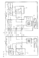
- FIG. 1 is an explanatory drawing for illustrating a structure example of a charging system according to Embodiment 1 of the present invention.
- FIG. 1 illustrates an example wherein a charging system of the present invention is applied to a configuration wherein power is fed from a feed device 2 such as a charging stand to a battery (an electric power storage device) 10 provided in a vehicle 1 such as an electric automobile or a plug-in hybrid automobile.
- a charging system according to the present invention is a system, which is to be mounted on the vehicle 1, pertaining to charging, and a communication system configured to transmit and receive a communication signal between the vehicle 1 and the feed device 2 is constructed by connecting the vehicle 1 according to the charging system of the present invention with the feed device 2.
- the vehicle 1 and the feed device 2 can be connected with each other by a charging cable 3.
- the charging cable 3 includes two feeder wires 31 and 32 to be used as electric power supply wires, a ground wire 33 which is a lead for grounding, and a control wire 34 configured to transmit a control signal such as a control pilot signal (CPLT) to be used for charge control.
- One end of the charging cable 3 is connected with a feed device 2 side, and a plug 30 provided at the other end side can be connected with a power receiving connector 11, which is placed as a vehicle-mounted feeding port that functions as a connection position at a vehicle 1 side.
- connection terminals 30a, 30b, 30c and 30d which are provided at end parts of the feeder wires 31 and 32, of the ground wire 33, and of the control wire 34 in the charging cable 3, come into contact with connection terminals 11 a, 11 b, 11c and 11 d provided in the power receiving connector 11, so that a circuit configuration illustrated in FIG. 1 is obtained.
- the feeder wires 31 and 32 are AC wires to which AC voltage is to be applied.
- the control wire 34 is a signal wire configured to transmit and receive a control signal such as a control pilot signal, and charge control is performed on the basis of a control pilot signal to be transmitted and received when the feed device 2 and a charge control device 13 are connected with each other.
- the ground wire 33 and the control wire 34 can be used as media configured to transmit information to be used for management such as vehicle authentication, charging management or accounting management, or various kinds of other information. That is, the vehicle 1 and the feed device 2 can perform communication by superposing and separating a communication signal for the ground wire 33 and the control wire 34.
- the feed device 2 is provided with an electric power supply unit 20 configured to supply AC electric power, a charge control unit 21 configured to perform communication pertaining to charge control, a communication unit 22 configured to transmit and receive a communication signal, and a superposition separation unit 23 interposed in the control wire 34 so as to superpose and separate a communication signal.
- an electric power supply unit 20 configured to supply AC electric power
- a charge control unit 21 configured to perform communication pertaining to charge control
- a communication unit 22 configured to transmit and receive a communication signal
- a superposition separation unit 23 interposed in the control wire 34 so as to superpose and separate a communication signal.
- the electric power supply unit 20 is connected with one end of each of the feeder wires 31 and 32 and with the ground wire 33.
- the charge control unit 21 is connected with one end of the control wire 34 and with the ground wire 33.
- wiring in the feed device 2 is hence an internal lead which functions as an extension line connected with the feeder wires 31 and 32, with the ground wire 33, and with the control wire 34 included in the charging cable 3 outside the feed device 2
- an extension line part placed as an internal lead is assumed in the following description to be included in the feeder wires 31 and 32, the ground wire 33 and the control wire 34 for convenience.
- the charge control unit 21 is a circuit at an output side compliant with an international standard pertaining to charge control, for example, and performs charge control in various states such as confirmation of connection or initiation of energization by transmitting and receiving a control signal such as a control pilot signal.
- the charge control unit 21 is provided with various kinds of elements such as a capacitor C1 and a resistance R1, and with various kinds of circuits such as an oscillation circuit.
- the capacitor C1 is disposed in such a manner of bridging the ground wire 33 and the control wire 34 and forms a part of transmission path for a communication signal.
- the superposition separation unit 23 is interposed in the control wire 34, and is constituted of a circuit such as a coupling transformer (a signal converter of electromagnetic induction type).
- the superposition separation unit 23 superposes various kinds of communication signals for the control wire 34, and separates various kinds of superposed communication signals. Communication by the communication unit 22 is achieved when the superposition separation unit 23 superposes various kinds of communication signals outputted from the communication unit 22 and inputs various kinds of separated communication signals to the communication unit 22.
- the vehicle 1 is provided with a charging device 12 configured to charge the battery 10, the charge control device 13 configured to perform communication pertaining to charge control, a communication device 14 configured to transmit and receive a communication signal, and a superposition separation element 15 configured to superpose and separate a communication signal for the control wire 34, in addition to the battery 10 and the power receiving connector 11.
- a charging device 12 configured to charge the battery 10
- the charge control device 13 configured to perform communication pertaining to charge control
- a communication device 14 configured to transmit and receive a communication signal
- a superposition separation element 15 configured to superpose and separate a communication signal for the control wire 34, in addition to the battery 10 and the power receiving connector 11.
- connection terminals 30a, 30b, 30c and 30d which are provided respectively at the other end of each of the feeder wires 31 and 32, at the other end of the ground wire 33, and at the other end of the control wire 34 included in the charging cable 3, are connected with the connection terminals 11 a, 11 b, 11c and 11 d provided in the power receiving connector 11.
- the power receiving connector 11 has a housing 110, which will be described later, as illustrated in FIG. 2 , and internal wirings 111, 112, 113 and 114 to be connected with the feeder wires 31 and 32, with the ground wire 33, and with the control wire 34 via the connection terminals 11 a, 11 b, 11c and 11 d are provided in the housing 110.
- the other end of each of the internal wirings 111 and 112 connected with the feeder wires 31 and 32 is connected with the charging device 12 via an AC wire placed inside the vehicle 1, and charging to the battery 10 is performed by the charging device 12.
- the other end of the internal wiring 113 connected with the ground wire 33 is connected via internal wiring in the vehicle 1 or via body earth with the charging device 12 and the charge control device 13, and further with the battery 10.
- each internal wiring 114 connected with the control wire 34 is connected with the charge control device 13 via an extension line placed as internal wiring in the vehicle 1. It is to be noted that each internal wiring, each AC wire and each extension line are assumed in the following description to be included in the feeder wires 31 and 32, the ground wire 33 and the control wire 34 for convenience when there is no particular need for division.
- the superposition separation element 15 is interposed in the internal wiring 114 to be connected with the control wire 34.
- a capacitor 16, for example, is disposed as path means which forms a communication path by bridging the internal wiring 113 to be connected with the ground wire 33 and the internal wiring 114 to be connected with the control wire 34.
- the capacitor 16 is connected at the charge control device 13 side with respect to a position where the control wire 34 is connected with the superposition separation element 15.
- a transmission path for communication signal which passes the connection terminal 11 c to be connected with the ground wire 33, the internal wiring 113, the capacitor 16, the internal wiring 114, the superposition separation element 15 to be interposed in the internal wiring 114, and the connection terminal 11d to be connected with the control wire 34, is formed in the power receiving connector 11.
- the capacitor 16 passes a signal of a frequency band to be used for a communication signal and interrupts a signal of a frequency band to be used for a control signal.
- a band of a frequency to be used for a communication signal a band of several tens kHz to several hundreds kHz, e.g. a band of 30 kHz to 450 kHz, is used as a band for low speed communication.
- a band of several MHz to several tens MHz e.g. a band of 2 MHz to 30 MHz, is used as a band for high speed communication.
- a control signal which is outputted from an oscillator of 1 kHz, becomes a signal at a frequency lower than that of a communication signal.
- the charge control device 13 is a circuit at an input side compliant with an international standard pertaining to charge control, for example, and is provided with various elements such as a capacitor C2, a resistance R2, and a diode Vd.
- the charge control device 13 performs charge control in various states such as confirmation of connection or initiation of communication by transmitting and receiving a control signal such as a control pilot signal when being able to communicate with the charge control unit 21 of the feed device 2.
- the communication device 14 is provided with a function to transmit and receive various kinds of communication signals to and from the feed device 2, and is connected with the superposition separation element 15 by a pair of communication lines.
- the superposition separation element 15 is a circuit such as a coupling transformer (a signal converter of electromagnetic induction type) which is provided with a primary coil 150 of which both ends are connected with the internal wiring 114 to be connected with the ground wire 34, and a secondary coil 151 to be coupled electromagnetically with the primary coil 150.
- a coupling transformer a signal converter of electromagnetic induction type
- the superposition separation element 15 superposes various kinds of communication signals for the control wire 34 via the internal wiring 114, and separates various kinds of superposed communication signals. Communication by the communication device 14 is achieved when the superposition separation element 15 superposes various kinds of communication signals outputted from the communication device 14 and inputs various kinds of separated communication signals to the communication device 14.
- a loop circuit configured to transmit a communication signal is formed with the superposition separation element 15, the ground wire 33, the control wire 34, the superposition separation unit 23, and other wirings, elements and circuits. This makes it possible to realize inband communication of superposing a communication signal for the ground wire 33 and the control wire 34 between the communication device 14 in the vehicle 1 and the communication unit 22 of the feed device 2.
- the power receiving connector 11 to be placed as a vehicle-mounted feeding port is formed by integrating the connection terminals 11 a, 11 b, 11c and 11d, the internal wirings 111, 112, 113 and 114, the superposition separation element 15, and the capacitor 16 with the housing 110.
- members required for communication such as inband communication, such as various kinds of wiring, elements and circuits described above, are to be integrated with the power receiving connector 11 as a replacement unit at the time of parts replacement, i.e., a replaceable unit.
- FIG. 2 is an outside drawing for illustrating an example of the power receiving connector 11 according to Embodiment 1 of the present invention.
- FIG. 2 illustrates a side face of the power receiving connector 11, and the housing 110 of the power receiving connector 11 illustrated in FIG. 2 has a form wherein two cylindrical bodies, which have a common center axis and have different radii and different heights, are coupled with each other, and a rectangular parallelepiped container of the superposition separation element 15 is further coupled therewith.
- the housing 110 is constituted of a member made of a material, such as metal or resin, selected properly in consideration of weight, size, durability, and various kinds of other factors such as electromagnetic wave shielding performance as necessary.
- FIG. 2 illustrates a state where a cover part provided at the housing 110 is open. The cover part is opened for the purpose of connecting the plug 30 at the time of charging, for example.
- a part of each of the internal wirings 111, 112, 113 and 114 is exposed from the housing 110, and a tip of each of the internal wirings 111, 112, 113 and 114 is provided with a terminal to be inserted into the vehicle 1.
- a twisted wire pair 140 to be connected with the communication device 14 extends from the superposition separation element 15, and a tip of the twisted wire pair 140 is provided with a terminal to be connected with the communication device 14. It is to be noted that a structure which uses the twisted wire pair 140 will be described later as Embodiment 3.
- connection terminals 11 a, 11 b, 11c and 11 d, the internal wirings 111, 112, 113 and 114, the superposition separation element 15, and the capacitor 16 are contained inside the housing 110.
- members thereof, such as various kinds of wirings, elements and circuits, are integrated as a replaceable unit, it is possible to perform operations such as replacement of the power receiving connector 11 easily by fixing the housing 110 to the vehicle 1 by a method such as screw clamping and connecting terminals provided at the respective wirings properly.
- design can be modified properly by providing a container of the superposition separation element 15 apart from the cylindrical bodies, for example, as long as it is possible to treat in an integrated manner.
- the power receiving connector 11 is formed by integrating the wirings, elements and circuits including the superposition separation element 15 having a coupling transformer and the capacitor 16 forming a path.
- the power receiving connector 11 By integrating various kinds of wirings, elements and circuits with the power receiving connector 11, it is possible to shorten a transmission path of a communication signal, and a communication signal is prevented from flowing into a harness (wiring) in the vehicle 1 more than necessary.
- This also makes a communication signal and various kinds of equipment at a communication side hardly influenced by an electromagnetic wave emitted from various kinds of equipment in the vehicle 1.
- the power receiving connector 11 can absorb a difference between power line communication and inband communication, and therefore it becomes possible to adapt the vehicle 1 to specification modification of communication without modifying design of the vehicle 1 itself.
- Embodiment 2 is a configuration wherein a low-pass filter is provided on the control wire in Embodiment 1. It is to be noted that reference signs similar to those of Embodiment 1 are attached to structures similar to those of Embodiment 1 in the following description so as to refer to Embodiment 1, and detailed description thereof will be omitted.
- FIG. 3 is an explanatory drawing for illustrating a structure example of a charging system according to Embodiment 2 of the present invention.
- a low-pass filter (LPF) 114b is interposed in internal wiring 114 of a vehicle 1 to be connected with a control wire 34 as separation means configured to separate a control signal and a communication signal from each other.
- the low-pass filter 114b is placed on the internal wiring 114 and between a connection position of the capacitor 16 and a charge control device 13.
- the low-pass filter 114b passes a signal of a band at a frequency lower than a predetermined frequency, e.g. a band to be used for a control signal, and interrupts a communication signal.
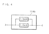
- FIG. 4 is a circuit diagram for illustrating a structure example of the low-pass filter 114b to be used in a charging system according to Embodiment 2 of the present invention.
- the low-pass filter 114b is constructed as a circuit wherein a coil having an inductance of 1.5 mH and a resistance of 1.0 k ⁇ are arranged in parallel as illustrated in FIG. 4 , for example, or an equivalent circuit thereof. It is to be noted that the low-pass filter 114b may be constituted of another circuit, as long as similar characteristics can be obtained. Moreover, the value of an element to be used for the low-pass filter is exemplary, and an element having another value may be used.
- a power receiving connector 11 to be placed as a vehicle-mounted feeding port is formed by integrating connection terminals 11 a, 11 b, 11c and 11 d, internal wirings 111, 112, 113 and 114, a superposition separation element 15, a capacitor 16, and the low-pass filter 114b with a housing 110.
- Embodiment 1 By providing the low-pass filter 114b so as to be integrated with the power receiving connector 11, leakage of a communication signal from the power receiving connector 11 is prevented, and therefore the effectiveness of the effect of decreasing mutual influence by an electromagnetic wave illustrated in Embodiment 1 can be further improved. That is, noise emitted from one of other equipment in the vehicle 1 and a transmission path of a communication signal is prevented from influencing the other, and this can prevent occurrence of abnormality such as voltage misreading of a control signal, for example.
- Embodiment 3 is a configuration wherein, in Embodiment 1, path means is removed from the power receiving connector and only the superposition separation element is integrated to the power receiving connector. It is to be noted that reference signs similar to those of Embodiment 1 are attached to structures similar to those of Embodiment 1 in the following description so as to refer to Embodiment 1, and detailed description thereof will be omitted.
- FIG. 5 is an explanatory drawing for illustrating a structure example of a charging system according to Embodiment 3 of the present invention.
- the power receiving connector 11 is formed by integrating the connection terminals 11 a, 11 b, 11c and 11 d, the internal wirings 111, 112, 113 and 114, and the superposition separation element 15 with the housing 110. That is, the structure example illustrated in FIG. 1 is changed into a structure wherein the capacitor 16 used as path means is not integrated and is separated.
- FIG.6 is an explanatory drawing for illustrating another structure example of a charging system according to Embodiment 3 of the present invention.
- the structure example of Embodiment 3 illustrated in FIG.6 is a structure wherein the capacitor 16 is removed from the structure illustrated in FIG.5 . Even in a case where the capacitor 16 is removed, the capacitor C2 in the charge control device 13 functions as path means which forms a communication path by bridging the internal wiring 113 to be connected with a ground wire 33 and the internal wiring 114 to be connected with a control wire 34.
- Embodiment 3 can be developed into various structures.
- Embodiment 4 is a configuration wherein the receiving connector and the communication device in Embodiment 1, 2 or 3 are connected with each other by a twisted wire pair. It is to be noted that reference signs similar to those of Embodiment 1, 2 or 3 are attached to structures similar to those of Embodiment 1,2 or 3 so as to refer to Embodiment 1, 2 or 3, and description thereof will be omitted.
- a charging system according to Embodiment 4 is a configuration wherein the superposition separation element 15 and the communication device 14 integrated with the power receiving connector 11 in the structure example illustrated in Embodiment 1, 2 or 3 are connected with each other by a twisted wire pair, and structures other than the structure between the superposition separation element 15 and the communication device 14 are not especially modified. Accordingly, regarding a structure example of the entire charging system, Embodiment 1, 2 or 3 is to be referred to, and description thereof will be omitted.
- FIG. 7 is an explanatory drawing for illustrating an example of the structure between the superposition separation element 15 and the communication device 14 of a charging system according to Embodiment 4 of the present invention.
- Wiring between the superposition separation element 15 and the communication device 14 is constituted of a twisted wire pair 140.
- the twisted wire pair 140 having a length of 2 to 4 m, for example, is provided in the vehicle 1.
- the communication device 14 is provided with a choke coil 141 to be connected with the twisted wire pair 140.
- the twisted wire pair 140 By using the twisted wire pair 140, it is possible to reduce the influence of noise on a communication signal. Moreover, it is possible to remove noise, which flows into the communication device 14 in a common mode state through the twisted wire pair 140, from the choke coil 141 which functions as a common mode choke coil.
- a superposition separation element 15 is interposed in internal wiring to be connected with a ground wire or is interposed in internal wiring both at a control wire side and at a ground wire side.
- the present invention is not limited to the embodiments having a configuration wherein a low-pass filter is not provided at a feed device side, and a low-pass filter may be provided at the feed device side. Moreover, similar effects can also be obtained at the feed device side, by putting a signal separation unit such as a branch part, a low-pass filter or a capacitor as close to a vehicle side in a feed device as possible.
- the present invention is not limited to the embodiments having a configuration wherein both a feed device side and a vehicle side have similar structures in which a superposition separation element or the like is interposed, either one of feed device side and the vehicle side may have a structure in which a branch line is arranged in a control wire or the like and a superposition separation element or the like is connected with it.
Abstract
Description
- The present application relates to a power receiving connector, which is to be connected with a charging cable extending from a feed device for power feeding from the feed device to an electric power storage device mounted on a vehicle, and to a charging system and a communication system, which uses the power receiving connector.
- In recent years, an electric automobile and a hybrid automobile, which have devices such as a motor and a battery mounted thereon and run by driving the motor with electric power stored in the battery, have begun to spread. Regarding an electric automobile, charging to a battery is achieved by power feeding from an outside feed device. Even regarding a hybrid automobile, a plug-in hybrid automobile, in which charging from an outside feed device to a battery can be performed, has come into practical use. It is to be noted that the outside feed device is a feed device, which is located in facilities such as an ordinary house or a commercial power feeding station. For power feeding from a feed device to a vehicle, a plug at a tip of a charging cable connected with the feed device is connected with a feeding port, which is placed in a vehicle as a power receiving connector. In addition, power feeding from the feed device via a feeder wire, which is included in the charging cable, to the vehicle is performed and the battery is charged.
- It is to be noted that the charging cable includes not only the feeder wire but also other wiring such as a ground wire and a control wire. A control wire is a wiring, which is to be used for transmission of a control signal such as a control pilot signal to be used for power feeding control of an electric power storage device. By transmitting and receiving a control signal between a feed device and a vehicle via the control wire, various states such as a connection state of a charging cable, a state of the possibility of charging, and a state of charging are detected, and charge control corresponding to detected states is performed.
- Furthermore, for practical application of an automobile such as an electric automobile or a hybrid automobile which requires power feeding from outside, demanded is a communication function to transmit and receive information, which is to be used for charge control, and communication information, which is to be used for management of charge amount or accounting or the like, between a vehicle and a feed device.
- Therefore, standardization of communication such as inband communication for superimposing a communication signal on a control signal and transmitting and receiving an obtained signal between a vehicle and a feed device is being promoted (see Non-Patent
Document 1, for example). -
FIG. 8 is an explanatory drawing for illustrating a structure example of a system, standardization of which is being promoted. Denoted at 1000 inFIG. 8 is a vehicle, and thevehicle 1000 is connected with acharging cable 3000 for power feeding from afeed device 2000. Thecharging cable 3000 includes twofeeder wires 3001 and 3002 to be used as electric power supply wires, aground wire 3003 which is a lead for grounding, and acontrol wire 3004 configured to transmit a control signal such as a control pilot signal (CPLT) to be used for charge control. - One end of the
charging cable 3000 is connected with afeed device 2000 side, and power feeding becomes possible by connecting aplug 3005, which is provided at the other end side, with apower receiving connector 1001, which is placed at a feeding port at avehicle 1000 side as a connection part. - The
feed device 2000 is provided with an electricpower supply unit 2001 configured to supply AC electric power, acharge control unit 2002 configured to perform communication pertaining to charge control, acommunication unit 2003 configured to transmit and receive a communication signal, and asuperposition separation unit 2004 interposed in thecontrol wire 3004 so as to superpose and separate the communication signal. - In addition, the
superposition separation unit 2004 superposes various kinds of communication signals for thecontrol wire 3004, and separates various kinds of superposed communication signals. Communication by thecommunication unit 2003 is achieved when thesuperposition separation unit 2004 superposes various kinds of communication signals outputted from thecommunication unit 2003 and inputs various kinds of separated communication signals to thecommunication unit 2003. - The
vehicle 1000 is provided with thepower receiving connector 1001, abattery 1002, acharging device 1003 configured to charge thebattery 1002, acharge control device 1004 configured to perform communication pertaining to charge control, acommunication device 1005 configured to transmit and receive a communication signal, and asuperposition separation element 1006 interposed in thecontrol wire 3004 so as to superpose and separate a communication signal. - In addition, the
superposition separation element 1006 superposes various kinds of communication signals for thecontrol wire 3004, and separates various kinds of superposed communication signals. Communication by thecommunication device 1005 is achieved when thesuperposition separation element 1006 superposes various kinds of communication signals outputted from thecommunication device 1005 and inputs various kinds of separated communication signals to thecommunication device 1005. - [Non-Patent Document 1] "SURFACE VEHICLE RECOMMENDED PRACTICE", J1772 JAN2010, Society of Automotive Engineers, Inc., October 1996
- A system having the structure illustrated in
FIG. 8 , however, has a problem that various noise made by various kinds of equipment in a vehicle affects a communication signal to be transmitted through wiring in the vehicle. - Moreover, an example of a method of transmitting a communication signal other than inband communication described above is power line communication. Such a communication method, however, is still at the investigation stage for formulation and employment of a standard, and therefore different communication methods may possibly be employed in countries or regions. This causes a problem that large man-hour of operations is required for replacement of members such as a power receiving connector so as to adapt a vehicle corresponding to power line communication to inband communication, or for the opposite case.
- The present invention has been made in view of such a situation, and the main object thereof is to provide a power receiving connector, a charging system and a communication system wherein various kinds of elements, circuits and wirings required for communication such as inband communication are provided in a power receiving connecter, so that the influence of noise on a communication signal can be reduced.
- Moreover, another object of the present invention is to provide a power receiving connector, a charging system and a communication system configured so that the man-hour of replacement operations for conversion to communication of a different form such as power line communication or inband communication can be decreased.
- A power receiving connector according to the present invention is a power receiving connector, which can be placed in a vehicle and can be connected with a feeder wire to be used for power feeding, with a ground wire, and with a control wire configured to transmit a control signal to be used for power feeding control, comprising: a plurality of connection terminals to be connected with the feeder wire, the ground wire and the control wire; a plurality of internal wirings to be connected with the feeder wire, the ground wire and the control wire via the connection terminals; and a superposition separation element, which is interposed in at least one of the internal wiring to be connected with the ground wire and the internal wiring to be connected with the control wire, configured to superpose and separate a communication signal, which is different from the control signal, for the internal wiring.
- A power receiving connector according to the present invention is characterized by further comprising a housing configured to incorporate the connection terminals and the superposition separation element.
- A power receiving connector according to the present invention is characterized by further comprising path means which passes the connection terminal to be connected with the ground wire, the superposition separation element, and the connection terminal to be connected with the control wire, and which bridges the internal wiring to be connected with the ground wire and the internal wiring to be connected with the control wire in order to form a communication path for the communication signal.
- A power receiving connector according to the present invention is characterized in that the path means is a capacitor configured to pass the communication signal and interrupt the control signal.
- A power receiving connector according to the present invention is characterized by further comprising separation means which is interposed at a vehicle side of the ground wire and /or the control wire with respect to the connection position of the path means, and which separates the control signal and the communication signal by passing a signal of a band related to the control signal.
- A power receiving connector according to the present invention is characterized in that the superposition separation element has: a primary coil to be connected with the internal wiring in which the superposition separation element is interposed; and a secondary coil to be coupled electromagnetically with the primary coil, and the secondary coil can be connected with a communication device configured to transmit and receive the communication signal via the control wire and the ground wire.
- A charging system according to the present invention is a charging system configured to be mounted to a vehicle which has an electric power storage device and can be connected with an outside feed device that feeds power to the electric power storage device through a charging cable that includes a feeder wire to be used for power feeding, a ground wire and a control wire configured to transmit a control signal to be used for power feeding control of the electric power storage device, characterized by comprising: a power receiving connecter according to Claim 6 which can be connected with a charging cable extending from the feed device; and a communication device configured to transmit and receive a communication signal to and from the feed device via the power receiving connector, and characterized in that the communication device is connected with a secondary coil of the superposition separation element the power receiving connecter comprises.
- A charging system according to the present invention is characterized in that the power receiving connector and the communication device are connected with each other by a twisted wire pair, and the communication device further comprises a choke coil to be connected with the twisted wire pair.
- A communication system according to the present invention is a communication system for connecting a feed device with a vehicle, which is provided with an electric power storage device to be fed from the feed device, by a charging cable, which includes a feeder wire to be used for power feeding, a ground wire and a control wire configured to transmit a control signal to be used for power feeding control of the electric power storage device, and for transmitting and receiving a communication signal, which is different from the control signal, using the control wire as a medium, characterized in that the vehicle comprises: a power receiving connecter according to Claim 6 to be connected with a charging cable extending from the feed device; and a communication device configured to transmit and receive a communication signal to and from the feed device via the power receiving connector, and the communication device is connected with a secondary coil of the superposition separation element the power receiving connecter comprises.
- With the present invention, it is possible to shorten internal wiring in a section where a communication signal is superposed.
- Moreover, with the present invention, it is possible to incorporate members pertaining to inband communication in a housing and to handle the members integrally.
- Moreover, with the present invention, it is possible to prevent leakage of a communication signal from a power receiving connector, by integrating path means further separation means to a housing.
- Moreover, with the present invention, the influence of noise on a communication signal is reduced by using a twisted wire pair. Furthermore, by using the choke coil which functions as a common mode choke coil, it is possible to decrease common mode noise.
- In a power receiving connector, a charging system and a communication system according to the present invention, internal wiring in a section where a communication signal is superposed is shortened by providing a superposition separation element, and various kinds of other elements, circuits and wirings, which are required for communication such as inband communication, in a power receiving connector. This exhibits excellent effects such that a communication signal is hardly influenced by an electromagnetic wave made by equipment in a vehicle and that it is possible to prevent an electromagnetic wave generated by transmission of a communication signal from influencing other equipment in a vehicle.
- Moreover, since members pertaining to inband communication can be handled integrally, exhibited are excellent effects such that operations for replacement of members are facilitated in a case where a vehicle corresponding to power line communication is to be changed into a vehicle corresponding to inband communication, for example.
- Also, the present invention exhibits excellent effects such that the influence of an electromagnetic wave can be further decreased owing to preventing leakage of a communication signal from a power receiving connector by disposing path means further separation means.
- Furthermore, the present invention exhibits excellent effects such that the influence of noise on a communication signal can be reduced by using a twisted wire pair and a choke coil.
-
-
FIG. 1 is an explanatory drawing for illustrating a structure example of a charging system according toEmbodiment 1 of the present invention. -
FIG. 2 is an outside drawing for illustrating an example of a power receiving connector according toEmbodiment 1 of the present invention. -
FIG. 3 is an explanatory drawing for illustrating a structure example of a charging system according toEmbodiment 2 of the present invention. -
FIG. 4 is a circuit diagram for illustrating a structure example of a low-pass filter to be used in a charging system according toEmbodiment 2 of the present invention. -
FIG. 5 is an explanatory drawing for illustrating a structure example of a charging system according toEmbodiment 3 of the present invention. -
FIG. 6 is an explanatory drawing for illustrating another structure example of a charging system according toEmbodiment 3 of the present invention. -
FIG. 7 is an explanatory drawing for illustrating an example of the structure between a superposition separation element and a communication device of a charging system according to Embodiment 4 of the present invention. -
FIG. 8 is an explanatory drawing for illustrating a structure example of a system, standardization of which is being promoted. - The following description will explain the present invention in detail with reference to the drawings for illustrating embodiments thereof.
-
FIG. 1 is an explanatory drawing for illustrating a structure example of a charging system according toEmbodiment 1 of the present invention.FIG. 1 illustrates an example wherein a charging system of the present invention is applied to a configuration wherein power is fed from afeed device 2 such as a charging stand to a battery (an electric power storage device) 10 provided in avehicle 1 such as an electric automobile or a plug-in hybrid automobile. A charging system according to the present invention is a system, which is to be mounted on thevehicle 1, pertaining to charging, and a communication system configured to transmit and receive a communication signal between thevehicle 1 and thefeed device 2 is constructed by connecting thevehicle 1 according to the charging system of the present invention with thefeed device 2. - The
vehicle 1 and thefeed device 2 can be connected with each other by a chargingcable 3. The chargingcable 3 includes twofeeder wires ground wire 33 which is a lead for grounding, and acontrol wire 34 configured to transmit a control signal such as a control pilot signal (CPLT) to be used for charge control. One end of the chargingcable 3 is connected with afeed device 2 side, and aplug 30 provided at the other end side can be connected with apower receiving connector 11, which is placed as a vehicle-mounted feeding port that functions as a connection position at avehicle 1 side. By connecting theplug 30 at the other end of the chargingcable 3 with thepower receiving connector 11,connection terminals feeder wires ground wire 33, and of thecontrol wire 34 in the chargingcable 3, come into contact withconnection terminals power receiving connector 11, so that a circuit configuration illustrated inFIG. 1 is obtained. - The
feeder wires control wire 34 is a signal wire configured to transmit and receive a control signal such as a control pilot signal, and charge control is performed on the basis of a control pilot signal to be transmitted and received when thefeed device 2 and acharge control device 13 are connected with each other. Moreover, theground wire 33 and thecontrol wire 34 can be used as media configured to transmit information to be used for management such as vehicle authentication, charging management or accounting management, or various kinds of other information. That is, thevehicle 1 and thefeed device 2 can perform communication by superposing and separating a communication signal for theground wire 33 and thecontrol wire 34. - The
feed device 2 is provided with an electricpower supply unit 20 configured to supply AC electric power, acharge control unit 21 configured to perform communication pertaining to charge control, acommunication unit 22 configured to transmit and receive a communication signal, and asuperposition separation unit 23 interposed in thecontrol wire 34 so as to superpose and separate a communication signal. - The electric
power supply unit 20 is connected with one end of each of thefeeder wires ground wire 33. Thecharge control unit 21 is connected with one end of thecontrol wire 34 and with theground wire 33. Although wiring in thefeed device 2 is hence an internal lead which functions as an extension line connected with thefeeder wires ground wire 33, and with thecontrol wire 34 included in the chargingcable 3 outside thefeed device 2, an extension line part placed as an internal lead is assumed in the following description to be included in thefeeder wires ground wire 33 and thecontrol wire 34 for convenience. - The
charge control unit 21 is a circuit at an output side compliant with an international standard pertaining to charge control, for example, and performs charge control in various states such as confirmation of connection or initiation of energization by transmitting and receiving a control signal such as a control pilot signal. - The
charge control unit 21 is provided with various kinds of elements such as a capacitor C1 and a resistance R1, and with various kinds of circuits such as an oscillation circuit. The capacitor C1 is disposed in such a manner of bridging theground wire 33 and thecontrol wire 34 and forms a part of transmission path for a communication signal. - The
superposition separation unit 23 is interposed in thecontrol wire 34, and is constituted of a circuit such as a coupling transformer (a signal converter of electromagnetic induction type). - The
superposition separation unit 23 superposes various kinds of communication signals for thecontrol wire 34, and separates various kinds of superposed communication signals. Communication by thecommunication unit 22 is achieved when thesuperposition separation unit 23 superposes various kinds of communication signals outputted from thecommunication unit 22 and inputs various kinds of separated communication signals to thecommunication unit 22. - The
vehicle 1 is provided with a chargingdevice 12 configured to charge thebattery 10, thecharge control device 13 configured to perform communication pertaining to charge control, acommunication device 14 configured to transmit and receive a communication signal, and asuperposition separation element 15 configured to superpose and separate a communication signal for thecontrol wire 34, in addition to thebattery 10 and thepower receiving connector 11. - By connecting the
plug 30 of the chargingcable 3 with thepower receiving connector 11 of thevehicle 1, theconnection terminals feeder wires ground wire 33, and at the other end of thecontrol wire 34 included in the chargingcable 3, are connected with theconnection terminals power receiving connector 11. - The
power receiving connector 11 has ahousing 110, which will be described later, as illustrated inFIG. 2 , andinternal wirings feeder wires ground wire 33, and with thecontrol wire 34 via theconnection terminals housing 110. The other end of each of theinternal wirings feeder wires device 12 via an AC wire placed inside thevehicle 1, and charging to thebattery 10 is performed by the chargingdevice 12. The other end of theinternal wiring 113 connected with theground wire 33 is connected via internal wiring in thevehicle 1 or via body earth with the chargingdevice 12 and thecharge control device 13, and further with thebattery 10. The other end of theinternal wiring 114 connected with thecontrol wire 34 is connected with thecharge control device 13 via an extension line placed as internal wiring in thevehicle 1. It is to be noted that each internal wiring, each AC wire and each extension line are assumed in the following description to be included in thefeeder wires ground wire 33 and thecontrol wire 34 for convenience when there is no particular need for division. - The
superposition separation element 15 is interposed in theinternal wiring 114 to be connected with thecontrol wire 34. - A
capacitor 16, for example, is disposed as path means which forms a communication path by bridging theinternal wiring 113 to be connected with theground wire 33 and theinternal wiring 114 to be connected with thecontrol wire 34. Thecapacitor 16 is connected at thecharge control device 13 side with respect to a position where thecontrol wire 34 is connected with thesuperposition separation element 15. Thus, a transmission path for communication signal, which passes the connection terminal 11 c to be connected with theground wire 33, theinternal wiring 113, thecapacitor 16, theinternal wiring 114, thesuperposition separation element 15 to be interposed in theinternal wiring 114, and theconnection terminal 11d to be connected with thecontrol wire 34, is formed in thepower receiving connector 11. By using thecapacitor 16 as path means, thecapacitor 16 passes a signal of a frequency band to be used for a communication signal and interrupts a signal of a frequency band to be used for a control signal. - Regarding a band of a frequency to be used for a communication signal, a band of several tens kHz to several hundreds kHz, e.g. a band of 30 kHz to 450 kHz, is used as a band for low speed communication. Moreover, a band of several MHz to several tens MHz, e.g. a band of 2 MHz to 30 MHz, is used as a band for high speed communication. It is to be noted that a control signal, which is outputted from an oscillator of 1 kHz, becomes a signal at a frequency lower than that of a communication signal.
- The
charge control device 13 is a circuit at an input side compliant with an international standard pertaining to charge control, for example, and is provided with various elements such as a capacitor C2, a resistance R2, and a diode Vd. Thecharge control device 13 performs charge control in various states such as confirmation of connection or initiation of communication by transmitting and receiving a control signal such as a control pilot signal when being able to communicate with thecharge control unit 21 of thefeed device 2. - The
communication device 14 is provided with a function to transmit and receive various kinds of communication signals to and from thefeed device 2, and is connected with thesuperposition separation element 15 by a pair of communication lines. - The
superposition separation element 15 is a circuit such as a coupling transformer (a signal converter of electromagnetic induction type) which is provided with aprimary coil 150 of which both ends are connected with theinternal wiring 114 to be connected with theground wire 34, and asecondary coil 151 to be coupled electromagnetically with theprimary coil 150. - The
superposition separation element 15 superposes various kinds of communication signals for thecontrol wire 34 via theinternal wiring 114, and separates various kinds of superposed communication signals. Communication by thecommunication device 14 is achieved when thesuperposition separation element 15 superposes various kinds of communication signals outputted from thecommunication device 14 and inputs various kinds of separated communication signals to thecommunication device 14. - That is, a loop circuit configured to transmit a communication signal is formed with the
superposition separation element 15, theground wire 33, thecontrol wire 34, thesuperposition separation unit 23, and other wirings, elements and circuits. This makes it possible to realize inband communication of superposing a communication signal for theground wire 33 and thecontrol wire 34 between thecommunication device 14 in thevehicle 1 and thecommunication unit 22 of thefeed device 2. - In a charging system according to
Embodiment 1, thepower receiving connector 11 to be placed as a vehicle-mounted feeding port is formed by integrating theconnection terminals internal wirings superposition separation element 15, and thecapacitor 16 with thehousing 110. - That is, in the present invention, members required for communication such as inband communication, such as various kinds of wiring, elements and circuits described above, are to be integrated with the
power receiving connector 11 as a replacement unit at the time of parts replacement, i.e., a replaceable unit. -
FIG. 2 is an outside drawing for illustrating an example of thepower receiving connector 11 according toEmbodiment 1 of the present invention.FIG. 2 illustrates a side face of thepower receiving connector 11, and thehousing 110 of thepower receiving connector 11 illustrated inFIG. 2 has a form wherein two cylindrical bodies, which have a common center axis and have different radii and different heights, are coupled with each other, and a rectangular parallelepiped container of thesuperposition separation element 15 is further coupled therewith. Thehousing 110 is constituted of a member made of a material, such as metal or resin, selected properly in consideration of weight, size, durability, and various kinds of other factors such as electromagnetic wave shielding performance as necessary. It is to be noted thatFIG. 2 illustrates a state where a cover part provided at thehousing 110 is open. The cover part is opened for the purpose of connecting theplug 30 at the time of charging, for example. - A part of each of the
internal wirings housing 110, and a tip of each of theinternal wirings vehicle 1. Moreover, atwisted wire pair 140 to be connected with thecommunication device 14 extends from thesuperposition separation element 15, and a tip of the twistedwire pair 140 is provided with a terminal to be connected with thecommunication device 14. It is to be noted that a structure which uses thetwisted wire pair 140 will be described later asEmbodiment 3. - As described above, all or a part of the
connection terminals internal wirings superposition separation element 15, and thecapacitor 16 are contained inside thehousing 110. Moreover, since members thereof, such as various kinds of wirings, elements and circuits, are integrated as a replaceable unit, it is possible to perform operations such as replacement of thepower receiving connector 11 easily by fixing thehousing 110 to thevehicle 1 by a method such as screw clamping and connecting terminals provided at the respective wirings properly. It is to be noted that design can be modified properly by providing a container of thesuperposition separation element 15 apart from the cylindrical bodies, for example, as long as it is possible to treat in an integrated manner. - As described above, the
power receiving connector 11 according toEmbodiment 1 of the present invention is formed by integrating the wirings, elements and circuits including thesuperposition separation element 15 having a coupling transformer and thecapacitor 16 forming a path. By integrating various kinds of wirings, elements and circuits with thepower receiving connector 11, it is possible to shorten a transmission path of a communication signal, and a communication signal is prevented from flowing into a harness (wiring) in thevehicle 1 more than necessary. - This decreases the risk of abnormality such as malfunction of various kinds of equipment in the
vehicle 1 or a communication failure due to the influence of an electromagnetic wave emitted from a communication signal. This also makes a communication signal and various kinds of equipment at a communication side hardly influenced by an electromagnetic wave emitted from various kinds of equipment in thevehicle 1. - Furthermore, by integrating the wirings, elements and circuits with the
power receiving connector 11 to be placed as a vehicle-mounted feeding port, it is possible to make thevehicle 1 having specifications corresponding to power line communication have specifications corresponding to inband communication only by replacing thepower receiving connector 11. Accordingly, thepower receiving connector 11 can absorb a difference between power line communication and inband communication, and therefore it becomes possible to adapt thevehicle 1 to specification modification of communication without modifying design of thevehicle 1 itself. -
Embodiment 2 is a configuration wherein a low-pass filter is provided on the control wire inEmbodiment 1. It is to be noted that reference signs similar to those ofEmbodiment 1 are attached to structures similar to those ofEmbodiment 1 in the following description so as to refer toEmbodiment 1, and detailed description thereof will be omitted. -
FIG. 3 is an explanatory drawing for illustrating a structure example of a charging system according toEmbodiment 2 of the present invention. InEmbodiment 2, a low-pass filter (LPF) 114b is interposed ininternal wiring 114 of avehicle 1 to be connected with acontrol wire 34 as separation means configured to separate a control signal and a communication signal from each other. The low-pass filter 114b is placed on theinternal wiring 114 and between a connection position of thecapacitor 16 and acharge control device 13. The low-pass filter 114b passes a signal of a band at a frequency lower than a predetermined frequency, e.g. a band to be used for a control signal, and interrupts a communication signal. -
FIG. 4 is a circuit diagram for illustrating a structure example of the low-pass filter 114b to be used in a charging system according toEmbodiment 2 of the present invention. The low-pass filter 114b is constructed as a circuit wherein a coil having an inductance of 1.5 mH and a resistance of 1.0 kΩ are arranged in parallel as illustrated inFIG. 4 , for example, or an equivalent circuit thereof. It is to be noted that the low-pass filter 114b may be constituted of another circuit, as long as similar characteristics can be obtained. Moreover, the value of an element to be used for the low-pass filter is exemplary, and an element having another value may be used. - In a charging system according to
Embodiment 2 of the present invention, apower receiving connector 11 to be placed as a vehicle-mounted feeding port is formed by integratingconnection terminals internal wirings superposition separation element 15, acapacitor 16, and the low-pass filter 114b with ahousing 110. - Since various kinds of wirings, elements and circuits are also integrated with the
housing 110 of thepower receiving connector 11 inEmbodiment 2 of the present invention, an example of the exterior thereof is similar to that of thepower receiving connector 11 according toEmbodiment 1 illustrated usingFIG. 2 . - By providing the low-
pass filter 114b so as to be integrated with thepower receiving connector 11, leakage of a communication signal from thepower receiving connector 11 is prevented, and therefore the effectiveness of the effect of decreasing mutual influence by an electromagnetic wave illustrated inEmbodiment 1 can be further improved. That is, noise emitted from one of other equipment in thevehicle 1 and a transmission path of a communication signal is prevented from influencing the other, and this can prevent occurrence of abnormality such as voltage misreading of a control signal, for example. -
Embodiment 3 is a configuration wherein, inEmbodiment 1, path means is removed from the power receiving connector and only the superposition separation element is integrated to the power receiving connector. It is to be noted that reference signs similar to those ofEmbodiment 1 are attached to structures similar to those ofEmbodiment 1 in the following description so as to refer toEmbodiment 1, and detailed description thereof will be omitted. -
FIG. 5 is an explanatory drawing for illustrating a structure example of a charging system according toEmbodiment 3 of the present invention. In the structure example ofEmbodiment 3 illustrated inFIG. 8 , thepower receiving connector 11 is formed by integrating theconnection terminals internal wirings superposition separation element 15 with thehousing 110. That is, the structure example illustrated inFIG. 1 is changed into a structure wherein thecapacitor 16 used as path means is not integrated and is separated. - In
Embodiment 3, without disposing thecapacitor 16, a capacitor C2 in acharge control device 13 may be substituted.FIG.6 is an explanatory drawing for illustrating another structure example of a charging system according toEmbodiment 3 of the present invention. The structure example ofEmbodiment 3 illustrated inFIG.6 is a structure wherein thecapacitor 16 is removed from the structure illustrated inFIG.5 . Even in a case where thecapacitor 16 is removed, the capacitor C2 in thecharge control device 13 functions as path means which forms a communication path by bridging theinternal wiring 113 to be connected with aground wire 33 and theinternal wiring 114 to be connected with acontrol wire 34. - As described above,
Embodiment 3 can be developed into various structures. - Embodiment 4 is a configuration wherein the receiving connector and the communication device in
Embodiment Embodiment Embodiment Embodiment - A charging system according to Embodiment 4 is a configuration wherein the
superposition separation element 15 and thecommunication device 14 integrated with thepower receiving connector 11 in the structure example illustrated inEmbodiment superposition separation element 15 and thecommunication device 14 are not especially modified. Accordingly, regarding a structure example of the entire charging system,Embodiment -
FIG. 7 is an explanatory drawing for illustrating an example of the structure between thesuperposition separation element 15 and thecommunication device 14 of a charging system according to Embodiment 4 of the present invention. Wiring between thesuperposition separation element 15 and thecommunication device 14 is constituted of atwisted wire pair 140. Thetwisted wire pair 140 having a length of 2 to 4 m, for example, is provided in thevehicle 1. Moreover, thecommunication device 14 is provided with achoke coil 141 to be connected with thetwisted wire pair 140. - By using the twisted
wire pair 140, it is possible to reduce the influence of noise on a communication signal. Moreover, it is possible to remove noise, which flows into thecommunication device 14 in a common mode state through thetwisted wire pair 140, from thechoke coil 141 which functions as a common mode choke coil. - The embodiments disclose only a part of innumerable examples of the present invention, and design can be modified properly in consideration of various factors such as objects, applications and specifications. For example, instead of the structure examples described above, it is possible to develop various configurations such that a
superposition separation element 15 is interposed in internal wiring to be connected with a ground wire or is interposed in internal wiring both at a control wire side and at a ground wire side. - Moreover, the present invention is not limited to the embodiments having a configuration wherein a low-pass filter is not provided at a feed device side, and a low-pass filter may be provided at the feed device side. Moreover, similar effects can also be obtained at the feed device side, by putting a signal separation unit such as a branch part, a low-pass filter or a capacitor as close to a vehicle side in a feed device as possible.
- Furthermore, the present invention is not limited to the embodiments having a configuration wherein both a feed device side and a vehicle side have similar structures in which a superposition separation element or the like is interposed, either one of feed device side and the vehicle side may have a structure in which a branch line is arranged in a control wire or the like and a superposition separation element or the like is connected with it.
-
- 1
- Vehicle
- 10
- Battery (Electric Power Storage Device)
- 11
- Power Receiving Connector
- 11a, 11b, 11c, 11d
- Connection Terminal
- 110
- Housing
- 111, 112, 113, 114
- Internal Wiring
- 12
- Charging Device
- 13
- Charge Control Device
- 14
- Communication Device
- 140
- Twisted Wire Pair
- 141
- Choke Coil
- 15
- Superposition Separation Element
- 150
- Primary Coil
- 151
- Secondary Coil
- 16
- Capacitor (Path Means)
- 2
- Feed Device
- 20
- Electric Power Supply Unit
- 21
- Charge Control Unit
- 22
- Communication Unit
- 23
- Superposition Separation Unit
- 3
- Charging Cable
- 30
- Plug
- 30a, 30b, 30c, 30d
- Connection Terminal
- 31, 32
- Feeder Wire
- 33
- Ground Wire
- 34
- Control Wire
Claims (9)
- A power receiving connector, which can be placed in a vehicle and can be connected with a feeder wire to be used for power feeding, with a ground wire, and with a control wire configured to transmit a control signal to be used for power feeding control, comprising:a plurality of connection terminals to be connected with the feeder wire, the ground wire and the control wire;a plurality of internal wirings to be connected with the feeder wire, the ground wire and the control wire via the connection terminals; anda superposition separation element, which is interposed in at least one of the internal wiring to be connected with the ground wire and the internal wiring to be connected with the control wire, configured to superpose and separate a communication signal, which is different from the control signal, for the internal wiring.
- The power receiving connector according to Claim 1, further comprising a housing configured to incorporate the connection terminals and the superposition separation element.
- The power receiving connector according to Claim 1 or 2, further comprising path means which passes the connection terminal to be connected with the ground wire, the superposition separation element, and the connection terminal to be connected with the control wire, and which bridges the internal wiring to be connected with the ground wire and the internal wiring to be connected with the control wire in order to form a communication path for the communication signal.
- The power receiving connector according to Claim 3, wherein the path means is a capacitor configured to pass the communication signal and interrupt the control signal.
- The power receiving connector according to Claim 3 or 4, further comprising separation means which is interposed at a vehicle side of the ground wire and /or the control wire with respect to the connection position of the path means, and which separates the control signal and the communication signal by passing a signal of a band related to the control signal.
- The power receiving connector according to any one of Claims 1 to 5, wherein
the superposition separation element has:a primary coil to be connected with the internal wiring in which the superposition separation element is interposed; anda secondary coil to be coupled electromagnetically with the primary coil, andthe secondary coil can be connected with a communication device configured to transmit and receive the communication signal via the control wire and the ground wire. - A charging system configured to be mounted to a vehicle which has an electric power storage device and can be connected with an outside feed device that feeds power to the electric power storage device through a charging cable that includes a feeder wire to be used for power feeding, a ground wire and a control wire configured to transmit a control signal to be used for power feeding control of the electric power storage device, comprising:a power receiving connecter according to Claim 6 which can be connected with a charging cable extending from the feed device; anda communication device configured to transmit and receive a communication signal to and from the feed device via the power receiving connector, andwherein the communication device is connected with a secondary coil of the superposition separation element the power receiving connecter comprises.
- The charging system according to Claim 7, wherein
the power receiving connector and the communication device are connected with each other by a twisted wire pair, and
the communication device further comprises a choke coil to be connected with the twisted wire pair. - A communication system for connecting a feed device with a vehicle, which is provided with an electric power storage device to be fed from the feed device, by a charging cable, which includes a feeder wire to be used for power feeding, a ground wire and a control wire configured to transmit a control signal to be used for power feeding control of the electric power storage device, and for transmitting and receiving a communication signal, which is different from the control signal, using the control wire as a medium, wherein
the vehicle comprises:a power receiving connecter according to Claim 6 to be connected with a charging cable extending from the feed device; anda communication device configured to transmit and receive a communication signal to and from the feed device via the power receiving connector, andthe communication device is connected with a secondary coil of the superposition separation element the power receiving connecter comprises.
Applications Claiming Priority (2)
| Application Number | Priority Date | Filing Date | Title |
|---|---|---|---|
| JP2012002508A JP5426698B2 (en) | 2012-01-10 | 2012-01-10 | Power receiving connector, charging system, and communication system |
| PCT/JP2012/084243 WO2013105476A1 (en) | 2012-01-10 | 2012-12-29 | Power reception connector, charging system, and communication system |
Publications (3)
| Publication Number | Publication Date |
|---|---|
| EP2824792A1 true EP2824792A1 (en) | 2015-01-14 |
| EP2824792A4 EP2824792A4 (en) | 2016-03-09 |
| EP2824792B1 EP2824792B1 (en) | 2019-05-01 |
Family
ID=48781431
Family Applications (1)
| Application Number | Title | Priority Date | Filing Date |
|---|---|---|---|
| EP12865433.2A Not-in-force EP2824792B1 (en) | 2012-01-10 | 2012-12-29 | Power receiving connector, charging system, and communication system |
Country Status (5)
| Country | Link |
|---|---|
| US (1) | US9531131B2 (en) |
| EP (1) | EP2824792B1 (en) |
| JP (1) | JP5426698B2 (en) |
| CN (1) | CN104205552B (en) |
| WO (1) | WO2013105476A1 (en) |
Families Citing this family (6)
| Publication number | Priority date | Publication date | Assignee | Title |
|---|---|---|---|---|
| EP2804269B1 (en) | 2012-01-10 | 2019-10-16 | Sumitomo Electric Industries, Ltd. | Power reception connector and communication system |
| JP2017039369A (en) * | 2015-08-19 | 2017-02-23 | 株式会社オートネットワーク技術研究所 | On-vehicle connector pair |
| TWI625024B (en) | 2016-11-16 | 2018-05-21 | 台達電子工業股份有限公司 | Electric vehicle supply equipment and charging method |
| CN108068638B (en) * | 2016-11-16 | 2020-06-05 | 台达电子工业股份有限公司 | Electric vehicle charging equipment and charging method |
| US10630082B1 (en) * | 2018-11-06 | 2020-04-21 | Wing Aviation Llc | Power communication to regulate charge of unmanned aerial vehicle |
| JP7238647B2 (en) * | 2019-07-08 | 2023-03-14 | オムロン株式会社 | signal processor |
Family Cites Families (18)
| Publication number | Priority date | Publication date | Assignee | Title |
|---|---|---|---|---|
| JPS61136327A (en) | 1984-12-06 | 1986-06-24 | Nec Corp | Signal coupling system for low voltage distribution line communication equipment |
| JPH06343202A (en) | 1993-06-01 | 1994-12-13 | Nissan Motor Co Ltd | Electric car battery charger |
| JP2001008455A (en) | 1999-06-16 | 2001-01-12 | Nec Corp | Power supply device |
| US20060170285A1 (en) | 2005-01-13 | 2006-08-03 | Kazuya Morimitsu | Data transmission system and data transmission method |
| FR2907610B1 (en) | 2006-10-18 | 2009-02-13 | Electricite De France | ELECTRIC POWER SUPPLY DEVICE FOR THE LOADING OF REMOVABLE EQUIPMENT, IN PARTICULAR THE BATTERY CHARGING OF A MOTOR VEHICLE |
| JP5274769B2 (en) | 2006-12-25 | 2013-08-28 | 株式会社東芝 | Equipment usage status management system |
| JP4826565B2 (en) | 2007-09-18 | 2011-11-30 | 株式会社デンソー | Charging system and vehicle power generation control device |
| JP4719776B2 (en) * | 2008-07-14 | 2011-07-06 | トヨタ自動車株式会社 | Charging cable, charging control device, and vehicle charging system |
| JP4380776B1 (en) | 2008-07-25 | 2009-12-09 | トヨタ自動車株式会社 | Charge / discharge system and electric vehicle |
| FR2936630B1 (en) | 2008-09-30 | 2013-03-29 | Electricite De France | METHOD FOR CHARGING ELECTRIC ENERGY OF A MOBILE EQUIPMENT USING A REMOTE PAYMENT METHOD |
| JP2010239845A (en) * | 2009-03-31 | 2010-10-21 | Tokyo Electric Power Co Inc:The | Charging system, method of charging electric vehicle, and electric vehicle |
| DE102009025302B4 (en) | 2009-06-15 | 2011-07-28 | Rwe Ag, 45128 | Connection between charging station and electric vehicle |
| JP2011010420A (en) * | 2009-06-24 | 2011-01-13 | Toyota Motor Corp | Charging system of electric vehicle and charge control device of electric vehicle |
| US8350527B2 (en) | 2009-12-21 | 2013-01-08 | Toyota Jidosha Kabushiki Kaisha | Charging system |
| JP5077376B2 (en) | 2010-03-02 | 2012-11-21 | トヨタ自動車株式会社 | vehicle |
| EP2755332B1 (en) | 2011-09-09 | 2017-04-26 | Sumitomo Electric Industries, Ltd. | Power supply system and connector |
| JP2013090422A (en) | 2011-10-17 | 2013-05-13 | Sumitomo Electric Ind Ltd | Charging system, power supply side connecting member, and vehicle side connecting member |
| EP2804269B1 (en) * | 2012-01-10 | 2019-10-16 | Sumitomo Electric Industries, Ltd. | Power reception connector and communication system |
-
2012
- 2012-01-10 JP JP2012002508A patent/JP5426698B2/en not_active Expired - Fee Related
- 2012-12-29 US US14/371,410 patent/US9531131B2/en active Active
- 2012-12-29 CN CN201280066677.4A patent/CN104205552B/en not_active Expired - Fee Related
- 2012-12-29 WO PCT/JP2012/084243 patent/WO2013105476A1/en active Application Filing
- 2012-12-29 EP EP12865433.2A patent/EP2824792B1/en not_active Not-in-force
Also Published As
| Publication number | Publication date |
|---|---|
| WO2013105476A1 (en) | 2013-07-18 |
| JP5426698B2 (en) | 2014-02-26 |
| CN104205552A (en) | 2014-12-10 |
| CN104205552B (en) | 2017-05-10 |
| JP2013143820A (en) | 2013-07-22 |
| US9531131B2 (en) | 2016-12-27 |
| US20150015203A1 (en) | 2015-01-15 |
| EP2824792A4 (en) | 2016-03-09 |
| EP2824792B1 (en) | 2019-05-01 |
Similar Documents
| Publication | Publication Date | Title |
|---|---|---|
| EP2804269B1 (en) | Power reception connector and communication system | |
| EP2824792B1 (en) | Power receiving connector, charging system, and communication system | |
| EP2827508B1 (en) | Communication device and communication system | |
| EP2846435B1 (en) | Communication system, charge control apparatus, vehicle and feeding apparatus | |
| EP2733860B1 (en) | Communication system | |
| US9130659B2 (en) | Communication device and communication system | |
| EP3220590B1 (en) | Communication system and communication device | |
| EP2680454B1 (en) | Power line communication system | |
| JP2013143656A (en) | Superposing/separating device, power receiving connector, charging system, and communication system | |
| EP3220589B1 (en) | Communication system and connector | |
| JP5796468B2 (en) | Charging system, power supply device and in-vehicle system | |
| WO2013094721A1 (en) | Feeding apparatus and communication method | |
| JP2013143821A (en) | Power receiving connector, charging system, and communication system | |
| JP2013115724A (en) | Charging system and on-vehicle system |
Legal Events
| Date | Code | Title | Description |
|---|---|---|---|
| PUAI | Public reference made under article 153(3) epc to a published international application that has entered the european phase |
Free format text: ORIGINAL CODE: 0009012 |
|
| 17P | Request for examination filed |
Effective date: 20140805 |
|
| AK | Designated contracting states |
Kind code of ref document: A1 Designated state(s): AL AT BE BG CH CY CZ DE DK EE ES FI FR GB GR HR HU IE IS IT LI LT LU LV MC MK MT NL NO PL PT RO RS SE SI SK SM TR |
|
| AX | Request for extension of the european patent |
Extension state: BA ME |
|
| DAX | Request for extension of the european patent (deleted) | ||
| D17D | Deferred search report published (deleted) | ||
| RA4 | Supplementary search report drawn up and despatched (corrected) |
Effective date: 20160204 |
|
| RIC1 | Information provided on ipc code assigned before grant |
Ipc: H01R 13/74 20060101ALI20160129BHEP Ipc: H04B 3/54 20060101ALI20160129BHEP Ipc: B60L 11/18 20060101ALI20160129BHEP Ipc: H02J 7/02 20060101ALI20160129BHEP Ipc: H02J 7/00 20060101AFI20160129BHEP Ipc: H01R 13/66 20060101ALI20160129BHEP |
|
| STAA | Information on the status of an ep patent application or granted ep patent |
Free format text: STATUS: EXAMINATION IS IN PROGRESS |
|
| 17Q | First examination report despatched |
Effective date: 20170110 |
|
| RIC1 | Information provided on ipc code assigned before grant |
Ipc: B60L 11/18 20060101ALI20180817BHEP Ipc: H02J 7/02 20060101ALI20180817BHEP Ipc: H01R 13/66 20060101ALI20180817BHEP Ipc: H02J 5/00 20060101ALI20180817BHEP Ipc: H04B 3/56 20060101ALI20180817BHEP Ipc: H02J 7/00 20060101AFI20180817BHEP Ipc: H01R 13/74 20060101ALI20180817BHEP Ipc: H04B 3/54 20060101ALI20180817BHEP |
|
| GRAP | Despatch of communication of intention to grant a patent |
Free format text: ORIGINAL CODE: EPIDOSNIGR1 |
|
| STAA | Information on the status of an ep patent application or granted ep patent |
Free format text: STATUS: GRANT OF PATENT IS INTENDED |
|
| INTG | Intention to grant announced |
Effective date: 20181122 |
|
| GRAS | Grant fee paid |
Free format text: ORIGINAL CODE: EPIDOSNIGR3 |
|
| GRAA | (expected) grant |
Free format text: ORIGINAL CODE: 0009210 |
|
| STAA | Information on the status of an ep patent application or granted ep patent |
Free format text: STATUS: THE PATENT HAS BEEN GRANTED |
|
| AK | Designated contracting states |
Kind code of ref document: B1 Designated state(s): AL AT BE BG CH CY CZ DE DK EE ES FI FR GB GR HR HU IE IS IT LI LT LU LV MC MK MT NL NO PL PT RO RS SE SI SK SM TR |
|
| REG | Reference to a national code |
Ref country code: GB Ref legal event code: FG4D |
|
| REG | Reference to a national code |
Ref country code: CH Ref legal event code: EP Ref country code: AT Ref legal event code: REF Ref document number: 1128206 Country of ref document: AT Kind code of ref document: T Effective date: 20190515 |
|
| REG | Reference to a national code |
Ref country code: DE Ref legal event code: R096 Ref document number: 602012059723 Country of ref document: DE |
|
| REG | Reference to a national code |
Ref country code: IE Ref legal event code: FG4D |
|
| REG | Reference to a national code |
Ref country code: NL Ref legal event code: MP Effective date: 20190501 |
|
| REG | Reference to a national code |
Ref country code: LT Ref legal event code: MG4D |
|
| PG25 | Lapsed in a contracting state [announced via postgrant information from national office to epo] |
Ref country code: PT Free format text: LAPSE BECAUSE OF FAILURE TO SUBMIT A TRANSLATION OF THE DESCRIPTION OR TO PAY THE FEE WITHIN THE PRESCRIBED TIME-LIMIT Effective date: 20190901 Ref country code: SE Free format text: LAPSE BECAUSE OF FAILURE TO SUBMIT A TRANSLATION OF THE DESCRIPTION OR TO PAY THE FEE WITHIN THE PRESCRIBED TIME-LIMIT Effective date: 20190501 Ref country code: HR Free format text: LAPSE BECAUSE OF FAILURE TO SUBMIT A TRANSLATION OF THE DESCRIPTION OR TO PAY THE FEE WITHIN THE PRESCRIBED TIME-LIMIT Effective date: 20190501 Ref country code: LT Free format text: LAPSE BECAUSE OF FAILURE TO SUBMIT A TRANSLATION OF THE DESCRIPTION OR TO PAY THE FEE WITHIN THE PRESCRIBED TIME-LIMIT Effective date: 20190501 Ref country code: NL Free format text: LAPSE BECAUSE OF FAILURE TO SUBMIT A TRANSLATION OF THE DESCRIPTION OR TO PAY THE FEE WITHIN THE PRESCRIBED TIME-LIMIT Effective date: 20190501 Ref country code: ES Free format text: LAPSE BECAUSE OF FAILURE TO SUBMIT A TRANSLATION OF THE DESCRIPTION OR TO PAY THE FEE WITHIN THE PRESCRIBED TIME-LIMIT Effective date: 20190501 Ref country code: NO Free format text: LAPSE BECAUSE OF FAILURE TO SUBMIT A TRANSLATION OF THE DESCRIPTION OR TO PAY THE FEE WITHIN THE PRESCRIBED TIME-LIMIT Effective date: 20190801 Ref country code: AL Free format text: LAPSE BECAUSE OF FAILURE TO SUBMIT A TRANSLATION OF THE DESCRIPTION OR TO PAY THE FEE WITHIN THE PRESCRIBED TIME-LIMIT Effective date: 20190501 Ref country code: FI Free format text: LAPSE BECAUSE OF FAILURE TO SUBMIT A TRANSLATION OF THE DESCRIPTION OR TO PAY THE FEE WITHIN THE PRESCRIBED TIME-LIMIT Effective date: 20190501 |
|
| PG25 | Lapsed in a contracting state [announced via postgrant information from national office to epo] |
Ref country code: RS Free format text: LAPSE BECAUSE OF FAILURE TO SUBMIT A TRANSLATION OF THE DESCRIPTION OR TO PAY THE FEE WITHIN THE PRESCRIBED TIME-LIMIT Effective date: 20190501 Ref country code: BG Free format text: LAPSE BECAUSE OF FAILURE TO SUBMIT A TRANSLATION OF THE DESCRIPTION OR TO PAY THE FEE WITHIN THE PRESCRIBED TIME-LIMIT Effective date: 20190801 Ref country code: LV Free format text: LAPSE BECAUSE OF FAILURE TO SUBMIT A TRANSLATION OF THE DESCRIPTION OR TO PAY THE FEE WITHIN THE PRESCRIBED TIME-LIMIT Effective date: 20190501 Ref country code: GR Free format text: LAPSE BECAUSE OF FAILURE TO SUBMIT A TRANSLATION OF THE DESCRIPTION OR TO PAY THE FEE WITHIN THE PRESCRIBED TIME-LIMIT Effective date: 20190802 |
|
| REG | Reference to a national code |
Ref country code: AT Ref legal event code: MK05 Ref document number: 1128206 Country of ref document: AT Kind code of ref document: T Effective date: 20190501 |
|
| PG25 | Lapsed in a contracting state [announced via postgrant information from national office to epo] |
Ref country code: IS Free format text: LAPSE BECAUSE OF FAILURE TO SUBMIT A TRANSLATION OF THE DESCRIPTION OR TO PAY THE FEE WITHIN THE PRESCRIBED TIME-LIMIT Effective date: 20190901 |
|
| REG | Reference to a national code |
Ref country code: DE Ref legal event code: R082 Ref document number: 602012059723 Country of ref document: DE Representative=s name: MAIER, LL.M., MICHAEL C., DE Ref country code: DE Ref legal event code: R082 Ref document number: 602012059723 Country of ref document: DE Representative=s name: BOULT WADE TENNANT LLP, DE |
|
| PG25 | Lapsed in a contracting state [announced via postgrant information from national office to epo] |
Ref country code: AT Free format text: LAPSE BECAUSE OF FAILURE TO SUBMIT A TRANSLATION OF THE DESCRIPTION OR TO PAY THE FEE WITHIN THE PRESCRIBED TIME-LIMIT Effective date: 20190501 Ref country code: DK Free format text: LAPSE BECAUSE OF FAILURE TO SUBMIT A TRANSLATION OF THE DESCRIPTION OR TO PAY THE FEE WITHIN THE PRESCRIBED TIME-LIMIT Effective date: 20190501 Ref country code: RO Free format text: LAPSE BECAUSE OF FAILURE TO SUBMIT A TRANSLATION OF THE DESCRIPTION OR TO PAY THE FEE WITHIN THE PRESCRIBED TIME-LIMIT Effective date: 20190501 Ref country code: SK Free format text: LAPSE BECAUSE OF FAILURE TO SUBMIT A TRANSLATION OF THE DESCRIPTION OR TO PAY THE FEE WITHIN THE PRESCRIBED TIME-LIMIT Effective date: 20190501 Ref country code: CZ Free format text: LAPSE BECAUSE OF FAILURE TO SUBMIT A TRANSLATION OF THE DESCRIPTION OR TO PAY THE FEE WITHIN THE PRESCRIBED TIME-LIMIT Effective date: 20190501 Ref country code: EE Free format text: LAPSE BECAUSE OF FAILURE TO SUBMIT A TRANSLATION OF THE DESCRIPTION OR TO PAY THE FEE WITHIN THE PRESCRIBED TIME-LIMIT Effective date: 20190501 |
|
| PGFP | Annual fee paid to national office [announced via postgrant information from national office to epo] |
Ref country code: DE Payment date: 20191217 Year of fee payment: 8 |
|
| REG | Reference to a national code |
Ref country code: DE Ref legal event code: R097 Ref document number: 602012059723 Country of ref document: DE |
|
| REG | Reference to a national code |
Ref country code: DE Ref legal event code: R082 Ref document number: 602012059723 Country of ref document: DE Representative=s name: BOULT WADE TENNANT LLP, DE |
|
| PG25 | Lapsed in a contracting state [announced via postgrant information from national office to epo] |
Ref country code: IT Free format text: LAPSE BECAUSE OF FAILURE TO SUBMIT A TRANSLATION OF THE DESCRIPTION OR TO PAY THE FEE WITHIN THE PRESCRIBED TIME-LIMIT Effective date: 20190501 Ref country code: SM Free format text: LAPSE BECAUSE OF FAILURE TO SUBMIT A TRANSLATION OF THE DESCRIPTION OR TO PAY THE FEE WITHIN THE PRESCRIBED TIME-LIMIT Effective date: 20190501 |
|
| PLBE | No opposition filed within time limit |
Free format text: ORIGINAL CODE: 0009261 |
|
| STAA | Information on the status of an ep patent application or granted ep patent |
Free format text: STATUS: NO OPPOSITION FILED WITHIN TIME LIMIT |
|
| PG25 | Lapsed in a contracting state [announced via postgrant information from national office to epo] |
Ref country code: TR Free format text: LAPSE BECAUSE OF FAILURE TO SUBMIT A TRANSLATION OF THE DESCRIPTION OR TO PAY THE FEE WITHIN THE PRESCRIBED TIME-LIMIT Effective date: 20190501 |
|
| 26N | No opposition filed |
Effective date: 20200204 |
|
| PG25 | Lapsed in a contracting state [announced via postgrant information from national office to epo] |
Ref country code: PL Free format text: LAPSE BECAUSE OF FAILURE TO SUBMIT A TRANSLATION OF THE DESCRIPTION OR TO PAY THE FEE WITHIN THE PRESCRIBED TIME-LIMIT Effective date: 20190501 |
|
| PG25 | Lapsed in a contracting state [announced via postgrant information from national office to epo] |
Ref country code: SI Free format text: LAPSE BECAUSE OF FAILURE TO SUBMIT A TRANSLATION OF THE DESCRIPTION OR TO PAY THE FEE WITHIN THE PRESCRIBED TIME-LIMIT Effective date: 20190501 |
|
| REG | Reference to a national code |
Ref country code: CH Ref legal event code: PL |
|
| REG | Reference to a national code |
Ref country code: BE Ref legal event code: MM Effective date: 20191231 |
|
| PG25 | Lapsed in a contracting state [announced via postgrant information from national office to epo] |
Ref country code: MC Free format text: LAPSE BECAUSE OF FAILURE TO SUBMIT A TRANSLATION OF THE DESCRIPTION OR TO PAY THE FEE WITHIN THE PRESCRIBED TIME-LIMIT Effective date: 20190501 |
|
| GBPC | Gb: european patent ceased through non-payment of renewal fee |
Effective date: 20191229 |
|
| PG25 | Lapsed in a contracting state [announced via postgrant information from national office to epo] |
Ref country code: IE Free format text: LAPSE BECAUSE OF NON-PAYMENT OF DUE FEES Effective date: 20191229 Ref country code: GB Free format text: LAPSE BECAUSE OF NON-PAYMENT OF DUE FEES Effective date: 20191229 Ref country code: LU Free format text: LAPSE BECAUSE OF NON-PAYMENT OF DUE FEES Effective date: 20191229 Ref country code: FR Free format text: LAPSE BECAUSE OF NON-PAYMENT OF DUE FEES Effective date: 20191231 |
|
| PG25 | Lapsed in a contracting state [announced via postgrant information from national office to epo] |
Ref country code: CH Free format text: LAPSE BECAUSE OF NON-PAYMENT OF DUE FEES Effective date: 20191231 Ref country code: BE Free format text: LAPSE BECAUSE OF NON-PAYMENT OF DUE FEES Effective date: 20191231 Ref country code: LI Free format text: LAPSE BECAUSE OF NON-PAYMENT OF DUE FEES Effective date: 20191231 |
|
| PG25 | Lapsed in a contracting state [announced via postgrant information from national office to epo] |
Ref country code: CY Free format text: LAPSE BECAUSE OF FAILURE TO SUBMIT A TRANSLATION OF THE DESCRIPTION OR TO PAY THE FEE WITHIN THE PRESCRIBED TIME-LIMIT Effective date: 20190501 |
|
| REG | Reference to a national code |
Ref country code: DE Ref legal event code: R119 Ref document number: 602012059723 Country of ref document: DE |
|
| PG25 | Lapsed in a contracting state [announced via postgrant information from national office to epo] |
Ref country code: HU Free format text: LAPSE BECAUSE OF FAILURE TO SUBMIT A TRANSLATION OF THE DESCRIPTION OR TO PAY THE FEE WITHIN THE PRESCRIBED TIME-LIMIT; INVALID AB INITIO Effective date: 20121229 Ref country code: MT Free format text: LAPSE BECAUSE OF FAILURE TO SUBMIT A TRANSLATION OF THE DESCRIPTION OR TO PAY THE FEE WITHIN THE PRESCRIBED TIME-LIMIT Effective date: 20190501 |
|
| PG25 | Lapsed in a contracting state [announced via postgrant information from national office to epo] |
Ref country code: DE Free format text: LAPSE BECAUSE OF NON-PAYMENT OF DUE FEES Effective date: 20210701 |
|
| PG25 | Lapsed in a contracting state [announced via postgrant information from national office to epo] |
Ref country code: MK Free format text: LAPSE BECAUSE OF FAILURE TO SUBMIT A TRANSLATION OF THE DESCRIPTION OR TO PAY THE FEE WITHIN THE PRESCRIBED TIME-LIMIT Effective date: 20190501 |