EP2824780A1 - Arrangement of a gas-insulated substation - Google Patents
Arrangement of a gas-insulated substation Download PDFInfo
- Publication number
- EP2824780A1 EP2824780A1 EP13290159.6A EP13290159A EP2824780A1 EP 2824780 A1 EP2824780 A1 EP 2824780A1 EP 13290159 A EP13290159 A EP 13290159A EP 2824780 A1 EP2824780 A1 EP 2824780A1
- Authority
- EP
- European Patent Office
- Prior art keywords
- compartment
- ground
- span
- base
- arrangement
- Prior art date
- Legal status (The legal status is an assumption and is not a legal conclusion. Google has not performed a legal analysis and makes no representation as to the accuracy of the status listed.)
- Withdrawn
Links
Images

Classifications
-
- H—ELECTRICITY
- H02—GENERATION; CONVERSION OR DISTRIBUTION OF ELECTRIC POWER
- H02B—BOARDS, SUBSTATIONS OR SWITCHING ARRANGEMENTS FOR THE SUPPLY OR DISTRIBUTION OF ELECTRIC POWER
- H02B5/00—Non-enclosed substations; Substations with enclosed and non-enclosed equipment
- H02B5/06—Non-enclosed substations; Substations with enclosed and non-enclosed equipment gas-insulated
-
- H—ELECTRICITY
- H02—GENERATION; CONVERSION OR DISTRIBUTION OF ELECTRIC POWER
- H02B—BOARDS, SUBSTATIONS OR SWITCHING ARRANGEMENTS FOR THE SUPPLY OR DISTRIBUTION OF ELECTRIC POWER
- H02B13/00—Arrangement of switchgear in which switches are enclosed in, or structurally associated with, a casing, e.g. cubicle
- H02B13/02—Arrangement of switchgear in which switches are enclosed in, or structurally associated with, a casing, e.g. cubicle with metal casing
- H02B13/035—Gas-insulated switchgear
- H02B13/0358—Connections to in or out conductors
Definitions
- the present invention relates to an arrangement of electrical substation under electric envelope according to the preamble of claim 1.
- a metal-enclosed electrical substation (or Gas-Insulated Switchgear, commonly referred to as GIS terminology) has a metal shell, grounded, containing an insulating gas such as sulfur hexafluoride.
- This metal envelope in the form of a span, generally divided into several compartments separated by insulating partitions, encloses connection devices, such as disconnectors and earthing switches, circuit breakers, or other electrical equipment such as current transformers. and tension. Circuit breakers are used to connect busbars with power lines or cables and provide power interruption by means of power cut-off bulbs.
- the live parts of the connection apparatus and other electrical equipment, which are subject to voltage, are isolated from the metal casing grounded by the insulating gas and held by the insulating partitions.
- the devices can be single-phase design, with one envelope per phase, or three-phase design, with a common envelope for the three phases.
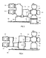
- two switch disconnector and earthing switch compartments incorporated in two busbars are coupled to two inputs on a vertical side of a coupling element (Cy).
- An output of the coupling element (Cy) is connected to an input of a horizontal upper face of the circuit breaker (Da).
- An output of the horizontal top of circuit breaker (Da), laterally disposed at the input of said circuit breaker is coupled to a bottom face of current transformer (Tc1) of vertical cylindrical shape and an output is coupled to an input of a lateral side of line disconnector (St3).
- Another side face of the line disconnector (St3) is connected to a fast-closing earthing switch (St4).
- An upper face of the line disconnector (St3) is connected to a voltage transformer (Tt).
- a lower face of the line disconnector (St3) is coupled to the cable connection compartment (Co) integrated in the lower part of a vertical column formed by the modules (Tt, St3, St4, Co) at the end of the bay.
- the circuit breaker (Da) is of cylindrical shape having a horizontal axis of revolution and its lower base (Ba) serves on the one hand as a base of transport placed on a base of a means of transport and on the other hand as a base for laying, fixing and maintaining the span on site.
- the breaker base (Ba) which mainly corresponds to the lowest part vertically of the span.
- connection compartment (Co) of cables (of dry or fluid type) integrated in the lower part of a vertical column formed by the modules (Tt, St3, St4, Co) at the end of the span can or must have a lower part adapted to be fixed to the ground preferably in an enclave dug under the surface of the ground to protect the connection said compartment (Co) with the ground (Ground). Therefore, it is necessary that the lower part of the connection compartment (Co) can optionally be removed during transport otherwise it presents a problem or a special arrangement of the lower transport base carrying the base (Ba).
- connection compartment (Co) with a height (C> 0) by providing for example that the compartment as the current transformer (Tc1) according to figure 1 having a coupling upstream of and with the vertical column formed by the modules (Tt, St3, St4, Co) at the end of the span provides for a vertical elongation (x) of its body so that said coupling is raised relative to a height (D) to guarantee no transport problem, said height (D) being the distance between the ground and said coupling without elongation (x).
- This type of elongation also has a disadvantage of raising the vertical column at the end of the span, and therefore require that the means of transport is larger volumetrically.
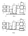
- the span is mainly the same as that of the figure 1 except that the cylindrical circuit-breaker (Da) has a vertical axis of revolution (instead of being horizontal as at the figure 1 ).
- the same problem due to a need for elongation (x) of the circuit breaker body (Da) is present for the lower part of the connection compartment is higher than the lower part of the circuit breaker (Da) and its base (Ba).
- connection compartment (Co) it is necessary to raise the lower part of the connection compartment (Co) by a height (C> 0) by providing for example that the circuit breaker compartment (Da) having a coupling via the current transformer (Tc1 ) with the vertical column formed by the modules (Tt, St3, St4, Co) at the output of the bay provides an elongation (x) so that said coupling is raised with respect to a height (D) to guarantee no transport problem , said height (D) being the distance between the ground and said coupling without elongation (x).
- figure 5 presents an alternative of elevation of the base (Ba) above the ground, but this solution remains heavier / massive to achieve and does not necessarily solve the problem of congestion during transport, even if the lower parts of the circuit breaker (Da ) and the connection compartment (Co) are quite close vertically (ideally for transport, the lower part of the connection compartment should be higher than the lower part of the circuit-breaker / base, but not too high for the span installation on the site).
- An object of the present invention is to provide a metal-enclosed electrical substation (GIS) arrangement comprising a horizontal span of several successively coupled compartments including a main compartment and a cable connection compartment integrated in the lower part of a vertical column. exit of span whose dimensioning or the need for elevation is minimized in order to facilitate the transport and installation on site of said post.
- GIS electrical substation
- the invention thus proposes a suitable arrangement of metal-clad substation according to claim 1.
- the arrangement according to the invention is flexibly adapted for a main compartment (Da) comprising at least one elongated circuit breaker and arranged either horizontally (see FIG. figures 2 and 3 ) vertically (see figure 6 ).
- Preferred modes of the arrangement according to the invention provide that at least the lower sub-compartment (Co2) is removable from the upper sub-compartment (Co1), so as to disassemble the lower sub-compartment (Co2) at least during transportation (see figure 2 ) and then easily fix it on site before placing the span on the ground and connect the two sub-compartments (see figure 3 or 6 ).
- a variant of the arrangement according to the invention provides that the lower sub-compartment (Co2) is movable relative to the upper sub-compartment (Co1), ideally by retraction, for example by sliding the sub-lower compartment (Co2) on or under the upper sub-compartment (Co1).
- the arrangement according to the invention provides that the lower sub-compartment (Co2) will comprise, on site, a base in the form of a ground support surface (Ground ) below ground level (that is, at least at an altitude equal to or less than the so-called ground level). Also, the arrangement according to the invention provides that the upper sub-compartment (Co1) will comprise a base in the form of a lower surface above ground level (i.e.
Landscapes
- Engineering & Computer Science (AREA)
- Power Engineering (AREA)
- Gas-Insulated Switchgears (AREA)
Abstract
La présente invention décrit un arrangement de poste électrique sous enveloppe métallique (GIS) comprenant : - une travée horizontale de plusieurs compartiments (St1, St2, Cy, Da, Tc1, Tc2, St3,...) successivement couplés dont un compartiment principal (Da, Tc1, Tc2) et un compartiment de connexion (Co) de câbles intégré en partie inférieure d'une colonne verticale (Tt, St3, Co) en sortie de travée; - le compartiment principal (Da) est disposé sur une base inférieure (Ba), ladite base formant un pied de la travée sur une surface horizontale au sol (Sol) . L'arrangement selon l'invention se caractérise en ce que le compartiment de connexion (Co) est subdivisé verticalement en au moins deux sous-compartiments supérieur et inférieur (Col, Co2), de façon à modifier sa hauteur.The present invention describes a metal-enclosed electrical station (GIS) arrangement comprising: - A horizontal span of several compartments (St1, St2, Cy, Da, Tc1, Tc2, St3, ...) successively coupled including a main compartment (Da, Tc1, Tc2) and a connection compartment (Co) of integrated cables in the lower part of a vertical column (Tt, St3, Co) at the end of the span; - The main compartment (Da) is disposed on a lower base (Ba), said base forming a foot of the span on a horizontal surface on the ground (Ground). The arrangement according to the invention is characterized in that the connection compartment (Co) is subdivided vertically into at least two upper and lower subcompartments (Col, Co2), so as to change its height.
Description
La présente invention concerne un arrangement de poste électrique sous enveloppe électrique selon le préambule de la revendication 1.The present invention relates to an arrangement of electrical substation under electric envelope according to the preamble of claim 1.
Un poste électrique sous enveloppe métallique (ou Gas-Insulated Switchgear en anglais, communément désigné par la terminologie GIS) comporte une enveloppe métallique, mise à la terre, contenant un gaz d'isolation tel que l'hexafluorure de soufre. Cette enveloppe métallique sous forme de travée, généralement subdivisée en plusieurs compartiments séparés par des cloisons isolantes, renferme des appareils de connexion, tels que des sectionneurs et sectionneurs de terre, des disjoncteurs, ou encore d'autres équipements électriques tels que des transformateurs de courant et de tension. Les disjoncteurs permettent de connecter des jeux de barres avec des lignes ou des câbles d'alimentation électrique et assurent l'interruption de courant électrique au moyen d'ampoules de coupure électrique. Les parties actives des appareils de connexion et des autres équipements électriques, qui sont soumises à la tension, sont isolées de l'enveloppe métallique mise à la terre par le gaz d'isolation et maintenues par les cloisons isolantes. Les appareils peuvent être par conception monophasés, avec une enveloppe par phase, ou bien par conception triphasés, avec une enveloppe commune pour les trois phases.A metal-enclosed electrical substation (or Gas-Insulated Switchgear, commonly referred to as GIS terminology) has a metal shell, grounded, containing an insulating gas such as sulfur hexafluoride. This metal envelope in the form of a span, generally divided into several compartments separated by insulating partitions, encloses connection devices, such as disconnectors and earthing switches, circuit breakers, or other electrical equipment such as current transformers. and tension. Circuit breakers are used to connect busbars with power lines or cables and provide power interruption by means of power cut-off bulbs. The live parts of the connection apparatus and other electrical equipment, which are subject to voltage, are isolated from the metal casing grounded by the insulating gas and held by the insulating partitions. The devices can be single-phase design, with one envelope per phase, or three-phase design, with a common envelope for the three phases.
Afin d'illustrer clairement l'état de la technique lié à l'invention, un exemple non limitatif de travée sous enveloppe métallique est présenté selon les
- une travée horizontale de plusieurs compartiments (st1, St2, Cy, Da, Tc1, Tc2, St3, ...) successivement couplés dont un compartiment principal (Da, Tc1, Tc2) et un compartiment de connexion (Co) de câbles intégré en partie inférieure d'une colonne verticale (Tt, St3, Co) en sortie de travée;
- le compartiment principal (Da) est disposé sur une base inférieure (Ba), ladite base formant un pied de la travée sur une surface horizontale au sol (Sol).
- a horizontal span of several compartments (st1, St2, Cy, Da, Tc1, Tc2, St3, ...) successively coupled, including a main compartment (Da, Tc1, Tc2) and a connection compartment (Co) integrated cables in lower part of a vertical column (Tt, St3, Co) at the end of the span;
- the main compartment (Da) is disposed on a lower base (Ba), said base forming a foot of the span on a horizontal surface on the ground (Ground).
Dans l'ensemble des figures de la présente de demande de brevet, les divers compartiments mentionnés ci-dessus à titre d'exemple de travée sont abrégés/référenciés selon la liste suivante présentant leur fonction technique :
- St1, St2 = Sectionneurs d'aiguillage et sectionneurs de terre incorporés dans deux jeux de barres (haut St1 et bas St2)
- Cy = Elément de couplage
- Da = Disjoncteur
- Tc1, Tc2 = Transformateurs de courant
- St3 sectionneur de ligne
- Tt = transformateur de tension
- St4 = Sectionneur de terre à pouvoir de fermeture à manoeuvre rapide
- Co = Boitier de connexion de câbles entre la travée et une conduite au sol.
- St1, St2 = Switch disconnectors and earth disconnectors incorporated in two busbars (top St1 and bottom St2)
- Cy = Coupling element
- Da = Breaker
- Tc1, Tc2 = Current transformers
- St3 line disconnector
- Tt = voltage transformer
- St4 = Quick Disconnect Closing Disconnector
- Co = Cable connection box between span and ground pipe.
- une travée horizontale de plusieurs compartiments (St1, St2, Cy, Da, Tc1, ...) successivement couplés dont un compartiment principal (Da, Tc1) et un compartiment de connexion (Co) de câbles intégré en partie inférieure d'une colonne verticale (Tt, St3, St4, Co) en sortie de travée;
- le compartiment principal (Da) est disposé sur une base inférieure (Ba), ladite base formant un pied de la travée sur une surface horizontale au sol (Sol) .
- a horizontal span of several compartments (St1, St2, Cy, Da, Tc1, ...) successively coupled, including a main compartment (Da, Tc1) and a cable connection compartment (Co) integrated in the lower part of a column vertical (Tt, St3, St4, Co) at the end of the span;
- the main compartment (Da) is disposed on a lower base (Ba), said base forming a foot of the span on a horizontal surface on the ground (Ground).
Plus précisément, deux compartiments de sectionneurs d'aiguillage et sectionneurs de terre incorporés dans deux jeux de barres (sectionneur haut St1, et sectionneur bas St2) sont couplés à deux entrées sur une face verticale d'un élément de couplage (Cy). Une sortie de l'élément de couplage (Cy) est reliée à une entrée d'une face supérieure horizontale de disjoncteur (Da). Une sortie de la face supérieure horizontale de disjoncteur (Da), latéralement disposée à l'entrée du dit disjoncteur est couplée à une entrée de face inférieure de transformateur de courant (Tc1) de forme cylindrique verticale et dont une sortie est couplée à une entrée d'une face latérale de sectionneur de ligne (St3). Une autre face latérale du sectionneur de ligne (St3) est reliée à un sectionneur de terre (St4) à pouvoir de fermeture à manoeuvre rapide. Une face supérieure du sectionneur de ligne (St3) est reliée à un transformateur de tension (Tt). Enfin, une face inférieure du sectionneur de ligne (St3) est couplée au compartiment de connexion (Co) de câbles intégré en partie inférieure d'une colonne verticale formés par les modules (Tt, St3, St4, Co) en sortie de travée.Specifically, two switch disconnector and earthing switch compartments incorporated in two busbars (high disconnector St1, and low disconnector St2) are coupled to two inputs on a vertical side of a coupling element (Cy). An output of the coupling element (Cy) is connected to an input of a horizontal upper face of the circuit breaker (Da). An output of the horizontal top of circuit breaker (Da), laterally disposed at the input of said circuit breaker is coupled to a bottom face of current transformer (Tc1) of vertical cylindrical shape and an output is coupled to an input of a lateral side of line disconnector (St3). Another side face of the line disconnector (St3) is connected to a fast-closing earthing switch (St4). An upper face of the line disconnector (St3) is connected to a voltage transformer (Tt). Finally, a lower face of the line disconnector (St3) is coupled to the cable connection compartment (Co) integrated in the lower part of a vertical column formed by the modules (Tt, St3, St4, Co) at the end of the bay.
Généralement, tous les compartiments décrits ci-dessus sont assemblés, remplis de gaz, puis testés en usine, avant d'être transportés sous forme de bloc assemblé de travée sur un site présentant une surface de réception au sol (Sol) apte à supporter une base (Ba) de pose et maintien de face inférieure (= face de dessous selon direction verticale) du compartiment de disjoncteur (Da).Generally, all compartments described above are assembled, filled with gas, then tested at the factory, before being transported as an assembled block of span on a site having a receiving surface on the ground (Ground) able to support a base (Ba) for installation and maintenance of the lower face (= bottom face in vertical direction) of the circuit-breaker compartment (Da).
En
En
Analoguement à la solution d'élongation (x) du corps de disjoncteur (Da) selon
Un but de la présente invention est de proposer un arrangement de poste électrique sous enveloppe métallique (GIS) comprenant une travée horizontale de plusieurs compartiments successivement couplés dont un compartiment principal et un compartiment de connexion de câbles intégré en partie inférieure d'une colonne verticale en sortie de travée dont le dimensionnement ou la nécessité de surélévation est minimisé afin de pouvoir faciliter le transport et l'installation sur site dudit poste.An object of the present invention is to provide a metal-enclosed electrical substation (GIS) arrangement comprising a horizontal span of several successively coupled compartments including a main compartment and a cable connection compartment integrated in the lower part of a vertical column. exit of span whose dimensioning or the need for elevation is minimized in order to facilitate the transport and installation on site of said post.
L'invention propose ainsi un arrangement adapté de poste électrique sous enveloppe métallique selon la revendication 1.The invention thus proposes a suitable arrangement of metal-clad substation according to claim 1.
A partir d'un arrangement de poste électrique sous enveloppe métallique (GIS) comprenant :
- une travée horizontale de plusieurs compartiments successivement couplés dont un compartiment principal et un compartiment de connexion de câbles intégré en partie inférieure d'une colonne verticale en sortie de travée;
- le compartiment principal est disposé sur une base inférieure (Ba), ladite base formant un pied de la travée sur une surface horizontale au sol (Sol) ;
- a horizontal span of several successively coupled compartments including a main compartment and a cable connection compartment integrated in the lower part of a vertical column at the end of the bay;
- the main compartment is disposed on a lower base (Ba), said base forming a foot of the span on a horizontal surface on the ground (Ground);
Un ensemble de sous-revendications présente également des avantages de l'invention et sont plus amplement décrits au travers des exemples de réalisation fournis à l'aide de fiures décrites :
- Figure 2 :
- schéma d'un arrangement selon l'invention en configuration de transport sur la base de l'exemple fourni en
figure 1 , - Figure 3 :
- schéma d'un arrangement selon l'invention en configuration d'installation sur site sur la base de l'exemple fourni en
figure 1 , - Figure 6 :
- schéma d'un arrangement selon l'invention en configuration d'installation sur site sur la base de l'exemple fourni aux
figures 4 et5 .
- Figure 2:
- scheme of an arrangement according to the invention in transport configuration on the basis of the example provided in
figure 1 , - Figure 3:
- schematic of an arrangement according to the invention in an on-site installation configuration on the basis of the example provided in
figure 1 , - Figure 6:
- scheme of an arrangement according to the invention in an on-site installation configuration on the basis of the example provided to the
figures 4 and5 .
Toutes les
- une travée horizontale de plusieurs compartiments (St1, St2, Cy, Da, Tc1 ou Tc2, St3, St4, Tt, Co1, Co2) successivement couplés dont un compartiment principal (Da, Tc1 ou Tc2) et un compartiment de connexion (Co = Co1, Co2) de câbles intégré en partie inférieure d'une colonne verticale (Tt, St3, St4, Co=CO1 ; Co2) en sortie de travée;
- le compartiment principal (Da) est disposé sur une base inférieure (Ba), ladite base formant un pied de la travée sur une surface horizontale au sol (Sol) ;
- a horizontal span of several compartments (St1, St2, Cy, Da, Tc1 or Tc2, St3, St4, Tt, Co1, Co2) successively coupled, including a main compartment (Da, Tc1 or Tc2) and a connection compartment (Co = Co1, Co2) of cables integrated in the lower part of a vertical column (Tt, St3, St4, Co = CO1, Co2) at the end of the span;
- the main compartment (Da) is disposed on a lower base (Ba), said base forming a foot of the span on a horizontal surface on the ground (Ground);
Cette modification de hauteur permet de diminuer la hauteur de la colonne verticale en sortie de travée, en ce que :
- une hauteur de partie basse du sous-compartiment de connexion supérieur (Co1) est avantageusement plus élevée (verticalement, C>0) que celle de la base du disjoncteur (Da) ou sa base (Ba), permettant par rétractation ou retrait du sous-compartiment inférieur (Co2) une surélévation de partie basse de la colonne verticale de sortie de travée nécessaire lors du transport du poste.
- la partie basse de sous-compartiment de connexion inférieur (Co2) est avantageusement plus basse (verticalement, C<0) que celle de la base du disjoncteur (Da) ou sa base (Ba) lorsque les deux sous-compartiments inférieurs et supérieurs sont physiquement déployés ou couplés l'un sur l'autre lors de l'installation sur site.
- a lower part height of the upper connection sub-compartment (Co1) is advantageously higher (vertically, C> 0) than that of the base of the circuit breaker (Da) or its base (Ba), allowing by retraction or withdrawal of the sub lower compartment (Co2) an elevation of the lower part of the vertical column of exit of span necessary during the transport of the station.
- lower part of lower connection sub-compartment (Co2) is advantageously lower (vertically, C <0) than that of the base of the circuit breaker (Da) or its base (Ba) when the two sub-upper and lower compartments are physically deployed or coupled one on the other when installing on site.
Il n'y a donc plus besoin de prévoir d'élongation de disjoncteur, de compartiment de couplage ou tout autre compartiment de type GIS (sous gaz), puisque seuls les sous-compartiments de câbles (hors gaz) jouent le rôle de rallonges ou de raccourcisseurs de la colonne verticale en sortie de travée. Ceci présente donc certes un double avantage lors du transport et sur site, mais aussi d'éviter une élongation/surélévation de modules de type GIS (impliquant une hausse de volume/masse/coûts) .There is no longer any need to provide circuit breaker elongation, coupling compartment or any other GIS type compartment (under gas), since only the sub-compartments of cables (excluding gases) act as extensions or shortening of the vertical column at the end of the span. This therefore presents a double advantage during transport and on site, but also to avoid an elongation / elevation of GIS type modules (involving an increase in volume / mass / costs).
L'arrangement selon l'invention est flexiblement adapté pour un compartiment principal (Da) comprenant au moins un disjoncteur de forme allongée et disposé soit horizontalement (voir
Des modes préférentiels de l'arrangement selon l'invention prévoient qu'au moins le sous-compartiment inférieur (Co2) est amovible du sous-compartiment supérieur (Co1), de façon à démonter le sous-compartiment inférieur (Co2) au moins durant le transport (voir
Une variante de l'arrangement selon l'invention prévoit que le sous-compartiment inférieur (Co2) est mobile par rapport au sous-compartiment supérieur (Co1), idéalement par rétractage, par exemple par coulisse du sous-compartiment inférieur (Co2) sur ou sous le sous-compartiment supérieur (Co1).A variant of the arrangement according to the invention provides that the lower sub-compartment (Co2) is movable relative to the upper sub-compartment (Co1), ideally by retraction, for example by sliding the sub-lower compartment (Co2) on or under the upper sub-compartment (Co1).
Principalement et dès sa conception pour faciliter transport et installation de poste, l'arrangement selon l'invention prévoit que le sous-compartiment inférieur (Co2) comprendra, sur site, une base sous forme d'une surface d'appui au sol (Sol) située en dessous du niveau du sol (c'est-à-dire au moins à une altitude égale ou inférieure au dit sol). Egalement, l'arrangement selon l'invention prévoit que le sous-compartiment supérieur (Co1) comprendra une base sous forme d'une surface inférieure située au-dessus du niveau du sol (c'est-à-dire au moins à une altitude plus élevée que le sol (Sol) ou la base (Ba) de disjoncteur), de sorte que, pour sur site, l'installation du dit poste soit garantie par une mise à même altitude et une solidarisation mécanique de la surface inférieure du sous-compartiment supérieur (Co1) avec la surface supérieure du sous-compartiment inférieur (Co2).Mainly and from its conception to facilitate transport and installation of post, the arrangement according to the invention provides that the lower sub-compartment (Co2) will comprise, on site, a base in the form of a ground support surface (Ground ) below ground level (that is, at least at an altitude equal to or less than the so-called ground level). Also, the arrangement according to the invention provides that the upper sub-compartment (Co1) will comprise a base in the form of a lower surface above ground level (i.e. at least at an altitude higher than the ground (ground) or the base (ba) of circuit breaker), so that for on site, the installation of said station is guaranteed by placing at the same altitude and a mechanical fastening of the lower surface of the sub upper compartment (Co1) with the upper surface of the lower sub-compartment (Co2).
Claims (6)
le compartiment de connexion (Co) est subdivisé verticalement en au moins deux sous-compartiments supérieur et inférieur (Col, Co2), de façon à modifier sa hauteur.
the connection compartment (Co) is subdivided vertically into at least two upper and lower subcompartments (Col, Co2) so as to change its height.
Priority Applications (2)
| Application Number | Priority Date | Filing Date | Title |
|---|---|---|---|
| EP13290159.6A EP2824780A1 (en) | 2013-07-11 | 2013-07-11 | Arrangement of a gas-insulated substation |
| PCT/EP2014/061989 WO2015003865A1 (en) | 2013-07-11 | 2014-06-10 | Substation arrangement in an electrical envelope |
Applications Claiming Priority (1)
| Application Number | Priority Date | Filing Date | Title |
|---|---|---|---|
| EP13290159.6A EP2824780A1 (en) | 2013-07-11 | 2013-07-11 | Arrangement of a gas-insulated substation |
Publications (1)
| Publication Number | Publication Date |
|---|---|
| EP2824780A1 true EP2824780A1 (en) | 2015-01-14 |
Family
ID=48900911
Family Applications (1)
| Application Number | Title | Priority Date | Filing Date |
|---|---|---|---|
| EP13290159.6A Withdrawn EP2824780A1 (en) | 2013-07-11 | 2013-07-11 | Arrangement of a gas-insulated substation |
Country Status (2)
| Country | Link |
|---|---|
| EP (1) | EP2824780A1 (en) |
| WO (1) | WO2015003865A1 (en) |
Citations (2)
| Publication number | Priority date | Publication date | Assignee | Title |
|---|---|---|---|---|
| US4837662A (en) * | 1986-10-07 | 1989-06-06 | Mitsubishi Denki Kabushiki Kaisha | Gas insulated switchgear |
| EP2031718A1 (en) * | 2006-06-19 | 2009-03-04 | Mitsubishi Electric Corporation | Gas insulated power apparatus |
-
2013
- 2013-07-11 EP EP13290159.6A patent/EP2824780A1/en not_active Withdrawn
-
2014
- 2014-06-10 WO PCT/EP2014/061989 patent/WO2015003865A1/en active Application Filing
Patent Citations (2)
| Publication number | Priority date | Publication date | Assignee | Title |
|---|---|---|---|---|
| US4837662A (en) * | 1986-10-07 | 1989-06-06 | Mitsubishi Denki Kabushiki Kaisha | Gas insulated switchgear |
| EP2031718A1 (en) * | 2006-06-19 | 2009-03-04 | Mitsubishi Electric Corporation | Gas insulated power apparatus |
Also Published As
| Publication number | Publication date |
|---|---|
| WO2015003865A1 (en) | 2015-01-15 |
Similar Documents
| Publication | Publication Date | Title |
|---|---|---|
| FR2459565A1 (en) | Medium voltage metal encased gas filled switchgear - has circuit breaker sharing casing with disconnector and bus=bar system | |
| EP1329008B2 (en) | High voltage hybrid station with opposite busbars and shielded cutoff and switching modules | |
| EP2824780A1 (en) | Arrangement of a gas-insulated substation | |
| CA2351120A1 (en) | Hybrid high voltage station with metal-clad bus bars and air insulated back-up line | |
| FR2555830A1 (en) | Shielded substation with pressurised-gas insulation | |
| EP2192663B1 (en) | High voltage metal enclosed electrical switchgear | |
| EP3001521A1 (en) | Medium-voltage electrical switchgear with metering of the current | |
| FR2532791A1 (en) | HIGH VOLTAGE DISTRIBUTION CELL FOR TRANSFORMATION STATION | |
| FR2782418A1 (en) | Transformer substation, comprises a compact layout to reduce footprint of substation enclosure | |
| CA1127285A (en) | Very high voltage electric station | |
| FR2708392A1 (en) | Medium-voltage cell in a metal casing with auto-isolating circuit breaker | |
| WO2005078882A1 (en) | Transformer station with a retention tank | |
| EP1030334A1 (en) | Medium voltage load break switch module and corresponding power station | |
| WO2016012444A1 (en) | Clip for connecting a low-current device to a gas insulated substation allowing said device to be disconnected for an operational test phase of the substation | |
| CA1177915A (en) | Current transformer | |
| WO2014128251A1 (en) | Method of extracting a jacket of a gas insulated substation (gis) under a metal casing | |
| EP0002398A1 (en) | Improvements in current distribution cells | |
| FR2914509A1 (en) | ARCHITECTURE OF AN ENERGY EXHAUST STATION OF AN ELECTRIC POWER GENERATION PLANT | |
| EP0348312B2 (en) | Shielded station for a high voltage network | |
| FR2559533A1 (en) | Electrical transformer station made of precast concrete. | |
| FR2629283A1 (en) | Bay of a high-voltage shielded substation | |
| FR2735914A1 (en) | Medium tension gas-insulated electricity distribution installation | |
| CH380799A (en) | High voltage electrical distribution installation | |
| FR2921524A1 (en) | Average/high voltage electrical energy distribution panel, has envelope extended above bar assembly and designed such that bars remain confined in dry portion of cavity, where cavity is sealingly closed towards top and opened towards bottom | |
| CA1118825A (en) | Insulating barrier between the two compartments of a high voltage circuit-breaker cell |
Legal Events
| Date | Code | Title | Description |
|---|---|---|---|
| 17P | Request for examination filed |
Effective date: 20130711 |
|
| AK | Designated contracting states |
Kind code of ref document: A1 Designated state(s): AL AT BE BG CH CY CZ DE DK EE ES FI FR GB GR HR HU IE IS IT LI LT LU LV MC MK MT NL NO PL PT RO RS SE SI SK SM TR |
|
| AX | Request for extension of the european patent |
Extension state: BA ME |
|
| PUAI | Public reference made under article 153(3) epc to a published international application that has entered the european phase |
Free format text: ORIGINAL CODE: 0009012 |
|
| STAA | Information on the status of an ep patent application or granted ep patent |
Free format text: STATUS: THE APPLICATION IS DEEMED TO BE WITHDRAWN |
|
| 18D | Application deemed to be withdrawn |
Effective date: 20150715 |