EP2824687A1 - Electro-magnetic contactor - Google Patents
Electro-magnetic contactor Download PDFInfo
- Publication number
- EP2824687A1 EP2824687A1 EP14174691.7A EP14174691A EP2824687A1 EP 2824687 A1 EP2824687 A1 EP 2824687A1 EP 14174691 A EP14174691 A EP 14174691A EP 2824687 A1 EP2824687 A1 EP 2824687A1
- Authority
- EP
- European Patent Office
- Prior art keywords
- fixed
- contact
- fixed contact
- electromagnetic contactor
- bobbin
- Prior art date
- Legal status (The legal status is an assumption and is not a legal conclusion. Google has not performed a legal analysis and makes no representation as to the accuracy of the status listed.)
- Withdrawn
Links
- 238000005192 partition Methods 0.000 claims description 6
- 239000000126 substance Substances 0.000 description 14
- 238000000034 method Methods 0.000 description 7
- 230000000694 effects Effects 0.000 description 5
- 238000011109 contamination Methods 0.000 description 4
- 238000004519 manufacturing process Methods 0.000 description 4
- 239000000428 dust Substances 0.000 description 3
- 230000004308 accommodation Effects 0.000 description 2
- 238000012986 modification Methods 0.000 description 2
- 230000004048 modification Effects 0.000 description 2
- 230000002159 abnormal effect Effects 0.000 description 1
- 230000008033 biological extinction Effects 0.000 description 1
- 230000015572 biosynthetic process Effects 0.000 description 1
- 238000007599 discharging Methods 0.000 description 1
- 238000004049 embossing Methods 0.000 description 1
- 238000005516 engineering process Methods 0.000 description 1
- 238000000926 separation method Methods 0.000 description 1
Images




Classifications
-
- H—ELECTRICITY
- H01—ELECTRIC ELEMENTS
- H01H—ELECTRIC SWITCHES; RELAYS; SELECTORS; EMERGENCY PROTECTIVE DEVICES
- H01H1/00—Contacts
- H01H1/64—Protective enclosures, baffle plates, or screens for contacts
-
- H—ELECTRICITY
- H01—ELECTRIC ELEMENTS
- H01H—ELECTRIC SWITCHES; RELAYS; SELECTORS; EMERGENCY PROTECTIVE DEVICES
- H01H50/00—Details of electromagnetic relays
- H01H50/02—Bases; Casings; Covers
- H01H50/023—Details concerning sealing, e.g. sealing casing with resin
-
- H—ELECTRICITY
- H01—ELECTRIC ELEMENTS
- H01H—ELECTRIC SWITCHES; RELAYS; SELECTORS; EMERGENCY PROTECTIVE DEVICES
- H01H1/00—Contacts
- H01H1/06—Contacts characterised by the shape or structure of the contact-making surface, e.g. grooved
-
- H—ELECTRICITY
- H01—ELECTRIC ELEMENTS
- H01H—ELECTRIC SWITCHES; RELAYS; SELECTORS; EMERGENCY PROTECTIVE DEVICES
- H01H50/00—Details of electromagnetic relays
- H01H50/16—Magnetic circuit arrangements
- H01H50/18—Movable parts of magnetic circuits, e.g. armature
- H01H50/30—Mechanical arrangements for preventing or damping vibration or shock, e.g. by balancing of armature
- H01H50/305—Mechanical arrangements for preventing or damping vibration or shock, e.g. by balancing of armature damping vibration due to functional movement of armature
-
- H—ELECTRICITY
- H01—ELECTRIC ELEMENTS
- H01H—ELECTRIC SWITCHES; RELAYS; SELECTORS; EMERGENCY PROTECTIVE DEVICES
- H01H50/00—Details of electromagnetic relays
- H01H50/54—Contact arrangements
- H01H50/546—Contact arrangements for contactors having bridging contacts
Definitions
- the present invention relates to an electromagnetic contactor, and more particularly, an electromagnetic contactor provided with a fixed contact formed with a protection base stably fixed to prevent the inflow of foreign substances and reduce vibration, thereby reducing the contamination of a fixed contact point as well as reducing a conduction failure rate.
- electromagnetic contactor is a type of electrical circuit switching device for transferring a mechanical drive and current signal using the principle of an electromagnet, and provided in various industrial facilities, machines, vehicles, and the like.
- FIG. 1 is an internal perspective view illustrating an electromagnetic contactor according to the related art
- FIG. 2 is a partial cross-sectional view illustrating an electromagnetic contactor according to the related art
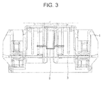
- FIG. 3 is a front view illustrating a fixed contact of the electromagnetic contactor according to the related art.
- the external appearance of an electromagnetic contactor is formed by an upper and a lower frame 1, 2, and a plurality of fixed contact 3 connected to the power input side or load side terminal of an electrical circuit, respectively, are provided at the upper frame 1.
- a bobbin coil 4 generating a magnetic force according to the application of power is provided at a lower portion of an internal space formed between the upper and the lower frame 1, 2, and a fixed core 5 magnetized according to the magnetic force generation of the bobbin coil 4 is provided at a lower portion of the bobbin coil 4, and a movable core 6 performing an up-and-down movement according to the magnetic force generation and extinction is provided at an upper portion of the fixed core 5.
- a return spring 7 providing a restoring force to the movable core 6 is provided between the bobbin coil 4 and the movable core 6.
- a cross bar 8 performing an up-and-down movement along with the movable core 6 is provided at an upper portion of the movable core 6, and a movable contact 9 electrically connected or short-circuited to the each fixed contact 3 is provided at the cross bar 8.
- the fixed core 5 provided at a lower portion thereof is magnetized as energizing the bobbin coil 4.
- the movable core 6 provided over an upper portion of the fixed core 5 moves downward to the fixed core 5 due to an attractive force by the magnetic force of the magnetized fixed core 5, and the cross bar 8 coupled to the movable core 6 moves downward at the same time.
- the movable contact 9 coupled to the cross bar 8 is connected to the fixed contact 3 fixed and provided at the upper frame 1.
- a contact mounting structure in an electromagnetic contactor has been disclosed in Korean Patent Registration No. 10-0518256 .
- an orientation between a movable contact 60 and a fixed contact 80 is disposed perpendicular to an orientation between a movable contact 16 and a fixed contact 15, thereby preventing a contact failure phenomenon and an abnormal noise phenomenon due to dust generation.
- the present invention is contrived to solve the foregoing problems, and an aspect of the present invention is to provide an electromagnetic contactor provided with a fixed contact formed with a protection base stably fixed to prevent the inflow of foreign substances and reduce vibration, thereby reducing the contamination of a fixed contact point as well as reducing a conduction failure rate.
- An electromagnetic contactor may include a lower frame; a fixed core provided to be inserted into the lower frame; a bobbin provided at an upper portion of the fixed core; a coil coupled to the bobbin; a movable core provided at an upper portion of the bobbin; a cross bar coupled to an upper portion of the movable core; a movable contact coupled to the cross bar to move in an upward and downward direction; an upper frame configured to cover the lower frame; and a fixed contact fixed to part of the upper frame, wherein a protection base is formed to be protruded from an intermediate portion of the fixed contact.
- the transverse cross-sectional area of the protection base may be formed in a circular shape.
- the diameter of the protection base may be formed to be less than the width of the fixed contact.
- the protection base may be brought into contact with an inner partition wall of the upper frame.
- a protection base may be formed at a fixed contact, thereby having an effect of reducing the contamination phenomenon of the fixed contact point.
- a protection base at a higher position than that of the fixed contact point may be first brought into contact with the bottom, thereby preventing foreign substances from being adhered to the fixed contact.
- the inflow of foreign substances may be suppressed while being used, thereby having an effect of reducing the amount of external foreign substances from flowing therein.
- the vibration of the fixed contact may be reduced due to the protection base being brought into contact with an inner partition wall, thereby having an effect of stably fixing the fixed contact.
- FIG. 4 is an internal perspective view illustrating an electromagnetic contactor according to the present disclosure
- FIG. 5 is a perspective view illustrating a fixed contact of the electromagnetic contactor according to the present disclosure
- FIG. 6a and 6b are a plan view and a front view of FIG. 5
- FIG. 7 is a partial perspective view illustrating an electromagnetic contactor according to the present disclosure.
- An electromagnetic contactor may include a lower frame 10; a fixed core 20 provided to be inserted into the lower frame 10; a bobbin 30 provided at an upper portion of the fixed core 20; a coil 35 coupled to the bobbin 30; a movable core 40 provided at an upper portion of the bobbin 30; a cross bar 50 coupled to an upper portion of the movable core 40; a movable contact 60 coupled to the cross bar 50 to move in an upward and downward direction; an upper frame 70 configured to cover the lower frame 10; and a fixed contact 80 fixed to part of the upper frame 10.
- a protection base 85 is formed at an intermediate portion of the fixed contact 80.
- the lower frame 10 is formed in a rectangular shape as a whole, and an upper surface thereof is open to form an accommodation space therein.
- the bobbin 30 and coil 35 are provided at a central portion of the lower frame 10.
- the fixed core 20 is coupled to an inner bottom of the lower frame 10.
- the fixed core 20 is magnetized according to the flow of current to have a magnetic force.
- the coil 35 is wound around the bobbin 30, and the bobbin 30 is fixed and coupled to one side of the lower frame 10.
- a current flows through the coil 35 coupled to the bobbin 30, a magnetic force is formed at the fixed core 20.
- the bobbin 30 may include an upper plate, a lower plate and a coil accommodation portion, and a return spring 39 is provided on the upper plate of the bobbin 30.
- the movable core 40 is provided at an upper portion of the bobbin 30, and moves downward by the magnetic force of the fixed core 20.
- an elastic force is stored in the return spring 39, and the stored elastic force is released as a restoring force to move the movable core 40 in an upward direction to an original location when the magnetic force of the fixed core 20 becomes extinct.
- the cross bar 50 is coupled to an upper portion of the movable core 40 to move upward along with the movable core 40.
- the cross bar 50 is coupled to the movable contact 60 and connected to the fixed contact 80 according to the downward movement of the movable core 40.
- the fixed contact 80 is provided to be brought into contact with or separated from the movable contact 60 at a portion adjacent to the movable contact 60 on both sides of the upper frame 70.
- a fixed contact point 81 is formed at one side upper portion of the fixed contact 80, and a screw hole 82 is formed at the other side thereof.
- the fixed contact point 81 may be formed with a plurality of embossings along the length direction to facilitate the fixed contact point 81 to be separated from the movable contact point 61.
- the protection base 85 is formed to be protruded from an intermediate portion of the fixed contact 80 to prevent foreign substances from flowing in from the outside.
- the transverse cross-sectional area of the protection base 85 may be formed in a circular shape to minimize foreign substances from being brought into contact therewith.
- the protection base 85 is stably formed in a truncated conical shape.
- the protection base 85 Due to the formation of the protection base 85, foreign substances cannot easily flow therein from the outside through an opening portion 76 of the grid 75 of the upper frame 70. Furthermore, even when the fixed contact 80 is turned over during a component transport process or the like even in the fabrication process, the protection base 85 is brought into contact with the bottom but the fixed contact point 81 is not brought into contact with the bottom, thereby disallowing foreign substances to be adhered to the fixed contact point 81. The contamination of the fixed contact point 81 may be reduced to decrease the possibility of causing a conduction failure.
- an upper surface of the protection base 85 may be formed to be brought into contact with an inner partition wall 71 of the upper frame 70. Since the upper surface of the protection base 85 is brought into contact with the inner partition wall 71 of the upper frame 70, the vibration of the fixed contact 80 is restricted, thereby maintaining a state of being stably fixed and coupled to the upper frame 70 with no vibration. Accordingly, contact and separation between the fixed contact 80 and the movable contact 60 may be stably carried out, thereby stably operating the electromagnetic contactor.
- the fixed contact 80 and the movable contact 60 may be operated while being stably brought into contact with or separated from each other, thereby having an effect of reducing a conduction failure rate of the electromagnetic contactor.
- the diameter of the protection base 85 may be formed to be less than the width of the fixed contact 80. Accordingly, even when the protection base 85 is brought into contact with the inner partition wall 71 of the upper frame 70, a space is formed around the protection base 85, thereby forming a space capable of discharging an arc generated during the process of separating the fixed contact 80 from the movable contact 60.
Landscapes
- Physics & Mathematics (AREA)
- Electromagnetism (AREA)
- Switch Cases, Indication, And Locking (AREA)
Abstract
An electromagnetic contactor comprising a lower frame 10; a fixed core 20 provided to be inserted into the lower frame 10; a bobbin 30 provided at an upper portion of the fixed core 20; a coil 35 coupled to the bobbin 30; a movable core 40 provided at an upper portion of the bobbin 30; a cross bar 50 coupled to an upper portion of the movable core 40; a movable contact 60 coupled to the cross bar 50 to move in an upward and downward direction; an upper frame 70 configured to cover the lower frame 10; and a fixed contact 80 fixed to part of the upper frame 10, wherein a protection base 85 is formed to be protruded from an intermediate portion of the fixed contact 80.
Description
- The present invention relates to an electromagnetic contactor, and more particularly, an electromagnetic contactor provided with a fixed contact formed with a protection base stably fixed to prevent the inflow of foreign substances and reduce vibration, thereby reducing the contamination of a fixed contact point as well as reducing a conduction failure rate.
- In general, electromagnetic contactor is a type of electrical circuit switching device for transferring a mechanical drive and current signal using the principle of an electromagnet, and provided in various industrial facilities, machines, vehicles, and the like.
- First, the outline of the configuration and operation of an electromagnetic contactor according to the related art will be described.
FIG. 1 is an internal perspective view illustrating an electromagnetic contactor according to the related art, andFIG. 2 is a partial cross-sectional view illustrating an electromagnetic contactor according to the related art, andFIG. 3 is a front view illustrating a fixed contact of the electromagnetic contactor according to the related art. - According to an electromagnetic contactor in the related art, the external appearance of an electromagnetic contactor is formed by an upper and a
lower frame 1, 2, and a plurality offixed contact 3 connected to the power input side or load side terminal of an electrical circuit, respectively, are provided at the upper frame 1. - Furthermore, a
bobbin coil 4 generating a magnetic force according to the application of power is provided at a lower portion of an internal space formed between the upper and thelower frame 1, 2, and a fixedcore 5 magnetized according to the magnetic force generation of thebobbin coil 4 is provided at a lower portion of thebobbin coil 4, and amovable core 6 performing an up-and-down movement according to the magnetic force generation and extinction is provided at an upper portion of thefixed core 5. Areturn spring 7 providing a restoring force to themovable core 6 is provided between thebobbin coil 4 and themovable core 6. - In addition, a
cross bar 8 performing an up-and-down movement along with themovable core 6 is provided at an upper portion of themovable core 6, and amovable contact 9 electrically connected or short-circuited to the each fixedcontact 3 is provided at thecross bar 8. - In an electromagnetic contactor having the foregoing configuration, when a current is applied to the
bobbin coil 4, thefixed core 5 provided at a lower portion thereof is magnetized as energizing thebobbin coil 4. Themovable core 6 provided over an upper portion of the fixedcore 5 moves downward to thefixed core 5 due to an attractive force by the magnetic force of the magnetized fixedcore 5, and thecross bar 8 coupled to themovable core 6 moves downward at the same time. - Accordingly, the
movable contact 9 coupled to thecross bar 8 is connected to the fixedcontact 3 fixed and provided at the upper frame 1. - On the contrary, when the magnetic force of the
bobbin coil 4 becomes extinct, an attraction force for pulling themovable core 6 disappears, and themovable core 6 is separated from thefixed core 5 by a restoring force of thereturn spring 7 and moved upward to an original location. - However, according to such an electromagnetic contactor in the related art, foreign substances may adhere to a contact surface between the fixed
contact 3 and themovable contact 9 due to foreign substances such as dust or the like coming through theopening portion 10. When foreign substances adhere to a contact surface between the fixedcontact 3 and themovable contact 9, an electromagnetic force is weakened and it occurs a phenomenon in which the fixedcontact 3 and themovable contact 9 cannot be properly brought into contact with each other, thereby increasing a conduction failure rate due to this. Furthermore, the fixedcontact 3 may be turned over during a component transport process or the like even in the fabrication process, thereby causing foreign substances to be adhered to the contact surface. - As a technology proposed to solve the above-mentioned problems, a contact mounting structure in an electromagnetic contactor has been disclosed in Korean Patent Registration No.
10-0518256 movable contact 60 and a fixedcontact 80 is disposed perpendicular to an orientation between a movable contact 16 and a fixed contact 15, thereby preventing a contact failure phenomenon and an abnormal noise phenomenon due to dust generation. However, even in the above invention, it may be impossible to prevent dust from flowing in through the opening portion of a grid, and difficult to cope with the adhesion of foreign substances generated during the fabrication process or the like. - The present invention is contrived to solve the foregoing problems, and an aspect of the present invention is to provide an electromagnetic contactor provided with a fixed contact formed with a protection base stably fixed to prevent the inflow of foreign substances and reduce vibration, thereby reducing the contamination of a fixed contact point as well as reducing a conduction failure rate.
- An electromagnetic contactor according to an embodiment of the present disclosure may include a lower frame; a fixed core provided to be inserted into the lower frame; a bobbin provided at an upper portion of the fixed core; a coil coupled to the bobbin; a movable core provided at an upper portion of the bobbin; a cross bar coupled to an upper portion of the movable core; a movable contact coupled to the cross bar to move in an upward and downward direction; an upper frame configured to cover the lower frame; and a fixed contact fixed to part of the upper frame, wherein a protection base is formed to be protruded from an intermediate portion of the fixed contact.
- Here, the transverse cross-sectional area of the protection base may be formed in a circular shape.
- Furthermore, the diameter of the protection base may be formed to be less than the width of the fixed contact.
- Furthermore, the protection base may be brought into contact with an inner partition wall of the upper frame.
- According to an electromagnetic contactor in accordance with an embodiment of the present disclosure, a protection base may be formed at a fixed contact, thereby having an effect of reducing the contamination phenomenon of the fixed contact point. In other words, even when an operation is carried out while the fixed contact is turned over during the fabrication process, a protection base at a higher position than that of the fixed contact point may be first brought into contact with the bottom, thereby preventing foreign substances from being adhered to the fixed contact. Furthermore, the inflow of foreign substances may be suppressed while being used, thereby having an effect of reducing the amount of external foreign substances from flowing therein.
- Furthermore, the vibration of the fixed contact may be reduced due to the protection base being brought into contact with an inner partition wall, thereby having an effect of stably fixing the fixed contact.
- On the other hand, a conduction failure rate may be reduced due to the above-mentioned effects.
- The accompanying drawings, which are included to provide a further understanding of the invention and are incorporated in and constitute a part of this specification, illustrate embodiments of the invention and together with the description serve to explain the principles of the invention.
- In the drawings:
-
FIG. 1 is an internal perspective view illustrating an electromagnetic contactor in the related art; -
FIG. 2 is a partial perspective view illustrating an electromagnetic contactor according to the related art; -
FIG. 3 is a front view illustrating a fixed contact of the electromagnetic contactor according to the related art; -
FIG. 4 is an internal perspective view illustrating an electromagnetic contactor according to the present disclosure; -
FIG. 5 is a perspective view illustrating a fixed contact of the electromagnetic contactor; -
FIG. 6a and6b are a plan view and a front view illustrating a fixed contact of the electromagnetic contactor inFIG. 5 ; and -
FIG. 7 is a partial perspective view illustrating an electromagnetic contactor according to the present disclosure. - Hereinafter, a preferred embodiment of the present invention will be described in detail with reference to the accompanying drawings to such an extent that the present invention can be easily implemented by a person having ordinary skill in the art to which the present invention pertains, but it does not mean that the technical concept and scope of the present invention are limited due to this.
-
FIG. 4 is an internal perspective view illustrating an electromagnetic contactor according to the present disclosure, andFIG. 5 is a perspective view illustrating a fixed contact of the electromagnetic contactor according to the present disclosure, andFIG. 6a and6b are a plan view and a front view ofFIG. 5 , andFIG. 7 is a partial perspective view illustrating an electromagnetic contactor according to the present disclosure. An embodiment of the present disclosure will be described in detail with reference to the drawings. - An electromagnetic contactor according to an embodiment of the present disclosure may include a
lower frame 10; a fixedcore 20 provided to be inserted into thelower frame 10; abobbin 30 provided at an upper portion of the fixedcore 20; acoil 35 coupled to thebobbin 30; amovable core 40 provided at an upper portion of thebobbin 30; across bar 50 coupled to an upper portion of themovable core 40; amovable contact 60 coupled to thecross bar 50 to move in an upward and downward direction; anupper frame 70 configured to cover thelower frame 10; and a fixedcontact 80 fixed to part of theupper frame 10. Here, it is characterized in that aprotection base 85 is formed at an intermediate portion of the fixedcontact 80. - The
lower frame 10 is formed in a rectangular shape as a whole, and an upper surface thereof is open to form an accommodation space therein. Thebobbin 30 andcoil 35 are provided at a central portion of thelower frame 10. - The
fixed core 20 is coupled to an inner bottom of thelower frame 10. Thefixed core 20 is magnetized according to the flow of current to have a magnetic force. - The
coil 35 is wound around thebobbin 30, and thebobbin 30 is fixed and coupled to one side of thelower frame 10. When a current flows through thecoil 35 coupled to thebobbin 30, a magnetic force is formed at thefixed core 20. - The
bobbin 30 may include an upper plate, a lower plate and a coil accommodation portion, and areturn spring 39 is provided on the upper plate of thebobbin 30. - The
movable core 40 is provided at an upper portion of thebobbin 30, and moves downward by the magnetic force of the fixedcore 20. When themovable core 40 moves downward, an elastic force is stored in thereturn spring 39, and the stored elastic force is released as a restoring force to move themovable core 40 in an upward direction to an original location when the magnetic force of thefixed core 20 becomes extinct. - The
cross bar 50 is coupled to an upper portion of themovable core 40 to move upward along with themovable core 40. Thecross bar 50 is coupled to themovable contact 60 and connected to the fixedcontact 80 according to the downward movement of themovable core 40. - The fixed
contact 80 is provided to be brought into contact with or separated from themovable contact 60 at a portion adjacent to themovable contact 60 on both sides of theupper frame 70. Afixed contact point 81 is formed at one side upper portion of the fixedcontact 80, and ascrew hole 82 is formed at the other side thereof. Thefixed contact point 81 may be formed with a plurality of embossings along the length direction to facilitate thefixed contact point 81 to be separated from themovable contact point 61. Theprotection base 85 is formed to be protruded from an intermediate portion of the fixedcontact 80 to prevent foreign substances from flowing in from the outside. The transverse cross-sectional area of theprotection base 85 may be formed in a circular shape to minimize foreign substances from being brought into contact therewith. Preferably, theprotection base 85 is stably formed in a truncated conical shape. - Due to the formation of the
protection base 85, foreign substances cannot easily flow therein from the outside through an openingportion 76 of thegrid 75 of theupper frame 70. Furthermore, even when the fixedcontact 80 is turned over during a component transport process or the like even in the fabrication process, theprotection base 85 is brought into contact with the bottom but the fixedcontact point 81 is not brought into contact with the bottom, thereby disallowing foreign substances to be adhered to the fixedcontact point 81. The contamination of the fixedcontact point 81 may be reduced to decrease the possibility of causing a conduction failure. - Furthermore, an upper surface of the
protection base 85 may be formed to be brought into contact with aninner partition wall 71 of theupper frame 70. Since the upper surface of theprotection base 85 is brought into contact with theinner partition wall 71 of theupper frame 70, the vibration of the fixedcontact 80 is restricted, thereby maintaining a state of being stably fixed and coupled to theupper frame 70 with no vibration. Accordingly, contact and separation between the fixedcontact 80 and themovable contact 60 may be stably carried out, thereby stably operating the electromagnetic contactor. - The fixed
contact 80 and themovable contact 60 may be operated while being stably brought into contact with or separated from each other, thereby having an effect of reducing a conduction failure rate of the electromagnetic contactor. - On the other hand, furthermore, the diameter of the
protection base 85 may be formed to be less than the width of the fixedcontact 80. Accordingly, even when theprotection base 85 is brought into contact with theinner partition wall 71 of theupper frame 70, a space is formed around theprotection base 85, thereby forming a space capable of discharging an arc generated during the process of separating the fixedcontact 80 from themovable contact 60. - Although the present invention has been described with reference to the foregoing preferred embodiments, it will be easily recognized by those skilled in the art that various modifications and changes can be made without departing from the gist and scope of the invention, and it should be also clearly understood that all these modifications and changes fall in the appended claims.
Claims (4)
- An electromagnetic contactor, comprising:a lower frame 10;a fixed core 20 provided to be inserted into the lower frame 10;a bobbin 30 provided at an upper portion of the fixed core 20;a coil 35 coupled to the bobbin 30;a movable core 40 provided at an upper portion of the bobbin 30;a cross bar 50 coupled to an upper portion of the movable core 40;a movable contact 60 coupled to the cross bar 50 to move in an upward and downward direction;an upper frame 70 configured to cover the lower frame 10; anda fixed contact 80 fixed to part of the upper frame 10,wherein a protection base 85 is formed to be protruded from an intermediate portion of the fixed contact 80.
- The electromagnetic contactor of claim 1, wherein the transverse cross-sectional area of the protection base 85 is formed in a circular shape.
- The electromagnetic contactor of claim 2, wherein the diameter of the protection base 85 is formed to be less than the width of the fixed contact.
- The electromagnetic contactor of claim 1, wherein the protection base 85 is brought into contact with an inner partition wall 71 of the upper frame 70.
Applications Claiming Priority (1)
| Application Number | Priority Date | Filing Date | Title |
|---|---|---|---|
| KR20130076579 | 2013-07-01 |
Publications (1)
| Publication Number | Publication Date |
|---|---|
| EP2824687A1 true EP2824687A1 (en) | 2015-01-14 |
Family
ID=50982839
Family Applications (1)
| Application Number | Title | Priority Date | Filing Date |
|---|---|---|---|
| EP14174691.7A Withdrawn EP2824687A1 (en) | 2013-07-01 | 2014-06-27 | Electro-magnetic contactor |
Country Status (3)
| Country | Link |
|---|---|
| US (1) | US20150002247A1 (en) |
| EP (1) | EP2824687A1 (en) |
| CN (1) | CN104282495A (en) |
Families Citing this family (5)
| Publication number | Priority date | Publication date | Assignee | Title |
|---|---|---|---|---|
| KR101513207B1 (en) * | 2013-11-08 | 2015-04-17 | 엘에스산전 주식회사 | Magnetic contactor |
| KR101741586B1 (en) * | 2014-10-31 | 2017-05-30 | 엘에스산전 주식회사 | Crossbar Structure of Electro-magnetic Contactor |
| CN106558450A (en) * | 2015-09-30 | 2017-04-05 | 明光市和诚电气有限公司 | Relay |
| CN209045441U (en) * | 2018-09-27 | 2019-06-28 | 伊顿电气有限公司 | Contactor |
| CN119181622B (en) * | 2024-11-26 | 2025-08-26 | 德力西电气有限公司 | Auxiliary contact and electrical switch |
Citations (5)
| Publication number | Priority date | Publication date | Assignee | Title |
|---|---|---|---|---|
| US4525694A (en) * | 1983-09-23 | 1985-06-25 | Eaton Corporation | Electromagnetic contactor |
| JPS6096754U (en) * | 1983-12-08 | 1985-07-02 | 富士電機株式会社 | Magnetic contactor terminal barrier device |
| US5235304A (en) * | 1991-06-20 | 1993-08-10 | Fuji Electric Co., Ltd. | Dust preventing device for electromagnetic contactor |
| JPH11232981A (en) * | 1998-02-13 | 1999-08-27 | Mitsubishi Electric Corp | Switch |
| KR100518256B1 (en) | 2003-12-24 | 2005-10-04 | 엘에스산전 주식회사 | Structure for mounting contact terminal of magnetic contactor |
Family Cites Families (17)
| Publication number | Priority date | Publication date | Assignee | Title |
|---|---|---|---|---|
| US2433703A (en) * | 1943-02-03 | 1947-12-30 | Square D Co | Plunger electromagnet |
| US2399575A (en) * | 1943-05-06 | 1946-04-30 | Arrow Hart & Hegeman Electric | Electromagnetic switch |
| GB1053488A (en) * | 1963-12-26 | |||
| US3334319A (en) * | 1965-08-20 | 1967-08-01 | Ite Circuit Breaker Ltd | Electro-magnetic contactor |
| US3655934A (en) * | 1969-07-23 | 1972-04-11 | Square D Co | Movable contact structure for an electric switch |
| JPS581953Y2 (en) * | 1978-09-29 | 1983-01-13 | 株式会社デンソー | Plunger type electromagnetic relay |
| DE3211685C2 (en) * | 1982-03-30 | 1984-02-09 | Mannesmann AG, 4000 Düsseldorf | Contactors for controlling electric motors |
| FR2562321B1 (en) * | 1984-03-28 | 1986-08-01 | Telemecanique Electrique | ELECTRICAL SWITCHING APPARATUS COMPRISING A GAS-TIGHT CONTACTS PROTECTION COVER |
| EP0214652A3 (en) * | 1985-09-10 | 1988-04-06 | Omron Tateisi Electronics Co. | Electromagnetic relay |
| US4816794A (en) * | 1986-07-30 | 1989-03-28 | Omron Tateisi Electronics Co. | Electromagnetic relay |
| US4969844A (en) * | 1988-10-06 | 1990-11-13 | Mitsubishi Denki Kabushiki Kaisha | Electromagnetic contector |
| US5892194A (en) * | 1996-03-26 | 1999-04-06 | Matsushita Electric Works, Ltd. | Sealed contact device with contact gap adjustment capability |
| US6426689B1 (en) * | 1999-10-26 | 2002-07-30 | Matsushita Electric Works, Ltd. | Electromagnetic relay |
| JP2002100275A (en) * | 2000-07-18 | 2002-04-05 | Nagano Fujitsu Component Kk | Electromagnetic relay |
| JP2010257923A (en) * | 2009-02-19 | 2010-11-11 | Anden | Electromagnetic relay |
| JP5385877B2 (en) * | 2010-08-31 | 2014-01-08 | 富士電機機器制御株式会社 | electromagnetic switch |
| CN202549737U (en) * | 2011-03-22 | 2012-11-21 | 松下电器产业株式会社 | Contact making device and electromagnetic shutter |
-
2014
- 2014-06-02 US US14/293,991 patent/US20150002247A1/en not_active Abandoned
- 2014-06-27 EP EP14174691.7A patent/EP2824687A1/en not_active Withdrawn
- 2014-07-01 CN CN201410309561.XA patent/CN104282495A/en active Pending
Patent Citations (5)
| Publication number | Priority date | Publication date | Assignee | Title |
|---|---|---|---|---|
| US4525694A (en) * | 1983-09-23 | 1985-06-25 | Eaton Corporation | Electromagnetic contactor |
| JPS6096754U (en) * | 1983-12-08 | 1985-07-02 | 富士電機株式会社 | Magnetic contactor terminal barrier device |
| US5235304A (en) * | 1991-06-20 | 1993-08-10 | Fuji Electric Co., Ltd. | Dust preventing device for electromagnetic contactor |
| JPH11232981A (en) * | 1998-02-13 | 1999-08-27 | Mitsubishi Electric Corp | Switch |
| KR100518256B1 (en) | 2003-12-24 | 2005-10-04 | 엘에스산전 주식회사 | Structure for mounting contact terminal of magnetic contactor |
Also Published As
| Publication number | Publication date |
|---|---|
| US20150002247A1 (en) | 2015-01-01 |
| CN104282495A (en) | 2015-01-14 |
Similar Documents
| Publication | Publication Date | Title |
|---|---|---|
| US10741349B2 (en) | Electromagnetic relay | |
| US10755883B2 (en) | Electromagnetic relay | |
| US20180061600A1 (en) | Electromagnetic relay | |
| EP2824687A1 (en) | Electro-magnetic contactor | |
| KR101869719B1 (en) | Elctromagnet Contactor | |
| US8766750B2 (en) | Electromagnetic switching apparatus | |
| JP5405547B2 (en) | Electromagnetic switchgear | |
| WO2015021847A1 (en) | Magnetic latching relay of parallel type magnetic circuit | |
| CN112912985A (en) | contact device | |
| EP3016125B1 (en) | Crossbar structure of electromagnetic contactor | |
| JP7036047B2 (en) | relay | |
| JP6198449B2 (en) | Electromagnet device | |
| WO2020090265A1 (en) | Relay | |
| JP4544172B2 (en) | Electromagnetic relay | |
| KR20170000306U (en) | Contact structure of relay | |
| JP2019036432A (en) | Electromagnetic relay | |
| KR101869718B1 (en) | Electromagnetic Contactor | |
| US20120242430A1 (en) | Relay with multiple coils | |
| US20120044030A1 (en) | Relay with multiple coils | |
| KR101771466B1 (en) | Bobbin Fixing Structure of Electromagnetic Contactor | |
| KR102518886B1 (en) | Electro-magnetic Contactor | |
| KR100747224B1 (en) | relay | |
| KR200487216Y1 (en) | Direct Current Relay for Electric Vehicle | |
| KR101116378B1 (en) | Electromagnetic switching device | |
| KR101869722B1 (en) | Elecrto-magnetic Contactor |
Legal Events
| Date | Code | Title | Description |
|---|---|---|---|
| 17P | Request for examination filed |
Effective date: 20140627 |
|
| AK | Designated contracting states |
Kind code of ref document: A1 Designated state(s): AL AT BE BG CH CY CZ DE DK EE ES FI FR GB GR HR HU IE IS IT LI LT LU LV MC MK MT NL NO PL PT RO RS SE SI SK SM TR |
|
| AX | Request for extension of the european patent |
Extension state: BA ME |
|
| PUAI | Public reference made under article 153(3) epc to a published international application that has entered the european phase |
Free format text: ORIGINAL CODE: 0009012 |
|
| STAA | Information on the status of an ep patent application or granted ep patent |
Free format text: STATUS: THE APPLICATION IS DEEMED TO BE WITHDRAWN |
|
| 18D | Application deemed to be withdrawn |
Effective date: 20150715 |