EP2824459A1 - Fluid measurement apparatus - Google Patents
Fluid measurement apparatus Download PDFInfo
- Publication number
- EP2824459A1 EP2824459A1 EP13758277.1A EP13758277A EP2824459A1 EP 2824459 A1 EP2824459 A1 EP 2824459A1 EP 13758277 A EP13758277 A EP 13758277A EP 2824459 A1 EP2824459 A1 EP 2824459A1
- Authority
- EP
- European Patent Office
- Prior art keywords
- fluid
- detector
- measurement apparatus
- centrifugal separation
- unit
- Prior art date
- Legal status (The legal status is an assumption and is not a legal conclusion. Google has not performed a legal analysis and makes no representation as to the accuracy of the status listed.)
- Granted
Links
Images





Classifications
-
- G—PHYSICS
- G01—MEASURING; TESTING
- G01P—MEASURING LINEAR OR ANGULAR SPEED, ACCELERATION, DECELERATION, OR SHOCK; INDICATING PRESENCE, ABSENCE, OR DIRECTION, OF MOVEMENT
- G01P5/00—Measuring speed of fluids, e.g. of air stream; Measuring speed of bodies relative to fluids, e.g. of ship, of aircraft
- G01P5/10—Measuring speed of fluids, e.g. of air stream; Measuring speed of bodies relative to fluids, e.g. of ship, of aircraft by measuring thermal variables
-
- G—PHYSICS
- G01—MEASURING; TESTING
- G01P—MEASURING LINEAR OR ANGULAR SPEED, ACCELERATION, DECELERATION, OR SHOCK; INDICATING PRESENCE, ABSENCE, OR DIRECTION, OF MOVEMENT
- G01P13/00—Indicating or recording presence, absence, or direction, of movement
- G01P13/02—Indicating direction only, e.g. by weather vane
- G01P13/04—Indicating positive or negative direction of a linear movement or clockwise or anti-clockwise direction of a rotational movement
- G01P13/045—Indicating positive or negative direction of a linear movement or clockwise or anti-clockwise direction of a rotational movement with speed indication
Definitions
- the present invention relates to a fluid measurement apparatus that detects at least one of a velocity and a direction of a fluid.
- a detector that detects at least one of the velocity and the direction of the fluid by contacting directly with the fluid of a measurement target is provided in a fluid measurement apparatus.
- the detector includes a heater and a temperature sensor, and the temperature sensor measures a change in temperature distribution due to movement of the fluid heated by the heater, thereby detecting at least one of the velocity and the direction of the fluid.
- a micro flow sensor that detects the velocity of air flowing between two current plates is arranged in an inside surface of one of the current plates. Therefore, the air in which disturbance of an air flow is constrained flows in the micro flow sensor.
- two fluid detection elements 802a and 802b are arranged in one or both opposed surfaces of two fluid guide plates 801a and 801 b opposed to each other with a predetermined gap, and a flow rate of the fluid flowing between the opposed surfaces is detected.
- the target fluid in which the flow rate is detected is air as described in Patent Document 1, and dust is included in the fluid depending on an environment.
- dust G included in the fluid adheres to fluid detection element 802a (802b) that detects the flow rate, and possibly the fluid detection element 802a (802b) is contaminated ( Fig. 15 ).
- detection performance degradation such as output sensitivity abnormality is possibly generated. The problem is generated in both the configuration of Patent Documents 1 and 2.
- Patent Document 3 discloses a flow measuring device 700 including centrifugal separation chambers 702a and 702b that apply a centrifugal force to the dust flowing from introduction channels 701a and 701b.
- the dust to which the centrifugal force is applied in the centrifugal separation chambers 702a and 702b flows along wall surfaces of the centrifugal separation chambers 702a and 702b, and only the clean fluid that does not include the dust flows through a detection element 703.
- the detection element 703 has a structure which the dust hardly adheres to or is hardly deposited on.
- At least one of the velocity and the direction of the fluid is desirably detected irrespective of an influence of a fluid flowing direction due to the detection target fluid.
- at least one of the velocity and the direction of the air flow (wind) is acquired to monitor a ventilation state and amenity of the air.
- Patent Documents 1 and 2 the velocity and the direction of the fluid can be detected in a whole azimuth.
- the dust adheres to and is deposition on the detector (a fluid detection element and a micro flow sensor).
- Patent Document 3 has the structure in which the dust hardly adheres to or is hardly deposited on the detector (detection element).
- the velocity and the direction of the fluid cannot be detected in the whole azimuth. This is because the flow measuring device of Patent Document 3 includes only two introduction channels and the fluid flows only in two directions.
- the present invention has been made in view of the above problems, and an object of the invention is to provide a fluid measurement apparatus that can detect at least one of the velocity and the direction of the fluid irrespective of the influence of the fluid flowing direction and can constrain the dust in the fluid from adhering to the detector.
- a fluid measurement apparatus includes: a detector configured to detect at least one of a fluid velocity and a fluid direction by contacting with the fluid; an inflow and outflow unit provided on a circumference of a circle having a center on a predetermined center axis, the fluid flowing in the inflow and outflow unit from an outside of the fluid measurement apparatus and flowing out from the inflow and outflow unit to the outside of the fluid measurement apparatus; a centrifugal separation channel including a ring channel centered on the center axis, and configured to communicate with the inflow and outflow unit by a connection unit provided on a circumference parallel to the ring channel; and a detector channel configured to communicate with the centrifugal separation channel by a connection unit provided on a circumference parallel to the centrifugal separation channel, the detector being provided at a position passing through the center axis.
- the fluid measurement apparatus of the invention includes: the detector configured to detect at least one of the fluid velocity and the fluid direction by contacting with the fluid; the inflow and outflow unit provided on the circumference of the circle having the center on the predetermined center axis, the fluid flowing in the inflow and outflow unit from the outside of the fluid measurement apparatus and flowing out from the inflow and outflow unit to the outside of the fluid measurement apparatus; the centrifugal separation channel including the ring channel centered on the center axis, and configured to communicate with the inflow and outflow unit by the connection unit provided on the circumference parallel to the ring channel; and the detector channel configured to communicate with the centrifugal separation channel by the connection unit provided on the circumference parallel to the centrifugal separation channel, the detector being provided at the position passing through the center axis.
- At least one of the velocity and the direction of the fluid can be detected irrespective of the influence of the fluid flowing direction, and the dust in the fluid can be constrained from adhering to the detector.
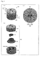
- Figs. 1(a) and 1(b) are sectional side views passing through a center of a fluid measurement apparatus according to a first embodiment
- Fig. 1(a) is a front view illustrating the section of the fluid measurement apparatus
- Fig. 1(b) is a perspective view illustrating the section of the fluid measurement apparatus.
- a configuration of a fluid measurement apparatus 100 according to a first embodiment will be described with reference to Figs. 2(a) to 2(c) .
- Fig. 2(a) is a perspective view of the fluid measurement apparatus 100
- Fig. 2(b) is an exploded view of the fluid measurement apparatus 100.
- the fluid measurement apparatus 100 having a substantially cylindrical outline includes an inflow and outflow unit 1031 in a whole azimuthal direction of a side surface thereof.
- a fluid flows in the fluid measurement apparatus 100 from an outside (external environment) through the inflow and outflow unit 1031, and the fluid flows out from the fluid measurement apparatus 100 to the outside.
- the fluid measurement apparatus 100 includes a detection element board 101 mounted on a detection element board mounting unit 102 and a control board 1041.
- An arithmetic unit 1042, a temperature and humidity sensor 1044 (temperature detector/humidity detector), and azimuth sensor 1045 (azimuth detector) are provided on the control board 1041.
- the temperature and humidity sensor 1044 is an element that detects temperature and humidity of the fluid
- the azimuth sensor 1045 is an element that detects absolute azimuths of the east, west, north, and south.
- the temperature and humidity sensor 1044 that detects the temperature and the humidity is provided in the first embodiment.
- a temperature sensor that detects only the temperature may be provided or a humidity sensor that detects only the humidity may be provided.
- the arithmetic unit 1042 is electrically connected to a detector 1043, the temperature and humidity sensor 1044, and the azimuth sensor 1045 to form a signal processing circuit 105 (see Fig. 10 ).
- the detector 1043 is arranged on the detection element board 101.
- the detector 1043 includes two detection elements 1043a and 1043b (detection element unit).
- Each of the detection elements 1043a and 1043b has a detection axis on which a flow rate is detected in one direction of the fluid contacting thereto.
- the detection elements 1043a and 1043b are arranged on the detection element board 101 while the detection axes thereof are orthogonal to each other. The velocity and the direction of the fluid can be seen from flow rate components that are detected in the directions of the detection axes by the detection elements 1043a and 1043b.
- the fluid measurement apparatus 100 of the invention can be said to be an anemometer.
- the anemometer includes an inflow unit (inflow and outflow unit 1031) that introduces a flow from a whole circumference direction and a flow rate detection element (detector 1043) that has sensitivity to at least a biaxial direction in order to detect a wind direction, and an outflow unit (inflow and outflow unit 1031) is identical to the inflow unit.
- Figs. 1(a) and 1(b) are sectional side views passing through a center of the fluid measurement apparatus 100.
- Fig. 1 (a) is a front view illustrating a section of the fluid measurement apparatus 100
- Fig. 1(b) is a perspective view illustrating the section of the fluid measurement apparatus 100.
- a channel for the fluid flowing in from the inflow and outflow unit 1031 is formed in the fluid measurement apparatus 100.
- the channel includes the inflow and outflow unit 1031, centrifugal separation channel units 1032a and 1032b, a detector channel unit 1033, and a bottom channel unit 1034.
- the centrifugal separation channel unit (centrifugal separation channel) 1032a is formed in an upper structure 103.
- the centrifugal separation channel unit (centrifugal separation channel) 1032b is formed between the upper structure 103 and a side surface of the detection element board mounting unit 102.
- the detector channel unit 1033 is formed between the upper structure 103 and the side surface of the detection element board mounting unit 102.
- the inflow and outflow unit 1031 is formed in a whole azimuthal direction in the side surface of the cylindrical fluid measurement apparatus 100.
- plural openings may be provided at equal intervals in the azimuthal direction, or a predetermined number of columns may be provided in a slit communicating in the whole azimuthal direction.
- Each of the centrifugal separation channel units 1032a and 1032b is a ring-like channel that is formed in a gap with two coaxial cylinders having different diameters as an inside surface and an outside surface.
- the outside surface and the inside surface have a center axis that passes perpendicularly through the detector 1043 (detection elements 1043a and 1043b).
- the ring-like diameter of the centrifugal separation channel unit 1032b is smaller than that of the centrifugal separation channel unit 1032a, and the centrifugal separation channel unit 1032b is formed inside the centrifugal separation channel unit 1032a so as to be parallel with the centrifugal separation channel unit 1032a.
- the centrifugal separation channel unit 1032a In an upper region of the outside surface of the centrifugal separation channel unit 1032a, the centrifugal separation channel unit 1032a communicates with the inflow and outflow unit 1031 in the whole azimuthal direction. In a lower region of the outside surface of the centrifugal separation channel unit 1032b, the centrifugal separation channel unit 1032b communicates with the lower region of the inside surface of the centrifugal separation channel unit 1032a in the whole azimuthal direction.
- the detector channel unit 1033 communicates with the upper region of the inside surface of the centrifugal separation channel unit 1032b in the whole azimuthal direction.
- the fluid measurement apparatus 100 can also be said to include an internal cylindrical channel (centrifugal separation channel units 1032a and 1032b) that is formed perpendicular to the inflow direction of the fluid and an internal channel structure in which the inflow is three-dimensionally split using the outside wall surface of the internal cylindrical channel and is partially introduced to the detector 1043.
- an internal cylindrical channel centrifugal separation channel units 1032a and 1032b
- the fluid measurement apparatus 100 can also be said to include an internal channel structure in which the inflow split using the outside wall surface of the internal cylindrical channel is further split using the inside wall surface of the internal cylindrical channel and is partially introduced to the detector 1043.
- the bottom channel unit 1034 communicates with the centrifugal separation channel units 1032a and 1032b in the whole azimuthal direction.
- the fluid can flow in and out from the inflow and outflow unit 1031 in the whole azimuthal direction.
- the fluid measurement apparatus 100 includes the centrifugal separation channel unit 1032a including a cylindrical channel that communicates with the inflow and outflow unit 1031 in the whole azimuthal direction.
- the fluid flowing in the centrifugal separation channel unit 1032a from the flowing inflow and outflow unit 1031 returns partially to the centrifugal separation channel unit 1032a through the detector channel unit 1033 and flows out from the inflow and outflow unit 1031.
- the inflow and outflow unit 1031 and the centrifugal separation channel unit 1032a have symmetrical structures in the whole azimuthal direction with respect to the center axis passing through the detector 1043. Accordingly, the fluid can be measured under the same condition at the whole azimuth.
- the fluid flowing in from the inflow and outflow unit 1031 in any azimuthal direction contacts partially with the detector 1043 through the centrifugal separation channel units 1032a and 1032b and the detector channel unit 1033. Accordingly, the detector 1043 can detect the velocity and the direction of the fluid in the whole azimuthal direction.
- the fluid flowing in the centrifugal separation channel unit 1032b flows partially in the detector channel unit 1033. Therefore, an amount of fluid flowing in the detector channel unit 1033 depends on a size of a conduction region between the centrifugal separation channel unit 1032b and the detector channel unit 1033.
- the detection elements 1043a and 1043b a velocity range where the velocity of the fluid can accurately be measured is fixed according to specifications. According to the configuration of the fluid measurement apparatus 100, using the same detection elements 1043a and 1043b, various velocity states of the external fluid can be dealt with by properly setting the size of the conduction region between the centrifugal separation channel unit 1032b and the detector channel unit 1033.
- the fluid flows in the fluid measurement apparatus 100 while constituting three flows w1 to w3 indicated by the arrows in Fig. 1 (a) .
- the fluid proceeds sequentially through the inflow and outflow unit 1031, the centrifugal separation channel unit 1032a, the centrifugal separation channel unit 1032b, the detector channel unit 1033, the centrifugal separation channel unit 1032b, the centrifugal separation channel unit 1032a, and the inflow and outflow unit 1031.
- the fluid proceeds sequentially through the inflow and outflow unit 1031, the centrifugal separation channel unit 1032a, the bottom channel unit 1034, the centrifugal separation channel unit 1032a, and the inflow and outflow unit 1031.
- the fluid proceeds sequentially through the inflow and outflow unit 1031, the centrifugal separation channel unit 1032a, and the inflow and outflow unit 1031.
- the fluid proceeds sequentially through the inflow and outflow unit 1031, the centrifugal separation channel units 1032a and 1032b, and the inflow and outflow unit 1031.
- part of the fluid flowing in the centrifugal separation channel unit 1032a from the inflow and outflow unit 1031 passes through the centrifugal separation channel unit 1032b and the detector channel unit 1033, passes through the centrifugal separation channel unit 1032b again, returns to the centrifugal separation channel unit 1032a, and flows out from the inflow and outflow unit 1031 (flow w1).
- the remaining fluid flows out from the inflow and outflow unit 1031 through the centrifugal separation channel units 1032a and 1032b and the bottom channel unit 1034 (flows w2, w3, and w4).
- the flows w1, w2, and w3 of the fluid in the fluid measurement apparatus 100 will be described in order.
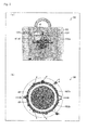
- Fig. 3(a) is a sectional view taken on a broken line A-A' in Fig. 2(a) .
- Fig. 3(b) is a sectional view taken on a broken line B-B' in Fig. 2(a) .
- the fluid flowing in from the inflow and outflow unit 1031 flows in the centrifugal separation channel unit 1032a.
- the fluid flowing perpendicularly downward reaches the connection unit between the centrifugal separation channel unit 1032a and the centrifugal separation channel unit 1032b and the bottom channel unit 1034 through the centrifugal separation channel unit 1032a.
- the fluid flowing horizontally (w3) flows along the circumferential direction of the ring shape of the centrifugal separation channel unit 1032a. Therefore, dust G existing in the fluid is subjected to a centrifugal force toward the outside of the ring, namely, the outside surface direction of the centrifugal separation channel unit 1032a.
- the dust G subjected to the centrifugal force is discharged from the inflow and outflow unit 1031 while flowing near the outside surface. Accordingly, the dust included in the fluid decreases (effect A).
- the fluid has both the flow rate component in the perpendicularly downward direction and the flow rate component in the horizontal direction. Therefore, the fluid flows horizontally while flowing perpendicularly downward in the centrifugal separation channel unit 1032a. Accordingly, the dust in the fluid decreases by the effect A while the fluid passes through the centrifugal separation channel unit 1032a.
- the flow rate direction of the fluid in which the dust decreases changes when the fluid flows in the centrifugal separation channel unit 1032b or the bottom channel unit 1034 from the centrifugal separation channel unit 1032a.
- the fluid having the large flow rate component in the perpendicularly upward direction flows in the centrifugal separation channel unit 1032b (flow w1).
- the fluid having the large flow rate component in the horizontal direction flows in the bottom channel unit 1034 (flow w2).
- an inertia force namely, a downward force acts on the dust in the fluid flowing in the centrifugal separation channel unit 1032b from the centrifugal separation channel unit 1032a (w1) by the change of the flow rate direction from the downward direction to the upward direction. Therefore, the dust flows easily in the bottom channel unit 1034, and flows hardly in the centrifugal separation channel unit 1032b. Accordingly, the dust included in the fluid flowing through the centrifugal separation channel unit 1032b (flow w1) decreases (effect B).
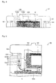
- Fig. 4 is an enlarged view illustrating a neighborhood of the detector channel unit 1033.
- the detector channel unit 1033 includes a disc-shaped central portion 1033a centered on the detector 1043 and a peripheral portion 1033b connected to the centrifugal separation channel unit 1032b.
- a channel area of the detector channel unit 1033 is narrowed from the peripheral portion 1033b toward the central portion 1033a. Therefore, the flow is expected to be stabilized near the detector 1043.
- the fluid flowing in the detector channel unit 1033 contacts with the detector 1043. At this point, in the fluid contacting with the detector 1043, the dust decreases by the effects A and B. Accordingly, generation of a fluid velocity detection error caused by adhesion of the dust to the detector 1043 can be constrained.
- the fluid contacting with the detector 1043 flows out from the inflow and outflow unit 1031 through the centrifugal separation channel units 1032b and 1032a.
- Fig. 5 is an enlarged view illustrating the neighborhood of the connection unit between the centrifugal separation channel units 1032a and 1032b and the bottom channel unit 1034 in the fluid measurement apparatus 100.
- the downward flow in the centrifugal separation channel unit 1032a changes to the upward flow in the centrifugal separation channel unit 1032b. Therefore, the downward inertia force acts on the dust in the fluid flowing in the centrifugal separation channel unit 1032b from the centrifugal separation channel unit 1032a. Particularly, when h is lower than a level of the bottom channel unit 1034, the inertia force acts on the dust G passing through the connection unit, thereby decreasing the dust G flowing in the centrifugal separation channel unit 1032b.
- the detector 1043 includes the two detection elements 1043a and 1043b that detect the flow rate as a voltage value. Generally a flow rate region having high measurement accuracy exists in the detection elements 1043a and 1043b.
- Fig. 6 is a graph illustrating an example of a relationship between the velocity (flow rate) of the fluid contacting with each of the detection elements 1043a and 1043b and an output voltage of each of the detection elements 1043a and 1043b.
- the detection accuracy of the flow rate is high because the output voltage changes largely with respect to the change in flow rate.
- the detection accuracy of the flow rate is low because the output voltage does not change largely with respect to the change in flow rate.
- the velocity of the fluid contacting with each of the detection elements 1043a and 1043b is included in the region where the detection accuracy of the flow rate is high, namely, an optimum flow rate sensitive region.
- various velocities of the fluids contact with the detection elements 1043a and 1043b depending on the flow rate of the external environment.
- the velocity of the fluid contacting with each of the detection elements 1043a and 1043b is included in the region where the detection accuracy of the flow rate is low. Therefore, in the conventional fluid measurement apparatus, the high detection accuracy of the flow rate cannot be maintained according to the external environments in which the flow rates differ from each other.
- a velocity vf ( Fig. 16(a) ) of the fluid contacting with the fluid detection element 802a (802b) at a gap d between the two fluid guide plates 801 a and 801 b is rarely different from a velocity vf' ( Fig. 16(b) ) of the fluid contacting with the fluid detection element 802a (802b) when the gap d is changed to d'.
- the conventional fluid detection device 800 cannot respond to the change in flow rate of the external environment by a simple design change.
- the flow rate in the centrifugal separation channel unit 1032b can be adjusted by the simple design change in which a channel area S1 of the centrifugal separation channel unit 1032a in Fig. 5 , a channel area S2 of the centrifugal separation channel unit 1032b, and a channel area S3 of the bottom channel unit 1034 are adjusted, and therefore the flow rate in the detector channel unit 1033 can easily be adjusted.
- the flow rate in the detector channel unit 1033 can be decreased by the design change such that a sum of S2 and S3 is increased with respect to S1 or such that a ratio of S2 to S3 is decreased.
- the flow rate of the fluid contacting with each of the detection elements 1043a and 1043b (detector 1043) can easily be adjusted so as to be included in the optimum flow rate sensitive region of the detection elements 1043a and 1043b (detector 1043) according to the flow rate of the external environment.
- the fluid measurement apparatus 100 can also be said to include the internal channel structure in which, by changing dimensions of the internal cylindrical channel (centrifugal separation channel units 1032a and 1032b), a split flow ratio is controlled to facilitate the adjustment of the flow rate of the fluid reaching the detector 1043.
- the two detection elements 1043a and 1043b constituting the detector 1043 are adjacent to each other in the channel direction while arranged on the detection element board 101.
- the detection elements 1043a and 1043b are arranged on the detection element board 101 a and 101 b with the channel interposed therebetween, and the detection elements 1043a and 1043b may be opposed to each other in the direction perpendicular to the channel direction.
- the detector 1043 can detect the correct direction of the fluid without generating the measurement error caused by a position shift between the two detection element units.
- the centrifugal separation channel units 1032a and 1032b are horizontally arrayed in parallel with each other. Accordingly, the channel is inverted and folded back at the connection unit between the centrifugal separation channel units 1032a and 1032b. At the connection unit, a turbulent flow is easily generated by the rapid change of the flow direction.
- a chamfer 1135 may be provided at the connection unit between the centrifugal separation channel units 1032a and 1032b in order to buffer the rapid change of the channel direction.
- part of the fluid flows along the chamfer 1135 from the centrifugal separation channel unit 1032a to change the flow direction, and the flow direction comes close to the direction of the centrifugal separation channel unit 1032b. Accordingly, the generation of the retaining flow and turbulent flow, which are caused by the rapid change of the channel direction, can be constrained.
- connection unit between the centrifugal separation channel units 1032a and 1032b in the detection element board mounting unit 102' and the connection unit between the centrifugal separation channel unit 1032b and the detector channel unit 1033 in the upper structure 103' may be formed into curved shaped. According to the configuration of the fluid measurement apparatus 100c, the flow of the fluid is stabilized because the generation of the retaining flow and the turbulent flow are constrained in the two connection units.
- Fig. 9(b) is a sectional view taken on a broken line C-C' in Fig. 9(a) . As indicated by arrows w1', w2', and w3' in Fig.
- part of the fluid flowing in from the inflow and outflow unit 1031 flows directly out from the inflow and outflow unit 1031 through the centrifugal separation channel unit 1032a (w1'), and different part of the fluid contacts with the detector 1043 through centrifugal separation channel units 1032a and 1032b and flows out from the inflow and outflow unit 1031 through the centrifugal separation channel units 1032b and 1032a (w2') again.
- the remaining fluid flows out from the inflow and outflow unit 1031 through the centrifugal separation channel units 1032a and 1032b (w3').
- Fig. 10 is a block diagram illustrating a configuration of the signal processing circuit 105.
- Voltage signals detected by the two detection elements 1043a and 1043b constituting the detector 1043 are transmitted to the arithmetic unit 1042 after an analog front-end adjusts the voltage signals.
- the arithmetic unit 1042 calculates the velocity and the direction of the fluid in the channel from the voltage signals.
- the arithmetic unit 1042 performs processing of converting a calculation result into the velocity and the direction of the fluid in the external environment according to the channel design, and output the velocity and the direction of the fluid in the external environment to the outside.
- the arithmetic unit 1042 may acquire temperature and humidity information on the external environment from the temperature and humidity sensor 1044.
- the arithmetic unit 1042 may output, as data, a comfort index (PMV (Predicted Mean Vote), SET* (Standard new Effective Temperature)), and a heat stroke risk calculated from the information on the velocity and the direction of the fluid and the temperature and humidity information.
- PMV Predicted Mean Vote
- SET* Standard new Effective Temperature
- the arithmetic unit 1042 may acquire absolute azimuth information from the azimuth sensor 1045, correct information on the fluid direction acquired from the detector 1043 into the direction based on an absolute azimuth, and output the corrected information on the fluid direction.
- the detector 1043 includes the two detection elements 1043a and 1043b.
- the detection elements 1043a and 1043b are arranged on the detection element board 101 while the detection axis direction of the detection elements 1043a and 1043b are orthogonal to each other in a plane of the channel direction.
- Each of the detection elements 1043a and 1043b can detect the flow rate in one direction (detection axis direction).
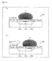
- a principle detecting the fluid velocity with the detection elements 1043a and 1043b will be described with reference to Figs. 11 (a) and 11 (b) .
- a detection element 1043' in Figs. 11 (a) and 11(b) may be regarded as any one of the detection elements 1043a and 1043b.
- the detection element 1043' includes two thermopiles 1101a and 1101b and a heater element 1102.
- the thermopile 1101a, the heater element 1102, and the thermopile 1101b are arrayed in line along the channel.
- the array direction is the detection axis direction of the detection element 1043'.
- the heater element 1102 radiates heat to form a thermal distribution of the fluid in the channel.
- Fig. 11 (a) illustrates a thermal distribution T1 in a state in which the fluid is held still in the channel.
- the thermal distribution T1 has a symmetry in the detection axis direction with respect to the heater element 1102.
- the thermopiles 1101 a and 1101 b detect the temperatures at the positions where the thermopiles 1101a and 1101b are arranged as voltage values. Accordingly, for example, in the case that a distance from the thermopile 1101a to the heater element 1102 is equal to a distance from the thermopile 1101 b to the heater element 1102, the temperatures detected by the thermopiles 1101a and 1101b are equal to each other because the thermal distribution T1 has the symmetry in the detection axis direction.
- Fig. 11(b) illustrates a thermal distribution T2 in a state in which the flow exist in the channel.
- the thermal distribution T2 loses the symmetry in the detection axis direction because the flow exists in the arrow direction. Therefore, the temperatures detected by the thermopiles 1101a and 1101b differ from those in the still state of the fluid.
- the thermal distribution varies in the case that the flow rate varies while the fluid flows. Accordingly, when a relationship between the flow rate and the thermal distribution is previously checked, the flow rate can be detected by the temperatures detected by the thermopiles 1101 a and 1101b.
- thermopile 1101 a and 1101 b a difference in flow rate is detected as the temperatures detected by the thermopile 1101 a and 1101 b.
- the detection element 1043' acquires the temperatures detected by the thermopiles 1101 a and 1101b as a voltage difference ⁇ V between the output voltages of the thermopiles.
- Th is a temperature at the heater element 1102
- Ta is a temperature in the external environment
- a and b are constants.
- the flow rate Vf in the detection axis direction is detected by the detection element 1043'.
- the detector 1043 acquires the flow rates in the detection axis directions, namely, the flow rate components orthogonal to each other from the detection elements 1043a and 1043b in which the detection axis directions are orthogonal to each other, thereby detecting the velocity and the direction of the fluid.
- a fluid measurement apparatus according to a second embodiment of the invention will be described below with reference to Fig. 12 .
- the component similar to that of the first embodiment is designated by the same symbol, and the description is neglected.
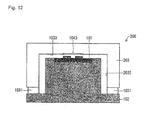
- Fig. 12 is a schematic diagram illustrating a fluid measurement apparatus 200 of the second embodiment.
- the fluid measurement apparatus 200 differs from the fluid measurement apparatus 100 of the first embodiment in that the fluid measurement apparatus 200 includes one centrifugal separation channel unit (centrifugal separation channel) 2032.
- the fluid measurement apparatus 100 includes the two centrifugal separation channel units 1032a and 1032b. Therefore, a shape of an upper structure 203 of the fluid measurement apparatus 200 differs from that of the upper structure 103. Because of the difference of the configuration, the fluid channel of the fluid measurement apparatus 200 differs from that of the fluid measurement apparatus 100.
- the channel of the fluid measurement apparatus 200 will be described below.
- the fluid flowing in the fluid measurement apparatus 200 flows therein while forming two flows.
- the fluid proceeds sequentially through the inflow and outflow unit 1031, a centrifugal separation channel unit 2032, the detector channel unit 1033, a centrifugal separation channel unit 2032, and the inflow and outflow unit 1031.
- the fluid proceeds sequentially through the inflow and outflow unit 1031, the centrifugal separation channel unit 2032, and the inflow and outflow unit 1031.
- the centrifugal separation channel unit 2032 is a ring channel that is formed in a gap between the inside surface and the outside surface of the two coaxial cylinders having the different diameters. In the outside surface and the inside surface, the perpendicular axis passing through the detector 1043 is used as the center axis. In the outside surface, the centrifugal separation channel unit 2032 communicates with the inflow and outflow unit 1031 in the whole azimuthal direction.
- the centrifugal separation channel unit 2032 communicates with the inflow and outflow unit 1031 in the whole azimuthal direction.
- the detector channel unit 1033 communicates with the upper region of the inside surface of the centrifugal separation channel unit 2032 in the whole azimuthal direction.
- the fluid flowing in from the inflow and outflow unit 1031 flows partially out from the inflow and outflow unit 1031 through the centrifugal separation channel unit 2032, the detector channel unit 1033, and the centrifugal separation channel unit 2032. The remaining fluid flows directly out through the centrifugal separation channel unit 2032.
- the fluid passing through the centrifugal separation channel unit 2032 flows along the ring-like circumferential direction, and is subjected to the centrifugal force toward the outside of the circumference, namely, the outside surface direction of the centrifugal separation channel unit 2032. Because the dust G subjected to the centrifugal force is discharged from the inflow and outflow unit 1031 to the outside while flowing near the outside surface, the dust included in the fluid decreases. Because the dust that is not discharged to the outside flows along the outside surface of the centrifugal separation channel unit 2032, almost the dust does not flow in the detector channel unit 1033.
- the fluid measurement apparatus 200 has the configuration simpler than the fluid measurement apparatus 100, the dust hardly adheres to the detector 1043.
- the velocity of the fluid flowing in the detector channel unit 1033 can be controlled by adjusting a ratio between the channel area of the detector channel unit 1033 and the channel area of the centrifugal separation channel unit 2032.
- the component of the control board 1041 on which the arithmetic unit 1042 is arranged may be identical to that of the detection element board 101.
- the temperature and humidity sensor and the azimuth sensor may be arranged on the detection element board 101.
- a fluid measurement apparatus according to a third embodiment of the invention will be described below with reference to Figs. 13(a) to 13(c) .
- the component similar to that of the first and second embodiments is designated by the same symbol, and the description is neglected.
- Figs. 13(a) and 13(b) are schematic diagrams of fluid measurement apparatuses 300 and 300a of the third embodiment.
- Figs. 13(a) illustrates a configuration example in which one centrifugal separation channel unit (centrifugal separation channel) 3032 is included
- Fig. 13(b) illustrates a configuration in which two centrifugal separation channel units (centrifugal separation channels) 3032a and 3032b are included.
- connection unit between the inflow and outflow unit 1031 and the centrifugal separation channel unit 3032a are located in a central region of the outside surface of the centrifugal separation channel unit 3032 (3032a) with respect to the center axis direction.
- Fig. 13(c) is a schematic diagram illustrating a fluid measurement apparatus 900 of a reference.
- the fluid measurement apparatus 900 differs from the fluid measurement apparatus 300 (300a) in that the position where the inflow and outflow unit 1031 and the centrifugal separation channel unit 9032a communicate with each other is located in the upper region of the outside surface of the centrifugal separation channel unit 9032a (an end region different from the lower region connected to the centrifugal separation channel unit 9032b).
- the fluid flow in the fluid measurement apparatus 300 (300a) will be described below in comparison with that of the fluid measurement apparatus 900.
- a large part of the fluid flowing in from the inflow and outflow unit 1031 flows in the horizontal direction.
- a main flow direction of the fluid flowing in from the inflow and outflow unit 1031 is the horizontal direction. This is because the inflow and outflow unit 1031 is provided in the perpendicular side surface of each of the fluid measurement apparatuses 300, 300a, and 900.
- the amount of fluid flowing in the horizontal direction is larger than that of the fluid measurement apparatus 900.
- the fluid flowing in horizontally from the inflow and outflow unit 1031 flows in the region surrounded by the upper side surface and the inside surface of the centrifugal separation channel unit 9032a.
- the main flow direction of the fluid becomes an obliquely downward direction along the ring-like shape of the centrifugal separation channel unit 9032a by a resultant force of reaction in the upper side surface and the inside surface.
- the fluid flowing in from the inflow and outflow unit 1031 is subjected only to the reaction from the inside surface of the centrifugal separation channel unit 9032a, but the reaction is not generated in the vertical direction. That is, because the perpendicular component of the flow rate does not change, the main flow direction of the fluid exists on a horizontal plane that is substantially flush with the inflow and outflow unit 1031 along the ring-like shape of the centrifugal separation channel unit 9032a.
- the dust included in the fluid (main flow) flowing along the ring-like shape flows near the outside surface of the centrifugal separation channel unit 3032 (3032a) by the centrifugal force. Because the inflow and outflow unit 1031 is provided in the outside surface on the horizontal plane of the flowing direction, the dust is discharged to the outside from the inflow and outflow unit 1031. Accordingly, the dust included in the fluid decreases.
- the fluid measurement apparatus 300 (300a) has the configuration in which the dust is easily discharged from the inflow and outflow unit 1031 because the inflow and outflow unit 1031 exists on the horizontal surface flush with the main flow direction in which the flow rate of the fluid is the highest. Accordingly, the effect that the dust does not adhere to the detector 1043 is enhanced.
- the inflow and outflow unit 1031 is provided near the center in the height direction of the fluid measurement apparatus 300 (300a).
- the configuration of the fluid measurement apparatus 300 (300a) has the high external symmetry in the vertical direction. Therefore, there is a small difference of a fluid inflow amount between the flow rate components in the vertical direction of the fluid.
- the error caused by the change of the amount of fluid flowing in according to an incident angle of the fluid in the vertical direction with respect to the inflow and outflow unit 1031 can be constrained from being generated in the measured value of the flow rate.
- the inflow and outflow unit 1031 is provided at the central position in the outside surface of the centrifugal separation channel unit 3032 (3032a), the outside surface extends vertically with respect to the level at which the inflow and outflow unit 1031 is provided. Accordingly, the inflow and outflow unit 1031 is easily provided near the center in the height direction of the fluid measurement apparatus 300 (300a).
- an additional structure 903a is provided on the top of the upper structure 103 in order to enhance the external symmetry in the vertical direction.
- a fluid measurement apparatus of the invention includes: a detector configured to detect at least one of a fluid velocity and a fluid direction by contacting with the fluid; an inflow and outflow unit provided on a circumference of a circle having a center on a predetermined center axis, the fluid flowing in the inflow and outflow unit from an outside of the fluid measurement apparatus and flowing out from the inflow and outflow unit to the outside of the fluid measurement apparatus; a centrifugal separation channel including a ring channel centered on the center axis, and configured to communicate with the inflow and outflow unit by a connection unit provided on a circumference parallel to the ring channel; and a detector channel configured to communicate with the centrifugal separation channel by a connection unit provided on a circumference parallel to the centrifugal separation channel, the detector being provided at a position passing through the center axis.
- the fluid measurement apparatus includes the inflow and outflow unit and the centrifugal separation channel.
- the fluid flows in the inflow and outflow unit provided on the circumference of the circle and flows out from the inflow and outflow unit.
- the centrifugal separation channel communicates with the inflow and outflow unit by the connection unit provided on the circumference parallel to the channel.
- the dust included in the fluid flowing in the centrifugal separation channel constructed with the ring channel is subjected to the centrifugal force in the centrifugal separation channel, and flows in the region near the ring outside surface. Accordingly, because the amount of dust included in the fluid flowing through the detector channel can be constrained, the dust hardly adheres to the detector.
- the inflow and outflow unit, the connection unit between the inflow and outflow unit and the centrifugal separation channel, and the connection unit between the centrifugal separation channel and the detector channel are provided on the circumference. Accordingly, a configuration can be made in which the inflow and the outflow of the fluid are not affected by the fluid flowing direction. That is, one of the velocity and the direction of the fluid can be detected irrespective of the influence of the fluid flowing direction.
- part of the fluid flowing in centrifugal separation channel flows in the detector channel. Therefore, the amount of fluid flowing in the detector channel depends on the size of the conduction region between the centrifugal separation channel and the detector channel.
- the velocity range where the velocity of the fluid can accurately be measured is fixed according to the specifications of the element. That is, according to the configuration, using the same element of the detector, a fluid measurement apparatus can be provided in which various velocity states of the external fluid can be dealt with by properly setting the size of the conduction region between the centrifugal separation channel and the detector channel.
- the detector may include plural detection element units as described later.
- the region of the detector includes the region where the plural detection element units are arranged.
- the detector is provided at the position passing through the center axis.
- the detector channel may communicate with the centrifugal separation channel in an inside surface that is of a surface located on a center axis side in surfaces constituting the centrifugal separation channel.
- the detector channel communicates with the centrifugal separation channel in the inside surface of the centrifugal separation channel.
- the direction in which the dust in the fluid is separated from the fluid is the direction of the outside surface of the centrifugal separation channel. Therefore, a smaller amount of dust is included in the fluid flowing in the detector channel. Accordingly, the dust can be prevented from adhering to the detector.
- the inflow and outflow unit may communicate with the centrifugal separation channel in an outside surface that is of a surface located on an opposite side with respect to the center axis in the surfaces constituting the centrifugal separation channel.
- the inflow and outflow unit communicates with the centrifugal separation channel in the outside surface of the centrifugal separation channel that is of the direction in which the dust is subjected to the centrifugal force. Therefore, the dust moving to the outside surface is discharged to the outside from the inflow and outflow unit. Accordingly, the clean channel can be maintained.
- the detector may include two detection element units configured to detect the fluid velocity in an uniaxial direction, the two detection element units may be arranged such that axes on each of which the fluid velocity in the uniaxial direction is detected are orthogonal to each other, and the two detection element units may be opposed to each other in a direction perpendicular to a direction of the detector channel.
- the two detection element units are arranged such that the axes on each of which the fluid velocity is detected are orthogonal to each other. Therefore, the two detection elements can detect the orthogonal components of the velocity and the direction of the fluid.
- the two detection element units constituting the detector detects the velocity in the uniaxial direction of the fluid, and the detection element units are opposed to each other in the direction perpendicular to the channel direction. Therefore, the two detection element units can detect the fluid velocity at the same position in the fluid flowing direction. Accordingly, the detector can correctly detect the velocity and the direction of the fluid without generating the measurement error caused by the position shift between the two detection element units.
- the detector may include two detection element units configured to detect the fluid velocity in an uniaxial direction, the two detection element units may be arranged such that axes on each of which the fluid velocity in the uniaxial direction is detected are orthogonal to each other, and the two detection element units may be located on an identical side with respect to the detector channel while being adjacent to each other in a direction of the detector channel.
- the two detection element units are arranged such that the axes on each of which the fluid velocity is detected are orthogonal to each other. Therefore, the two detection elements can detect the orthogonal components of the fluid velocity.
- the two detection element units are provided on the same side with respect to the detector channel. Therefore, electric wirings connected to the two detection element units can be provided on the same side with respect to the detector channel. Accordingly, routing of the electric wiring can be facilitated.
- the centrifugal separation channel may include plural ring channels having radii different from each other.
- the plural ring channels included in the centrifugal separation channel have the radii different from each other.
- the ring channel having the large radius has a long channel length in the ring portion thereof, and the ring channel having the small radius has a large curvature. Accordingly, the ring channel having the large radius can separate a large amount of dust.
- the centrifugal force acts strongly on the fluid and dust, which pass through the ring portion thereof. Therefore, not only the heavy dust but also the small, light dust can be separated.
- a throttle may be provided in the detector channel in order to reduce a sectional area of the detector channel at the position where the fluid contacts with the detector compared with sectional areas of the detector channel at other positions.
- the sectional area (channel area) of the detector channel is reduced at the position contacting with the detector by the throttle of the detector channel. Therefore, the flow of the fluid is stabilized at the position contacting with the detector. Accordingly, the detector can correctly detect the velocity and the direction of the fluid.
- the inflow and outflow unit may communicate with the centrifugal separation channel in a central region in the center axis direction in the outside surface that is of the opposite surface with respect to the center axis in the surfaces constituting the centrifugal separation channel.
- the main stream direction of the fluid flowing from the inflow and outflow unit exist on a horizontal plane perpendicular to the center axis direction in the centrifugal separation channel. That is, the dust is easily discharged from the inflow and outflow unit because the inflow and outflow unit exists on the horizontal surface flush with the main flow direction in which the flow rate of the fluid is the highest.
- At least one of corner portions in an outline of the connection unit in which the different channels communicate with each other may be chamfered or rounded by a curved shape in a planar section including the center axis.
- the flow of the fluid passing through the connection unit is stabilized. Accordingly, the changes in velocity and direction of the fluid can be constrained in the connection unit.
- a user of the fluid measurement apparatus wants to know the velocity and the direction of the fluid in the external environment of the fluid measurement apparatus.
- the fluid measurement apparatus of the invention may further include an arithmetic unit configured to acquire data of the fluid velocity and the fluid direction from the detector, perform an operation to the data, and output the fluid velocity and the fluid direction in an external environment.
- the fluid direction in the external environment can be detected based on the absolute azimuth irrespective of the direction of the fluid measurement apparatus.
- the fluid measurement apparatus of the invention may further include an azimuth detector configured to detect an absolute azimuth.
- the arithmetic unit may output an absolute-azimuth-based direction as the fluid direction in the external environment based on the absolute azimuth detected by the azimuth detector and the fluid direction detected by the detector.
- the fluid measurement apparatus of the invention may further include at least one of a temperature detector configured to detect a temperature of the fluid and a humidity detector configured to detect humidity of the fluid.
- the arithmetic unit may perform an operation based on at least one of pieces of data of the detected temperature and humidity and pieces of data of the fluid velocity and the fluid direction, and output index data of an environmental state.
- index data of the environmental state such as a comfort level of the external environment can be provided to the user based on at least one of the temperature and the humidity of the fluid and the velocity and the direction of the fluid.
- the invention can be applied to the fluid measurement apparatus that detects the velocity and the direction of the fluid.
- the invention can be used for monitoring of a down flow in a clean room, monitoring of airflow in a data center, monitoring of air conditioning and amenity in a factory of a workplace, and monitoring of air conditioning, a ventilation state, and amenity in a home.
Landscapes
- Physics & Mathematics (AREA)
- General Physics & Mathematics (AREA)
- Engineering & Computer Science (AREA)
- Aviation & Aerospace Engineering (AREA)
- Indicating Or Recording The Presence, Absence, Or Direction Of Movement (AREA)
Abstract
Description
- The present invention relates to a fluid measurement apparatus that detects at least one of a velocity and a direction of a fluid.
- Conventionally, a detector that detects at least one of the velocity and the direction of the fluid by contacting directly with the fluid of a measurement target is provided in a fluid measurement apparatus. The detector includes a heater and a temperature sensor, and the temperature sensor measures a change in temperature distribution due to movement of the fluid heated by the heater, thereby detecting at least one of the velocity and the direction of the fluid.
- For example, in an anemoscope disclosed in
Patent Document 1, a micro flow sensor that detects the velocity of air flowing between two current plates is arranged in an inside surface of one of the current plates. Therefore, the air in which disturbance of an air flow is constrained flows in the micro flow sensor. - As illustrated in
Figs. 14(a) and 14(b) , in afluid detection device 800 disclosed in Patent Document 2, twofluid detection elements fluid guide plates - At this point, the target fluid in which the flow rate is detected is air as described in
Patent Document 1, and dust is included in the fluid depending on an environment. For example, in thefluid detection device 800 of Patent Document 2, as illustrated inFig. 15 , dust G included in the fluid adheres tofluid detection element 802a (802b) that detects the flow rate, and possibly thefluid detection element 802a (802b) is contaminated (Fig. 15 ). When thefluid detection element 802a (802b) is contaminated, detection performance degradation such as output sensitivity abnormality is possibly generated. The problem is generated in both the configuration ofPatent Documents 1 and 2. - Therefore, as illustrated in
Fig. 17 , Patent Document 3 discloses aflow measuring device 700 includingcentrifugal separation chambers introduction channels centrifugal separation chambers centrifugal separation chambers detection element 703. Accordingly, thedetection element 703 has a structure which the dust hardly adheres to or is hardly deposited on. -
- Patent Document 1: Japanese Unexamined Patent Publication No.
2011-128105 - Patent Document 2: Japanese Unexamined Patent Publication No.
4-295768 - Patent Document 3: Japanese Unexamined Patent Publication No.
2007-3387 - In the fluid measurement apparatus that measures the fluid velocity, sometimes at least one of the velocity and the direction of the fluid is desirably detected irrespective of an influence of a fluid flowing direction due to the detection target fluid. For example, in a general air environment, at least one of the velocity and the direction of the air flow (wind) is acquired to monitor a ventilation state and amenity of the air.
- In the configurations disclosed in
Patent Documents 1 and 2, the velocity and the direction of the fluid can be detected in a whole azimuth. However, as described above, there is the problem in that the dust adheres to and is deposition on the detector (a fluid detection element and a micro flow sensor). On the other hand, Patent Document 3 has the structure in which the dust hardly adheres to or is hardly deposited on the detector (detection element). However, the velocity and the direction of the fluid cannot be detected in the whole azimuth. This is because the flow measuring device of Patent Document 3 includes only two introduction channels and the fluid flows only in two directions. - The present invention has been made in view of the above problems, and an object of the invention is to provide a fluid measurement apparatus that can detect at least one of the velocity and the direction of the fluid irrespective of the influence of the fluid flowing direction and can constrain the dust in the fluid from adhering to the detector.
- To solve the above problems, in accordance with one aspect of the invention, a fluid measurement apparatus includes: a detector configured to detect at least one of a fluid velocity and a fluid direction by contacting with the fluid; an inflow and outflow unit provided on a circumference of a circle having a center on a predetermined center axis, the fluid flowing in the inflow and outflow unit from an outside of the fluid measurement apparatus and flowing out from the inflow and outflow unit to the outside of the fluid measurement apparatus; a centrifugal separation channel including a ring channel centered on the center axis, and configured to communicate with the inflow and outflow unit by a connection unit provided on a circumference parallel to the ring channel; and a detector channel configured to communicate with the centrifugal separation channel by a connection unit provided on a circumference parallel to the centrifugal separation channel, the detector being provided at a position passing through the center axis.
- As described above, the fluid measurement apparatus of the invention includes: the detector configured to detect at least one of the fluid velocity and the fluid direction by contacting with the fluid; the inflow and outflow unit provided on the circumference of the circle having the center on the predetermined center axis, the fluid flowing in the inflow and outflow unit from the outside of the fluid measurement apparatus and flowing out from the inflow and outflow unit to the outside of the fluid measurement apparatus; the centrifugal separation channel including the ring channel centered on the center axis, and configured to communicate with the inflow and outflow unit by the connection unit provided on the circumference parallel to the ring channel; and the detector channel configured to communicate with the centrifugal separation channel by the connection unit provided on the circumference parallel to the centrifugal separation channel, the detector being provided at the position passing through the center axis.
- Therefore, advantageously at least one of the velocity and the direction of the fluid can be detected irrespective of the influence of the fluid flowing direction, and the dust in the fluid can be constrained from adhering to the detector.
-
Figs. 1(a) and 1(b) are sectional side views passing through a center of a fluid measurement apparatus according to a first embodiment,Fig. 1(a) is a front view illustrating the section of the fluid measurement apparatus, andFig. 1(b) is a perspective view illustrating the section of the fluid measurement apparatus. -
Fig. 2(a) is a perspective view of a fluid measurement apparatus of the first embodiment,Fig. 2(b) is an exploded view of the fluid measurement apparatus, andFig. 2(c) is a view illustrating a configuration of a detector included in the fluid measurement apparatus. -
Fig. 3(a) is a sectional view taken on a broken line A-A' inFig. 2(a) , andFig. 3(b) is a sectional view taken on a broken line B-B' inFig. 2(a) . -
Fig. 4 is an enlarged view illustrating a neighborhood of a detector channel unit in the fluid measurement apparatus of the first embodiment. -
Fig. 5 is an enlarged view illustrating a neighborhood of a connection unit between a centrifugal separation channel unit and a bottom channel unit in the fluid measurement apparatus of the first embodiment. -
Fig. 6 is a graph illustrating an example of a relationship between a velocity of a fluid contacting with a detection element and an output voltage of the detection element. -
Fig. 7 is a schematic diagram illustrating a modification of the fluid measurement apparatus of the first embodiment. -
Fig. 8 is a schematic diagram illustrating a configuration of another modification of the fluid measurement apparatus of the first embodiment. -
Fig. 9(a) is a schematic diagram illustrating a configuration of still another modification of the fluid measurement apparatus of the first embodiment, andFig. 9(b) is a sectional view taken on a broken line C-C' inFig. 9(a) . -
Fig. 10 is a block diagram illustrating a configuration of a signal processing circuit formed in the fluid measurement apparatus of the first embodiment. -
Figs. 11 (a) and 11 (b) are views illustrating a configuration of a detection element. -
Fig. 12 is a schematic diagram of a fluid measurement apparatus according to a second embodiment. -
Figs. 13(a) and 13(b) are schematic diagrams of a fluid measurement apparatus according to a third embodiment, andFig. 13(c) is a schematic diagram of a fluid measurement apparatus of a reference. -
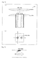
Fig. 14(a) is a view illustrating a configuration of a conventional fluid measurement apparatus, andFig. 14(b) is a view illustrating an arrangement of a detection element in the conventional fluid measurement apparatus. -
Fig. 15 is a schematic diagram illustrating a neighborhood of the detection element in the conventional fluid measurement apparatus. -
Figs. 16(a) and 16(b) are schematic diagrams illustrating the neighborhood of the detection element in the conventional fluid measurement apparatus. -
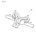
Fig. 17 is a view illustrating a configuration of another conventional fluid measurement apparatus. - Hereinafter, an exemplary embodiment of the invention will be described in detail with reference to
Figs. 1 to 13 . Unless otherwise noted, the scope of the invention is not limited to dimensions, a material, a shape, and a relative arrangement of a component described in each embodiment, but those are described only by way of example. - A configuration of a
fluid measurement apparatus 100 according to a first embodiment will be described with reference toFigs. 2(a) to 2(c) . -
Fig. 2(a) is a perspective view of thefluid measurement apparatus 100, andFig. 2(b) is an exploded view of thefluid measurement apparatus 100. - As illustrated in
Fig. 2(a) , thefluid measurement apparatus 100 having a substantially cylindrical outline includes an inflow andoutflow unit 1031 in a whole azimuthal direction of a side surface thereof. A fluid flows in thefluid measurement apparatus 100 from an outside (external environment) through the inflow andoutflow unit 1031, and the fluid flows out from thefluid measurement apparatus 100 to the outside. - As illustrated in
Fig. 2(b) , thefluid measurement apparatus 100 includes adetection element board 101 mounted on a detection elementboard mounting unit 102 and acontrol board 1041. - An
arithmetic unit 1042, a temperature and humidity sensor 1044 (temperature detector/humidity detector), and azimuth sensor 1045 (azimuth detector) are provided on thecontrol board 1041. The temperature and humidity sensor 1044 is an element that detects temperature and humidity of the fluid, and the azimuth sensor 1045 (digital compass) is an element that detects absolute azimuths of the east, west, north, and south. - The temperature and humidity sensor 1044 that detects the temperature and the humidity is provided in the first embodiment. Alternatively, a temperature sensor that detects only the temperature may be provided or a humidity sensor that detects only the humidity may be provided.
- The
arithmetic unit 1042 is electrically connected to adetector 1043, the temperature and humidity sensor 1044, and the azimuth sensor 1045 to form a signal processing circuit 105 (seeFig. 10 ). - As illustrated in
Fig. 2(c) , thedetector 1043 is arranged on thedetection element board 101. Thedetector 1043 includes twodetection elements detection elements detection elements detection element board 101 while the detection axes thereof are orthogonal to each other. The velocity and the direction of the fluid can be seen from flow rate components that are detected in the directions of the detection axes by thedetection elements - Accordingly, the
fluid measurement apparatus 100 of the invention can be said to be an anemometer. The anemometer (fluid measurement apparatus 100) includes an inflow unit (inflow and outflow unit 1031) that introduces a flow from a whole circumference direction and a flow rate detection element (detector 1043) that has sensitivity to at least a biaxial direction in order to detect a wind direction, and an outflow unit (inflow and outflow unit 1031) is identical to the inflow unit. -
Figs. 1(a) and 1(b) are sectional side views passing through a center of thefluid measurement apparatus 100.Fig. 1 (a) is a front view illustrating a section of thefluid measurement apparatus 100, andFig. 1(b) is a perspective view illustrating the section of thefluid measurement apparatus 100. - As indicated by arrows in
Fig. 1(a) , a channel for the fluid flowing in from the inflow andoutflow unit 1031 is formed in thefluid measurement apparatus 100. The channel includes the inflow andoutflow unit 1031, centrifugalseparation channel units detector channel unit 1033, and abottom channel unit 1034. - As illustrated in
Figs. 1(a) and 1(b) , the centrifugal separation channel unit (centrifugal separation channel) 1032a is formed in anupper structure 103. The centrifugal separation channel unit (centrifugal separation channel) 1032b is formed between theupper structure 103 and a side surface of the detection elementboard mounting unit 102. Thedetector channel unit 1033 is formed between theupper structure 103 and the side surface of the detection elementboard mounting unit 102. - The inflow and
outflow unit 1031 is formed in a whole azimuthal direction in the side surface of the cylindricalfluid measurement apparatus 100. In the inflow andoutflow unit 1031, plural openings may be provided at equal intervals in the azimuthal direction, or a predetermined number of columns may be provided in a slit communicating in the whole azimuthal direction. - Each of the centrifugal
separation channel units detection elements separation channel unit 1032b is smaller than that of the centrifugalseparation channel unit 1032a, and the centrifugalseparation channel unit 1032b is formed inside the centrifugalseparation channel unit 1032a so as to be parallel with the centrifugalseparation channel unit 1032a. - In an upper region of the outside surface of the centrifugal
separation channel unit 1032a, the centrifugalseparation channel unit 1032a communicates with the inflow andoutflow unit 1031 in the whole azimuthal direction. In a lower region of the outside surface of the centrifugalseparation channel unit 1032b, the centrifugalseparation channel unit 1032b communicates with the lower region of the inside surface of the centrifugalseparation channel unit 1032a in the whole azimuthal direction. Thedetector channel unit 1033 communicates with the upper region of the inside surface of the centrifugalseparation channel unit 1032b in the whole azimuthal direction. - That is, the
fluid measurement apparatus 100 can also be said to include an internal cylindrical channel (centrifugalseparation channel units detector 1043. - The
fluid measurement apparatus 100 can also be said to include an internal channel structure in which the inflow split using the outside wall surface of the internal cylindrical channel is further split using the inside wall surface of the internal cylindrical channel and is partially introduced to thedetector 1043. - In the lower regions of the centrifugal
separation channel units bottom channel unit 1034 communicates with the centrifugalseparation channel units - Thus, the fluid can flow in and out from the inflow and
outflow unit 1031 in the whole azimuthal direction. - The
fluid measurement apparatus 100 includes the centrifugalseparation channel unit 1032a including a cylindrical channel that communicates with the inflow andoutflow unit 1031 in the whole azimuthal direction. The fluid flowing in the centrifugalseparation channel unit 1032a from the flowing inflow andoutflow unit 1031 returns partially to the centrifugalseparation channel unit 1032a through thedetector channel unit 1033 and flows out from the inflow andoutflow unit 1031. - In the
fluid measurement apparatus 100, the inflow andoutflow unit 1031 and the centrifugalseparation channel unit 1032a have symmetrical structures in the whole azimuthal direction with respect to the center axis passing through thedetector 1043. Accordingly, the fluid can be measured under the same condition at the whole azimuth. The fluid flowing in from the inflow andoutflow unit 1031 in any azimuthal direction contacts partially with thedetector 1043 through the centrifugalseparation channel units detector channel unit 1033. Accordingly, thedetector 1043 can detect the velocity and the direction of the fluid in the whole azimuthal direction. - The fluid flowing in the centrifugal
separation channel unit 1032b flows partially in thedetector channel unit 1033. Therefore, an amount of fluid flowing in thedetector channel unit 1033 depends on a size of a conduction region between the centrifugalseparation channel unit 1032b and thedetector channel unit 1033. On the other hand, in thedetection elements fluid measurement apparatus 100, using thesame detection elements separation channel unit 1032b and thedetector channel unit 1033. - The channel and the flow of the fluid in the
fluid measurement apparatus 100 will be described below with reference toFigs. 1(a) and 1(b) ,3(a) and 3(b) , and4 . - The fluid flows in the
fluid measurement apparatus 100 while constituting three flows w1 to w3 indicated by the arrows inFig. 1 (a) . In the first flow w1, the fluid proceeds sequentially through the inflow andoutflow unit 1031, the centrifugalseparation channel unit 1032a, the centrifugalseparation channel unit 1032b, thedetector channel unit 1033, the centrifugalseparation channel unit 1032b, the centrifugalseparation channel unit 1032a, and the inflow andoutflow unit 1031. In the second flow w2, the fluid proceeds sequentially through the inflow andoutflow unit 1031, the centrifugalseparation channel unit 1032a, thebottom channel unit 1034, the centrifugalseparation channel unit 1032a, and the inflow andoutflow unit 1031. In the third flow w3, the fluid proceeds sequentially through the inflow andoutflow unit 1031, the centrifugalseparation channel unit 1032a, and the inflow andoutflow unit 1031. In the fourth flow w4, the fluid proceeds sequentially through the inflow andoutflow unit 1031, the centrifugalseparation channel units outflow unit 1031. In other words, part of the fluid flowing in the centrifugalseparation channel unit 1032a from the inflow andoutflow unit 1031 passes through the centrifugalseparation channel unit 1032b and thedetector channel unit 1033, passes through the centrifugalseparation channel unit 1032b again, returns to the centrifugalseparation channel unit 1032a, and flows out from the inflow and outflow unit 1031 (flow w1). On the other hand, the remaining fluid flows out from the inflow andoutflow unit 1031 through the centrifugalseparation channel units - The flows w1, w2, and w3 of the fluid in the
fluid measurement apparatus 100 will be described in order. -
Fig. 3(a) is a sectional view taken on a broken line A-A' inFig. 2(a) .Fig. 3(b) is a sectional view taken on a broken line B-B' inFig. 2(a) . - The fluid flowing in from the inflow and
outflow unit 1031 flows in the centrifugalseparation channel unit 1032a. - As illustrated in
Fig. 3(a) , that fluid flowing in the centrifugalseparation channel unit 1032a flows horizontally (flow w3) while flowing perpendicularly downward in the centrifugalseparation channel unit 1032a (flow w1 and w2). Although the fluid actually has both the flow rate component in the perpendicularly downward direction and the flow rate component in the horizontal direction, the fluid flowing perpendicularly downward and the fluid flowing horizontally are considered for the sake of convenience. - As illustrated in
Fig. 3(b) , the fluid flowing perpendicularly downward (w1 and w2) reaches the connection unit between the centrifugalseparation channel unit 1032a and the centrifugalseparation channel unit 1032b and thebottom channel unit 1034 through the centrifugalseparation channel unit 1032a. - On the other hand, the fluid flowing horizontally (w3) flows along the circumferential direction of the ring shape of the centrifugal
separation channel unit 1032a. Therefore, dust G existing in the fluid is subjected to a centrifugal force toward the outside of the ring, namely, the outside surface direction of the centrifugalseparation channel unit 1032a. The dust G subjected to the centrifugal force is discharged from the inflow andoutflow unit 1031 while flowing near the outside surface. Accordingly, the dust included in the fluid decreases (effect A). - Actually the fluid has both the flow rate component in the perpendicularly downward direction and the flow rate component in the horizontal direction. Therefore, the fluid flows horizontally while flowing perpendicularly downward in the centrifugal
separation channel unit 1032a. Accordingly, the dust in the fluid decreases by the effect A while the fluid passes through the centrifugalseparation channel unit 1032a. - The flow rate direction of the fluid in which the dust decreases changes when the fluid flows in the centrifugal
separation channel unit 1032b or thebottom channel unit 1034 from the centrifugalseparation channel unit 1032a. The fluid having the large flow rate component in the perpendicularly upward direction flows in the centrifugalseparation channel unit 1032b (flow w1). On the other hand, the fluid having the large flow rate component in the horizontal direction flows in the bottom channel unit 1034 (flow w2). - The fluid passing through the bottom channel unit 1034 (flow w2) flows directly out from the inflow and
outflow unit 1031 through the centrifugalseparation channel unit 1032a. - On the other hand, in the connection unit between the centrifugal
separation channel units separation channel unit 1032b from the centrifugalseparation channel unit 1032a (w1) by the change of the flow rate direction from the downward direction to the upward direction. Therefore, the dust flows easily in thebottom channel unit 1034, and flows hardly in the centrifugalseparation channel unit 1032b. Accordingly, the dust included in the fluid flowing through the centrifugalseparation channel unit 1032b (flow w1) decreases (effect B). - Part of the fluid flowing in the centrifugal
separation channel unit 1032b (flow w1) constitutes the fluid flowing in the centrifugalseparation channel unit 1032a (flow w4), and the remaining fluid flows in thedetector channel unit 1033. -
Fig. 4 is an enlarged view illustrating a neighborhood of thedetector channel unit 1033. As illustrated inFig. 4 , thedetector channel unit 1033 includes a disc-shapedcentral portion 1033a centered on thedetector 1043 and aperipheral portion 1033b connected to the centrifugalseparation channel unit 1032b. - At this point, as indicated by a broken line X in
Fig. 4 , a channel area of thedetector channel unit 1033 is narrowed from theperipheral portion 1033b toward thecentral portion 1033a. Therefore, the flow is expected to be stabilized near thedetector 1043. - The fluid flowing in the
detector channel unit 1033 contacts with thedetector 1043. At this point, in the fluid contacting with thedetector 1043, the dust decreases by the effects A and B. Accordingly, generation of a fluid velocity detection error caused by adhesion of the dust to thedetector 1043 can be constrained. - The fluid contacting with the
detector 1043 flows out from the inflow andoutflow unit 1031 through the centrifugalseparation channel units - Effects except the effects A and B by virtue of the configuration of the
fluid measurement apparatus 100 will be described with reference toFigs. 5 and6 . -
Fig. 5 is an enlarged view illustrating the neighborhood of the connection unit between the centrifugalseparation channel units bottom channel unit 1034 in thefluid measurement apparatus 100. - Because of the structure of the connection unit, the downward flow in the centrifugal
separation channel unit 1032a changes to the upward flow in the centrifugalseparation channel unit 1032b. Therefore, the downward inertia force acts on the dust in the fluid flowing in the centrifugalseparation channel unit 1032b from the centrifugalseparation channel unit 1032a. Particularly, when h is lower than a level of thebottom channel unit 1034, the inertia force acts on the dust G passing through the connection unit, thereby decreasing the dust G flowing in the centrifugalseparation channel unit 1032b. - This is because the decreased h generates the large change in flow rate in the narrow region in the fluid flowing in the centrifugal
separation channel unit 1032b from the centrifugalseparation channel unit 1032a. As a result, because the large inertia force acts on the dust G in the fluid, the dust G flows easily in thebottom channel unit 1034, and flows hardly in the centrifugalseparation channel unit 1032b. - The
detector 1043 includes the twodetection elements detection elements -
Fig. 6 is a graph illustrating an example of a relationship between the velocity (flow rate) of the fluid contacting with each of thedetection elements detection elements Fig. 6 , in a region having a large slope (a region surrounded by a broken line Y), the detection accuracy of the flow rate is high because the output voltage changes largely with respect to the change in flow rate. On the other hand, in a region having a small slope, the detection accuracy of the flow rate is low because the output voltage does not change largely with respect to the change in flow rate. - Desirably the velocity of the fluid contacting with each of the
detection elements detection elements - Depending on the flow rate of the external environment, sometimes the velocity of the fluid contacting with each of the
detection elements - For example, in a
fluid detection device 800 of in Patent Document 2 inFig. 14 , it is conceivable to adjust a gap between twofluid guide plates fluid detection device 800, as illustrated inFigs. 16(a) and 16(b) , a velocity vf (Fig. 16(a) ) of the fluid contacting with thefluid detection element 802a (802b) at a gap d between the twofluid guide plates Fig. 16(b) ) of the fluid contacting with thefluid detection element 802a (802b) when the gap d is changed to d'. Thus, the conventionalfluid detection device 800 cannot respond to the change in flow rate of the external environment by a simple design change. - On the other hand, in the
fluid measurement apparatus 100 of the invention, the flow rate in the centrifugalseparation channel unit 1032b can be adjusted by the simple design change in which a channel area S1 of the centrifugalseparation channel unit 1032a inFig. 5 , a channel area S2 of the centrifugalseparation channel unit 1032b, and a channel area S3 of thebottom channel unit 1034 are adjusted, and therefore the flow rate in thedetector channel unit 1033 can easily be adjusted. For example, the flow rate in thedetector channel unit 1033 can be decreased by the design change such that a sum of S2 and S3 is increased with respect to S1 or such that a ratio of S2 to S3 is decreased. - That is, in the configuration of the
fluid measurement apparatus 100, the flow rate of the fluid contacting with each of thedetection elements detection elements - The
fluid measurement apparatus 100 can also be said to include the internal channel structure in which, by changing dimensions of the internal cylindrical channel (centrifugalseparation channel units detector 1043. - In the configuration of the first embodiment, the two
detection elements detector 1043 are adjacent to each other in the channel direction while arranged on thedetection element board 101. - Alternatively, like a
fluid measurement apparatus 100a schematically illustrated inFig. 7 , thedetection elements detection element board detection elements - In the configuration in
Fig. 7 , (almost the whole of) the fluid contacting with each of thedetection elements detection elements detection elements detection elements detector 1043 can detect the correct direction of the fluid without generating the measurement error caused by a position shift between the two detection element units. - As described above, in the configuration of the
fluid measurement apparatus 100, the centrifugalseparation channel units separation channel units - Therefore, like a
fluid measurement apparatus 100b inFig. 8 that is of an enlarged view illustrating a neighborhood of the connection unit, achamfer 1135 may be provided at the connection unit between the centrifugalseparation channel units fluid measurement apparatus 100b, part of the fluid flows along thechamfer 1135 from the centrifugalseparation channel unit 1032a to change the flow direction, and the flow direction comes close to the direction of the centrifugalseparation channel unit 1032b. Accordingly, the generation of the retaining flow and turbulent flow, which are caused by the rapid change of the channel direction, can be constrained. - Alternatively, as illustrated in
Fig. 9(a) , like afluid measurement apparatus 100c according to still another modification of the first embodiment, the connection unit between the centrifugalseparation channel units separation channel unit 1032b and thedetector channel unit 1033 in the upper structure 103' may be formed into curved shaped. According to the configuration of thefluid measurement apparatus 100c, the flow of the fluid is stabilized because the generation of the retaining flow and the turbulent flow are constrained in the two connection units. - The
fluid measurement apparatus 100c does not include the bottom channel unit.Fig. 9(b) is a sectional view taken on a broken line C-C' inFig. 9(a) . As indicated by arrows w1', w2', and w3' inFig. 9(b) , in thefluid measurement apparatus 100c, part of the fluid flowing in from the inflow andoutflow unit 1031 flows directly out from the inflow andoutflow unit 1031 through the centrifugalseparation channel unit 1032a (w1'), and different part of the fluid contacts with thedetector 1043 through centrifugalseparation channel units outflow unit 1031 through the centrifugalseparation channel units outflow unit 1031 through the centrifugalseparation channel units - Processing performed by the
arithmetic unit 1042 will be described below with reference toFig. 10 . -
Fig. 10 is a block diagram illustrating a configuration of thesignal processing circuit 105. - Voltage signals detected by the two
detection elements detector 1043 are transmitted to thearithmetic unit 1042 after an analog front-end adjusts the voltage signals. Thearithmetic unit 1042 calculates the velocity and the direction of the fluid in the channel from the voltage signals. Thearithmetic unit 1042 performs processing of converting a calculation result into the velocity and the direction of the fluid in the external environment according to the channel design, and output the velocity and the direction of the fluid in the external environment to the outside. - The
arithmetic unit 1042 may acquire temperature and humidity information on the external environment from the temperature and humidity sensor 1044. Thearithmetic unit 1042 may output, as data, a comfort index (PMV (Predicted Mean Vote), SET* (Standard new Effective Temperature)), and a heat stroke risk calculated from the information on the velocity and the direction of the fluid and the temperature and humidity information. - The
arithmetic unit 1042 may acquire absolute azimuth information from the azimuth sensor 1045, correct information on the fluid direction acquired from thedetector 1043 into the direction based on an absolute azimuth, and output the corrected information on the fluid direction. - The
detector 1043 includes the twodetection elements detection elements detection element board 101 while the detection axis direction of thedetection elements detection elements - A principle detecting the fluid velocity with the
detection elements Figs. 11 (a) and 11 (b) . A detection element 1043' inFigs. 11 (a) and 11(b) may be regarded as any one of thedetection elements - As illustrated in
Figs. 11 (a) and 11 (b) , the detection element 1043' includes twothermopiles heater element 1102. Thethermopile 1101a, theheater element 1102, and thethermopile 1101b are arrayed in line along the channel. The array direction is the detection axis direction of the detection element 1043'. - The
heater element 1102 radiates heat to form a thermal distribution of the fluid in the channel. -
Fig. 11 (a) illustrates a thermal distribution T1 in a state in which the fluid is held still in the channel. The thermal distribution T1 has a symmetry in the detection axis direction with respect to theheater element 1102. Thethermopiles thermopiles thermopile 1101a to theheater element 1102 is equal to a distance from thethermopile 1101 b to theheater element 1102, the temperatures detected by thethermopiles -
Fig. 11(b) illustrates a thermal distribution T2 in a state in which the flow exist in the channel. At this point, the thermal distribution T2 loses the symmetry in the detection axis direction because the flow exists in the arrow direction. Therefore, the temperatures detected by thethermopiles thermopiles - In the detection element 1043', a difference in flow rate is detected as the temperatures detected by the
thermopile - The detection element 1043' acquires the temperatures detected by the
thermopiles heater element 1102, Ta is a temperature in the external environment, and A and b are constants. - Thus, the flow rate Vf in the detection axis direction is detected by the detection element 1043'.
- The
detector 1043 acquires the flow rates in the detection axis directions, namely, the flow rate components orthogonal to each other from thedetection elements - A fluid measurement apparatus according to a second embodiment of the invention will be described below with reference to
Fig. 12 . The component similar to that of the first embodiment is designated by the same symbol, and the description is neglected. -
Fig. 12 is a schematic diagram illustrating afluid measurement apparatus 200 of the second embodiment. - The
fluid measurement apparatus 200 differs from thefluid measurement apparatus 100 of the first embodiment in that thefluid measurement apparatus 200 includes one centrifugal separation channel unit (centrifugal separation channel) 2032. On the other hand, thefluid measurement apparatus 100 includes the two centrifugalseparation channel units upper structure 203 of thefluid measurement apparatus 200 differs from that of theupper structure 103. Because of the difference of the configuration, the fluid channel of thefluid measurement apparatus 200 differs from that of thefluid measurement apparatus 100. - The channel of the
fluid measurement apparatus 200 will be described below. - The fluid flowing in the
fluid measurement apparatus 200 flows therein while forming two flows. In a first flow, the fluid proceeds sequentially through the inflow andoutflow unit 1031, a centrifugalseparation channel unit 2032, thedetector channel unit 1033, a centrifugalseparation channel unit 2032, and the inflow andoutflow unit 1031. In a second flow, the fluid proceeds sequentially through the inflow andoutflow unit 1031, the centrifugalseparation channel unit 2032, and the inflow andoutflow unit 1031. - The centrifugal
separation channel unit 2032 is a ring channel that is formed in a gap between the inside surface and the outside surface of the two coaxial cylinders having the different diameters. In the outside surface and the inside surface, the perpendicular axis passing through thedetector 1043 is used as the center axis. In the outside surface, the centrifugalseparation channel unit 2032 communicates with the inflow andoutflow unit 1031 in the whole azimuthal direction. - In the lower region of the outside surface of the centrifugal
separation channel unit 2032, the centrifugalseparation channel unit 2032 communicates with the inflow andoutflow unit 1031 in the whole azimuthal direction. Thedetector channel unit 1033 communicates with the upper region of the inside surface of the centrifugalseparation channel unit 2032 in the whole azimuthal direction. - The fluid flowing in from the inflow and
outflow unit 1031 flows partially out from the inflow andoutflow unit 1031 through the centrifugalseparation channel unit 2032, thedetector channel unit 1033, and the centrifugalseparation channel unit 2032. The remaining fluid flows directly out through the centrifugalseparation channel unit 2032. - Similarly to the first embodiment, the fluid passing through the centrifugal
separation channel unit 2032 flows along the ring-like circumferential direction, and is subjected to the centrifugal force toward the outside of the circumference, namely, the outside surface direction of the centrifugalseparation channel unit 2032. Because the dust G subjected to the centrifugal force is discharged from the inflow andoutflow unit 1031 to the outside while flowing near the outside surface, the dust included in the fluid decreases. Because the dust that is not discharged to the outside flows along the outside surface of the centrifugalseparation channel unit 2032, almost the dust does not flow in thedetector channel unit 1033. - Accordingly, while the
fluid measurement apparatus 200 has the configuration simpler than thefluid measurement apparatus 100, the dust hardly adheres to thedetector 1043. - The velocity of the fluid flowing in the
detector channel unit 1033 can be controlled by adjusting a ratio between the channel area of thedetector channel unit 1033 and the channel area of the centrifugalseparation channel unit 2032. - In the
fluid measurement apparatus 200, the component of thecontrol board 1041 on which thearithmetic unit 1042 is arranged may be identical to that of thedetection element board 101. The temperature and humidity sensor and the azimuth sensor may be arranged on thedetection element board 101. - A fluid measurement apparatus according to a third embodiment of the invention will be described below with reference to
Figs. 13(a) to 13(c) . The component similar to that of the first and second embodiments is designated by the same symbol, and the description is neglected. -
Figs. 13(a) and 13(b) are schematic diagrams offluid measurement apparatuses 300 and 300a of the third embodiment.Figs. 13(a) illustrates a configuration example in which one centrifugal separation channel unit (centrifugal separation channel) 3032 is included, andFig. 13(b) illustrates a configuration in which two centrifugal separation channel units (centrifugal separation channels) 3032a and 3032b are included. - In the fluid measurement apparatus 300 (300a), the connection unit between the inflow and
outflow unit 1031 and the centrifugalseparation channel unit 3032a are located in a central region of the outside surface of the centrifugal separation channel unit 3032 (3032a) with respect to the center axis direction. -
Fig. 13(c) is a schematic diagram illustrating afluid measurement apparatus 900 of a reference. - The
fluid measurement apparatus 900 differs from the fluid measurement apparatus 300 (300a) in that the position where the inflow andoutflow unit 1031 and the centrifugalseparation channel unit 9032a communicate with each other is located in the upper region of the outside surface of the centrifugalseparation channel unit 9032a (an end region different from the lower region connected to the centrifugalseparation channel unit 9032b). - The fluid flow in the fluid measurement apparatus 300 (300a) will be described below in comparison with that of the
fluid measurement apparatus 900. - In the
fluid measurement apparatuses outflow unit 1031 flows in the horizontal direction. In other words, a main flow direction of the fluid flowing in from the inflow andoutflow unit 1031 is the horizontal direction. This is because the inflow andoutflow unit 1031 is provided in the perpendicular side surface of each of thefluid measurement apparatuses - In the fluid measurement apparatus 300 (300a), in the fluid flowing in from the inflow and
outflow unit 1031, while the amount of fluid that flows perpendicularly in the centrifugal separation channel unit 3032 (3032a) to change the flow rate is smaller than that of thefluid measurement apparatus 900, the amount of fluid flowing in the horizontal direction is larger than that of thefluid measurement apparatus 900. The reason is as follows. - In the
fluid measurement apparatus 900, the fluid flowing in horizontally from the inflow andoutflow unit 1031 flows in the region surrounded by the upper side surface and the inside surface of the centrifugalseparation channel unit 9032a. The main flow direction of the fluid becomes an obliquely downward direction along the ring-like shape of the centrifugalseparation channel unit 9032a by a resultant force of reaction in the upper side surface and the inside surface. - On the other hand, in the fluid measurement apparatus 300 (300a), the fluid flowing in from the inflow and
outflow unit 1031 is subjected only to the reaction from the inside surface of the centrifugalseparation channel unit 9032a, but the reaction is not generated in the vertical direction. That is, because the perpendicular component of the flow rate does not change, the main flow direction of the fluid exists on a horizontal plane that is substantially flush with the inflow andoutflow unit 1031 along the ring-like shape of the centrifugalseparation channel unit 9032a. - The dust included in the fluid (main flow) flowing along the ring-like shape flows near the outside surface of the centrifugal separation channel unit 3032 (3032a) by the centrifugal force. Because the inflow and
outflow unit 1031 is provided in the outside surface on the horizontal plane of the flowing direction, the dust is discharged to the outside from the inflow andoutflow unit 1031. Accordingly, the dust included in the fluid decreases. - That is, compared with the
fluid measurement apparatus 900, the fluid measurement apparatus 300 (300a) has the configuration in which the dust is easily discharged from the inflow andoutflow unit 1031 because the inflow andoutflow unit 1031 exists on the horizontal surface flush with the main flow direction in which the flow rate of the fluid is the highest. Accordingly, the effect that the dust does not adhere to thedetector 1043 is enhanced. - Additionally, in the fluid measurement apparatus 300 (300a), the inflow and
outflow unit 1031 is provided near the center in the height direction of the fluid measurement apparatus 300 (300a). The configuration of the fluid measurement apparatus 300 (300a) has the high external symmetry in the vertical direction. Therefore, there is a small difference of a fluid inflow amount between the flow rate components in the vertical direction of the fluid. - Accordingly, the error caused by the change of the amount of fluid flowing in according to an incident angle of the fluid in the vertical direction with respect to the inflow and
outflow unit 1031 can be constrained from being generated in the measured value of the flow rate. - In the fluid measurement apparatus 300 (300a), because the inflow and
outflow unit 1031 is provided at the central position in the outside surface of the centrifugal separation channel unit 3032 (3032a), the outside surface extends vertically with respect to the level at which the inflow andoutflow unit 1031 is provided. Accordingly, the inflow andoutflow unit 1031 is easily provided near the center in the height direction of the fluid measurement apparatus 300 (300a). - On the other hand, in the
fluid measurement apparatus 900, anadditional structure 903a is provided on the top of theupper structure 103 in order to enhance the external symmetry in the vertical direction. - The invention is not limited to the above embodiments, but various changes can be made without departing from the scope of the invention described in claims. It is noted that another embodiment obtained by a proper combination of technical means disclosed in the embodiments is also included in the technical scope of the invention.
- The invention can also be expressed as follows. That is, a fluid measurement apparatus of the invention includes: a detector configured to detect at least one of a fluid velocity and a fluid direction by contacting with the fluid; an inflow and outflow unit provided on a circumference of a circle having a center on a predetermined center axis, the fluid flowing in the inflow and outflow unit from an outside of the fluid measurement apparatus and flowing out from the inflow and outflow unit to the outside of the fluid measurement apparatus; a centrifugal separation channel including a ring channel centered on the center axis, and configured to communicate with the inflow and outflow unit by a connection unit provided on a circumference parallel to the ring channel; and a detector channel configured to communicate with the centrifugal separation channel by a connection unit provided on a circumference parallel to the centrifugal separation channel, the detector being provided at a position passing through the center axis.
- According to the configuration, the fluid measurement apparatus includes the inflow and outflow unit and the centrifugal separation channel. The fluid flows in the inflow and outflow unit provided on the circumference of the circle and flows out from the inflow and outflow unit. The centrifugal separation channel communicates with the inflow and outflow unit by the connection unit provided on the circumference parallel to the channel. In the configuration, in the fluid flowing in the centrifugal separation channel from the inflow and outflow unit, part of the fluid returns to the centrifugal separation channel through the detector channel, and flows out from the inflow and outflow unit.
- Therefore, the dust included in the fluid flowing in the centrifugal separation channel constructed with the ring channel is subjected to the centrifugal force in the centrifugal separation channel, and flows in the region near the ring outside surface. Accordingly, because the amount of dust included in the fluid flowing through the detector channel can be constrained, the dust hardly adheres to the detector.
- As described above, the inflow and outflow unit, the connection unit between the inflow and outflow unit and the centrifugal separation channel, and the connection unit between the centrifugal separation channel and the detector channel are provided on the circumference. Accordingly, a configuration can be made in which the inflow and the outflow of the fluid are not affected by the fluid flowing direction. That is, one of the velocity and the direction of the fluid can be detected irrespective of the influence of the fluid flowing direction.
- According to the configuration, part of the fluid flowing in centrifugal separation channel flows in the detector channel. Therefore, the amount of fluid flowing in the detector channel depends on the size of the conduction region between the centrifugal separation channel and the detector channel. On the other hand, in the element of the detector, the velocity range where the velocity of the fluid can accurately be measured is fixed according to the specifications of the element. That is, according to the configuration, using the same element of the detector, a fluid measurement apparatus can be provided in which various velocity states of the external fluid can be dealt with by properly setting the size of the conduction region between the centrifugal separation channel and the detector channel.
- The detector may include plural detection element units as described later. In this case, the region of the detector includes the region where the plural detection element units are arranged. The detector is provided at the position passing through the center axis.
- In the fluid measurement apparatus of the invention, the detector channel may communicate with the centrifugal separation channel in an inside surface that is of a surface located on a center axis side in surfaces constituting the centrifugal separation channel.
- According to the configuration, the detector channel communicates with the centrifugal separation channel in the inside surface of the centrifugal separation channel. At this point, the direction in which the dust in the fluid is separated from the fluid is the direction of the outside surface of the centrifugal separation channel. Therefore, a smaller amount of dust is included in the fluid flowing in the detector channel. Accordingly, the dust can be prevented from adhering to the detector.
- In the fluid measurement apparatus of the invention, the inflow and outflow unit may communicate with the centrifugal separation channel in an outside surface that is of a surface located on an opposite side with respect to the center axis in the surfaces constituting the centrifugal separation channel.
- According to the configuration, the inflow and outflow unit communicates with the centrifugal separation channel in the outside surface of the centrifugal separation channel that is of the direction in which the dust is subjected to the centrifugal force. Therefore, the dust moving to the outside surface is discharged to the outside from the inflow and outflow unit. Accordingly, the clean channel can be maintained.
- In the fluid measurement apparatus of the invention, the detector may include two detection element units configured to detect the fluid velocity in an uniaxial direction, the two detection element units may be arranged such that axes on each of which the fluid velocity in the uniaxial direction is detected are orthogonal to each other, and the two detection element units may be opposed to each other in a direction perpendicular to a direction of the detector channel.
- According to the configuration, the two detection element units are arranged such that the axes on each of which the fluid velocity is detected are orthogonal to each other. Therefore, the two detection elements can detect the orthogonal components of the velocity and the direction of the fluid.
- According to the configuration, the two detection element units constituting the detector detects the velocity in the uniaxial direction of the fluid, and the detection element units are opposed to each other in the direction perpendicular to the channel direction. Therefore, the two detection element units can detect the fluid velocity at the same position in the fluid flowing direction. Accordingly, the detector can correctly detect the velocity and the direction of the fluid without generating the measurement error caused by the position shift between the two detection element units.
- In the fluid measurement apparatus of the invention, the detector may include two detection element units configured to detect the fluid velocity in an uniaxial direction, the two detection element units may be arranged such that axes on each of which the fluid velocity in the uniaxial direction is detected are orthogonal to each other, and the two detection element units may be located on an identical side with respect to the detector channel while being adjacent to each other in a direction of the detector channel.
- According to the configuration, the two detection element units are arranged such that the axes on each of which the fluid velocity is detected are orthogonal to each other. Therefore, the two detection elements can detect the orthogonal components of the fluid velocity.
- Additionally, in the configuration, the two detection element units are provided on the same side with respect to the detector channel. Therefore, electric wirings connected to the two detection element units can be provided on the same side with respect to the detector channel. Accordingly, routing of the electric wiring can be facilitated.
- In the fluid measurement apparatus of the invention, the centrifugal separation channel may include plural ring channels having radii different from each other.
- According to the configuration, the plural ring channels included in the centrifugal separation channel have the radii different from each other. At this point, the ring channel having the large radius has a long channel length in the ring portion thereof, and the ring channel having the small radius has a large curvature. Accordingly, the ring channel having the large radius can separate a large amount of dust. In the ring channel having the small radius, the centrifugal force acts strongly on the fluid and dust, which pass through the ring portion thereof. Therefore, not only the heavy dust but also the small, light dust can be separated.
- In the fluid measurement apparatus of the invention, a throttle may be provided in the detector channel in order to reduce a sectional area of the detector channel at the position where the fluid contacts with the detector compared with sectional areas of the detector channel at other positions.
- According to the configuration, the sectional area (channel area) of the detector channel is reduced at the position contacting with the detector by the throttle of the detector channel. Therefore, the flow of the fluid is stabilized at the position contacting with the detector. Accordingly, the detector can correctly detect the velocity and the direction of the fluid.
- In the fluid measurement apparatus of the invention, the inflow and outflow unit may communicate with the centrifugal separation channel in a central region in the center axis direction in the outside surface that is of the opposite surface with respect to the center axis in the surfaces constituting the centrifugal separation channel.
- According to the configuration, the main stream direction of the fluid flowing from the inflow and outflow unit exist on a horizontal plane perpendicular to the center axis direction in the centrifugal separation channel. That is, the dust is easily discharged from the inflow and outflow unit because the inflow and outflow unit exists on the horizontal surface flush with the main flow direction in which the flow rate of the fluid is the highest.
- In the fluid measurement apparatus of the invention, at least one of corner portions in an outline of the connection unit in which the different channels communicate with each other may be chamfered or rounded by a curved shape in a planar section including the center axis.
- According to the configuration, the flow of the fluid passing through the connection unit is stabilized. Accordingly, the changes in velocity and direction of the fluid can be constrained in the connection unit.
- Sometimes a user of the fluid measurement apparatus wants to know the velocity and the direction of the fluid in the external environment of the fluid measurement apparatus.
- Therefore, the fluid measurement apparatus of the invention may further include an arithmetic unit configured to acquire data of the fluid velocity and the fluid direction from the detector, perform an operation to the data, and output the fluid velocity and the fluid direction in an external environment.
- Even if the fluid measurement apparatus is installed in any direction with respect to the external environment to be measured, preferably the fluid direction in the external environment can be detected based on the absolute azimuth irrespective of the direction of the fluid measurement apparatus.
- Therefore, the fluid measurement apparatus of the invention may further include an azimuth detector configured to detect an absolute azimuth. In the fluid measurement apparatus, the arithmetic unit may output an absolute-azimuth-based direction as the fluid direction in the external environment based on the absolute azimuth detected by the azimuth detector and the fluid direction detected by the detector.
- The fluid measurement apparatus of the invention may further include at least one of a temperature detector configured to detect a temperature of the fluid and a humidity detector configured to detect humidity of the fluid. In the fluid measurement apparatus, the arithmetic unit may perform an operation based on at least one of pieces of data of the detected temperature and humidity and pieces of data of the fluid velocity and the fluid direction, and output index data of an environmental state.
- According to the configuration, for example, index data of the environmental state such as a comfort level of the external environment can be provided to the user based on at least one of the temperature and the humidity of the fluid and the velocity and the direction of the fluid.
- The specific examples are described in the modes for carrying out the invention in order to illustrate technical contents of the invention, but the invention is not limited to the specific examples. Various changes can be made without departing from the spirit and the scope of claims described below.
- The invention can be applied to the fluid measurement apparatus that detects the velocity and the direction of the fluid. Particularly, the invention can be used for monitoring of a down flow in a clean room, monitoring of airflow in a data center, monitoring of air conditioning and amenity in a factory of a workplace, and monitoring of air conditioning, a ventilation state, and amenity in a home.
-
- 100, 100a, 100b, 100c, 200, 300, 300a
- fluid measurement apparatus
- 1031
- inflow and outflow unit
- 1032a, 1032b, 2032, 3032, 3032a, 3032b
- centrifugal separation channel unit (centrifugal separation channel)
- 1033
- detector channel unit (detector channel)
- 1042
- arithmetic unit
- 1043
- detector
- 1043a, 1043b
- detection element (detection element unit)
- 1044
- temperature and humidity sensor (temperature detector/humidity detector)
- 1045
- azimuth sensor (azimuth detector)
Claims (12)
- A fluid measurement apparatus comprising: a detector configured to detect at least one of a fluid velocity and a fluid direction by contacting with the fluid;
an inflow and outflow unit provided on a circumference of a circle having a center on a predetermined center axis, the fluid flowing in the inflow and outflow unit from an outside of the fluid measurement apparatus and flowing out from the inflow and outflow unit to the outside of the fluid measurement apparatus;
a centrifugal separation channel comprising a ring channel centered on the center axis, and configured to communicate with the inflow and outflow unit by a connection unit provided on a circumference parallel to the ring channel; and
a detector channel configured to communicate with the centrifugal separation channel by a connection unit provided on a circumference parallel to the centrifugal separation channel, the detector being provided at a position passing through the center axis. - The fluid measurement apparatus according to claim 1, wherein the detector channel communicates with the centrifugal separation channel in an inside surface that is of a surface located on a center axis side in surfaces constituting the centrifugal separation channel.
- The fluid measurement apparatus according to claim 1 or 2, wherein the inflow and outflow unit is provided in an outside surface that is of an opposite surface with respect to the center axis in the surfaces constituting the centrifugal separation channel.
- The fluid measurement apparatus according to any one of claims 1 to 3, wherein the detector comprises two detection element units configured to detect the fluid velocity in an uniaxial direction, the two detection element units are arranged such that axes on each of which the fluid velocity in the uniaxial direction is detected are orthogonal to each other, and the two detection element units are opposed to each other in a direction perpendicular to a direction of the detector channel.
- The fluid measurement apparatus according to any one of claims 1 to 3, wherein the detector comprises two detection element units configured to detect the fluid velocity in an uniaxial direction, the two detection element units are arranged such that axes on each of which the fluid velocity in the uniaxial direction is detected are orthogonal to each other, and the two detection element units are located on an identical side with respect to the detector channel while being adjacent to each other in a direction of the detector channel.
- The fluid measurement apparatus according to any one of claims 1 to 5, wherein the centrifugal separation channel comprises a plurality of ring channels having radii different from each other.
- The fluid measurement apparatus according to any one of claims 1 to 6, wherein a throttle is provided in the detector channel in order to reduce a sectional area of the detector channel at the position where the fluid contacts with the detector compared with sectional areas of the detector channel at other positions.
- The fluid measurement apparatus according to any one of claims 1 to 7, wherein the inflow and outflow unit communicates with the centrifugal separation channel in a central region in the center axis direction in the outside surface that is of the opposite surface with respect to the center axis in the surfaces constituting the centrifugal separation channel.
- The fluid measurement apparatus according to any one of claims 1 to 8, wherein at least one of corner portions in an outline of the connection unit in which the different channels communicate with each other is chamfered or rounded by a curved shape in a planar section comprising the center axis.
- The fluid measurement apparatus according to any one of claims 1 to 9, further comprising an arithmetic unit configured to acquire data of the fluid velocity and the fluid direction from the detector, perform an operation to the data, and output the fluid velocity and the fluid direction in an external environment.
- The fluid measurement apparatus according to claim 10, further comprising an azimuth detector configured to detect an absolute azimuth,
wherein the arithmetic unit outputs an absolute-azimuth-based direction as the fluid direction in an external environment based on the absolute azimuth detected by the azimuth detector and the fluid direction detected by the detector. - The fluid measurement apparatus according to claim 10 or 11, further comprising at least one of a temperature detector configured to detect a temperature of the fluid and a humidity detector configured to detect humidity of the fluid,
wherein the arithmetic unit performs an operation based on at least one of pieces of data of the detected temperature and humidity and pieces of data of the fluid velocity and the fluid direction, and outputs index data of an environmental state.
Applications Claiming Priority (2)
| Application Number | Priority Date | Filing Date | Title |
|---|---|---|---|
| JP2012050899A JP5817598B2 (en) | 2012-03-07 | 2012-03-07 | Fluid measuring device |
| PCT/JP2013/054583 WO2013133048A1 (en) | 2012-03-07 | 2013-02-22 | Fluid measurement apparatus |
Publications (3)
| Publication Number | Publication Date |
|---|---|
| EP2824459A1 true EP2824459A1 (en) | 2015-01-14 |
| EP2824459A4 EP2824459A4 (en) | 2015-09-02 |
| EP2824459B1 EP2824459B1 (en) | 2017-02-15 |
Family
ID=49116530
Family Applications (1)
| Application Number | Title | Priority Date | Filing Date |
|---|---|---|---|
| EP13758277.1A Active EP2824459B1 (en) | 2012-03-07 | 2013-02-22 | Fluid measurement apparatus |
Country Status (3)
| Country | Link |
|---|---|
| EP (1) | EP2824459B1 (en) |
| JP (1) | JP5817598B2 (en) |
| WO (1) | WO2013133048A1 (en) |
Cited By (1)
| Publication number | Priority date | Publication date | Assignee | Title |
|---|---|---|---|---|
| US10704947B2 (en) | 2017-11-20 | 2020-07-07 | Minebea Mitsumi Inc. | Airflow management device including a slanted passage and a branching passage between two plates supported by pillars |
Families Citing this family (2)
| Publication number | Priority date | Publication date | Assignee | Title |
|---|---|---|---|---|
| CN113985069B (en) * | 2021-11-25 | 2024-10-11 | 北京信息科技大学 | Dynamic heat source pendulum type omnidirectional micromechanical accelerometer and its processing method |
| JP7816683B2 (en) * | 2021-12-24 | 2026-02-18 | ミネベアミツミ株式会社 | Environmental Sensors |
Family Cites Families (7)
| Publication number | Priority date | Publication date | Assignee | Title |
|---|---|---|---|---|
| US3213682A (en) * | 1961-03-06 | 1965-10-26 | Aerojet General Co | Fluid turbulence detector |
| JPS60166868A (en) * | 1984-02-09 | 1985-08-30 | Nippon Denso Co Ltd | Apparatus for measuring wind direction and velocity |
| JPH04295768A (en) * | 1991-03-25 | 1992-10-20 | Yamatake Honeywell Co Ltd | Fluid detector |
| JP4534526B2 (en) * | 2004-02-27 | 2010-09-01 | オムロン株式会社 | Flow velocity measuring device |
| JP3832498B1 (en) | 2005-06-24 | 2006-10-11 | オムロン株式会社 | Flow measuring device |
| JP5049996B2 (en) * | 2009-03-31 | 2012-10-17 | 日立オートモティブシステムズ株式会社 | Thermal flow meter |
| JP2011128105A (en) | 2009-12-21 | 2011-06-30 | Yamatake Corp | Wind vane and technique for wind direction detection |
-
2012
- 2012-03-07 JP JP2012050899A patent/JP5817598B2/en active Active
-
2013
- 2013-02-22 WO PCT/JP2013/054583 patent/WO2013133048A1/en not_active Ceased
- 2013-02-22 EP EP13758277.1A patent/EP2824459B1/en active Active
Cited By (1)
| Publication number | Priority date | Publication date | Assignee | Title |
|---|---|---|---|---|
| US10704947B2 (en) | 2017-11-20 | 2020-07-07 | Minebea Mitsumi Inc. | Airflow management device including a slanted passage and a branching passage between two plates supported by pillars |
Also Published As
| Publication number | Publication date |
|---|---|
| EP2824459B1 (en) | 2017-02-15 |
| JP2013185937A (en) | 2013-09-19 |
| WO2013133048A1 (en) | 2013-09-12 |
| EP2824459A4 (en) | 2015-09-02 |
| JP5817598B2 (en) | 2015-11-18 |
Similar Documents
| Publication | Publication Date | Title |
|---|---|---|
| EP2100104B1 (en) | Packaging methods and systems for measuring multiple measurands including bi-directional flow | |
| US9128028B2 (en) | Thermal conductivity detectors | |
| US9103706B2 (en) | Flow measurement structure and flow measurement device | |
| US7031871B2 (en) | Sensor assembly for determining total temperature, static temperature and Mach number | |
| CN103674138B (en) | Flowmeter | |
| EP2824459B1 (en) | Fluid measurement apparatus | |
| EP2600116A1 (en) | Flow measurement structure and flow measurement device | |
| CN108139425A (en) | Air speed measuring system | |
| KR20170035767A (en) | Apparatus for measuring ultrafine particle | |
| EP1759188A2 (en) | Differential thermal sensors | |
| FI78177B (en) | ANORDNING FOER MAETNING AV VOLYMSTROEMMEN AV EN GAS I EN KANAL. | |
| US10871414B2 (en) | MEMS deposition trap for vacuum transducer protection | |
| KR20120135663A (en) | A wind direction and speed measurement equipment using the piezo sensor | |
| US7093483B2 (en) | Differential pressure wind meter | |
| JP4150756B2 (en) | Thermal flow meter | |
| WO1995021369A1 (en) | Point optical beam electronic rotameter | |
| KR20230171137A (en) | Non-contact temperature measuring device | |
| CN110553625B (en) | Inclination angle sensor and detection method thereof | |
| JP2006162423A (en) | Flow sensor | |
| JP3251547U (en) | Smoke duct measuring device and method for processing the smoke duct measuring device | |
| CN108982905B (en) | MEMS buffer structure that integrates flow sensor to reduce gas flow rate | |
| EP3330681B1 (en) | Determining fluid density within a tank | |
| JP4893370B2 (en) | Thermal mass flow meter | |
| US10704947B2 (en) | Airflow management device including a slanted passage and a branching passage between two plates supported by pillars | |
| CN208458805U (en) | Flow measurement device and valve for liquid |
Legal Events
| Date | Code | Title | Description |
|---|---|---|---|
| PUAI | Public reference made under article 153(3) epc to a published international application that has entered the european phase |
Free format text: ORIGINAL CODE: 0009012 |
|
| 17P | Request for examination filed |
Effective date: 20140926 |
|
| AK | Designated contracting states |
Kind code of ref document: A1 Designated state(s): AL AT BE BG CH CY CZ DE DK EE ES FI FR GB GR HR HU IE IS IT LI LT LU LV MC MK MT NL NO PL PT RO RS SE SI SK SM TR |
|
| AX | Request for extension of the european patent |
Extension state: BA ME |
|
| DAX | Request for extension of the european patent (deleted) | ||
| RA4 | Supplementary search report drawn up and despatched (corrected) |
Effective date: 20150803 |
|
| RIC1 | Information provided on ipc code assigned before grant |
Ipc: G01P 13/00 20060101ALI20150728BHEP Ipc: G01P 5/08 20060101ALI20150728BHEP Ipc: G01P 5/12 20060101AFI20150728BHEP |
|
| REG | Reference to a national code |
Ref country code: DE Ref legal event code: R079 Ref document number: 602013017497 Country of ref document: DE Free format text: PREVIOUS MAIN CLASS: G01P0005120000 Ipc: G01P0013040000 |
|
| RIC1 | Information provided on ipc code assigned before grant |
Ipc: G01P 5/10 20060101ALI20160622BHEP Ipc: G01P 13/04 20060101AFI20160622BHEP |
|
| GRAP | Despatch of communication of intention to grant a patent |
Free format text: ORIGINAL CODE: EPIDOSNIGR1 |
|
| INTG | Intention to grant announced |
Effective date: 20160817 |
|
| STAA | Information on the status of an ep patent application or granted ep patent |
Free format text: STATUS: GRANT OF PATENT IS INTENDED |
|
| GRAS | Grant fee paid |
Free format text: ORIGINAL CODE: EPIDOSNIGR3 |
|
| GRAA | (expected) grant |
Free format text: ORIGINAL CODE: 0009210 |
|
| STAA | Information on the status of an ep patent application or granted ep patent |
Free format text: STATUS: THE PATENT HAS BEEN GRANTED |
|
| AK | Designated contracting states |
Kind code of ref document: B1 Designated state(s): AL AT BE BG CH CY CZ DE DK EE ES FI FR GB GR HR HU IE IS IT LI LT LU LV MC MK MT NL NO PL PT RO RS SE SI SK SM TR |
|
| REG | Reference to a national code |
Ref country code: CH Ref legal event code: EP Ref country code: GB Ref legal event code: FG4D |
|
| REG | Reference to a national code |
Ref country code: IE Ref legal event code: FG4D |
|
| REG | Reference to a national code |
Ref country code: AT Ref legal event code: REF Ref document number: 868196 Country of ref document: AT Kind code of ref document: T Effective date: 20170315 |
|
| REG | Reference to a national code |
Ref country code: DE Ref legal event code: R096 Ref document number: 602013017497 Country of ref document: DE |
|
| PGFP | Annual fee paid to national office [announced via postgrant information from national office to epo] |
Ref country code: GB Payment date: 20170222 Year of fee payment: 5 |
|
| REG | Reference to a national code |
Ref country code: NL Ref legal event code: MP Effective date: 20170215 |
|
| REG | Reference to a national code |
Ref country code: LT Ref legal event code: MG4D |
|
| REG | Reference to a national code |
Ref country code: AT Ref legal event code: MK05 Ref document number: 868196 Country of ref document: AT Kind code of ref document: T Effective date: 20170215 |
|
| PG25 | Lapsed in a contracting state [announced via postgrant information from national office to epo] |
Ref country code: LT Free format text: LAPSE BECAUSE OF FAILURE TO SUBMIT A TRANSLATION OF THE DESCRIPTION OR TO PAY THE FEE WITHIN THE PRESCRIBED TIME-LIMIT Effective date: 20170215 Ref country code: GR Free format text: LAPSE BECAUSE OF FAILURE TO SUBMIT A TRANSLATION OF THE DESCRIPTION OR TO PAY THE FEE WITHIN THE PRESCRIBED TIME-LIMIT Effective date: 20170516 Ref country code: HR Free format text: LAPSE BECAUSE OF FAILURE TO SUBMIT A TRANSLATION OF THE DESCRIPTION OR TO PAY THE FEE WITHIN THE PRESCRIBED TIME-LIMIT Effective date: 20170215 Ref country code: NO Free format text: LAPSE BECAUSE OF FAILURE TO SUBMIT A TRANSLATION OF THE DESCRIPTION OR TO PAY THE FEE WITHIN THE PRESCRIBED TIME-LIMIT Effective date: 20170515 Ref country code: FI Free format text: LAPSE BECAUSE OF FAILURE TO SUBMIT A TRANSLATION OF THE DESCRIPTION OR TO PAY THE FEE WITHIN THE PRESCRIBED TIME-LIMIT Effective date: 20170215 |
|
| PG25 | Lapsed in a contracting state [announced via postgrant information from national office to epo] |
Ref country code: RS Free format text: LAPSE BECAUSE OF FAILURE TO SUBMIT A TRANSLATION OF THE DESCRIPTION OR TO PAY THE FEE WITHIN THE PRESCRIBED TIME-LIMIT Effective date: 20170215 Ref country code: NL Free format text: LAPSE BECAUSE OF FAILURE TO SUBMIT A TRANSLATION OF THE DESCRIPTION OR TO PAY THE FEE WITHIN THE PRESCRIBED TIME-LIMIT Effective date: 20170215 Ref country code: LV Free format text: LAPSE BECAUSE OF FAILURE TO SUBMIT A TRANSLATION OF THE DESCRIPTION OR TO PAY THE FEE WITHIN THE PRESCRIBED TIME-LIMIT Effective date: 20170215 Ref country code: AT Free format text: LAPSE BECAUSE OF FAILURE TO SUBMIT A TRANSLATION OF THE DESCRIPTION OR TO PAY THE FEE WITHIN THE PRESCRIBED TIME-LIMIT Effective date: 20170215 Ref country code: SE Free format text: LAPSE BECAUSE OF FAILURE TO SUBMIT A TRANSLATION OF THE DESCRIPTION OR TO PAY THE FEE WITHIN THE PRESCRIBED TIME-LIMIT Effective date: 20170215 Ref country code: PT Free format text: LAPSE BECAUSE OF FAILURE TO SUBMIT A TRANSLATION OF THE DESCRIPTION OR TO PAY THE FEE WITHIN THE PRESCRIBED TIME-LIMIT Effective date: 20170615 Ref country code: BG Free format text: LAPSE BECAUSE OF FAILURE TO SUBMIT A TRANSLATION OF THE DESCRIPTION OR TO PAY THE FEE WITHIN THE PRESCRIBED TIME-LIMIT Effective date: 20170515 Ref country code: ES Free format text: LAPSE BECAUSE OF FAILURE TO SUBMIT A TRANSLATION OF THE DESCRIPTION OR TO PAY THE FEE WITHIN THE PRESCRIBED TIME-LIMIT Effective date: 20170215 |
|
| PGFP | Annual fee paid to national office [announced via postgrant information from national office to epo] |
Ref country code: IT Payment date: 20170427 Year of fee payment: 5 |
|
| REG | Reference to a national code |
Ref country code: CH Ref legal event code: PL |
|
| PG25 | Lapsed in a contracting state [announced via postgrant information from national office to epo] |
Ref country code: EE Free format text: LAPSE BECAUSE OF FAILURE TO SUBMIT A TRANSLATION OF THE DESCRIPTION OR TO PAY THE FEE WITHIN THE PRESCRIBED TIME-LIMIT Effective date: 20170215 Ref country code: LI Free format text: LAPSE BECAUSE OF NON-PAYMENT OF DUE FEES Effective date: 20170228 Ref country code: CZ Free format text: LAPSE BECAUSE OF FAILURE TO SUBMIT A TRANSLATION OF THE DESCRIPTION OR TO PAY THE FEE WITHIN THE PRESCRIBED TIME-LIMIT Effective date: 20170215 Ref country code: CH Free format text: LAPSE BECAUSE OF NON-PAYMENT OF DUE FEES Effective date: 20170228 Ref country code: RO Free format text: LAPSE BECAUSE OF FAILURE TO SUBMIT A TRANSLATION OF THE DESCRIPTION OR TO PAY THE FEE WITHIN THE PRESCRIBED TIME-LIMIT Effective date: 20170215 Ref country code: SK Free format text: LAPSE BECAUSE OF FAILURE TO SUBMIT A TRANSLATION OF THE DESCRIPTION OR TO PAY THE FEE WITHIN THE PRESCRIBED TIME-LIMIT Effective date: 20170215 |
|
| REG | Reference to a national code |
Ref country code: DE Ref legal event code: R097 Ref document number: 602013017497 Country of ref document: DE |
|
| REG | Reference to a national code |
Ref country code: IE Ref legal event code: MM4A |
|
| PG25 | Lapsed in a contracting state [announced via postgrant information from national office to epo] |
Ref country code: MC Free format text: LAPSE BECAUSE OF FAILURE TO SUBMIT A TRANSLATION OF THE DESCRIPTION OR TO PAY THE FEE WITHIN THE PRESCRIBED TIME-LIMIT Effective date: 20170215 Ref country code: PL Free format text: LAPSE BECAUSE OF FAILURE TO SUBMIT A TRANSLATION OF THE DESCRIPTION OR TO PAY THE FEE WITHIN THE PRESCRIBED TIME-LIMIT Effective date: 20170215 Ref country code: SM Free format text: LAPSE BECAUSE OF FAILURE TO SUBMIT A TRANSLATION OF THE DESCRIPTION OR TO PAY THE FEE WITHIN THE PRESCRIBED TIME-LIMIT Effective date: 20170215 Ref country code: DK Free format text: LAPSE BECAUSE OF FAILURE TO SUBMIT A TRANSLATION OF THE DESCRIPTION OR TO PAY THE FEE WITHIN THE PRESCRIBED TIME-LIMIT Effective date: 20170215 |
|
| PLBE | No opposition filed within time limit |
Free format text: ORIGINAL CODE: 0009261 |
|
| STAA | Information on the status of an ep patent application or granted ep patent |
Free format text: STATUS: NO OPPOSITION FILED WITHIN TIME LIMIT |
|
| PG25 | Lapsed in a contracting state [announced via postgrant information from national office to epo] |
Ref country code: LU Free format text: LAPSE BECAUSE OF NON-PAYMENT OF DUE FEES Effective date: 20170222 |
|
| 26N | No opposition filed |
Effective date: 20171116 |
|
| REG | Reference to a national code |
Ref country code: FR Ref legal event code: ST Effective date: 20171227 |
|
| PG25 | Lapsed in a contracting state [announced via postgrant information from national office to epo] |
Ref country code: FR Free format text: LAPSE BECAUSE OF NON-PAYMENT OF DUE FEES Effective date: 20170418 |
|
| REG | Reference to a national code |
Ref country code: BE Ref legal event code: MM Effective date: 20170228 |
|
| PG25 | Lapsed in a contracting state [announced via postgrant information from national office to epo] |
Ref country code: SI Free format text: LAPSE BECAUSE OF FAILURE TO SUBMIT A TRANSLATION OF THE DESCRIPTION OR TO PAY THE FEE WITHIN THE PRESCRIBED TIME-LIMIT Effective date: 20170215 Ref country code: IE Free format text: LAPSE BECAUSE OF NON-PAYMENT OF DUE FEES Effective date: 20170222 |
|
| PG25 | Lapsed in a contracting state [announced via postgrant information from national office to epo] |
Ref country code: BE Free format text: LAPSE BECAUSE OF NON-PAYMENT OF DUE FEES Effective date: 20170228 |
|
| PG25 | Lapsed in a contracting state [announced via postgrant information from national office to epo] |
Ref country code: MT Free format text: LAPSE BECAUSE OF NON-PAYMENT OF DUE FEES Effective date: 20170222 |
|
| GBPC | Gb: european patent ceased through non-payment of renewal fee |
Effective date: 20180222 |
|
| PG25 | Lapsed in a contracting state [announced via postgrant information from national office to epo] |
Ref country code: IT Free format text: LAPSE BECAUSE OF NON-PAYMENT OF DUE FEES Effective date: 20180222 Ref country code: GB Free format text: LAPSE BECAUSE OF NON-PAYMENT OF DUE FEES Effective date: 20180222 |
|
| PG25 | Lapsed in a contracting state [announced via postgrant information from national office to epo] |
Ref country code: HU Free format text: LAPSE BECAUSE OF FAILURE TO SUBMIT A TRANSLATION OF THE DESCRIPTION OR TO PAY THE FEE WITHIN THE PRESCRIBED TIME-LIMIT; INVALID AB INITIO Effective date: 20130222 |
|
| PG25 | Lapsed in a contracting state [announced via postgrant information from national office to epo] |
Ref country code: CY Free format text: LAPSE BECAUSE OF FAILURE TO SUBMIT A TRANSLATION OF THE DESCRIPTION OR TO PAY THE FEE WITHIN THE PRESCRIBED TIME-LIMIT Effective date: 20170215 |
|
| PG25 | Lapsed in a contracting state [announced via postgrant information from national office to epo] |
Ref country code: MK Free format text: LAPSE BECAUSE OF FAILURE TO SUBMIT A TRANSLATION OF THE DESCRIPTION OR TO PAY THE FEE WITHIN THE PRESCRIBED TIME-LIMIT Effective date: 20170215 |
|
| PG25 | Lapsed in a contracting state [announced via postgrant information from national office to epo] |
Ref country code: TR Free format text: LAPSE BECAUSE OF FAILURE TO SUBMIT A TRANSLATION OF THE DESCRIPTION OR TO PAY THE FEE WITHIN THE PRESCRIBED TIME-LIMIT Effective date: 20170215 |
|
| PG25 | Lapsed in a contracting state [announced via postgrant information from national office to epo] |
Ref country code: AL Free format text: LAPSE BECAUSE OF FAILURE TO SUBMIT A TRANSLATION OF THE DESCRIPTION OR TO PAY THE FEE WITHIN THE PRESCRIBED TIME-LIMIT Effective date: 20170215 Ref country code: IS Free format text: LAPSE BECAUSE OF FAILURE TO SUBMIT A TRANSLATION OF THE DESCRIPTION OR TO PAY THE FEE WITHIN THE PRESCRIBED TIME-LIMIT Effective date: 20170615 |
|
| PGFP | Annual fee paid to national office [announced via postgrant information from national office to epo] |
Ref country code: DE Payment date: 20260217 Year of fee payment: 14 |