EP2824356A1 - Rotary damper - Google Patents
Rotary damper Download PDFInfo
- Publication number
- EP2824356A1 EP2824356A1 EP13757948.8A EP13757948A EP2824356A1 EP 2824356 A1 EP2824356 A1 EP 2824356A1 EP 13757948 A EP13757948 A EP 13757948A EP 2824356 A1 EP2824356 A1 EP 2824356A1
- Authority
- EP
- European Patent Office
- Prior art keywords
- peripheral surface
- axis line
- cylinder
- outer cylinder
- rotary damper
- Prior art date
- Legal status (The legal status is an assumption and is not a legal conclusion. Google has not performed a legal analysis and makes no representation as to the accuracy of the status listed.)
- Granted
Links
Images



Classifications
-
- F—MECHANICAL ENGINEERING; LIGHTING; HEATING; WEAPONS; BLASTING
- F16—ENGINEERING ELEMENTS AND UNITS; GENERAL MEASURES FOR PRODUCING AND MAINTAINING EFFECTIVE FUNCTIONING OF MACHINES OR INSTALLATIONS; THERMAL INSULATION IN GENERAL
- F16F—SPRINGS; SHOCK-ABSORBERS; MEANS FOR DAMPING VIBRATION
- F16F9/00—Springs, vibration-dampers, shock-absorbers, or similarly-constructed movement-dampers using a fluid or the equivalent as damping medium
- F16F9/10—Springs, vibration-dampers, shock-absorbers, or similarly-constructed movement-dampers using a fluid or the equivalent as damping medium using liquid only; using a fluid of which the nature is immaterial
- F16F9/12—Devices with one or more rotary vanes turning in the fluid any throttling effect being immaterial, i.e. damping by viscous shear effect only
-
- F—MECHANICAL ENGINEERING; LIGHTING; HEATING; WEAPONS; BLASTING
- F16—ENGINEERING ELEMENTS AND UNITS; GENERAL MEASURES FOR PRODUCING AND MAINTAINING EFFECTIVE FUNCTIONING OF MACHINES OR INSTALLATIONS; THERMAL INSULATION IN GENERAL
- F16F—SPRINGS; SHOCK-ABSORBERS; MEANS FOR DAMPING VIBRATION
- F16F9/00—Springs, vibration-dampers, shock-absorbers, or similarly-constructed movement-dampers using a fluid or the equivalent as damping medium
- F16F9/32—Details
- F16F9/36—Special sealings, including sealings or guides for piston-rods
- F16F9/369—Sealings for elements other than pistons or piston rods, e.g. valves
Definitions
- the present invention relates to a rotary damper.
- a rotary damper for example, Patent Documents 1 and 2.
- the rotary damper includes a housing in which a viscous fluid is enclosed inside thereof, and a rotor including a blade portion rotatably housed inside the housing (for example, the Patent Document 1).
- the housing is connected to one of either the base or the rotary body, and the rotor is connected to the other of either the base or the rotary body.
- the rotary damper according to the Patent Document 1 comprises the housing including an outer cylinder having a predetermined axis line, an inner cylinder disposed coaxially inside the outer cylinder, and a bottom plate closing one end side in an axis line direction of the outer cylinder and the inner cylinder, wherein an annular liquid chamber is defined by the outer cylinder, the inner cylinder, and the bottom plate; and the rotor including the cylindrical blade portion rotatably received in the liquid chamber coaxially with the outer cylinder.
- O-rings having flexibility are interposed respectively between a rotor shaft and the outer cylinder, and between the blade portion and the inner cylinder, and the rotor and the housing are rotatably sealed.
- a control of a movement in a rotational axis line direction of the rotor relative to the housing i.e., a prevention of the rotor from coming out of the housing, is carried out by locking one of either the rotor or the housing in a locking portion formed in the other of either the rotor or the housing.
- the rotary damper since the rotary damper may be disposed in a small space (for example, it is incorporated in the handle of a carrier bag) it is required to be made compact.
- the braking torque of the rotary damper is correlated to a contact area between the rotor and the viscous fluid, so that if an external shape of the rotary damper is reduced, the rotor also becomes smaller so as to have a possibility of reduction in the braking torque. Consequently, it is difficult to reduce the external shape of the rotary damper, i.e., make a more compact size while maintaining the braking torque.
- the rotor includes an insertion cylinder portion passing through an inner peripheral surface side of the inner cylinder of the housing, and has a structure of being engaged with an end edge of the inner cylinder in which the insertion cylinder portion is passed through.
- the rotary damper increases in a radial direction, and after the insertion cylinder portion passes through the inner cylinder, the insertion cylinder portion is engaged with the end edge of the inner cylinder so as to have a problem of increasing the rotary damper even in the axis line direction.
- one embodiment of the rotary damper according to the Patent Document 1 and one embodiment of the rotary damper according to the Patent Document 2 have a structure provided with a locking piece engaging with an end portion of the rotor in the outer cylinder.
- a contact area between an outer peripheral surface of a rotor blade and the viscous fluid has to be reduced to thereby have a problem that the braking torque becomes smaller.
- one embodiment of the rotary damper according to the Patent Document 1 has a structure wherein a flange portion extending on an outer peripheral surface side of the outer cylinder of the rotor is provided, and an end of the flange portion is locked in an annular groove formed on an outer peripheral surface of the outer cylinder.
- the flange portion expands the rotary damper in the radial direction so as to be unable to be made compact.
- a locking structure for controlling the movement in the axis line direction of the rotor relative to the housing is not sufficient for obtaining both a high braking torque and a more compact size.
- the present invention is made in view of the aforementioned backgrounds, and has an object of obtaining both a high braking torque and a more compact size in the rotary damper.
- the present invention is a rotary damper (1) comprising a housing (2) including an outer cylinder (6) having a predetermined axis line (A), an inner cylinder (7) coaxially disposed inside the outer cylinder, and a bottom plate (8) closing one end side in an axis line direction of the outer cylinder and the inner cylinder, in which an annular liquid chamber (9) is defined by the outer cylinder, the inner cylinder, and the bottom plate, and a viscous fluid is filled in the liquid chamber; a rotor (3) including a cylindrical blade portion (21) rotatably received in the liquid chamber coaxially with the outer cylinder; an annular locking groove (16) extending in a circumferential direction in one of either a first portion (17) which is an outer peripheral surface of the inner cylinder, and is disposed at an end edge portion on a side opposed to the bottom plate side, or a second portion (33) facing the first portion of an inner peripheral surface of the blade portion; a locking convex portion (32) projecting
- the locking groove and the locking convex portion are provided at portions where the blade portion and the inner cylinder face each other, and on the other end in the axis line direction so as to increase a braking torque by maximizing an area where the blade portion contacts with the viscous fluid while making the rotary damper compact.
- the rotary damper is made compact by reducing an effect on an external shape of the rotary damper by an arrangement of the locking groove and the locking convex portion, it is considered to dispose the locking groove and the locking convex portion at portions where the inner peripheral surface of the blade portion and the outer peripheral surface of the inner cylinder face each other, or at portions where an outer peripheral portion of the blade portion and the inner peripheral surface of the outer cylinder face each other.
- a surface area of the outer peripheral surface is larger than that of the inner peripheral surface, so that providing the locking groove or the locking convex portion on the inner peripheral surface of the blade portion can ensure a large contact area between the blade portion and the viscous fluid.
- a moving distance increases on the outer peripheral surface more than that on the inner peripheral surface, so that a contact portion between the outer peripheral surface and the viscous fluid can generate a large braking torque per unit area more than that in a contact portion between the inner peripheral surface and the viscous fluid. Consequently, the locking groove or the locking convex portion is provided on the inner peripheral surface of the blade portion so as to increase the braking torque that the rotary damper generates.
- Another aspect of the present invention is that at an end portion in the axis line direction on the outer peripheral surface of the blade portion, there is formed an annular outside-seal-member receiving groove (27) extending in the circumferential direction to receive the outside seal member.
- the outside-seal-member receiving groove is provided in the blade portion not in the outer cylinder so as to reduce a thickness of the outer cylinder and make a more compact size in the rotary damper.
- a rotary damper 1 according to the embodiment is interposed between a side wall of a carrier bag and a handle (a grip handle), and provides a braking torque (a rotational resistance force) relative to a rotation of the handle with respect to the side wall as well as rotatably supports the handle relative to the side wall.
- a braking torque a rotational resistance force
- the rotary damper 1 includes a housing 2 and a rotor 3 as main structure elements.
- the housing 2 and the rotor 3 may be resin molded articles, and are formed by injection molding of thermoplastic resin such as, for example, polyacetal (POM).
- POM polyacetal
- the housing 2 includes a cylindrical outer cylinder 6 as an axis of the axis line A; a cylindrical inner cylinder 7 coaxially disposed inside the outer cylinder 6; and an annular bottom plate 8 disposed at lower ends of the outer cylinder 6 and the inner cylinder 7, and closing between lower edges of the outer cylinder 6 and the inner cylinder 7.
- the outer cylinder 6 and the inner cylinder 7 concentrically disposed as an axis line of the axis line A, and the bottom plate 8 sealing one end of the outer cylinder 6 and the inner cylinder 7 define an annular liquid chamber 9 opening upward.
- both upper and lower ends are open.
- the inner cylinder 7 includes a large diameter portion 12 and a small diameter portion 13 coaxially disposed through a step portion 11, and having a cylindrical shape.
- the large diameter portion 12 extends upward as the axis line of the axis line A from an inner peripheral edge of the bottom plate 8.
- the step portion 11 is formed in an annular flat plate extending on a surface orthogonal to the axis line A, and an outer peripheral edge is continuous to an upper end edge of the large diameter portion 12.
- the small diameter portion 13 extends upward as the axis line of the axis line A from an inner peripheral edge of the step portion 11.
- a pair of slits 14 extending downward from an upper end edge thereof.
- the slits 14 are formed at symmetric positions around the axis line A, and extend up to an intermediate portion in the up-and-down direction of the small diameter portion 13.
- an upper half portion 15 of the small diameter portion 13 is divided into two arc-like pieces, and can tilt slightly inward in a radial direction.
- the locking groove 16 is continuous in the circumferential direction through the pair of slits 14, and has an annular shape.
- convex pieces 18 On an inner peripheral surface of the large diameter portion 12, there is projected a plurality of convex pieces 18 extending in an axis line A direction.
- the convex pieces 18 are disposed at equal intervals in the circumferential direction, and projecting ends thereof project up to an inner peripheral surface of the small diameter portion 13 in the radial direction.
- the rotor 3 includes a cylindrical blade portion 21 as the axis line of the axis line A, and an annular flange 22 projecting outward in the radial direction from an upper end edge of the blade portion 21.
- the blade portion 21 includes a cylindrical main body portion 24 opening both ends and forming a large portion of the blade portion 21, and a thick portion 25 continuous to an upper end of the main body portion 24 and having a thickness in a radial direction thicker than that of the main body portion 24.
- the main body portion 24 and the thick portion 25 have an equal outer diameter, and an outer peripheral surface of the blade portion 21 forms one circumferential surface.
- An inner diameter of the thick portion 25 is formed smaller than an inner diameter of the main body portion 24, and at a boundary of inner peripheral surfaces of the main body portion 24 and the thick portion 25, there is formed a step portion 26 facing downward. Specifically, it can be said that the main body portion 24 enlarges a diameter of an inner peripheral portion relative to the thick portion 25, and enlarges an area of the inner peripheral surface.
- the flange 22 may be omitted in other embodiments.
- the flange 22 extends along an upper end edge on an outer peripheral surface of the thick portion 25.
- an O-ring housing portion 31 expanded with a different level.
- the O-ring housing portion 31 expands a diameter around the axis line A, and a bottom face thereof forms a circumferential surface having a diameter same as that of the inner peripheral surface of the main body portion 24.
- the locking convex portion 32 may continuously extend in the circumferential direction.
- the rotor 3 is disposed in the housing 2.
- the main body portion 24 of the blade portion 21 is disposed between the large diameter portion 12 and the outer cylinder 6, and the thick portion 25 is disposed between the small diameter portion 13 and the outer cylinder 6.
- the locking convex portion 32 of the thick portion 25 is locked in the locking groove 16 of the small diameter portion 13 rotatably around the axis line A so as to control a relative movement in the axis line A direction between the rotor 3 and the housing 2.
- a surface of the flange 22 facing downward faces an upper end face of the outer cylinder 6 through a gap.
- the surface of the flange 22 facing downward may slidingly contact with the upper end face of the outer cylinder 6.
- an outside O-ring (an outside seal member) 37 In the O-ring groove 27, there is disposed an outside O-ring (an outside seal member) 37, and in the O-ring housing portion 31, there is disposed an inside O-ring (an inside seal member) 38.
- the outside and inside O-rings 37 and 38 are formed by rubber having flexibility, and are formed by, for example, EPDM.
- the outside O-ring 37 contacts with a bottom face of the O-ring groove 27 and a bottom face of the outer cylinder 6 so as to seal therebetween.
- the inside O-ring 38 contacts with an inner peripheral surface of the O-ring housing portion 31 and an outer peripheral surface of the small diameter portion 13 of the inner cylinder 7 so as to seal therebetween.
- the housing 2 and the rotor 3 slidingly contact with the outside O-ring 37 and the inside O-ring 38 so as to relatively rotate mutually around the axis line A.
- a viscous fluid such as, for example, silicone oil, grease, and the like.
- the outside O-ring 37 is disposed between the locking convex portion 32 and the inside O-ring 38.
- positions of the outside O-ring 37 and the locking convex portion 32 may be located at the same position.
- the outside O-ring 37 and the inside O-ring 38 are disposed on a more upper end side in the axis line A direction.
- the outside O-ring 37 may be disposed in such a way as to contact with an upper end edge of an inner peripheral surface of the outer cylinder 6.
- the housing 2 is connected to a support piece (not shown in the figures) connected to the side wall of the carrier bag, and the rotor 3 is connected to the handle.
- a support piece (not shown in the figures) connected to the side wall of the carrier bag
- the rotor 3 is connected to the handle.
- an axis portion of the support piece is inserted into the large diameter portion 12 of the inner cylinder 7 from below and is caught on the convex piece 18 around the axis line A, or the support piece receives the outer cylinder 6 and is caught on the convex portion 19 around the axis line A, so that the housing 2 is connected to the support piece relatively unrotatably around the axis line A.
- the fitting hole 34 thereof and the connection piece 35 are caught on the handle, so that the rotor 3 is connected to the handle relatively unrotatably around the axis line A.
- the rotor 3 rotates relative to the housing 2, and by the viscous fluid enclosed inside the liquid chamber 9, a braking torque is generated relative to a rotation of the rotor 3 relative to the housing 2.
- the locking groove 16 and the locking convex portion 32 in a portion where the blade portion 21 and the inner cylinder 7 face, and in an upper end in the axis line A direction, there are provided the locking groove 16 and the locking convex portion 32, so that while making the rotary damper 1 compact, the contact area between the blade portion 21 and the viscous fluid is maximized so as to increase the braking torque.
- the locking groove 16 and the locking convex portion 32 are provided on the inner cylinder 7 and the inner peripheral surface of the blade portion 21 so as to enlarge a contact area between the outer peripheral surface of the blade portion 21 and the viscous fluid.
- the outer peripheral surface of the blade portion 21 is longer in the circumferential direction compared to the inner peripheral surface, so that providing the locking convex portion 32 on the inner peripheral surface rather than on the outer peripheral surface of the blade portion 21 reduces the sizes of the locking convex portion 32 and the locking groove 16 so as to increase the contact area between the blade portion 21 and the viscous fluid.
- the outer peripheral surface has a moving distance larger than that on the inner peripheral surface, so that a contact portion between the outer peripheral surface and the viscous fluid can generate a braking force per unit area larger than that in a contact portion between the inner peripheral surface and the viscous fluid. Consequently, the locking groove 16 or the locking convex portion 32 is provided on the inner peripheral surface of the blade portion 21, and a large contact range between the outer peripheral surface and the viscous fluid is ensured so as to enlarge the braking torque that the rotary damper 1 generates.
- the locking groove 16 or the locking convex portion 32 is disposed at the upper end in the axis line A direction on the inner peripheral surface of the blade portion 21 so as to ensure a wide contact area between the inner peripheral surface of the blade portion 21 and the viscous fluid.
- the inner peripheral portion of the main body portion 24 of the blade portion 21 has the diameter in the radial direction larger than that of the thick portion 25 so as to enlarge a surface area of the inner peripheral surface.
- the thick portion 25 forms the O-ring groove 27 and the O-ring housing portion 31 so as to ensure a predetermined thickness.
- the inner diameter of the main body portion 24 becomes larger than the inner diameter of the thick portion 25, so that the area of the inner peripheral surface of the main body portion 24 increases, and a moving amount of the inner peripheral surface of the main body portion 24 per unit rotation angle of the rotor 3 increases so as to increase the braking torque.
- a length of the thick portion 25 in the axis line A direction is smaller.
- connection methods between the housing 2 and the rotor 3, and a base to buffer the rotation and a rotation body are not limited to a structure shown in the present embodiment, and well-known various structures can be applied.
- a rotary damper 2 ... a housing, 3 ... a rotor, 6 ... an outer cylinder, 7 ... an inner cylinder, 8 ... a bottom plate, 9 ... a liquid chamber, 12 ... a large diameter portion, 13 ... a small diameter portion, 16 ... a locking groove, 17 ... an outer peripheral surface (a first portion), 21 ... a blade portion, 24 ... a main body portion, 25 ... a thick portion, 27 ... an O-ring groove (an outside-seal-member receiving groove), 28 ... a through hole, 31 ... an O-ring housing portion, 32 ... a locking convex portion, 33 ... a portion (a second portion), 37 ... an outside O-ring (an outside seal member), 38 ... an inside O-ring (an inside seal member), A ... an axis line
Landscapes
- Engineering & Computer Science (AREA)
- General Engineering & Computer Science (AREA)
- Mechanical Engineering (AREA)
- Fluid-Damping Devices (AREA)
Abstract
Description
- The present invention relates to a rotary damper.
- Conventionally, in order to slow a rotational speed of a rotary body such as a door, a lid, a handle (a grip handle), and the like rotatably supported relative to a base, there is used a rotary damper (for example, Patent Documents 1 and 2). The rotary damper includes a housing in which a viscous fluid is enclosed inside thereof, and a rotor including a blade portion rotatably housed inside the housing (for example, the Patent Document 1). The housing is connected to one of either the base or the rotary body, and the rotor is connected to the other of either the base or the rotary body. When the rotary body rotates relative to the base, the rotor rotates relative to the housing, and due to a fluid resistance (an internal frictional resistance) of the viscous fluid, there is generated a braking torque between the rotations of the rotor and the housing so as to slow the rotation of the rotary body relative to the base.
- The rotary damper according to the Patent Document 1 comprises the housing including an outer cylinder having a predetermined axis line, an inner cylinder disposed coaxially inside the outer cylinder, and a bottom plate closing one end side in an axis line direction of the outer cylinder and the inner cylinder, wherein an annular liquid chamber is defined by the outer cylinder, the inner cylinder, and the bottom plate; and the rotor including the cylindrical blade portion rotatably received in the liquid chamber coaxially with the outer cylinder. O-rings having flexibility are interposed respectively between a rotor shaft and the outer cylinder, and between the blade portion and the inner cylinder, and the rotor and the housing are rotatably sealed. A control of a movement in a rotational axis line direction of the rotor relative to the housing, i.e., a prevention of the rotor from coming out of the housing, is carried out by locking one of either the rotor or the housing in a locking portion formed in the other of either the rotor or the housing.
-
- Patent Document 1: Japanese Patent No.
4524771 - Patent Document 2: International Publication No.
2007/102111 - In the aforementioned rotary damper, since the rotary damper may be disposed in a small space (for example, it is incorporated in the handle of a carrier bag) it is required to be made compact. However, the braking torque of the rotary damper is correlated to a contact area between the rotor and the viscous fluid, so that if an external shape of the rotary damper is reduced, the rotor also becomes smaller so as to have a possibility of reduction in the braking torque. Consequently, it is difficult to reduce the external shape of the rotary damper, i.e., make a more compact size while maintaining the braking torque.
- In one embodiment of the rotary damper according to the Patent Document 1, the rotor includes an insertion cylinder portion passing through an inner peripheral surface side of the inner cylinder of the housing, and has a structure of being engaged with an end edge of the inner cylinder in which the insertion cylinder portion is passed through. In that structure, by providing the insertion cylinder portion, the rotary damper increases in a radial direction, and after the insertion cylinder portion passes through the inner cylinder, the insertion cylinder portion is engaged with the end edge of the inner cylinder so as to have a problem of increasing the rotary damper even in the axis line direction. Also, one embodiment of the rotary damper according to the Patent Document 1 and one embodiment of the rotary damper according to the
Patent Document 2 have a structure provided with a locking piece engaging with an end portion of the rotor in the outer cylinder. In that structure, since the locking piece is provided, for the portion of the locking piece, a contact area between an outer peripheral surface of a rotor blade and the viscous fluid has to be reduced to thereby have a problem that the braking torque becomes smaller. Also, one embodiment of the rotary damper according to the Patent Document 1 has a structure wherein a flange portion extending on an outer peripheral surface side of the outer cylinder of the rotor is provided, and an end of the flange portion is locked in an annular groove formed on an outer peripheral surface of the outer cylinder. However, in that structure, the flange portion expands the rotary damper in the radial direction so as to be unable to be made compact. As explained above, in the conventional rotary damper, a locking structure for controlling the movement in the axis line direction of the rotor relative to the housing is not sufficient for obtaining both a high braking torque and a more compact size. - The present invention is made in view of the aforementioned backgrounds, and has an object of obtaining both a high braking torque and a more compact size in the rotary damper.
- In order to obtain the aforementioned object, the present invention is a rotary damper (1) comprising a housing (2) including an outer cylinder (6) having a predetermined axis line (A), an inner cylinder (7) coaxially disposed inside the outer cylinder, and a bottom plate (8) closing one end side in an axis line direction of the outer cylinder and the inner cylinder, in which an annular liquid chamber (9) is defined by the outer cylinder, the inner cylinder, and the bottom plate, and a viscous fluid is filled in the liquid chamber; a rotor (3) including a cylindrical blade portion (21) rotatably received in the liquid chamber coaxially with the outer cylinder; an annular locking groove (16) extending in a circumferential direction in one of either a first portion (17) which is an outer peripheral surface of the inner cylinder, and is disposed at an end edge portion on a side opposed to the bottom plate side, or a second portion (33) facing the first portion of an inner peripheral surface of the blade portion; a locking convex portion (32) projecting from the other of either the first portion or the second portion, and locked in the locking groove so as to control a relative movement in the axis line direction between the housing and the rotor; an annular inside seal member (38) interposed between a portion on the outer peripheral surface of the inner cylinder and on the bottom plate side more than the first portion and the inner peripheral surface of the blade portion; and an annular outside seal member (37) interposed between a vicinity of the other end in the axis line direction on an inner peripheral surface of the outer cylinder and an outer peripheral surface of the blade portion.
- According to the structure, the locking groove and the locking convex portion are provided at portions where the blade portion and the inner cylinder face each other, and on the other end in the axis line direction so as to increase a braking torque by maximizing an area where the blade portion contacts with the viscous fluid while making the rotary damper compact. In a case wherein the rotary damper is made compact by reducing an effect on an external shape of the rotary damper by an arrangement of the locking groove and the locking convex portion, it is considered to dispose the locking groove and the locking convex portion at portions where the inner peripheral surface of the blade portion and the outer peripheral surface of the inner cylinder face each other, or at portions where an outer peripheral portion of the blade portion and the inner peripheral surface of the outer cylinder face each other. However, in the blade portion, a surface area of the outer peripheral surface is larger than that of the inner peripheral surface, so that providing the locking groove or the locking convex portion on the inner peripheral surface of the blade portion can ensure a large contact area between the blade portion and the viscous fluid. Also, when the rotor rotates at a predetermined angle, a moving distance increases on the outer peripheral surface more than that on the inner peripheral surface, so that a contact portion between the outer peripheral surface and the viscous fluid can generate a large braking torque per unit area more than that in a contact portion between the inner peripheral surface and the viscous fluid. Consequently, the locking groove or the locking convex portion is provided on the inner peripheral surface of the blade portion so as to increase the braking torque that the rotary damper generates. From the above, by providing the locking groove or the locking convex portion on the inner peripheral surface of the blade portion, both a more compact size and a high braking torque in the rotary damper can be obtained. By disposing the locking groove or the locking convex portion at the end edge portion on the side opposed to the bottom plate side of the blade portion, a wide contact area between the inner peripheral surface of the blade portion and the viscous fluid can be ensured.
- Another aspect of the present invention is that at an end portion in the axis line direction on the outer peripheral surface of the blade portion, there is formed an annular outside-seal-member receiving groove (27) extending in the circumferential direction to receive the outside seal member.
- According to the structure, the outside-seal-member receiving groove is provided in the blade portion not in the outer cylinder so as to reduce a thickness of the outer cylinder and make a more compact size in the rotary damper.
- According to the aforementioned structures, in the rotary damper, both the high braking torque and the more compact size can be obtained.
-
-
Fig. 1 is a perspective view of a rotary damper according to an embodiment. -
Fig. 2 is a plan view of the rotary damper according to the embodiment. -
Fig. 3 is a cross-sectional view taken along a line III-III inFig. 2 . -
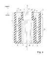
Fig. 4 is a cross-sectional view of a housing according to the embodiment. -
Fig. 5 is a side view and a cross-sectional view of a rotor according to the embodiment. - Hereinafter, with reference to the drawings, an embodiment according to the present invention will be explained. A rotary damper 1 according to the embodiment is interposed between a side wall of a carrier bag and a handle (a grip handle), and provides a braking torque (a rotational resistance force) relative to a rotation of the handle with respect to the side wall as well as rotatably supports the handle relative to the side wall. Hereinafter, for convenience of explanation, as shown in
Fig. 1 , a direction where an axis line A of the rotary damper 1 extends will be explained as an up-and-down direction. - As shown in
Fig. 1 to Fig. 3 , the rotary damper 1 includes ahousing 2 and arotor 3 as main structure elements. Thehousing 2 and therotor 3 may be resin molded articles, and are formed by injection molding of thermoplastic resin such as, for example, polyacetal (POM). - As shown in
Fig. 3 andFig. 4 , thehousing 2 includes a cylindricalouter cylinder 6 as an axis of the axis line A; a cylindricalinner cylinder 7 coaxially disposed inside theouter cylinder 6; and anannular bottom plate 8 disposed at lower ends of theouter cylinder 6 and theinner cylinder 7, and closing between lower edges of theouter cylinder 6 and theinner cylinder 7. Theouter cylinder 6 and theinner cylinder 7 concentrically disposed as an axis line of the axis line A, and thebottom plate 8 sealing one end of theouter cylinder 6 and theinner cylinder 7 define an annularliquid chamber 9 opening upward. On an inner peripheral side of theinner cylinder 7, both upper and lower ends are open. - The
inner cylinder 7 includes alarge diameter portion 12 and asmall diameter portion 13 coaxially disposed through astep portion 11, and having a cylindrical shape. Thelarge diameter portion 12 extends upward as the axis line of the axis line A from an inner peripheral edge of thebottom plate 8. Thestep portion 11 is formed in an annular flat plate extending on a surface orthogonal to the axis line A, and an outer peripheral edge is continuous to an upper end edge of thelarge diameter portion 12. Thesmall diameter portion 13 extends upward as the axis line of the axis line A from an inner peripheral edge of thestep portion 11. - As shown in
Fig. 2 to Fig. 4 , in thesmall diameter portion 13, there is formed a pair ofslits 14 extending downward from an upper end edge thereof. Theslits 14 are formed at symmetric positions around the axis line A, and extend up to an intermediate portion in the up-and-down direction of thesmall diameter portion 13. By forming the pair ofslits 14, anupper half portion 15 of thesmall diameter portion 13 is divided into two arc-like pieces, and can tilt slightly inward in a radial direction. On an outer peripheral surface (a first portion) 17 of theupper half portion 15 of thesmall diameter portion 13, there is formed alocking groove 16 extending in a circumferential direction. Thelocking groove 16 is continuous in the circumferential direction through the pair ofslits 14, and has an annular shape. - On an inner peripheral surface of the
large diameter portion 12, there is projected a plurality ofconvex pieces 18 extending in an axis line A direction. Theconvex pieces 18 are disposed at equal intervals in the circumferential direction, and projecting ends thereof project up to an inner peripheral surface of thesmall diameter portion 13 in the radial direction. On an outer peripheral surface of theouter cylinder 6, there is projected aconvex portion 19 extending in the axis line A direction. - As shown in
Fig. 3 andFig. 5 , therotor 3 includes acylindrical blade portion 21 as the axis line of the axis line A, and anannular flange 22 projecting outward in the radial direction from an upper end edge of theblade portion 21. Theblade portion 21 includes a cylindricalmain body portion 24 opening both ends and forming a large portion of theblade portion 21, and athick portion 25 continuous to an upper end of themain body portion 24 and having a thickness in a radial direction thicker than that of themain body portion 24. Themain body portion 24 and thethick portion 25 have an equal outer diameter, and an outer peripheral surface of theblade portion 21 forms one circumferential surface. An inner diameter of thethick portion 25 is formed smaller than an inner diameter of themain body portion 24, and at a boundary of inner peripheral surfaces of themain body portion 24 and thethick portion 25, there is formed astep portion 26 facing downward. Specifically, it can be said that themain body portion 24 enlarges a diameter of an inner peripheral portion relative to thethick portion 25, and enlarges an area of the inner peripheral surface. Theflange 22 may be omitted in other embodiments. - The
flange 22 extends along an upper end edge on an outer peripheral surface of thethick portion 25. On the outer peripheral surface of thethick portion 25 and in a vicinity of the upper end edge, there is formed an annular O-ring groove (an outside-seal-member receiving groove) 27 extending in the circumferential direction. It is preferable that the O-ring groove 27 is located closer to the upper end edge. Specifically, it is preferable that the outer peripheral surface of theblade portion 21 formed below the O-ring groove 27 becomes longer in the axis line A direction, and a surface area of the outer peripheral surface becomes larger. At a proper portion of themain body portion 24 of theblade portion 21, there is formed a throughhole 28 passing through theblade portion 21 in the radial direction (seeFig. 5 ). - At a boundary portion between the inner peripheral surface of the
thick portion 25 and thestep portion 26, there is formed an O-ring housing portion 31 expanded with a different level. The O-ring housing portion 31 expands a diameter around the axis line A, and a bottom face thereof forms a circumferential surface having a diameter same as that of the inner peripheral surface of themain body portion 24. On the inner peripheral surface of thethick portion 25, and in a portion (a second portion) 33 located above the O-ring housing portion 31, there is provided a lockingconvex portion 32 projecting inward in the radial direction and extending along the circumferential direction in an annular shape. Incidentally, the lockingconvex portion 32 may continuously extend in the circumferential direction. - On an upper end face of the
thick portion 25, there is formed a pair of bottomedfitting holes 34 at symmetric positions around the axis line A. Also, on the upper end face of thethick portion 25, there is formed a pair ofconnection pieces 35 projecting upward and extending in the radial direction at symmetric positions around the axis line A. - As shown in
Fig. 3 , in a state wherein theblade portion 21 is received in theliquid chamber 9, therotor 3 is disposed in thehousing 2. Themain body portion 24 of theblade portion 21 is disposed between thelarge diameter portion 12 and theouter cylinder 6, and thethick portion 25 is disposed between thesmall diameter portion 13 and theouter cylinder 6. The lockingconvex portion 32 of thethick portion 25 is locked in the lockinggroove 16 of thesmall diameter portion 13 rotatably around the axis line A so as to control a relative movement in the axis line A direction between therotor 3 and thehousing 2. A surface of theflange 22 facing downward faces an upper end face of theouter cylinder 6 through a gap. Incidentally, in the other embodiments, the surface of theflange 22 facing downward may slidingly contact with the upper end face of theouter cylinder 6. - In the O-
ring groove 27, there is disposed an outside O-ring (an outside seal member) 37, and in the O-ring housing portion 31, there is disposed an inside O-ring (an inside seal member) 38. The outside and inside O-rings ring 37 contacts with a bottom face of the O-ring groove 27 and a bottom face of theouter cylinder 6 so as to seal therebetween. The inside O-ring 38 contacts with an inner peripheral surface of the O-ring housing portion 31 and an outer peripheral surface of thesmall diameter portion 13 of theinner cylinder 7 so as to seal therebetween. Thehousing 2 and therotor 3 slidingly contact with the outside O-ring 37 and the inside O-ring 38 so as to relatively rotate mutually around the axis line A. In theliquid chamber 9 sealed by the outside O-ring 37 and the inside O-ring 38, there is filled a viscous fluid such as, for example, silicone oil, grease, and the like. - In the present embodiment, as shown in
Fig. 3 , in the axis line A direction, the outside O-ring 37 is disposed between the lockingconvex portion 32 and the inside O-ring 38. In the other embodiments, in the axis line A direction, positions of the outside O-ring 37 and the lockingconvex portion 32 may be located at the same position. It is preferable that the outside O-ring 37 and the inside O-ring 38 are disposed on a more upper end side in the axis line A direction. For example, the outside O-ring 37 may be disposed in such a way as to contact with an upper end edge of an inner peripheral surface of theouter cylinder 6. By disposing the outside and inside O-rings blade portion 21 and the viscous fluid can enlarge in the axis line A direction. - In the rotary damper 1 formed in the aforementioned manner, for example, the
housing 2 is connected to a support piece (not shown in the figures) connected to the side wall of the carrier bag, and therotor 3 is connected to the handle. In thehousing 2, an axis portion of the support piece is inserted into thelarge diameter portion 12 of theinner cylinder 7 from below and is caught on theconvex piece 18 around the axis line A, or the support piece receives theouter cylinder 6 and is caught on theconvex portion 19 around the axis line A, so that thehousing 2 is connected to the support piece relatively unrotatably around the axis line A. In therotor 3, thefitting hole 34 thereof and theconnection piece 35 are caught on the handle, so that therotor 3 is connected to the handle relatively unrotatably around the axis line A. Thereby, when the handle rotates relative to the side wall, therotor 3 rotates relative to thehousing 2, and by the viscous fluid enclosed inside theliquid chamber 9, a braking torque is generated relative to a rotation of therotor 3 relative to thehousing 2. - In the present embodiment, in a portion where the
blade portion 21 and theinner cylinder 7 face, and in an upper end in the axis line A direction, there are provided the lockinggroove 16 and the lockingconvex portion 32, so that while making the rotary damper 1 compact, the contact area between theblade portion 21 and the viscous fluid is maximized so as to increase the braking torque. In a portion where an inner peripheral surface of theblade portion 21 and an outer peripheral surface of theinner cylinder 7 face, or in a portion where an outer peripheral portion of theblade portion 21 and the inner peripheral surface of theouter cylinder 6 face, there are disposed the lockinggroove 16 and the lockingconvex portion 32, so that an effect on an external shape of the rotary damper 1 by the lockinggroove 16 and the lockingconvex portion 32 can be reduced. Consequently, the rotary damper 1 can be made compact. - The locking
groove 16 and the lockingconvex portion 32 are provided on theinner cylinder 7 and the inner peripheral surface of theblade portion 21 so as to enlarge a contact area between the outer peripheral surface of theblade portion 21 and the viscous fluid. The outer peripheral surface of theblade portion 21 is longer in the circumferential direction compared to the inner peripheral surface, so that providing the lockingconvex portion 32 on the inner peripheral surface rather than on the outer peripheral surface of theblade portion 21 reduces the sizes of the lockingconvex portion 32 and the lockinggroove 16 so as to increase the contact area between theblade portion 21 and the viscous fluid. Also, when therotor 3 rotates at a predetermined angle, the outer peripheral surface has a moving distance larger than that on the inner peripheral surface, so that a contact portion between the outer peripheral surface and the viscous fluid can generate a braking force per unit area larger than that in a contact portion between the inner peripheral surface and the viscous fluid. Consequently, the lockinggroove 16 or the lockingconvex portion 32 is provided on the inner peripheral surface of theblade portion 21, and a large contact range between the outer peripheral surface and the viscous fluid is ensured so as to enlarge the braking torque that the rotary damper 1 generates. Also, the lockinggroove 16 or the lockingconvex portion 32 is disposed at the upper end in the axis line A direction on the inner peripheral surface of theblade portion 21 so as to ensure a wide contact area between the inner peripheral surface of theblade portion 21 and the viscous fluid. - In the present embodiment, the inner peripheral portion of the
main body portion 24 of theblade portion 21 has the diameter in the radial direction larger than that of thethick portion 25 so as to enlarge a surface area of the inner peripheral surface. On the other hand, thethick portion 25 forms the O-ring groove 27 and the O-ring housing portion 31 so as to ensure a predetermined thickness. The inner diameter of themain body portion 24 becomes larger than the inner diameter of thethick portion 25, so that the area of the inner peripheral surface of themain body portion 24 increases, and a moving amount of the inner peripheral surface of themain body portion 24 per unit rotation angle of therotor 3 increases so as to increase the braking torque. In order to enlarge the inner peripheral surface of themain body portion 24, it is preferable that a length of thethick portion 25 in the axis line A direction is smaller. - A specific embodiment has been explained hereinabove; however, the present invention is not limited to the aforementioned embodiment, and can be widely modified. Connection methods between the
housing 2 and therotor 3, and a base to buffer the rotation and a rotation body are not limited to a structure shown in the present embodiment, and well-known various structures can be applied. - 1 ... a rotary damper, 2 ... a housing, 3 ... a rotor, 6 ... an outer cylinder, 7 ... an inner cylinder, 8 ... a bottom plate, 9 ... a liquid chamber, 12 ... a large diameter portion, 13 ... a small diameter portion, 16 ... a locking groove, 17 ... an outer peripheral surface (a first portion), 21 ... a blade portion, 24 ... a main body portion, 25 ... a thick portion, 27 ... an O-ring groove (an outside-seal-member receiving groove), 28 ... a through hole, 31 ... an O-ring housing portion, 32 ... a locking convex portion, 33 ... a portion (a second portion), 37 ... an outside O-ring (an outside seal member), 38 ... an inside O-ring (an inside seal member), A ... an axis line
Claims (2)
- A rotary damper, comprising:a housing including an outer cylinder having a predetermined axis line, an inner cylinder coaxially disposed inside the outer cylinder, and a bottom plate closing one end side in an axis line direction of the outer cylinder and the inner cylinder, wherein an annular liquid chamber is defined by the outer cylinder, the inner cylinder, and the bottom plate, and a viscous fluid is filled in the liquid chamber;a rotor including a cylindrical blade portion rotatably received in the liquid chamber coaxially with the outer cylinder;an annular locking groove extending in a circumferential direction in one of either a first portion which is an outer peripheral surface of the inner cylinder and is located at an end edge portion on a side opposed to a bottom plate side, or a second portion facing the first portion on an inner peripheral surface of the blade portion;a locking convex portion projecting from the other of either the first portion or the second portion, and locked in the locking groove so as to control a relative movement in the axis line direction between the housing and the rotor;an annular inside seal member interposed between a portion on the outer peripheral surface of the inner cylinder and on the bottom plate side more than the first portion, and the inner peripheral surface of the blade portion; andan annular outside seal member interposed between a vicinity of the other end in the axis line direction on an inner peripheral surface of the outer cylinder, and an outer peripheral surface of the blade portion.
- A rotary damper according to claim 1, wherein an annular outside-seal-member receiving groove extending in the circumferential direction to receive the outside seal member is formed at an end portion in the axis line direction on the outer peripheral surface of the blade portion.
Applications Claiming Priority (2)
| Application Number | Priority Date | Filing Date | Title |
|---|---|---|---|
| JP2012051274A JP5922446B2 (en) | 2012-03-08 | 2012-03-08 | Rotating damper |
| PCT/JP2013/001205 WO2013132793A1 (en) | 2012-03-08 | 2013-02-28 | Rotary damper |
Publications (3)
| Publication Number | Publication Date |
|---|---|
| EP2824356A1 true EP2824356A1 (en) | 2015-01-14 |
| EP2824356A4 EP2824356A4 (en) | 2015-12-02 |
| EP2824356B1 EP2824356B1 (en) | 2020-04-15 |
Family
ID=49116289
Family Applications (1)
| Application Number | Title | Priority Date | Filing Date |
|---|---|---|---|
| EP13757948.8A Active EP2824356B1 (en) | 2012-03-08 | 2013-02-28 | Rotary damper |
Country Status (6)
| Country | Link |
|---|---|
| US (1) | US9605725B2 (en) |
| EP (1) | EP2824356B1 (en) |
| JP (1) | JP5922446B2 (en) |
| CN (1) | CN104145131B (en) |
| ES (1) | ES2798802T3 (en) |
| WO (1) | WO2013132793A1 (en) |
Families Citing this family (6)
| Publication number | Priority date | Publication date | Assignee | Title |
|---|---|---|---|---|
| JP6262488B2 (en) * | 2013-10-10 | 2018-01-17 | 株式会社パイオラックス | Damper and handle device including the same |
| WO2017061147A1 (en) * | 2015-10-07 | 2017-04-13 | Tmtマシナリー株式会社 | Liquid damper system |
| US11686369B2 (en) | 2017-03-31 | 2023-06-27 | Tmt Machinery, Inc. | Vibration damping device and bobbin holder system |
| CN107878351A (en) * | 2017-11-07 | 2018-04-06 | 上汽通用汽车有限公司 | Upset label apparatus for automobile |
| IT201900023055A1 (en) * | 2019-12-05 | 2021-06-05 | Cultraro Automazione Eng S R L | Rotary damper with reduced dimensions |
| US12115117B2 (en) * | 2021-11-23 | 2024-10-15 | Stryker Corporation | Patient transport apparatus with throttle assembly damping |
Family Cites Families (14)
| Publication number | Priority date | Publication date | Assignee | Title |
|---|---|---|---|---|
| JP2539165Y2 (en) | 1990-06-11 | 1997-06-25 | 株式会社ニフコ | Rotary damper |
| WO2001010672A1 (en) * | 1999-08-05 | 2001-02-15 | Nifco Inc. | Oil cylindrical rotational damper |
| JP3781624B2 (en) * | 2000-02-18 | 2006-05-31 | 株式会社パイオラックス | Rotating damper |
| JP2002021902A (en) | 2000-07-05 | 2002-01-23 | Nifco Inc | Rotary damper and assist grip device |
| JP4524771B2 (en) * | 2001-01-26 | 2010-08-18 | 株式会社ニフコ | Rotating damper and assist grip device |
| JP4523737B2 (en) | 2001-04-27 | 2010-08-11 | 株式会社ニフコ | Damper device |
| JP4056906B2 (en) * | 2003-03-03 | 2008-03-05 | 株式会社パイオラックス | Heart cam-damper unit and opening / closing control device using the same |
| DE102004025276B4 (en) | 2004-05-19 | 2009-12-31 | Sulo Umwelttechnik Gmbh | damping element |
| JP4391397B2 (en) * | 2004-07-14 | 2009-12-24 | 株式会社ニフコ | Rotating damper |
| JP4553121B2 (en) * | 2004-11-30 | 2010-09-29 | 株式会社ニフコ | Rotating damper |
| JP2007102111A (en) | 2005-10-07 | 2007-04-19 | Victor Co Of Japan Ltd | Optical multilayer film and method for manufacturing optical multilayer film |
| ITTO20060179A1 (en) | 2006-03-09 | 2007-09-10 | Antonino Cultraro | DEVICE FOR BRAKING THE MOVEMENT OF A MOBILE ORGAN COMPARED TO A SUPPORT STRUCTURE |
| BRPI0722216A2 (en) * | 2007-12-31 | 2014-05-20 | Antonino Cultraro | ROTATING BUMPER HAVING THE IMPROVED BRAKING CHARACTERISTICS. |
| JP5330965B2 (en) * | 2009-11-18 | 2013-10-30 | 株式会社ニフコ | Rotating body braking structure |
-
2012
- 2012-03-08 JP JP2012051274A patent/JP5922446B2/en active Active
-
2013
- 2013-02-28 ES ES13757948T patent/ES2798802T3/en active Active
- 2013-02-28 CN CN201380012525.0A patent/CN104145131B/en active Active
- 2013-02-28 US US14/382,672 patent/US9605725B2/en active Active
- 2013-02-28 EP EP13757948.8A patent/EP2824356B1/en active Active
- 2013-02-28 WO PCT/JP2013/001205 patent/WO2013132793A1/en not_active Ceased
Also Published As
| Publication number | Publication date |
|---|---|
| CN104145131A (en) | 2014-11-12 |
| JP2013185649A (en) | 2013-09-19 |
| CN104145131B (en) | 2016-06-22 |
| WO2013132793A1 (en) | 2013-09-12 |
| EP2824356B1 (en) | 2020-04-15 |
| US20150034435A1 (en) | 2015-02-05 |
| ES2798802T3 (en) | 2020-12-14 |
| EP2824356A4 (en) | 2015-12-02 |
| JP5922446B2 (en) | 2016-05-24 |
| US9605725B2 (en) | 2017-03-28 |
Similar Documents
| Publication | Publication Date | Title |
|---|---|---|
| EP2824356B1 (en) | Rotary damper | |
| KR101878009B1 (en) | Rotary damper device and method for producing same | |
| US9103390B2 (en) | Rotary damper device with one-way clutch | |
| US9645606B2 (en) | Damping hinge structure and foldable electronic device | |
| US10844925B2 (en) | Rotary damper | |
| US9182003B2 (en) | Damper device | |
| EP3828448B1 (en) | Sealing device | |
| EP3828447B1 (en) | Sealing device | |
| WO2017217432A1 (en) | Damper | |
| CN108852131B (en) | Fluid damping device and equipment with damping | |
| KR200275886Y1 (en) | Friction hinge device | |
| JP4018656B2 (en) | Door check device | |
| CN102549295B (en) | rotary damper | |
| CN112294169B (en) | Fluid damping device | |
| CN107939820A (en) | The closed shaft and electronic equipment of torsional force linear change | |
| WO2013031515A1 (en) | Rotary damper | |
| JP6577862B2 (en) | Rotary damper | |
| KR20030035857A (en) | Rotary damper | |
| JP2009102859A (en) | Door checking device | |
| JP6487707B2 (en) | Fluid damper device and damper equipped device |
Legal Events
| Date | Code | Title | Description |
|---|---|---|---|
| PUAI | Public reference made under article 153(3) epc to a published international application that has entered the european phase |
Free format text: ORIGINAL CODE: 0009012 |
|
| 17P | Request for examination filed |
Effective date: 20140905 |
|
| AK | Designated contracting states |
Kind code of ref document: A1 Designated state(s): AL AT BE BG CH CY CZ DE DK EE ES FI FR GB GR HR HU IE IS IT LI LT LU LV MC MK MT NL NO PL PT RO RS SE SI SK SM TR |
|
| AX | Request for extension of the european patent |
Extension state: BA ME |
|
| RIN1 | Information on inventor provided before grant (corrected) |
Inventor name: SETO, MASATORA Inventor name: LEE, YOUNG KOOK |
|
| DAX | Request for extension of the european patent (deleted) | ||
| RA4 | Supplementary search report drawn up and despatched (corrected) |
Effective date: 20151030 |
|
| RIC1 | Information provided on ipc code assigned before grant |
Ipc: F16F 9/12 20060101AFI20151026BHEP |
|
| STAA | Information on the status of an ep patent application or granted ep patent |
Free format text: STATUS: EXAMINATION IS IN PROGRESS |
|
| 17Q | First examination report despatched |
Effective date: 20180925 |
|
| GRAP | Despatch of communication of intention to grant a patent |
Free format text: ORIGINAL CODE: EPIDOSNIGR1 |
|
| STAA | Information on the status of an ep patent application or granted ep patent |
Free format text: STATUS: GRANT OF PATENT IS INTENDED |
|
| INTG | Intention to grant announced |
Effective date: 20200113 |
|
| GRAS | Grant fee paid |
Free format text: ORIGINAL CODE: EPIDOSNIGR3 |
|
| GRAA | (expected) grant |
Free format text: ORIGINAL CODE: 0009210 |
|
| STAA | Information on the status of an ep patent application or granted ep patent |
Free format text: STATUS: THE PATENT HAS BEEN GRANTED |
|
| RAP1 | Party data changed (applicant data changed or rights of an application transferred) |
Owner name: NIFCO INC. |
|
| RIN1 | Information on inventor provided before grant (corrected) |
Inventor name: SETO, MASATORA Inventor name: LEE, YOUNG KOOK |
|
| AK | Designated contracting states |
Kind code of ref document: B1 Designated state(s): AL AT BE BG CH CY CZ DE DK EE ES FI FR GB GR HR HU IE IS IT LI LT LU LV MC MK MT NL NO PL PT RO RS SE SI SK SM TR |
|
| REG | Reference to a national code |
Ref country code: CH Ref legal event code: EP |
|
| REG | Reference to a national code |
Ref country code: DE Ref legal event code: R096 Ref document number: 602013067945 Country of ref document: DE |
|
| REG | Reference to a national code |
Ref country code: IE Ref legal event code: FG4D |
|
| REG | Reference to a national code |
Ref country code: AT Ref legal event code: REF Ref document number: 1257666 Country of ref document: AT Kind code of ref document: T Effective date: 20200515 |
|
| REG | Reference to a national code |
Ref country code: NL Ref legal event code: MP Effective date: 20200415 |
|
| REG | Reference to a national code |
Ref country code: LT Ref legal event code: MG4D |
|
| PG25 | Lapsed in a contracting state [announced via postgrant information from national office to epo] |
Ref country code: PT Free format text: LAPSE BECAUSE OF FAILURE TO SUBMIT A TRANSLATION OF THE DESCRIPTION OR TO PAY THE FEE WITHIN THE PRESCRIBED TIME-LIMIT Effective date: 20200817 Ref country code: NL Free format text: LAPSE BECAUSE OF FAILURE TO SUBMIT A TRANSLATION OF THE DESCRIPTION OR TO PAY THE FEE WITHIN THE PRESCRIBED TIME-LIMIT Effective date: 20200415 Ref country code: SE Free format text: LAPSE BECAUSE OF FAILURE TO SUBMIT A TRANSLATION OF THE DESCRIPTION OR TO PAY THE FEE WITHIN THE PRESCRIBED TIME-LIMIT Effective date: 20200415 Ref country code: IS Free format text: LAPSE BECAUSE OF FAILURE TO SUBMIT A TRANSLATION OF THE DESCRIPTION OR TO PAY THE FEE WITHIN THE PRESCRIBED TIME-LIMIT Effective date: 20200815 Ref country code: LT Free format text: LAPSE BECAUSE OF FAILURE TO SUBMIT A TRANSLATION OF THE DESCRIPTION OR TO PAY THE FEE WITHIN THE PRESCRIBED TIME-LIMIT Effective date: 20200415 Ref country code: NO Free format text: LAPSE BECAUSE OF FAILURE TO SUBMIT A TRANSLATION OF THE DESCRIPTION OR TO PAY THE FEE WITHIN THE PRESCRIBED TIME-LIMIT Effective date: 20200715 Ref country code: FI Free format text: LAPSE BECAUSE OF FAILURE TO SUBMIT A TRANSLATION OF THE DESCRIPTION OR TO PAY THE FEE WITHIN THE PRESCRIBED TIME-LIMIT Effective date: 20200415 Ref country code: GR Free format text: LAPSE BECAUSE OF FAILURE TO SUBMIT A TRANSLATION OF THE DESCRIPTION OR TO PAY THE FEE WITHIN THE PRESCRIBED TIME-LIMIT Effective date: 20200716 |
|
| REG | Reference to a national code |
Ref country code: AT Ref legal event code: MK05 Ref document number: 1257666 Country of ref document: AT Kind code of ref document: T Effective date: 20200415 |
|
| PG25 | Lapsed in a contracting state [announced via postgrant information from national office to epo] |
Ref country code: HR Free format text: LAPSE BECAUSE OF FAILURE TO SUBMIT A TRANSLATION OF THE DESCRIPTION OR TO PAY THE FEE WITHIN THE PRESCRIBED TIME-LIMIT Effective date: 20200415 Ref country code: LV Free format text: LAPSE BECAUSE OF FAILURE TO SUBMIT A TRANSLATION OF THE DESCRIPTION OR TO PAY THE FEE WITHIN THE PRESCRIBED TIME-LIMIT Effective date: 20200415 Ref country code: RS Free format text: LAPSE BECAUSE OF FAILURE TO SUBMIT A TRANSLATION OF THE DESCRIPTION OR TO PAY THE FEE WITHIN THE PRESCRIBED TIME-LIMIT Effective date: 20200415 Ref country code: BG Free format text: LAPSE BECAUSE OF FAILURE TO SUBMIT A TRANSLATION OF THE DESCRIPTION OR TO PAY THE FEE WITHIN THE PRESCRIBED TIME-LIMIT Effective date: 20200715 |
|
| REG | Reference to a national code |
Ref country code: ES Ref legal event code: FG2A Ref document number: 2798802 Country of ref document: ES Kind code of ref document: T3 Effective date: 20201214 |
|
| PG25 | Lapsed in a contracting state [announced via postgrant information from national office to epo] |
Ref country code: AL Free format text: LAPSE BECAUSE OF FAILURE TO SUBMIT A TRANSLATION OF THE DESCRIPTION OR TO PAY THE FEE WITHIN THE PRESCRIBED TIME-LIMIT Effective date: 20200415 |
|
| REG | Reference to a national code |
Ref country code: DE Ref legal event code: R097 Ref document number: 602013067945 Country of ref document: DE |
|
| PG25 | Lapsed in a contracting state [announced via postgrant information from national office to epo] |
Ref country code: RO Free format text: LAPSE BECAUSE OF FAILURE TO SUBMIT A TRANSLATION OF THE DESCRIPTION OR TO PAY THE FEE WITHIN THE PRESCRIBED TIME-LIMIT Effective date: 20200415 Ref country code: EE Free format text: LAPSE BECAUSE OF FAILURE TO SUBMIT A TRANSLATION OF THE DESCRIPTION OR TO PAY THE FEE WITHIN THE PRESCRIBED TIME-LIMIT Effective date: 20200415 Ref country code: AT Free format text: LAPSE BECAUSE OF FAILURE TO SUBMIT A TRANSLATION OF THE DESCRIPTION OR TO PAY THE FEE WITHIN THE PRESCRIBED TIME-LIMIT Effective date: 20200415 Ref country code: CZ Free format text: LAPSE BECAUSE OF FAILURE TO SUBMIT A TRANSLATION OF THE DESCRIPTION OR TO PAY THE FEE WITHIN THE PRESCRIBED TIME-LIMIT Effective date: 20200415 Ref country code: IT Free format text: LAPSE BECAUSE OF FAILURE TO SUBMIT A TRANSLATION OF THE DESCRIPTION OR TO PAY THE FEE WITHIN THE PRESCRIBED TIME-LIMIT Effective date: 20200415 Ref country code: SM Free format text: LAPSE BECAUSE OF FAILURE TO SUBMIT A TRANSLATION OF THE DESCRIPTION OR TO PAY THE FEE WITHIN THE PRESCRIBED TIME-LIMIT Effective date: 20200415 Ref country code: DK Free format text: LAPSE BECAUSE OF FAILURE TO SUBMIT A TRANSLATION OF THE DESCRIPTION OR TO PAY THE FEE WITHIN THE PRESCRIBED TIME-LIMIT Effective date: 20200415 |
|
| PLBE | No opposition filed within time limit |
Free format text: ORIGINAL CODE: 0009261 |
|
| STAA | Information on the status of an ep patent application or granted ep patent |
Free format text: STATUS: NO OPPOSITION FILED WITHIN TIME LIMIT |
|
| PG25 | Lapsed in a contracting state [announced via postgrant information from national office to epo] |
Ref country code: SK Free format text: LAPSE BECAUSE OF FAILURE TO SUBMIT A TRANSLATION OF THE DESCRIPTION OR TO PAY THE FEE WITHIN THE PRESCRIBED TIME-LIMIT Effective date: 20200415 Ref country code: PL Free format text: LAPSE BECAUSE OF FAILURE TO SUBMIT A TRANSLATION OF THE DESCRIPTION OR TO PAY THE FEE WITHIN THE PRESCRIBED TIME-LIMIT Effective date: 20200415 |
|
| 26N | No opposition filed |
Effective date: 20210118 |
|
| PG25 | Lapsed in a contracting state [announced via postgrant information from national office to epo] |
Ref country code: SI Free format text: LAPSE BECAUSE OF FAILURE TO SUBMIT A TRANSLATION OF THE DESCRIPTION OR TO PAY THE FEE WITHIN THE PRESCRIBED TIME-LIMIT Effective date: 20200415 |
|
| PG25 | Lapsed in a contracting state [announced via postgrant information from national office to epo] |
Ref country code: MC Free format text: LAPSE BECAUSE OF FAILURE TO SUBMIT A TRANSLATION OF THE DESCRIPTION OR TO PAY THE FEE WITHIN THE PRESCRIBED TIME-LIMIT Effective date: 20200415 |
|
| GBPC | Gb: european patent ceased through non-payment of renewal fee |
Effective date: 20210228 |
|
| REG | Reference to a national code |
Ref country code: BE Ref legal event code: MM Effective date: 20210228 |
|
| PG25 | Lapsed in a contracting state [announced via postgrant information from national office to epo] |
Ref country code: LI Free format text: LAPSE BECAUSE OF NON-PAYMENT OF DUE FEES Effective date: 20210228 Ref country code: LU Free format text: LAPSE BECAUSE OF NON-PAYMENT OF DUE FEES Effective date: 20210228 Ref country code: CH Free format text: LAPSE BECAUSE OF NON-PAYMENT OF DUE FEES Effective date: 20210228 |
|
| PG25 | Lapsed in a contracting state [announced via postgrant information from national office to epo] |
Ref country code: GB Free format text: LAPSE BECAUSE OF NON-PAYMENT OF DUE FEES Effective date: 20210228 Ref country code: IE Free format text: LAPSE BECAUSE OF NON-PAYMENT OF DUE FEES Effective date: 20210228 |
|
| PGFP | Annual fee paid to national office [announced via postgrant information from national office to epo] |
Ref country code: FR Payment date: 20220118 Year of fee payment: 10 Ref country code: ES Payment date: 20220301 Year of fee payment: 10 |
|
| PG25 | Lapsed in a contracting state [announced via postgrant information from national office to epo] |
Ref country code: BE Free format text: LAPSE BECAUSE OF NON-PAYMENT OF DUE FEES Effective date: 20210228 |
|
| PG25 | Lapsed in a contracting state [announced via postgrant information from national office to epo] |
Ref country code: HU Free format text: LAPSE BECAUSE OF FAILURE TO SUBMIT A TRANSLATION OF THE DESCRIPTION OR TO PAY THE FEE WITHIN THE PRESCRIBED TIME-LIMIT; INVALID AB INITIO Effective date: 20130228 |
|
| PG25 | Lapsed in a contracting state [announced via postgrant information from national office to epo] |
Ref country code: CY Free format text: LAPSE BECAUSE OF FAILURE TO SUBMIT A TRANSLATION OF THE DESCRIPTION OR TO PAY THE FEE WITHIN THE PRESCRIBED TIME-LIMIT Effective date: 20200415 |
|
| PG25 | Lapsed in a contracting state [announced via postgrant information from national office to epo] |
Ref country code: FR Free format text: LAPSE BECAUSE OF NON-PAYMENT OF DUE FEES Effective date: 20230228 |
|
| REG | Reference to a national code |
Ref country code: ES Ref legal event code: FD2A Effective date: 20240429 |
|
| PG25 | Lapsed in a contracting state [announced via postgrant information from national office to epo] |
Ref country code: MK Free format text: LAPSE BECAUSE OF FAILURE TO SUBMIT A TRANSLATION OF THE DESCRIPTION OR TO PAY THE FEE WITHIN THE PRESCRIBED TIME-LIMIT Effective date: 20200415 |
|
| PG25 | Lapsed in a contracting state [announced via postgrant information from national office to epo] |
Ref country code: ES Free format text: LAPSE BECAUSE OF NON-PAYMENT OF DUE FEES Effective date: 20230301 |
|
| PG25 | Lapsed in a contracting state [announced via postgrant information from national office to epo] |
Ref country code: ES Free format text: LAPSE BECAUSE OF NON-PAYMENT OF DUE FEES Effective date: 20230301 |
|
| PG25 | Lapsed in a contracting state [announced via postgrant information from national office to epo] |
Ref country code: MT Free format text: LAPSE BECAUSE OF FAILURE TO SUBMIT A TRANSLATION OF THE DESCRIPTION OR TO PAY THE FEE WITHIN THE PRESCRIBED TIME-LIMIT Effective date: 20200415 |
|
| PG25 | Lapsed in a contracting state [announced via postgrant information from national office to epo] |
Ref country code: TR Free format text: LAPSE BECAUSE OF FAILURE TO SUBMIT A TRANSLATION OF THE DESCRIPTION OR TO PAY THE FEE WITHIN THE PRESCRIBED TIME-LIMIT Effective date: 20200415 |
|
| PGFP | Annual fee paid to national office [announced via postgrant information from national office to epo] |
Ref country code: DE Payment date: 20260102 Year of fee payment: 14 |