EP2824021A1 - Attachment structure for portable information terminal in saddle-type vehicle - Google Patents
Attachment structure for portable information terminal in saddle-type vehicle Download PDFInfo
- Publication number
- EP2824021A1 EP2824021A1 EP13758389.4A EP13758389A EP2824021A1 EP 2824021 A1 EP2824021 A1 EP 2824021A1 EP 13758389 A EP13758389 A EP 13758389A EP 2824021 A1 EP2824021 A1 EP 2824021A1
- Authority
- EP
- European Patent Office
- Prior art keywords
- personal digital
- digital assistant
- holder
- vehicle
- terminal
- Prior art date
- Legal status (The legal status is an assumption and is not a legal conclusion. Google has not performed a legal analysis and makes no representation as to the accuracy of the status listed.)
- Granted
Links
Images




Classifications
-
- B—PERFORMING OPERATIONS; TRANSPORTING
- B62—LAND VEHICLES FOR TRAVELLING OTHERWISE THAN ON RAILS
- B62J—CYCLE SADDLES OR SEATS; AUXILIARY DEVICES OR ACCESSORIES SPECIALLY ADAPTED TO CYCLES AND NOT OTHERWISE PROVIDED FOR, e.g. ARTICLE CARRIERS OR CYCLE PROTECTORS
- B62J11/00—Supporting arrangements specially adapted for fastening specific devices to cycles, e.g. supports for attaching maps
-
- B—PERFORMING OPERATIONS; TRANSPORTING
- B62—LAND VEHICLES FOR TRAVELLING OTHERWISE THAN ON RAILS
- B62J—CYCLE SADDLES OR SEATS; AUXILIARY DEVICES OR ACCESSORIES SPECIALLY ADAPTED TO CYCLES AND NOT OTHERWISE PROVIDED FOR, e.g. ARTICLE CARRIERS OR CYCLE PROTECTORS
- B62J50/00—Arrangements specially adapted for use on cycles not provided for in main groups B62J1/00 - B62J45/00
- B62J50/20—Information-providing devices
- B62J50/21—Information-providing devices intended to provide information to rider or passenger
- B62J50/22—Information-providing devices intended to provide information to rider or passenger electronic, e.g. displays
-
- B—PERFORMING OPERATIONS; TRANSPORTING
- B62—LAND VEHICLES FOR TRAVELLING OTHERWISE THAN ON RAILS
- B62J—CYCLE SADDLES OR SEATS; AUXILIARY DEVICES OR ACCESSORIES SPECIALLY ADAPTED TO CYCLES AND NOT OTHERWISE PROVIDED FOR, e.g. ARTICLE CARRIERS OR CYCLE PROTECTORS
- B62J50/00—Arrangements specially adapted for use on cycles not provided for in main groups B62J1/00 - B62J45/00
- B62J50/20—Information-providing devices
- B62J50/21—Information-providing devices intended to provide information to rider or passenger
- B62J50/225—Mounting arrangements therefor
-
- B—PERFORMING OPERATIONS; TRANSPORTING
- B62—LAND VEHICLES FOR TRAVELLING OTHERWISE THAN ON RAILS
- B62K—CYCLES; CYCLE FRAMES; CYCLE STEERING DEVICES; RIDER-OPERATED TERMINAL CONTROLS SPECIALLY ADAPTED FOR CYCLES; CYCLE AXLE SUSPENSIONS; CYCLE SIDECARS, FORECARS, OR THE LIKE
- B62K19/00—Cycle frames
- B62K19/30—Frame parts shaped to receive other cycle parts or accessories
- B62K19/40—Frame parts shaped to receive other cycle parts or accessories for attaching accessories, e.g. article carriers, lamps
-
- B—PERFORMING OPERATIONS; TRANSPORTING
- B62—LAND VEHICLES FOR TRAVELLING OTHERWISE THAN ON RAILS
- B62K—CYCLES; CYCLE FRAMES; CYCLE STEERING DEVICES; RIDER-OPERATED TERMINAL CONTROLS SPECIALLY ADAPTED FOR CYCLES; CYCLE AXLE SUSPENSIONS; CYCLE SIDECARS, FORECARS, OR THE LIKE
- B62K2202/00—Motorised scooters
Definitions
- the present invention relates to a personal digital assistant attachment structure for a saddle-ride vehicle such as a motorcycle.
- Patent Document 1 discloses that, in a motorcycle to which a personal digital assistant such as a portable telephone is removably attached, a structure in which a recess-shaped terminal holder is provided which holds the personal digital assistant in an upright state in front of a meter unit provided at the center of the bar handle.
- Patent Document 1 Japanese Unexamined Patent Application, First Publication No. 2003-137161
- the recess-shaped terminal holder is provided in front of the meter unit.
- the invention provides the personal digital assistant attachment structure for a saddle-ride vehicle, in which a personal digital assistant can be attached to a terminal holder provided on the vehicle body regardless of the size or the type of the personal digital assistant, and communicating and charging of the personal digital assistant can be carried out.
- a personal digital assistant attachment structure which serves as a means to solve the above-mentioned problem and is used for a saddle-ride vehicle, is a personal digital assistant attachment structure for a saddle-ride vehicle, removably attaching a personal digital assistant including a display screen to a vehicle body.
- the attachment structure includes: a terminal holder that includes a connector cord and a supported portion, is provided separately from the vehicle body, and holds the personal digital assistant, the connector cord including a first end and a second end different from the first end, the first end being connected to the personal digital assistant so that the first end is capable of supplying at least one of electric power and data to the personal digital assistant from the vehicle body, the supported portion including a cord holder and a holder terminal, the cord holder holding the connector cord, the holder terminal being connected to the second end of the connector cord; and a holder support that is provided integrally with the vehicle body, is removably engaged with the supported portion and to support the terminal holder, and includes a vehicle-body-side terminal, the vehicle-body-side terminal being removably connected to the holder terminal during engagement of the supported portion.
- the saddle-ride vehicle means general vehicles on which a driver straddles and is seated, such as a motorcycle (including a motorized bicycle and a scooter-type vehicle), a three wheeled vehicle (including a vehicle provided with front-two wheels and rear-single wheel in addition to a vehicle provided with a front-single wheel and rear-two wheels), or a four-wheeled vehicle.
- a motorcycle including a motorized bicycle and a scooter-type vehicle
- a three wheeled vehicle including a vehicle provided with front-two wheels and rear-single wheel in addition to a vehicle provided with a front-single wheel and rear-two wheels
- a four-wheeled vehicle such as a motorcycle (including a motorized bicycle and a scooter-type vehicle), a three wheeled vehicle (including a vehicle provided with front-two wheels and rear-single wheel in addition to a vehicle provided with a front-single wheel and rear-two wheels), or a four-wheeled vehicle.
- It may have a lock mechanism that is provided between the holder support and the supported portion, and limits the supported portion engaged with the holder support from being removed from the holder support.
- a plurality of supported portions are provided at the holder support, the cord holder is provided in at least one of the supported portions, and the lock mechanism is provided between the holder support and at least one of the supported portions at which the cord holder is not provided.
- the supported portion is formed in a rod shape, is inserted into the holder support in the longitudinal direction of the supported portion, and includes a narrow portion provided on an intermediate portion of the supported portion in the longitudinal direction
- the holder support includes a fork advance-retreat mechanism that causes a fork member to move forward and backward in a direction orthogonal to the longitudinal direction and thereby causes the fork member to engage with and disengage from the narrow portion
- the lock mechanism is constituted of the narrow portion and the fork advance-retreat mechanism.
- the supported portion is formed in a plate shape, is inserted into the holder support in a direction along a top surface and a back surface of the supported portion, and has a hole portion formed at a predetermined position on the top surface and the back surface
- the holder support includes a pin advance-retreat mechanism that is used to cause a pin to move forward and backward in a direction orthogonal to the top surface and the back surface, and attach the pin to the hole portion and remove the pin from the hole portion
- the lock mechanism is constituted of the hole portion and the pin advance-retreat mechanism.
- the personal digital assistant attachment structure for a saddle-ride vehicle may further include a vehicle-body-side fixation member provided at an attachment position of the personal digital assistant, wherein the terminal holder further includes: a case capable of accommodating the personal digital assistant; a spacer that is selected so as to correspond to the personal digital assistant and is accommodated in the case; a cover that covers an opening of the case; and a hinge that pivotally supports the cover so to be openable and closable with respect to the case, the supported portion is formed integrally with the terminal holder, and the cover has: a window that exposes a display screen of the personal digital assistant to outside of a holder; and an engagement portion that is to be engaged with the vehicle-body-side fixation member in a state where the case is closed during attachment of the terminal holder to the vehicle body and thereby limits an operation of opening the cover.
- the terminal holder further includes: a case capable of accommodating the personal digital assistant; a spacer that is selected so as to correspond to the personal digital assistant and is accommodated in the case;
- the personal digital assistant attachment structure for a saddle-ride vehicle may further include a vehicle-body-side fixation member provided at an attachment position of the personal digital assistant, wherein the terminal holder further includes: a case capable of accommodating the personal digital assistant; a spacer that is selected so as to match to the personal digital assistant and is accommodated in the case; a cover that covers an opening of the case; and a hinge that pivotally supports the cover so to be openable and closable with respect to the case, the supported portion is formed integrally with the terminal holder, and an engagement portion that is to be engaged with the cover in a state where the case is closed during attachment of the terminal holder and thereby limits an operation of opening the cover is provided on the vehicle-body-side fixation member.
- the terminal holder includes a seal that is provided along an inner circumferential edge of a window of the cover so as to come into tight contact with the periphery of a display screen of the personal digital assistant inside the case when the cover is closed.
- a light receiver that is used to capture an image of a front of the vehicle is provided on a front surface of the personal digital assistant during attachment thereof to the vehicle body, and an exposed hole that allows the light receiver to be exposed to the front of the vehicle is provided on the terminal holder.
- the aspect of the invention as a result of holding the personal digital assistant on the terminal holder that is separated from a vehicle body, attaching the terminal holder to the vehicle, and only causing the terminal holder to correspond to personal digital assistants which are different in the size or the type thereof, it is possible to attach the personal digital assistant to the vehicle.
- the supported portion of the terminal holder and the holder support of the vehicle as a connector and connecting the personal digital assistant to a battery or a controller of the vehicle, it is possible to charge the personal digital assistant and it is possible to display a variety of vehicle information.
- the personal digital assistant it is possible to prevent the personal digital assistant from unintentionally dropping off and from being stolen in a state of being attached to the vehicle body.
- a cord-wiring path is easily ensured in one of the supported portions, and the lock mechanism can be configured by effectively utilizing a space around the supported portion other than the supported portion in which the cord-wiring path is ensured.
- a lock mechanism having a simplified configuration can be provided.
- the display screen of personal digital assistant is visible from the outside of the holder, and it is possible to easily configure a constitution that limits an operation of opening the cover.
- the operation of the personal digital assistant and the vehicle can be controlled based on image information of the front of the vehicle which is obtained by the light receiver.
- the arrow FR indicating the front direction of the vehicle
- the arrow LH indicating the left direction of the vehicle
- the arrow UP indicating the upper direction of the vehicle are suitably shown in the drawings used for explanation described below.
- a motorcycle 1 shown in FIG. 1 is a scooter-type vehicle having a low floor 2, rotationally drives a rear wheel 5 that is pivotally supported by a wheel shaft 5a provided at a rear end of a rear swing arm 3 due to rotational power of an electric motor 4 built in the rear swing arm 3, and thereby runs.
- a battery case 6 is provided under the low floor 2, and the battery case accommodates a high voltage battery (not shown in the figure) of 48 to 72V in voltage and serves as a power supply for the electric motor 4, and BMU (Battery Managing Unit, not shown in the figure) that controls discharging and charging of the high voltage battery.
- a high voltage battery not shown in the figure
- BMU Battery Managing Unit
- a vehicle body frame 7 of the motorcycle 1 includes a head pipe 8 that is on the front end portion thereof and is backward inclined with respect to the vertical direction.
- a steering stem 9 is rotatably supported by the head pipe 8.
- the steering stem 9 includes a stem pipe (not shown in the figure) that is inserted into the head pipe 8 from the lower side thereof.
- a steering bar handle 13 is rotatably and integrally attached to the stem pipe via a handle stem 14 at the protruding portion that upwardly protrudes from the head pipe 8 at the stem pipe.
- a seat 15 on which an occupant is to be seated is provided rearward of the bar handle 13 with a straddle space M interposed therebetween.
- the rear swing arm 3 has a front end portion that is supported by a pivot portion located at a lower portion of a vehicle body so as to be capable of swinging in the vertical direction.
- a cantilever type such that the rear wheel 5 is pivotally supported by only an arm provided at the left side in the vehicle width direction is adopted.
- the rear end of the left arm of the rear swing arm 3 is supported by the left-side rear end of the vehicle body frame 7 with a rear cushion 16 interposed therebetween.
- the electric motor 4 a centrifugal clutch (not shown in the figure) serving as a cut mechanism of rotating drive force, a reduction gear mechanism, and a PDU 17 (Power Drive Unit) that controls the output of the electric motor 4 are concentratedly arranged.
- An ECU 18 (electronic control unit) is provided integrally with the PDU 17.
- the vehicle body frame 7 of the motorcycle 1 is covered with a vehicle body cover 21 made of a synthetic resin material.
- the vehicle body cover 21 includes: a front cover 22 that covers the front of the peripheral portion of the head pipe 8; a leg shield 23 that covers the rear of the peripheral portion of the head pipe 8; the low floor 2 on which the feet of the occupant seated on the seat 15 are mounted, which extends from the lower portion of the leg shield 23 to the rear, and which covers the battery case 6 from above; a pair of right and left floor side covers 24 that droop from the external side of the low floor 2; an under cover 25 that connects the lower edges of the paired right and left floor side covers 24; so as to cover the front of a lower space of the seat 15; a seat-front-lower-portion cover 26 that is provided upright from the rear end of the low floor 2; a pair of right and left side covers 27 that extend to the rear of the outside portion of the seat-front-lower-portion cover 26 so as to cover the side portions of the lower space of the seat 15; and a rear cover 28 that extends to the rear of the right and left side covers 27 so as to cover the
- a lid 29 that opens or closes a charging port of a high voltage battery provided inside the battery case 6 is provided on the left side cover 27.
- An article storage box 31 which is openable and closable by the seat 15 is disposed in the lower space of the seat 15.
- a low voltage battery 32 of 12V is disposed at a bottom portion the article storage box 31.
- a seat sensor 33 that detects the occupant seated thereon is placed at a position close to the top surface of the seat 15 (seating surface).
- a sound emitter 34 is disposed inside the front cover 22, and the sound emitter alerts someone that the own vehicle approaches the periphery thereof at extremely low speed.
- a main key switch 35 including a key cylinder is disposed at the right side of the leg shield 23.
- left and right handle grips 13a are provided at both right and left sides of the bar handle 13.
- the center portion of the bar handle 13 is curved in a U-shape so as to protrude downward in a front view.
- the bar handle 13 is covered with a steering handlebar cover 36 that constitutes part of the vehicle body cover 21.
- the line CL in the drawings indicates the center line that defines the right and left of the vehicle body.
- the steering handlebar cover 36 is divisionally configured by: a steering-handlebar front cover 36a that covers the front of the bar handle 13; and a steering-handlebar rear cover 36b that covers the rear of the bar handle 13.
- the line K in the drawings indicates the boundary line between the upper surface of the steering-handlebar front cover 36a and the upper surface of the steering-handlebar rear cover 36b.
- a meter unit 37 including a speedometer or the like is provided on the center portion between the right and left of the steering-handlebar rear cover 36b.
- Exposed holes 38 are provided on both the upper-right and upper-left sides of the steering-handlebar front cover 36a, the exposed holes allow mirror-fastening bosses 41 b to be exposed to the outside of the cover, and the bosses are provided inside the steering handlebar cover 36.
- the steering handlebar cover 36 is fixedly attached to the vehicle body, and a tool is necessary for attachment and replacement of the steering handlebar cover 36.
- lever holders 41 that support brake levers 41a are attached to the positions close to the base ends of the respective left and right handle grips 13a.
- the mirror-fastening bosses 41b that tighten mirror stays 39a provided at the right and left rearview mirrors 39 are provided on the respective right and left lever holders 41 by integral molding or the like.
- Operation switches 42 of a lamp unit or the like are provided on both the upper-right and upper-left sides of the steering-handlebar rear cover 36b.
- the center portion is between the right and left of the steering-handlebar rear cover 36b, the meter unit 37 or the like are provided on the center portion, the switches 42 or the like are provided on both the right and left sides portions, and trailing edge configurations between the center portion and both the right and left sides portions is curved portions 43 having a projected shape that protrudes forward in a top view.
- a holder support 47 that supports a terminal holder 51 is provided in the steering-handlebar front cover 36a, and the terminal holder holds (accommodates) a personal digital assistant 45 therein.
- the personal digital assistant 45 for example, a smartphone (a multifunction portable telephone provided with a PDA function) is adopted.
- the personal digital assistant 45 includes a relatively large-scaled display screen 45a serving as a touch panel.
- the personal digital assistant 45 can display an internet screen and a navigation screen using a GPS on the display screen 45a.
- the holder support 47 is fixed integrally to the bar handle 13 by, for example, tightening or the like.
- the holder support 47 includes a pair of right and left leg supports 47a that hold a pair of right and left supporting legs 56 of the terminal holder 51 in a state where the paired right and left supporting legs 56 are inserted into the holder support.
- a pair of right and left foot insertion holes 47b are formed on each of the upper-right side and upper-left side of the steering-handlebar front cover 36a.
- the right and left supporting legs 56 of the terminal holder 51 are inserted through the foot insertion holes 47b and are fixed to the right and left leg supports 47a of the holder support 47 which are provided inside the steering-handlebar front cover 36a.
- a manual type shutter 47c capable of watertightly sealing the right and left foot insertion holes 47b is individually provided on each of the right and left foot insertion holes 47b.
- the terminal holder 51 is formed in a case shape which is separated from the vehicle body of the motorcycle 1, accommodates and holds the personal digital assistant 45 thereinside, and can removably attach the personal digital assistant 45 to the vehicle body.
- the terminal holder 51 is formed in a rectangular thick plate shape slightly larger than the personal digital assistant 45 so as to be able to accommodate the personal digital assistant 45 that is formed in a rectangular thick plate shape.
- the personal digital assistant 45 and the terminal holder 51 are arranged in the position where the long side of the rectangle is parallel to the horizontal direction of the motorcycle 1 and both surfaces in the thickness direction of the personal digital assistant 45 and the terminal holder 51 are tilted slightly forward with respect to the vertical direction in a state of being directed to the front-back direction of the motorcycle 1 during attachment thereof to the vehicle body.
- the display screen 45a of the personal digital assistant 45 is located to face the rear side (occupant side).
- the terminal holder 51 includes: a case body 52 that is formed in a tray shape; a case cover 53 that covers an opening 52a provided on the case body 52; a hinge 54 that openably and closably supports the case cover 53 with respect to the case body 52; a spacer 55 that is selected so as to correspond to the personal digital assistant 45 and is accommodated in the case body 52; and the paired right and left supporting legs 56 that are provided integrally with the case body 52.
- the case body 52 and the case cover 53 are made of, for example, a commodity plastic for vehicle use such as a PP resin or an ABS resin.
- At least one of the case body 52 and the case cover 53 may be made of light metals such as aluminum alloys.
- the case body 52 is attached to the vehicle body so that the opening 52a in the thickness direction thereof is directed to diagonal upper rearward (occupant side).
- the measurements of the interior of the case body 52 are larger than and deeper than the outer sizes of the personal digital assistant 45.
- the personal digital assistant 45 and the spacer 55 that is selected so as to correspond to the size or the type of the personal digital assistant 45 are accommodated in the case body 52 in a state of being positionally-fixed.
- a light receiver 45b is provided on the front surface of the personal digital assistant 45 which is directed to the front of the vehicle (surface on the opposite side of the display screen 45a) during attachment thereof to the vehicle.
- the light receiver and an imaging device that is provided in the housing of the personal digital assistant 45 constitute an imaging unit.
- the light receiver 45b is arranged so that the optical axis of the lens of the light receiver 45b is parallel to the thickness direction of the personal digital assistant 45.
- An exposed hole 52b that allows the light receiver 45b to be exposed to the outside of the holder (front of the vehicle) is formed at the portion of the case body 52 which faces the light receiver 45b.
- the personal digital assistant 45 can capture an image of the front of the vehicle as an image through the exposed hole 52b.
- the exposed hole 52b also allows the lamp to be exposed to the outside of the holder.
- the exposed hole 52b may be provided on a plurality of portions so as to correspond to a plurality of kinds of the personal digital assistants 45.
- the case cover 53 is formed in a plate shape having the size equal to that of the opening 52a of the case body 52, the case cover is formed in a frame shape having a window 53 a that is formed by cutting off the inner-periphery of the plate-shaped body.
- the window 53a is provided on the region that faces the display screen 45a of the personal digital assistant 45 which is accommodated in the case body 52 (inside the terminal holder 51).
- the display screen 45a of the personal digital assistant 45 which is accommodated in the case body 52 is exposed to the outside of the holder through the window 53a, so the occupant can look at the display screen 45a.
- a seal member (not shown in the figure) is provided at the portion that faces the fringe of the opening 52a of the case body 52 of the case cover 53. The seal member comes into watertight contact with the fringe of the opening 52a when the opening 52a is closed.
- the hinge 54 includes: hinge receivers 54a that are provided on the upper edge of the case body 52 during attachment thereof to the vehicle body and are formed by, for example, integral molding; hinge arms 54b that are provided to correspond to the hinge receivers 54a at the upper edge of the case cover 53 during attachment thereof to the vehicle body and are formed by, for example, integral molding; and a hinge shaft 54c that penetrates through the hinge receivers 54a and the hinge arms 54b along the upper edges of the case body 52 and the case cover 53 during attachment thereof to the vehicle body (along the horizontal direction during attachment thereof to the vehicle body).
- the spacer 55 be formed of a member that is lightweight and inexpensive and has cushioning characteristics, is easy to process, and has shape-retaining characteristics such as urethane foam or synthetic rubber.
- the spacer 55 is an integrally molded product; however, it may be partially divided or exchangeable.
- Reference numeral 55a in the drawings indicates a recessed portion that accommodates a terminal-side connector 57b to be connected to the personal digital assistant 45.
- the right and left supporting legs 56 are formed parallel to the front and back surfaces of the terminal holder 51 during attachment thereof to the vehicle, formed in a rod shape that extends in the direction parallel to the short side of the rectangular configuration, and inserted into the right and left leg supports 47a of the holder support 47 in the longitudinal direction thereof.
- the insertion direction of the right and left supporting legs 56 is a plugging direction of the terminal holder 51 (the personal digital assistant 45) into the vehicle body.
- Each of the right and left supporting legs 56 includes: a cylindrical leg main body 56a; and a fixing plate 56b that is formed in a plate shape, is disposed orthogonal to the cylinder axis of the leg main body 56a, and is secured to the upper end of the leg main body 56a during attachment thereof to the vehicle.
- the leg main body 56a and the fixing plate 56b are formed.
- the fixing plate 56b is fixed to the lower edge of the case body 52 during attachment thereof to the vehicle By use of, for example, rivets 56c or the like having waterproofness.
- the right and left supporting legs 56 may be a folding-type leg, and the personal digital assistant 45 and the terminal holder 51 may be easily portable in a state where the personal digital assistant 45 is accommodated in the terminal holder 51.
- a cord insert hole 56e is provided inside of one of the right and left supporting legs 56 (the supporting leg which is located at the position close to the terminal-side connector 57b, and the left supporting leg in the drawing) and a connector cord 57 is held therein.
- the upper end of the connector cord 57 during attachment thereof to the vehicle extends to the inside of the terminal holder 51 and is connected to the terminal-side connector 57b.
- a spiral cord 57a is formed at the upper end.
- the lower end of the connector cord 57 during attachment thereof to the vehicle is connected to a holder-side connector 56d that is provided on the end portion of the left supporting leg 56 (the lower end of the left supporting leg 56 during attachment thereof to the vehicle).
- both the terminal-side connector 57b and the upper end of the connector cord 57 during attachment thereof to the vehicle can be exchanged so as to correspond to the personal digital assistant 45.
- Reference numeral 57c in the drawings indicates an intermediate connector that is used to be able to separate the intermediate portion of the connector cord 57 therefrom.
- the left supporting leg 56 may be attachable to and detachable from the case body 52 and the left supporting leg 56 and the connector cord 57 may be collectively exchangeable.
- the holder-side connector 56d is connected to a vehicle-body-side connector 47d that is provided in the left leg support 47a.
- the personal digital assistant 45 and the terminal holder 51 are electrically connected to a main harness or the like of the motorcycle 1, the personal digital assistant 45 obtains a variety of information from the ECU 18 or the BMU, and electric power of the low voltage battery 32 or the like can be used to charge the personal digital assistant 45.
- Reference numeral 47e in the drawings indicates, for example, a waterproof seal that is fitted onto the inner peripheral face the left leg support 47a and is formed in a ring shape.
- the waterproof seal 47e may be fitted onto the outer peripheral face of the left supporting leg 56. In this case, the waterproof seal 47e is less likely to drop in the left leg support 47a.
- a narrow portion 58 is provided on the intermediate portion in the longitudinal direction of the other of the right and left supporting legs 56 (the right supporting leg shown in the drawings), and the narrow portion is to be engaged with a fork member 59a provided in the holder support 47.
- the narrow portion 58 includes semicircular recessed portions 58a that are formed on both edges of the right supporting leg 56 in the direction orthogonal to the insertion direction.
- a fork advance-retreat mechanism 59 is provided in the right leg support 47a of the holder support 47, and the fork advance-retreat mechanism causes the fork member 59a having two forks to engage with the narrow portion 58 of the right supporting leg 56 in accordance with, for example, the insertion of the right supporting leg 56 thereinto.
- the fork advance-retreat mechanism 59 causes the fork member 59a to move forward and backward in the thickness direction of the terminal holder 51 (the direction orthogonal to the plugging direction) by, for example, driving power of a solenoid.
- the fork advance-retreat mechanism 59 causes the fork member 59a to move forward in accordance with, for example, the operation of insertion of the right supporting leg 56 and causes the fork member 59a to be engaged with the narrow portion 58 of the right supporting leg 56.
- the narrow portion 58 and the fork advance-retreat mechanism 59 constitutes a lock mechanism 60 that limits the supporting leg 56 inserted into the leg support 47a from being removed from the leg support 47a (furthermore, removal of the terminal holder 51 attached to the vehicle body from the vehicle body).
- the connector cord 57 and the cord insert hole 56e are provided in the other supporting leg 56 on which the lock mechanism 60 is not provided.
- the lock mechanism 60 may be arranged at any one of the right and left supporting legs 56.
- the fork advance-retreat mechanism 59 causes the fork member 59a that is engaged with the narrow portion 58 to move backward.
- a system may be adopted which causes the fork member 59a to be engaged with the supporting leg 56 by a predetermined operation or the like of the main key switch 35.
- Engagement portion of the supporting leg 56 with which the fork member 59a is to be engaged is not limited to the narrow portion 58 that is obtained by depressing a side edge thereof so that the fork member 59a is engaged with the side edge.
- the engagement portion may be a depressed portion or a hole portion which causes the fork member 59a to engage with and disengage from the fork member 59a in the forward and backward direction.
- a smart key system is adopted in the motorcycle 1 and a main switch operation or the like is activated based on ID certification or the like by radio communication between a user's portable key terminal and the motorcycle 1.
- a valid operation such as using the main switch or the like may be carried out as the operation of releasing the lock of removal of the terminal holder 51.
- the personal digital assistant 45 may be used.
- a packing 53b is attached to the inner surface of the case cover 53 (front surface, surface located at the position close to the case body 52), and the packing is formed in a frame shape that is along the inner circumferential edge of the window 53a as seen in the thickness direction of the terminal holder 51.
- the packing 53b is formed of, for example, a urethane foam material or the like and comes into watertight contact with the position close to the outer circumferential edge of the display screen 45a of the personal digital assistant 45 disposed in the case body 52 when the case cover 53 is closed.
- the display screen 45a of the personal digital assistant 45 serves as a touch panel, it is possible to operate the display screen 45a.
- the display screen 45a cannot be touched.
- the degree of waterproofness of the terminal holder 51 is high.
- the window 53a is sealed by a transparent film that is located adjacent to the display screen 45a and in the case where the display screen 45a is a pressure-sensitive touch panel, it is possible to operate the display screen 45a, and a degree of waterproofness of the terminal holder 51 is high.
- the window 53a is sealed by a conductive transparent film that is located adjacent to the display screen 45a, even in the case where the display screen 45a of the personal digital assistant 45 is an electrostatic touch panel, it is possible to operate the display screen 45a, and a degree of waterproofness of the terminal holder 51 is high.
- the degree of freedom in application of the window 53a or the packing 53b to the personal digital assistant 45 is high.
- a protuberance 53c is provided on the lower edge of the case cover 53 during attachment thereof to the vehicle body by, for example, integral molding, and the protuberance protrudes downward therefrom in the direction parallel to the supporting legs 56.
- the protuberance 53c (engagement portion) is fitted into a recessed portion 36c that is provided on, for example, the upper portion of the steering-handlebar front cover 36a from above.
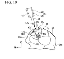
- the operation of opening the case cover 53 may be limited as a result of replacing the protuberance provided on the case cover 53 with the recessed portion, as a result of replacing the recessed portion provided on the steering-handlebar front cover 36a with the protuberance, or as a result of causing the bottom rear surface of the case cover 53 during attachment thereof to the vehicle body to come into butt-contact with the protuberance 53d provided on the upper portion of the steering-handlebar front cover 36a as shown in FIG. 10 .
- the personal digital assistant 45 can also output sounds by use of a speaker provided in the personal digital assistant 45 and can also output sounds by use of the communication between the personal digital assistant 45 and a head set (income) provided in a riding helmet.
- any one of radio communication and cable communication may be adopted.
- a radio-communication transmitting and receiving unit that adopts a short-distance radio communication standard such as Bluetooth (registered trademark) is provided in or connected to each of the personal digital assistant 45 and the target device.
- a short-distance radio communication standard such as Bluetooth (registered trademark)
- the means of communication is cable communication
- the charging of the personal digital assistant 45 may be carried out by a non-contact charging system such as a system utilizing electromagnetic induction between coils that are provided the respective terminal holder 51 and the vehicle body.
- the attachment structure of the personal digital assistant 45 to the motorcycle 1 includes: the terminal holder 51 that removably attaches the personal digital assistant 45 including the display screen 45a to the vehicle body, is provided separately from the vehicle body, and holds the personal digital assistant 45; and the holder support 47 that is provided integrally with the vehicle body and supports the terminal holder 51.
- the terminal holder 51 includes: the supporting legs 56 that are to be removably engaged with the holder support 47; and the connector cord 57 has the first end that is to be connected to the personal digital assistant 45 so that the first end is capable of supplying at least one of electric power and data to the personal digital assistant 45 from the vehicle-body-side.
- the supporting leg 56 includes: the cord insert hole 56e that holds the connector cord 57; and the holder-side connector 56d that connects the second end of the connector cord 57 (the second end on the opposite side of the first end) thereto.
- the holder support 47 includes the vehicle-body-side connector 47d that is removably connected to the holder-side connector 56d during engagement of the supporting legs 56.
- the personal digital assistant 45 since the personal digital assistant 45 is attached to the vehicle in a state where the personal digital assistant 45 is held to the terminal holder 51 that is provided separately from the vehicle body, personal digital assistants 45 which are different in the size or the type thereof can be attached to the vehicle by only selecting a terminal holder 51 so as to correspond to the personal digital assistant 45.
- the above-mentioned personal digital assistant attachment structure configures the lock mechanism 60 that is between the holder support 47 and the supporting leg 56 and limits the supporting leg 56 engaged with the holder support 47 from being removed therefrom, it is possible to prevent the personal digital assistant 45 from unintentionally dropping off and from being stolen in a state of being attached to the vehicle body.
- a plurality of the supporting legs 56 (one pair) is provided, the cord insert hole 56e is provided in one of the supporting legs 56, and the lock mechanism 60 is provided between the holder support 47 and the other of the supporting legs 56 in which the cord insert hole 56e is not provided. Therefore, a cord-wiring path is easily ensured in one of the supporting legs 56, and the lock mechanism 60 can be configured by effectively utilizing a space around the other of the supporting legs 56 in which the cord insert hole 56e is not provided.
- the supporting legs may be configured so that a cord holder is provided in at least one of the supporting legs 56 and a lock mechanism is provided around at least one of the other supporting legs.
- the supporting legs 56 are is formed in a rod shape, are inserted in the holder support 47 in the longitudinal direction thereof, and have the narrow portion 58 on the intermediate portion in the longitudinal direction.
- the holder support 47 includes the fork advance-retreat mechanism 59 that causes the fork member 59a to move forward and backward in the direction orthogonal to the longitudinal direction and causes the fork member 59a to be engaged with and disengaged from the narrow portion 58.
- the terminal holder 51 includes: the case body 52 that is integrally with the supporting legs 56 and can accommodate the personal digital assistant 45 therein; the spacer 55 that is selected so as to correspond to the personal digital assistant 45 and is accommodated in the case body 52; the case cover 53 that covers the opening 52a of the case body 52; and the hinge 54 that pivotally supports the case cover 53 to be openable and closable with respect to the case body 52.
- the case cover 53 includes: the window 53a that allows the display screen 45a of the personal digital assistant 45 to be exposed to the outside of the holder; and the protuberance 53c that is engaged with the steering handlebar cover 36 in a state where the case body 52 is closed during attachment of the terminal holder 51 to the vehicle body and limits the opening operation thereof.
- the display screen 45a of the personal digital assistant 45 is visible from the outside of the holder during attachment of the terminal holder 51 to the vehicle body, and a structure that limits the operation of opening the case cover 53 can be simply configured.
- the protuberance 53d is provided on the steering handlebar cover 36 that is provided at the attachment position of the personal digital assistant 45, and the protuberance is engaged with the case cover 53 in a state where the case body 52 is closed at the time of attachment of the terminal holder 51 and limits the operation of opening the case cover 53.
- the terminal holder 51 includes the packing 53b that is along the inner circumferential edge of the window 53a of the case cover 53 so as to come into tight contact with the periphery of the display screen 45a of the personal digital assistant 45 disposed inside the case body 52 when the case cover 53 is closed.
- the light receiver 45b that is used to capture an image of the front of the vehicle is provided on the front surface of the personal digital assistant 45 during attachment thereof to the vehicle body, and the exposed hole 52b that allows the light receiver 45b to be exposed to the front of the vehicle is provided on the terminal holder 51.
- the operation of the personal digital assistant 45 and the vehicle can be controlled based on image information of the front of the vehicle which is obtained by the light receiver 45b.
- the embodiment is particularly different from the first embodiment in that a terminal holder 151 is provided instead of the right and left supporting legs 56.
- the terminal holder includes a supported portion 156 that is formed in a plate shape such that the case body 52 and the lower edge of the case cover 53 extend downward during attachment thereof to the vehicle.
- the holder support 47 includes a supported portion (not shown in the figure) into which the plate-shape supported portion 156 of the terminal holder 151 is inserted in the direction along the surface of the supported portion 156, and the supported portion holds it.
- a slit-shaped insertion hole long in the right and left is formed on the upper portion of the steering-handlebar front cover 36a.
- the supported portion 156 of the terminal holder 151 reaches the holder support 47 provided inside the cover through the insertion hole.
- a manual type shutter (not shown in the figure) capable of watertightly sealing the insertion hole is provided on the insertion hole.
- the terminal holder 151 includes the case body 52, the case cover 53, the hinge 54, and the spacer 55.
- extension portions extending downward are provided on the lower edges of the case body 52 and the case cover 53 during attachment thereof to the vehicle, both extension portions overlap each other when the case cover 53 is closed, and the supported portion 156 is thereby formed.
- the supported portion 156 is inserted into the holder support 47 along the plugging direction.
- the connector cord 57 is held inside the portion (the left portion in the drawing) close to the terminal-side connector 57b of the supported portion 156.
- Reference numeral 156e in the drawing indicates a cord clip that holds the connector cord 57 inside the supported portion 156.
- the holder-side connector 56d is provided at the lower end of the supported portion 156 at the left portion thereof during attachment thereof to the vehicle.
- the exposed hole 52b which is not shown in the figure and corresponds to the light receiver 45b of the personal digital assistant 45 is provided on the terminal holder 151.
- Hole portions 158 are provided on, for example, the right and left portions of the front and back surfaces of the supported portion 156 during attachment thereof to the vehicle, and pins 159a provided in the holder support 47 are engaged with the hole portions.
- Pin advance-retreat mechanisms 159 are provided in the respective right and left portions of the holder support 47, the advance-retreat mechanisms allow the right and left pins 159a to be respectively fitted into the right and left hole portions 158 of the supported portion 156 in accordance with, for example, insertion of the supported portion 156 thereinto.
- the forward and backward directions of the right and left pins 159a are the direction orthogonal to the front and back surfaces (thickness direction of the terminal holder 151).
- the configuration and operation of the pin advance-retreat mechanism 159 are similar to the configuration and operation of the fork advance-retreat mechanism 59.
- the above right and left hole portions 158 and the pin advance-retreat mechanisms 159 constitutes a lock mechanism 160 that limits the supported portion 156 inserted into the holder support 47 from being removed from the holder support 47 (furthermore, removal of the terminal holder 151 attached to the vehicle body from the vehicle body).
- personal digital assistants 45 which are different in the size or the type thereof can be attached to the vehicle by only selecting the terminal holder 151 so as to correspond to the personal digital assistant 45, and charging of the personal digital assistant 45 or displaying a variety of vehicle information can be carried out.
- the supported portion 156 of the terminal holder 151 is formed in a plate shape, is inserted into the holder support 47 in the direction along the top surface and the back surface (the extending direction of the supported portion 156), and has the hole portions 158 at predetermined positions of the top surface and the back surface.
- the holder support 47 has the pin advance-retreat mechanism 159 that causes the pin 159a to move forward and backward in the direction orthogonal to the top surface and the back surface and is used to carry out the attachment of the pins 159a to the hole portions 158 and the removal thereof from the hole portions 158.
- the hole portions 158 and the pin advance-retreat mechanism 159 constitute the lock mechanism 160.
- the lock mechanism 160 having a simplified configuration can be provided.
- the invention is not limited to the above-mentioned embodiments.
- the personal digital assistant 45 senses a pedestrian by image-capturing in, for example, a state of extremely low speed
- the personal digital assistant may produce a sound by a speaker or lamp lighting and thereby alert the pedestrian who approaches the vehicle.
- the speaker or the lamp may be provided on the personal digital assistant 45 or mounted on the vehicle.
- the personal digital assistant of the invention is not limited to the smartphone of the above-described embodiments and may be a relatively large-scaled tablet device.
- the saddle-ride vehicle means general vehicles on which a driver straddles and is seated, such as a motorcycle (including a motorized bicycle and a scooter-type vehicle), a three wheeled vehicle (including a vehicle provided with front-two wheels and rear-single wheel in addition to a vehicle provided with a front-single wheel and rear-two wheels), a four-wheeled vehicle, or a vehicle provided with a motor serving as an internal combustion engine.
- a motorcycle including a motorized bicycle and a scooter-type vehicle
- a three wheeled vehicle including a vehicle provided with front-two wheels and rear-single wheel in addition to a vehicle provided with a front-single wheel and rear-two wheels
- a four-wheeled vehicle or a vehicle provided with a motor serving as an internal combustion engine.
Landscapes
- Engineering & Computer Science (AREA)
- Mechanical Engineering (AREA)
- Fittings On The Vehicle Exterior For Carrying Loads, And Devices For Holding Or Mounting Articles (AREA)
- Signal Processing (AREA)
- Lock And Its Accessories (AREA)
- Electric Propulsion And Braking For Vehicles (AREA)
Abstract
Description
- The present invention relates to a personal digital assistant attachment structure for a saddle-ride vehicle such as a motorcycle.
- This application claims priority from Japanese Patent Application No.
2012-051592 filed on March 8, 2012 - Patent Document 1 discloses that, in a motorcycle to which a personal digital assistant such as a portable telephone is removably attached, a structure in which a recess-shaped terminal holder is provided which holds the personal digital assistant in an upright state in front of a meter unit provided at the center of the bar handle.
- In the disclosure of Patent Document 1, as a result of providing this structure, radio communication between the personal digital assistant and the motorcycle, displaying a variety of vehicle information on the personal digital assistant, and non-contact charge of the personal digital assistant can be carried out.
- [Patent Document 1]Japanese Unexamined Patent Application, First Publication No.
2003-137161 - However, in the aforementioned related art, the recess-shaped terminal holder is provided in front of the meter unit.
- Consequently, there is a problem in that the holder is limited to the attachment of a predetermined size of a personal digital assistant or a predetermined type thereof.
- Additionally, in the case where the personal digital assistant does not correspond to a motorcycle being used, there is a problem in that communicating and charging of the personal digital assistant cannot be carried out.
- For this reason, the invention provides the personal digital assistant attachment structure for a saddle-ride vehicle, in which a personal digital assistant can be attached to a terminal holder provided on the vehicle body regardless of the size or the type of the personal digital assistant, and communicating and charging of the personal digital assistant can be carried out.
- A personal digital assistant attachment structure according to one aspect of the invention, which serves as a means to solve the above-mentioned problem and is used for a saddle-ride vehicle, is a personal digital assistant attachment structure for a saddle-ride vehicle, removably attaching a personal digital assistant including a display screen to a vehicle body. The attachment structure includes: a terminal holder that includes a connector cord and a supported portion, is provided separately from the vehicle body, and holds the personal digital assistant, the connector cord including a first end and a second end different from the first end, the first end being connected to the personal digital assistant so that the first end is capable of supplying at least one of electric power and data to the personal digital assistant from the vehicle body, the supported portion including a cord holder and a holder terminal, the cord holder holding the connector cord, the holder terminal being connected to the second end of the connector cord; and a holder support that is provided integrally with the vehicle body, is removably engaged with the supported portion and to support the terminal holder, and includes a vehicle-body-side terminal, the vehicle-body-side terminal being removably connected to the holder terminal during engagement of the supported portion.
- Particularly, the saddle-ride vehicle means general vehicles on which a driver straddles and is seated, such as a motorcycle (including a motorized bicycle and a scooter-type vehicle), a three wheeled vehicle (including a vehicle provided with front-two wheels and rear-single wheel in addition to a vehicle provided with a front-single wheel and rear-two wheels), or a four-wheeled vehicle.
- It may have a lock mechanism that is provided between the holder support and the supported portion, and limits the supported portion engaged with the holder support from being removed from the holder support.
- It may be that a plurality of supported portions are provided at the holder support, the cord holder is provided in at least one of the supported portions, and the lock mechanism is provided between the holder support and at least one of the supported portions at which the cord holder is not provided.
- It may be that the supported portion is formed in a rod shape, is inserted into the holder support in the longitudinal direction of the supported portion, and includes a narrow portion provided on an intermediate portion of the supported portion in the longitudinal direction, the holder support includes a fork advance-retreat mechanism that causes a fork member to move forward and backward in a direction orthogonal to the longitudinal direction and thereby causes the fork member to engage with and disengage from the narrow portion, and the lock mechanism is constituted of the narrow portion and the fork advance-retreat mechanism.
- It may be that the supported portion is formed in a plate shape, is inserted into the holder support in a direction along a top surface and a back surface of the supported portion, and has a hole portion formed at a predetermined position on the top surface and the back surface, the holder support includes a pin advance-retreat mechanism that is used to cause a pin to move forward and backward in a direction orthogonal to the top surface and the back surface, and attach the pin to the hole portion and remove the pin from the hole portion, and the lock mechanism is constituted of the hole portion and the pin advance-retreat mechanism.
- The personal digital assistant attachment structure for a saddle-ride vehicle according to one aspect of the invention may further include a vehicle-body-side fixation member provided at an attachment position of the personal digital assistant, wherein the terminal holder further includes: a case capable of accommodating the personal digital assistant; a spacer that is selected so as to correspond to the personal digital assistant and is accommodated in the case; a cover that covers an opening of the case; and a hinge that pivotally supports the cover so to be openable and closable with respect to the case, the supported portion is formed integrally with the terminal holder, and the cover has: a window that exposes a display screen of the personal digital assistant to outside of a holder; and an engagement portion that is to be engaged with the vehicle-body-side fixation member in a state where the case is closed during attachment of the terminal holder to the vehicle body and thereby limits an operation of opening the cover.
- The personal digital assistant attachment structure for a saddle-ride vehicle according to one aspect of the invention may further include a vehicle-body-side fixation member provided at an attachment position of the personal digital assistant, wherein the terminal holder further includes: a case capable of accommodating the personal digital assistant; a spacer that is selected so as to match to the personal digital assistant and is accommodated in the case; a cover that covers an opening of the case; and a hinge that pivotally supports the cover so to be openable and closable with respect to the case, the supported portion is formed integrally with the terminal holder, and an engagement portion that is to be engaged with the cover in a state where the case is closed during attachment of the terminal holder and thereby limits an operation of opening the cover is provided on the vehicle-body-side fixation member.
- It may be that the terminal holder includes a seal that is provided along an inner circumferential edge of a window of the cover so as to come into tight contact with the periphery of a display screen of the personal digital assistant inside the case when the cover is closed.
- It may be that a light receiver that is used to capture an image of a front of the vehicle is provided on a front surface of the personal digital assistant during attachment thereof to the vehicle body, and an exposed hole that allows the light receiver to be exposed to the front of the vehicle is provided on the terminal holder.
- According to the aspect of the invention, as a result of holding the personal digital assistant on the terminal holder that is separated from a vehicle body, attaching the terminal holder to the vehicle, and only causing the terminal holder to correspond to personal digital assistants which are different in the size or the type thereof, it is possible to attach the personal digital assistant to the vehicle.
- Additionally, as a result of using the supported portion of the terminal holder and the holder support of the vehicle as a connector and connecting the personal digital assistant to a battery or a controller of the vehicle, it is possible to charge the personal digital assistant and it is possible to display a variety of vehicle information.
- According to the aspect of the invention, it is possible to prevent the personal digital assistant from unintentionally dropping off and from being stolen in a state of being attached to the vehicle body.
- According to the aspect of the invention, a cord-wiring path is easily ensured in one of the supported portions, and the lock mechanism can be configured by effectively utilizing a space around the supported portion other than the supported portion in which the cord-wiring path is ensured.
- According to the aspect of the invention, a lock mechanism having a simplified configuration can be provided.
- According to the aspect of the invention, during attachment of the terminal holder to the vehicle body, the display screen of personal digital assistant is visible from the outside of the holder, and it is possible to easily configure a constitution that limits an operation of opening the cover.
- Additionally, as a result of replacement of the spacer, it is possible to simply and inexpensively accommodate the various types of personal digital assistant in the terminal holder.
- According to the aspect of the invention, it is possible to prevent water, dust, or the like from entering the inside of the terminal holder through the window.
- According to the aspect of the invention, the operation of the personal digital assistant and the vehicle can be controlled based on image information of the front of the vehicle which is obtained by the light receiver.
-
-
FIG. 1 is a left side view showing a motorcycle according to the first embodiment of the invention. -
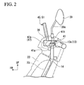
FIG. 2 is a left side view showing the periphery of a bar handle of the above-mentioned motorcycle. -
FIG. 3 is an anterior view showing the periphery of the aforementioned bar handle. -
FIG. 4 is a top view showing the periphery of the aforementioned bar handle. -
FIG. 5 is a left side view including a partial cross section of the periphery of a holder support that supports a terminal holder used to attach a personal digital assistant to the aforementioned motorcycle. -
FIG. 6 is a top view showing the periphery of the aforementioned holder support. -
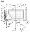
FIG. 7 is a front view showing the aforementioned terminal holder. -
FIG. 8 is a front view showing the aforementioned terminal holder in an exploded state. -
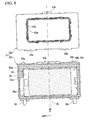
FIG. 9 is a front view showing a terminal holder according to the second embodiment of the invention. -
FIG. 10 is a left side view showing the periphery of a modified example of the aforementioned holder support and corresponding toFIG. 5 . - Hereinafter, a saddle-ride vehicle according to an embodiment of the invention will be described with reference to drawings.
- Particularly, directions described below such as front, back, left, and right, and the like are identical to the directions of a vehicle described below unless otherwise specifically described.
- Additionally, the arrow FR indicating the front direction of the vehicle, the arrow LH indicating the left direction of the vehicle, and the arrow UP indicating the upper direction of the vehicle are suitably shown in the drawings used for explanation described below.
- A motorcycle 1 shown in
FIG. 1 is a scooter-type vehicle having alow floor 2, rotationally drives arear wheel 5 that is pivotally supported by awheel shaft 5a provided at a rear end of arear swing arm 3 due to rotational power of an electric motor 4 built in therear swing arm 3, and thereby runs. - A battery case 6 is provided under the
low floor 2, and the battery case accommodates a high voltage battery (not shown in the figure) of 48 to 72V in voltage and serves as a power supply for the electric motor 4, and BMU (Battery Managing Unit, not shown in the figure) that controls discharging and charging of the high voltage battery. - A vehicle body frame 7 of the motorcycle 1 includes a
head pipe 8 that is on the front end portion thereof and is backward inclined with respect to the vertical direction. - A
steering stem 9 is rotatably supported by thehead pipe 8. - An upper end of right and
left front forks 12 is supported by thesteering stem 9, and afront wheel 11 is pivotally supported by the lower end of the right and left front forks. - The
steering stem 9 includes a stem pipe (not shown in the figure) that is inserted into thehead pipe 8 from the lower side thereof. - A
steering bar handle 13 is rotatably and integrally attached to the stem pipe via ahandle stem 14 at the protruding portion that upwardly protrudes from thehead pipe 8 at the stem pipe. - A
seat 15 on which an occupant is to be seated is provided rearward of thebar handle 13 with a straddle space M interposed therebetween. - The
rear swing arm 3 has a front end portion that is supported by a pivot portion located at a lower portion of a vehicle body so as to be capable of swinging in the vertical direction. - Regarding the
rear swing arm 3, a cantilever type such that therear wheel 5 is pivotally supported by only an arm provided at the left side in the vehicle width direction is adopted. - The rear end of the left arm of the
rear swing arm 3 is supported by the left-side rear end of the vehicle body frame 7 with arear cushion 16 interposed therebetween. - In the
rear swing arm 3, the electric motor 4, a centrifugal clutch (not shown in the figure) serving as a cut mechanism of rotating drive force, a reduction gear mechanism, and a PDU 17 (Power Drive Unit) that controls the output of the electric motor 4 are concentratedly arranged. - An ECU 18 (electronic control unit) is provided integrally with the PDU 17.
- The vehicle body frame 7 of the motorcycle 1 is covered with a
vehicle body cover 21 made of a synthetic resin material. - The
vehicle body cover 21 includes: afront cover 22 that covers the front of the peripheral portion of thehead pipe 8; aleg shield 23 that covers the rear of the peripheral portion of thehead pipe 8; thelow floor 2 on which the feet of the occupant seated on theseat 15 are mounted, which extends from the lower portion of theleg shield 23 to the rear, and which covers the battery case 6 from above; a pair of right and left floor side covers 24 that droop from the external side of thelow floor 2; an undercover 25 that connects the lower edges of the paired right and left floor side covers 24; so as to cover the front of a lower space of theseat 15; a seat-front-lower-portion cover 26 that is provided upright from the rear end of thelow floor 2; a pair of right and left side covers 27 that extend to the rear of the outside portion of the seat-front-lower-portion cover 26 so as to cover the side portions of the lower space of theseat 15; and arear cover 28 that extends to the rear of the right and left side covers 27 so as to cover therear wheel 5 from above. - A
lid 29 that opens or closes a charging port of a high voltage battery provided inside the battery case 6 is provided on theleft side cover 27. - An
article storage box 31 which is openable and closable by theseat 15 is disposed in the lower space of theseat 15. - A
low voltage battery 32 of 12V is disposed at a bottom portion thearticle storage box 31. - A
seat sensor 33 that detects the occupant seated thereon is placed at a position close to the top surface of the seat 15 (seating surface). - A
sound emitter 34 is disposed inside thefront cover 22, and the sound emitter alerts someone that the own vehicle approaches the periphery thereof at extremely low speed. - A main
key switch 35 including a key cylinder is disposed at the right side of theleg shield 23. - As shown in
FIGS. 2 to 4 , left and right handle grips 13a are provided at both right and left sides of thebar handle 13. - The center portion of the bar handle 13 is curved in a U-shape so as to protrude downward in a front view.
- Except for the left and right handle grips 13a, the bar handle 13 is covered with a steering
handlebar cover 36 that constitutes part of thevehicle body cover 21. - The line CL in the drawings indicates the center line that defines the right and left of the vehicle body.
- The steering
handlebar cover 36 is divisionally configured by: a steering-handlebar front cover 36a that covers the front of thebar handle 13; and a steering-handlebarrear cover 36b that covers the rear of thebar handle 13. - The line K in the drawings indicates the boundary line between the upper surface of the steering-
handlebar front cover 36a and the upper surface of the steering-handlebarrear cover 36b. - A
meter unit 37 including a speedometer or the like is provided on the center portion between the right and left of the steering-handlebarrear cover 36b. -
Exposed holes 38 are provided on both the upper-right and upper-left sides of the steering-handlebar front cover 36a, the exposed holes allow mirror-fastening bosses 41 b to be exposed to the outside of the cover, and the bosses are provided inside the steeringhandlebar cover 36. - The steering
handlebar cover 36 is fixedly attached to the vehicle body, and a tool is necessary for attachment and replacement of the steeringhandlebar cover 36. - In the
steering handlebar cover 36,lever holders 41 that supportbrake levers 41a are attached to the positions close to the base ends of the respective left and right handle grips 13a. - The mirror-
fastening bosses 41b that tighten mirror stays 39a provided at the right and leftrearview mirrors 39 are provided on the respective right and leftlever holders 41 by integral molding or the like. - Operation switches 42 of a lamp unit or the like are provided on both the upper-right and upper-left sides of the steering-handlebar
rear cover 36b. - The center portion is between the right and left of the steering-handlebar
rear cover 36b, themeter unit 37 or the like are provided on the center portion, theswitches 42 or the like are provided on both the right and left sides portions, and trailing edge configurations between the center portion and both the right and left sides portions iscurved portions 43 having a projected shape that protrudes forward in a top view. - A
holder support 47 that supports aterminal holder 51 is provided in the steering-handlebar front cover 36a, and the terminal holder holds (accommodates) a personaldigital assistant 45 therein. - As the personal
digital assistant 45, for example, a smartphone (a multifunction portable telephone provided with a PDA function) is adopted. - The personal
digital assistant 45 includes a relatively large-scaleddisplay screen 45a serving as a touch panel. - The personal
digital assistant 45 can display an internet screen and a navigation screen using a GPS on thedisplay screen 45a. - Furthermore, as a result of connecting the personal
digital assistant 45 to the ECU 18 or the BMU, a variety of vehicle information of the motorcycle 1, information of a residual amount of battery of a high voltage battery inside the battery case 6, or the like can be displayed on thedisplay screen 45a. - The
holder support 47 is fixed integrally to the bar handle 13 by, for example, tightening or the like. - As shown in
FIGS. 5 and 6 , theholder support 47 includes a pair of right and left leg supports 47a that hold a pair of right and left supportinglegs 56 of theterminal holder 51 in a state where the paired right and left supportinglegs 56 are inserted into the holder support. - A pair of right and left
foot insertion holes 47b are formed on each of the upper-right side and upper-left side of the steering-handlebar front cover 36a. - The right and left supporting
legs 56 of theterminal holder 51 are inserted through the foot insertion holes 47b and are fixed to the right and left leg supports 47a of theholder support 47 which are provided inside the steering-handlebar front cover 36a. - For example, a
manual type shutter 47c capable of watertightly sealing the right and leftfoot insertion holes 47b is individually provided on each of the right and leftfoot insertion holes 47b. - As shown in
FIG. 7 , theterminal holder 51 is formed in a case shape which is separated from the vehicle body of the motorcycle 1, accommodates and holds the personaldigital assistant 45 thereinside, and can removably attach the personaldigital assistant 45 to the vehicle body. - The
terminal holder 51 is formed in a rectangular thick plate shape slightly larger than the personaldigital assistant 45 so as to be able to accommodate the personaldigital assistant 45 that is formed in a rectangular thick plate shape. - As shown in
FIGS. 2 to 4 , the personaldigital assistant 45 and theterminal holder 51 are arranged in the position where the long side of the rectangle is parallel to the horizontal direction of the motorcycle 1 and both surfaces in the thickness direction of the personaldigital assistant 45 and theterminal holder 51 are tilted slightly forward with respect to the vertical direction in a state of being directed to the front-back direction of the motorcycle 1 during attachment thereof to the vehicle body. - The
display screen 45a of the personaldigital assistant 45 is located to face the rear side (occupant side). - As shown in
FIGS. 7 and8 , theterminal holder 51 includes: acase body 52 that is formed in a tray shape; acase cover 53 that covers anopening 52a provided on thecase body 52; ahinge 54 that openably and closably supports the case cover 53 with respect to thecase body 52; aspacer 55 that is selected so as to correspond to the personaldigital assistant 45 and is accommodated in thecase body 52; and the paired right and left supportinglegs 56 that are provided integrally with thecase body 52. - The
case body 52 and the case cover 53 are made of, for example, a commodity plastic for vehicle use such as a PP resin or an ABS resin. - At least one of the
case body 52 and the case cover 53 may be made of light metals such as aluminum alloys. - The
case body 52 is attached to the vehicle body so that theopening 52a in the thickness direction thereof is directed to diagonal upper rearward (occupant side). - The measurements of the interior of the
case body 52 are larger than and deeper than the outer sizes of the personaldigital assistant 45. - The personal
digital assistant 45 and thespacer 55 that is selected so as to correspond to the size or the type of the personaldigital assistant 45 are accommodated in thecase body 52 in a state of being positionally-fixed. - As shown in
FIG. 3 , alight receiver 45b is provided on the front surface of the personaldigital assistant 45 which is directed to the front of the vehicle (surface on the opposite side of thedisplay screen 45a) during attachment thereof to the vehicle. The light receiver and an imaging device that is provided in the housing of the personaldigital assistant 45 constitute an imaging unit. - The
light receiver 45b is arranged so that the optical axis of the lens of thelight receiver 45b is parallel to the thickness direction of the personaldigital assistant 45. - An exposed
hole 52b that allows thelight receiver 45b to be exposed to the outside of the holder (front of the vehicle) is formed at the portion of thecase body 52 which faces thelight receiver 45b. - In a state where the personal
digital assistant 45 and theterminal holder 51 are attached to the vehicle body, the personaldigital assistant 45 can capture an image of the front of the vehicle as an image through the exposedhole 52b. - In the case where a lamp (flash) is placed next to the
light receiver 45b, the exposedhole 52b also allows the lamp to be exposed to the outside of the holder. - The exposed
hole 52b may be provided on a plurality of portions so as to correspond to a plurality of kinds of the personaldigital assistants 45. - As shown in
FIGS. 7 and8 , after the case cover 53 is formed in a plate shape having the size equal to that of theopening 52a of thecase body 52, the case cover is formed in a frame shape having awindow 53 a that is formed by cutting off the inner-periphery of the plate-shaped body. - The
window 53a is provided on the region that faces thedisplay screen 45a of the personaldigital assistant 45 which is accommodated in the case body 52 (inside the terminal holder 51). - The
display screen 45a of the personaldigital assistant 45 which is accommodated in thecase body 52 is exposed to the outside of the holder through thewindow 53a, so the occupant can look at thedisplay screen 45a. - A seal member (not shown in the figure) is provided at the portion that faces the fringe of the
opening 52a of thecase body 52 of thecase cover 53. The seal member comes into watertight contact with the fringe of theopening 52a when theopening 52a is closed. - The
hinge 54 includes: hingereceivers 54a that are provided on the upper edge of thecase body 52 during attachment thereof to the vehicle body and are formed by, for example, integral molding; hingearms 54b that are provided to correspond to thehinge receivers 54a at the upper edge of the case cover 53 during attachment thereof to the vehicle body and are formed by, for example, integral molding; and ahinge shaft 54c that penetrates through thehinge receivers 54a and thehinge arms 54b along the upper edges of thecase body 52 and the case cover 53 during attachment thereof to the vehicle body (along the horizontal direction during attachment thereof to the vehicle body). - It is preferable that the
spacer 55 be formed of a member that is lightweight and inexpensive and has cushioning characteristics, is easy to process, and has shape-retaining characteristics such as urethane foam or synthetic rubber. - It is preferable that the
spacer 55 is an integrally molded product; however, it may be partially divided or exchangeable. -
Reference numeral 55a in the drawings indicates a recessed portion that accommodates a terminal-side connector 57b to be connected to the personaldigital assistant 45. - The right and left supporting
legs 56 are formed parallel to the front and back surfaces of theterminal holder 51 during attachment thereof to the vehicle, formed in a rod shape that extends in the direction parallel to the short side of the rectangular configuration, and inserted into the right and left leg supports 47a of theholder support 47 in the longitudinal direction thereof. - The insertion direction of the right and left supporting
legs 56 is a plugging direction of the terminal holder 51 (the personal digital assistant 45) into the vehicle body. - Each of the right and left supporting
legs 56 includes: a cylindrical legmain body 56a; and a fixingplate 56b that is formed in a plate shape, is disposed orthogonal to the cylinder axis of the legmain body 56a, and is secured to the upper end of the legmain body 56a during attachment thereof to the vehicle. - By suitably using synthetic resin materials, light alloy metals and a stainless steel, or the like, the leg
main body 56a and the fixingplate 56b are formed. - The fixing
plate 56b is fixed to the lower edge of thecase body 52 during attachment thereof to the vehicle By use of, for example, rivets 56c or the like having waterproofness. - The right and left supporting
legs 56 may be a folding-type leg, and the personaldigital assistant 45 and theterminal holder 51 may be easily portable in a state where the personaldigital assistant 45 is accommodated in theterminal holder 51. - A
cord insert hole 56e is provided inside of one of the right and left supporting legs 56 (the supporting leg which is located at the position close to the terminal-side connector 57b, and the left supporting leg in the drawing) and aconnector cord 57 is held therein. - The upper end of the
connector cord 57 during attachment thereof to the vehicle extends to the inside of theterminal holder 51 and is connected to the terminal-side connector 57b. - Furthermore, a
spiral cord 57a is formed at the upper end. - The lower end of the
connector cord 57 during attachment thereof to the vehicle is connected to a holder-side connector 56d that is provided on the end portion of the left supporting leg 56 (the lower end of theleft supporting leg 56 during attachment thereof to the vehicle). - The lower end of the
connector cord 57 during attachment thereof to the vehicle is fixedly held by theleft supporting leg 56; on the other hand, both the terminal-side connector 57b and the upper end of theconnector cord 57 during attachment thereof to the vehicle can be exchanged so as to correspond to the personaldigital assistant 45. -
Reference numeral 57c in the drawings indicates an intermediate connector that is used to be able to separate the intermediate portion of theconnector cord 57 therefrom. - The
left supporting leg 56 may be attachable to and detachable from thecase body 52 and theleft supporting leg 56 and theconnector cord 57 may be collectively exchangeable. - As shown in
FIG. 5 , as theleft supporting leg 56 is inserted into theleft leg support 47a of theholder support 47, the holder-side connector 56d is connected to a vehicle-body-side connector 47d that is provided in theleft leg support 47a. - For this reason, during attachment of the personal
digital assistant 45 and theterminal holder 51 to the vehicle body, the personaldigital assistant 45 and theterminal holder 51 are electrically connected to a main harness or the like of the motorcycle 1, the personaldigital assistant 45 obtains a variety of information from the ECU 18 or the BMU, and electric power of thelow voltage battery 32 or the like can be used to charge the personaldigital assistant 45. -
Reference numeral 47e in the drawings indicates, for example, a waterproof seal that is fitted onto the inner peripheral face theleft leg support 47a and is formed in a ring shape. - The
waterproof seal 47e may be fitted onto the outer peripheral face of theleft supporting leg 56. In this case, thewaterproof seal 47e is less likely to drop in theleft leg support 47a. - A
narrow portion 58 is provided on the intermediate portion in the longitudinal direction of the other of the right and left supporting legs 56 (the right supporting leg shown in the drawings), and the narrow portion is to be engaged with afork member 59a provided in theholder support 47. - As seen in the direction (e.g., the thickness direction of the terminal holder 51) orthogonal to the insertion direction (the plugging direction) of the
right supporting leg 56 into theright leg support 47a, thenarrow portion 58 includes semicircular recessedportions 58a that are formed on both edges of theright supporting leg 56 in the direction orthogonal to the insertion direction. - A fork advance-
retreat mechanism 59 is provided in theright leg support 47a of theholder support 47, and the fork advance-retreat mechanism causes thefork member 59a having two forks to engage with thenarrow portion 58 of theright supporting leg 56 in accordance with, for example, the insertion of theright supporting leg 56 thereinto. - The fork advance-
retreat mechanism 59 causes thefork member 59a to move forward and backward in the thickness direction of the terminal holder 51 (the direction orthogonal to the plugging direction) by, for example, driving power of a solenoid. - The fork advance-
retreat mechanism 59 causes thefork member 59a to move forward in accordance with, for example, the operation of insertion of theright supporting leg 56 and causes thefork member 59a to be engaged with thenarrow portion 58 of theright supporting leg 56. - The
narrow portion 58 and the fork advance-retreat mechanism 59 constitutes alock mechanism 60 that limits the supportingleg 56 inserted into theleg support 47a from being removed from theleg support 47a (furthermore, removal of theterminal holder 51 attached to the vehicle body from the vehicle body). - It is only necessary that at least one of the combination of the
left supporting leg 56 and theleft leg support 47a and the combination of theright supporting leg 56 and theright leg support 47a be provided in thelock mechanism 60. - At this time, the
connector cord 57 and thecord insert hole 56e are provided in the other supportingleg 56 on which thelock mechanism 60 is not provided. - Because of this, a cord-wiring path is easily ensured in the other supporting
leg 56 and thelock mechanism 60 is easily formed on the periphery of the said one supportingleg 56 in which theconnector cord 57 and thecord insert hole 56e are not provided. - In other cases where a space or the like used to arrange the
lock mechanism 60 therein can be ensured, thelock mechanism 60 may be arranged at any one of the right and left supportinglegs 56. - As a result of a predetermined operation or the like of, for example, the main
key switch 35, the fork advance-retreat mechanism 59 causes thefork member 59a that is engaged with thenarrow portion 58 to move backward. - Therefore, it is possible to remove (detach) the
terminal holder 51 attached to the vehicle body from the vehicle body. - A system may be adopted which causes the
fork member 59a to be engaged with the supportingleg 56 by a predetermined operation or the like of the mainkey switch 35. - Engagement portion of the supporting
leg 56 with which thefork member 59a is to be engaged is not limited to thenarrow portion 58 that is obtained by depressing a side edge thereof so that thefork member 59a is engaged with the side edge. The engagement portion may be a depressed portion or a hole portion which causes thefork member 59a to engage with and disengage from thefork member 59a in the forward and backward direction. - With respect to the
terminal holder 51, as an operation of releasing the lock thereof which is carried out by thelock mechanism 60, the operation of the mainkey switch 35 is adopted. - However, there is the case of a keyless entry where a smart key system is adopted in the motorcycle 1 and a main switch operation or the like is activated based on ID certification or the like by radio communication between a user's portable key terminal and the motorcycle 1. In this case, a valid operation such as using the main switch or the like may be carried out as the operation of releasing the lock of removal of the
terminal holder 51. - At this time, as the key terminal, the personal
digital assistant 45 may be used. - A
packing 53b is attached to the inner surface of the case cover 53 (front surface, surface located at the position close to the case body 52), and the packing is formed in a frame shape that is along the inner circumferential edge of thewindow 53a as seen in the thickness direction of theterminal holder 51. - The
packing 53b is formed of, for example, a urethane foam material or the like and comes into watertight contact with the position close to the outer circumferential edge of thedisplay screen 45a of the personaldigital assistant 45 disposed in thecase body 52 when the case cover 53 is closed. - By means of this structure, water is prevented from entering the inside of the
terminal holder 51 through thewindow 53a in a state where the case cover 53 is closed. - In the case where the
window 53a is opened, even where thedisplay screen 45a of the personaldigital assistant 45 serves as a touch panel, it is possible to operate thedisplay screen 45a. - In the case where the
window 53a is sealed by a hard transparent member such as an acrylic plate, thedisplay screen 45a cannot be touched. - On the other hand, the degree of waterproofness of the
terminal holder 51 is high. - In the case where the
window 53a is sealed by a transparent film that is located adjacent to thedisplay screen 45a and in the case where thedisplay screen 45a is a pressure-sensitive touch panel, it is possible to operate thedisplay screen 45a, and a degree of waterproofness of theterminal holder 51 is high. - In the case where the
window 53a is sealed by a conductive transparent film that is located adjacent to thedisplay screen 45a, even in the case where thedisplay screen 45a of the personaldigital assistant 45 is an electrostatic touch panel, it is possible to operate thedisplay screen 45a, and a degree of waterproofness of theterminal holder 51 is high. - In the case where the
window 53a is sealed, the degree of freedom in application of thewindow 53a or the packing 53b to the personaldigital assistant 45 is high. - A
protuberance 53c is provided on the lower edge of the case cover 53 during attachment thereof to the vehicle body by, for example, integral molding, and the protuberance protrudes downward therefrom in the direction parallel to the supportinglegs 56. - In accordance with an operation of attaching the
terminal holder 51 to the vehicle body, and the protuberance limits the operation of opening thecase cover 53, theprotuberance 53c (engagement portion) is fitted into a recessedportion 36c that is provided on, for example, the upper portion of the steering-handlebar front cover 36a from above. - Accordingly, the operation of opening the case cover 53 is easily and reliably limited when the
terminal holder 51 is attached to the vehicle body. - In such opening-operation limiting mechanism, the operation of opening the case cover 53 may be limited as a result of replacing the protuberance provided on the case cover 53 with the recessed portion, as a result of replacing the recessed portion provided on the steering-
handlebar front cover 36a with the protuberance, or as a result of causing the bottom rear surface of the case cover 53 during attachment thereof to the vehicle body to come into butt-contact with theprotuberance 53d provided on the upper portion of the steering-handlebar front cover 36a as shown inFIG. 10 . - By eliminating the protuberance of the
terminal holder 51, the bulkiness of theterminal holder 51 while being carried is reduced. - The personal
digital assistant 45 can also output sounds by use of a speaker provided in the personaldigital assistant 45 and can also output sounds by use of the communication between the personaldigital assistant 45 and a head set (income) provided in a riding helmet. - As a means of communication between the personal
digital assistant 45 and the target device (the above-described ECU, BMU, head set, or the like), any one of radio communication and cable communication may be adopted. - In the case where the means of communication is radio communication, it is thought that a radio-communication transmitting and receiving unit that adopts a short-distance radio communication standard such as Bluetooth (registered trademark) is provided in or connected to each of the personal
digital assistant 45 and the target device. - In the case where the means of communication is cable communication, it is necessary to draw a wiring that connects the personal
digital assistant 45 to the target device; however, the personaldigital assistant 45 is easily charged by a vehicle-mounted battery. - The charging of the personal
digital assistant 45 may be carried out by a non-contact charging system such as a system utilizing electromagnetic induction between coils that are provided therespective terminal holder 51 and the vehicle body. - As described above, the attachment structure of the personal
digital assistant 45 to the motorcycle 1 according to the aforementioned embodiment includes: theterminal holder 51 that removably attaches the personaldigital assistant 45 including thedisplay screen 45a to the vehicle body, is provided separately from the vehicle body, and holds the personaldigital assistant 45; and theholder support 47 that is provided integrally with the vehicle body and supports theterminal holder 51. - The
terminal holder 51 includes: the supportinglegs 56 that are to be removably engaged with theholder support 47; and theconnector cord 57 has the first end that is to be connected to the personaldigital assistant 45 so that the first end is capable of supplying at least one of electric power and data to the personaldigital assistant 45 from the vehicle-body-side. - The supporting
leg 56 includes: thecord insert hole 56e that holds theconnector cord 57; and the holder-side connector 56d that connects the second end of the connector cord 57 (the second end on the opposite side of the first end) thereto. - The
holder support 47 includes the vehicle-body-side connector 47d that is removably connected to the holder-side connector 56d during engagement of the supportinglegs 56. - According to this configuration, since the personal
digital assistant 45 is attached to the vehicle in a state where the personaldigital assistant 45 is held to theterminal holder 51 that is provided separately from the vehicle body, personaldigital assistants 45 which are different in the size or the type thereof can be attached to the vehicle by only selecting aterminal holder 51 so as to correspond to the personaldigital assistant 45. - Moreover, as a result of using the supporting
leg 56 of theterminal holder 51 and theholder support 47 of the vehicle as connectors and connecting the personaldigital assistant 45 to a battery or a controller of the vehicle, charging of the personaldigital assistant 45 or displaying a variety of vehicle information can be carried out. - Furthermore, since the above-mentioned personal digital assistant attachment structure configures the
lock mechanism 60 that is between theholder support 47 and the supportingleg 56 and limits the supportingleg 56 engaged with theholder support 47 from being removed therefrom, it is possible to prevent the personaldigital assistant 45 from unintentionally dropping off and from being stolen in a state of being attached to the vehicle body. - Moreover, in the above-mentioned personal digital assistant attachment structure, a plurality of the supporting legs 56 (one pair) is provided, the
cord insert hole 56e is provided in one of the supportinglegs 56, and thelock mechanism 60 is provided between theholder support 47 and the other of the supportinglegs 56 in which thecord insert hole 56e is not provided. Therefore, a cord-wiring path is easily ensured in one of the supportinglegs 56, and thelock mechanism 60 can be configured by effectively utilizing a space around the other of the supportinglegs 56 in which thecord insert hole 56e is not provided. - In other cases where three or more
supporting legs 56 are provided, the supporting legs may be configured so that a cord holder is provided in at least one of the supportinglegs 56 and a lock mechanism is provided around at least one of the other supporting legs. - Furthermore, in the above-described personal digital assistant attachment structure, the supporting
legs 56 are is formed in a rod shape, are inserted in theholder support 47 in the longitudinal direction thereof, and have thenarrow portion 58 on the intermediate portion in the longitudinal direction. Theholder support 47 includes the fork advance-retreat mechanism 59 that causes thefork member 59a to move forward and backward in the direction orthogonal to the longitudinal direction and causes thefork member 59a to be engaged with and disengaged from thenarrow portion 58. As a result of configuring thelock mechanism 60 by thenarrow portion 58 and the fork advance-retreat mechanism 59, thelock mechanism 60 having a simplified configuration can be provided. - Additionally, in the aforementioned personal digital assistant attachment structure, the
terminal holder 51 includes: thecase body 52 that is integrally with the supportinglegs 56 and can accommodate the personaldigital assistant 45 therein; thespacer 55 that is selected so as to correspond to the personaldigital assistant 45 and is accommodated in thecase body 52; the case cover 53 that covers theopening 52a of thecase body 52; and thehinge 54 that pivotally supports the case cover 53 to be openable and closable with respect to thecase body 52. The case cover 53 includes: thewindow 53a that allows thedisplay screen 45a of the personaldigital assistant 45 to be exposed to the outside of the holder; and theprotuberance 53c that is engaged with the steeringhandlebar cover 36 in a state where thecase body 52 is closed during attachment of theterminal holder 51 to the vehicle body and limits the opening operation thereof. - Consequently, the
display screen 45a of the personaldigital assistant 45 is visible from the outside of the holder during attachment of theterminal holder 51 to the vehicle body, and a structure that limits the operation of opening the case cover 53 can be simply configured. - Furthermore, as a result of replacement of the
spacer 55, it is possible to simply and inexpensively accommodate the various types of personaldigital assistant 45 in theterminal holder 51. - Moreover, in the above-described personal digital assistant attachment structure, the
protuberance 53d is provided on the steeringhandlebar cover 36 that is provided at the attachment position of the personaldigital assistant 45, and the protuberance is engaged with the case cover 53 in a state where thecase body 52 is closed at the time of attachment of theterminal holder 51 and limits the operation of opening thecase cover 53. - For this reason, in addition to the above-mentioned actions and effects, the bulkiness of the
terminal holder 51 while being carried after theterminal holder 51 is removed from the vehicle body is reduced. - Additionally, in the aforementioned personal digital assistant attachment structure, the
terminal holder 51 includes thepacking 53b that is along the inner circumferential edge of thewindow 53a of the case cover 53 so as to come into tight contact with the periphery of thedisplay screen 45a of the personaldigital assistant 45 disposed inside thecase body 52 when the case cover 53 is closed. - By means of this structure, it is possible to prevent water, dust, or the like from entering the inside of the
terminal holder 51 through thewindow 53a. - Furthermore, in the above-described personal digital assistant attachment structure, the
light receiver 45b that is used to capture an image of the front of the vehicle is provided on the front surface of the personaldigital assistant 45 during attachment thereof to the vehicle body, and the exposedhole 52b that allows thelight receiver 45b to be exposed to the front of the vehicle is provided on theterminal holder 51. - Accordingly, the operation of the personal
digital assistant 45 and the vehicle can be controlled based on image information of the front of the vehicle which is obtained by thelight receiver 45b. - Next, the second embodiment of the invention will be described with reference to
FIG. 9 . - The embodiment is particularly different from the first embodiment in that a
terminal holder 151 is provided instead of the right and left supportinglegs 56. The terminal holder includes a supportedportion 156 that is formed in a plate shape such that thecase body 52 and the lower edge of the case cover 53 extend downward during attachment thereof to the vehicle. - Identical symbols are used for the constituent elements which are identical to those of the above-described embodiment, and the specific explanations thereof are omitted here.
- The
holder support 47 includes a supported portion (not shown in the figure) into which the plate-shape supportedportion 156 of theterminal holder 151 is inserted in the direction along the surface of the supportedportion 156, and the supported portion holds it. - A slit-shaped insertion hole long in the right and left (not shown in the figure) is formed on the upper portion of the steering-
handlebar front cover 36a. - Additionally, the supported
portion 156 of theterminal holder 151 reaches theholder support 47 provided inside the cover through the insertion hole. - For example, a manual type shutter (not shown in the figure) capable of watertightly sealing the insertion hole is provided on the insertion hole.
- The
terminal holder 151 includes thecase body 52, thecase cover 53, thehinge 54, and thespacer 55. - By integral molding, extension portions extending downward are provided on the lower edges of the
case body 52 and the case cover 53 during attachment thereof to the vehicle, both extension portions overlap each other when the case cover 53 is closed, and the supportedportion 156 is thereby formed. - The supported
portion 156 is inserted into theholder support 47 along the plugging direction. - The
connector cord 57 is held inside the portion (the left portion in the drawing) close to the terminal-side connector 57b of the supportedportion 156. -
Reference numeral 156e in the drawing indicates a cord clip that holds theconnector cord 57 inside the supportedportion 156. - The holder-
side connector 56d is provided at the lower end of the supportedportion 156 at the left portion thereof during attachment thereof to the vehicle. - The exposed
hole 52b which is not shown in the figure and corresponds to thelight receiver 45b of the personaldigital assistant 45 is provided on theterminal holder 151. -
Hole portions 158 are provided on, for example, the right and left portions of the front and back surfaces of the supportedportion 156 during attachment thereof to the vehicle, andpins 159a provided in theholder support 47 are engaged with the hole portions. - Pin advance-
retreat mechanisms 159 are provided in the respective right and left portions of theholder support 47, the advance-retreat mechanisms allow the right and leftpins 159a to be respectively fitted into the right and lefthole portions 158 of the supportedportion 156 in accordance with, for example, insertion of the supportedportion 156 thereinto. - The forward and backward directions of the right and left
pins 159a are the direction orthogonal to the front and back surfaces (thickness direction of the terminal holder 151). - The configuration and operation of the pin advance-
retreat mechanism 159 are similar to the configuration and operation of the fork advance-retreat mechanism 59. - The above right and left
hole portions 158 and the pin advance-retreat mechanisms 159 constitutes alock mechanism 160 that limits the supportedportion 156 inserted into theholder support 47 from being removed from the holder support 47 (furthermore, removal of theterminal holder 151 attached to the vehicle body from the vehicle body). - As described above, also in the personal digital assistant attachment structure of the vehicle according to the above-mentioned embodiment, similar to the first embodiment, personal
digital assistants 45 which are different in the size or the type thereof can be attached to the vehicle by only selecting theterminal holder 151 so as to correspond to the personaldigital assistant 45, and charging of the personaldigital assistant 45 or displaying a variety of vehicle information can be carried out. - Particularly, in the above-described personal digital assistant attachment structure, the supported
portion 156 of theterminal holder 151 is formed in a plate shape, is inserted into theholder support 47 in the direction along the top surface and the back surface (the extending direction of the supported portion 156), and has thehole portions 158 at predetermined positions of the top surface and the back surface. Theholder support 47 has the pin advance-retreat mechanism 159 that causes thepin 159a to move forward and backward in the direction orthogonal to the top surface and the back surface and is used to carry out the attachment of thepins 159a to thehole portions 158 and the removal thereof from thehole portions 158. Thehole portions 158 and the pin advance-retreat mechanism 159 constitute thelock mechanism 160. - Accordingly, the
lock mechanism 160 having a simplified configuration can be provided. - Particularly, the invention is not limited to the above-mentioned embodiments. In the case where the personal
digital assistant 45 senses a pedestrian by image-capturing in, for example, a state of extremely low speed, the personal digital assistant may produce a sound by a speaker or lamp lighting and thereby alert the pedestrian who approaches the vehicle. - The speaker or the lamp may be provided on the personal
digital assistant 45 or mounted on the vehicle. - The personal digital assistant of the invention is not limited to the smartphone of the above-described embodiments and may be a relatively large-scaled tablet device.
- Particularly, the saddle-ride vehicle means general vehicles on which a driver straddles and is seated, such as a motorcycle (including a motorized bicycle and a scooter-type vehicle), a three wheeled vehicle (including a vehicle provided with front-two wheels and rear-single wheel in addition to a vehicle provided with a front-single wheel and rear-two wheels), a four-wheeled vehicle, or a vehicle provided with a motor serving as an internal combustion engine.
- Additionally, the constitution of the aforementioned embodiment is an example of the invention, and various modifications may be made without departing from the scope of the invention.
-
- 1
- motorcycle (saddle-ride vehicle)
- 36
- steering handlebar cover (vehicle-body-side fixation member)
- 45
- personal digital assistant
- 45a
- display screen
- 45b
- light receiver
- 47
- holder support
- 47d
- vehicle-body-side connector (vehicle-body-side terminal)
- 51,151
- terminal holder
- 52
- case body (case)
- 52a
- opening
- 52b
- exposed hole
- 53
- case cover (cover)
- 53a
- window
- 53b
- packing (seal)
- 53c, 53d
- protuberance (engagement portion)
- 54
- hinge
- 55
- spacer (spacer portion)
- 56
- supporting leg (supported portion)
- 56e
- cord insert hole (cord holder)
- 57
- connector cord
- 56d
- holder-side connector (holder terminal)
- 58
- narrow portion
- 59
- fork advance-retreat mechanism
- 59a
- fork member
- 60, 160
- lock mechanism
- 156
- supported portion
- 156e
- cord clip (cord holder)
- 158
- hole portion
- 159
- pin advance-retreat mechanism
- 159a
- pin
Claims (9)
- A personal digital assistant attachment structure for a saddle-ride vehicle, removably attaching a personal digital assistant including a display screen to a vehicle body,
the attachment structure comprising:a terminal holder that comprises a connector cord and a supported portion, is provided separately from the vehicle body, and holds the personal digital assistant, the connector cord comprising a first end and a second end different from the first end, the first end being connected to the personal digital assistant so that the first end is capable of supplying at least one of electric power and data to the personal digital assistant from the vehicle body, the supported portion comprising a cord holder and a holder terminal, the cord holder holding the connector cord, the holder terminal being connected to the second end of the connector cord; anda holder support that is provided integrally with the vehicle body, is removably engaged with the supported portion and to support the terminal holder, and comprises a vehicle-body-side terminal, the vehicle-body-side terminal being removably connected to the holder terminal during engagement of the supported portion. - The personal digital assistant attachment structure for a saddle-ride vehicle according to claim 1, further comprising:a lock mechanism that is provided between the holder support and the supported portion, and limits the supported portion engaged with the holder support from being removed from the holder support.
- The personal digital assistant attachment structure for a saddle-ride vehicle according to claim 2, wherein
a plurality of supported portions are provided at the holder support,
the cord holder is provided in at least one of the supported portions, and
the lock mechanism is provided between the holder support and at least one of the supported portions at which the cord holder is not provided. - The personal digital assistant attachment structure for a saddle-ride vehicle according to claim 3, wherein
the supported portion is formed in a rod shape, is inserted into the holder support in the longitudinal direction of the supported portion, and comprises a narrow portion provided on an intermediate portion of the supported portion in the longitudinal direction,
the holder support comprises a fork advance-retreat mechanism that causes a fork member to move forward and backward in a direction orthogonal to the longitudinal direction and thereby causes the fork member to engage with and disengage from the narrow portion, and
the lock mechanism is constituted of the narrow portion and the fork advance-retreat mechanism. - The personal digital assistant attachment structure for a saddle-ride vehicle according to claim 2, wherein
the supported portion is formed in a plate shape, is inserted into the holder support in a direction along a top surface and a back surface of the supported portion, and has a hole portion formed at a predetermined position on the top surface and the back surface,
the holder support comprises a pin advance-retreat mechanism that is used to cause a pin to move forward and backward in a direction orthogonal to the top surface and the back surface, and attach the pin to the hole portion and remove the pin from the hole portion, and
the lock mechanism is constituted of the hole portion and the pin advance-retreat mechanism. - The personal digital assistant attachment structure for a saddle-ride vehicle according to any one of claims 1 to 5, further comprising:a vehicle-body-side fixation member provided at an attachment position of the personal digital assistant, whereinthe terminal holder further comprises: a case capable of accommodating the personal digital assistant; a spacer that is selected so as to correspond to the personal digital assistant and is accommodated in the case; a cover that covers an opening of the case; and a hinge that pivotally supports the cover so to be openable and closable with respect to the case,the supported portion is formed integrally with the terminal holder, andthe cover has: a window that exposes a display screen of the personal digital assistant to outside of a holder; and an engagement portion that is to be engaged with the vehicle-body-side fixation member in a state where the case is closed during attachment of the terminal holder to the vehicle body and thereby limits an operation of opening the cover.
- The personal digital assistant attachment structure for a saddle-ride vehicle according to any one of claims 1 to 5, further comprising:a vehicle-body-side fixation member provided at an attachment position of the personal digital assistant, whereinthe terminal holder further comprises: a case capable of accommodating the personal digital assistant; a spacer that is selected so as to match to the personal digital assistant and is accommodated in the case; a cover that covers an opening of the case; and a hinge that pivotally supports the cover so to be openable and closable with respect to the case,the supported portion is formed integrally with the terminal holder, andan engagement portion that is to be engaged with the cover in a state where the case is closed during attachment of the terminal holder and thereby limits an operation of opening the cover is provided on the vehicle-body-side fixation member.
- The personal digital assistant attachment structure for a saddle-ride vehicle according to claim 6 or claim 7, wherein
the terminal holder comprises a seal that is provided along an inner circumferential edge of a window of the cover so as to come into tight contact with the periphery of a display screen of the personal digital assistant inside the case when the cover is closed. - The personal digital assistant attachment structure for a saddle-ride vehicle according to any one of claims 1 to 8, wherein
a light receiver that is used to capture an image of a front of the vehicle is provided on a front surface of the personal digital assistant during attachment thereof to the vehicle body, and
an exposed hole that allows the light receiver to be exposed to the front of the vehicle is provided on the terminal holder.
Applications Claiming Priority (2)
| Application Number | Priority Date | Filing Date | Title |
|---|---|---|---|
| JP2012051592 | 2012-03-08 | ||
| PCT/JP2013/054915 WO2013133087A1 (en) | 2012-03-08 | 2013-02-26 | Attachment structure for portable information terminal in saddle-type vehicle |
Publications (3)
| Publication Number | Publication Date |
|---|---|
| EP2824021A1 true EP2824021A1 (en) | 2015-01-14 |
| EP2824021A4 EP2824021A4 (en) | 2015-11-04 |
| EP2824021B1 EP2824021B1 (en) | 2020-04-01 |
Family
ID=49116569
Family Applications (1)
| Application Number | Title | Priority Date | Filing Date |
|---|---|---|---|
| EP13758389.4A Not-in-force EP2824021B1 (en) | 2012-03-08 | 2013-02-26 | Attachment structure for portable information terminal in saddle-type vehicle |
Country Status (5)
| Country | Link |
|---|---|
| US (1) | US9527542B2 (en) |
| EP (1) | EP2824021B1 (en) |
| JP (1) | JP5750544B2 (en) |
| CN (1) | CN104159814B (en) |
| WO (1) | WO2013133087A1 (en) |
Families Citing this family (17)
| Publication number | Priority date | Publication date | Assignee | Title |
|---|---|---|---|---|
| US9718405B1 (en) | 2015-03-23 | 2017-08-01 | Rosco, Inc. | Collision avoidance and/or pedestrian detection system |
| US10052247B2 (en) * | 2015-08-24 | 2018-08-21 | Dream Roller Mobility, LLC | Wheelchair with four wheel independent suspension and modular seating |
| CN107089286A (en) * | 2016-02-17 | 2017-08-25 | 彭国智 | A kind of electric vehicle instrument and electric car of use tablet personal computer modular manufacture |
| DE102016203194A1 (en) * | 2016-02-29 | 2017-08-31 | Bayerische Motoren Werke Aktiengesellschaft | motorcycle |
| US9695972B1 (en) * | 2016-05-25 | 2017-07-04 | Panasonic Avionics Corporation | Quick-release mounting system for removably attaching a panel instrument to a structure |
| CN105857451A (en) * | 2016-06-13 | 2016-08-17 | 京东方科技集团股份有限公司 | Intelligent bicycle |
| US20180001767A1 (en) | 2016-06-29 | 2018-01-04 | Toyota Motor Engineering & Manufacturing North America, Inc. | Instrument cluster arrangements for vehicles |
| WO2019187798A1 (en) * | 2018-03-29 | 2019-10-03 | 本田技研工業株式会社 | Usb terminal unit arrangement structure for saddle riding-type vehicle |
| US11157169B2 (en) | 2018-10-08 | 2021-10-26 | Google Llc | Operating modes that designate an interface modality for interacting with an automated assistant |
| US11119726B2 (en) | 2018-10-08 | 2021-09-14 | Google Llc | Operating modes that designate an interface modality for interacting with an automated assistant |
| CN110525558A (en) * | 2019-08-14 | 2019-12-03 | 力帆实业(集团)股份有限公司 | a motorcycle |
| US10789790B1 (en) * | 2019-09-23 | 2020-09-29 | Lyft, Inc. | Micromobility electric vehicle with electronic device holder and integrated display |
| CN112217931A (en) * | 2020-08-26 | 2021-01-12 | 国网山东省电力公司日照供电公司 | Vehicle-mounted mobile terminal signal amplifier |
| KR102931327B1 (en) * | 2020-09-03 | 2026-02-25 | 현대자동차주식회사 | Mobile device holder for mobility |
| US12115916B2 (en) | 2021-02-01 | 2024-10-15 | Rosco, Inc. | Downlighting signal and illumination mirror head for vehicle |
| JP2023028562A (en) * | 2021-08-19 | 2023-03-03 | 株式会社イノアックコーポレーション | Electronic terminal storage case and storage box |
| JP7829738B2 (en) * | 2022-12-22 | 2026-03-13 | 本田技研工業株式会社 | Saddle-type vehicle |
Family Cites Families (15)
| Publication number | Priority date | Publication date | Assignee | Title |
|---|---|---|---|---|
| JP2005053363A (en) | 2003-08-05 | 2005-03-03 | Shimano Inc | Hollow structural component part bicycle |
| JP4251735B2 (en) * | 1999-09-06 | 2009-04-08 | 本田技研工業株式会社 | Motorcycle equipped with navigation system |
| DE60035649T2 (en) * | 1999-09-06 | 2007-11-22 | Honda Giken Kogyo K.K. | Motorcycle with navigation system |
| US6480378B2 (en) * | 2001-04-06 | 2002-11-12 | Dean Chang | Multi-angle placement rack of personal digital assistant for use in an automobile |
| JP3082695U (en) * | 2001-06-14 | 2001-12-21 | 株式会社ワコー | Mobile phone charger |
| JP2003137161A (en) | 2001-11-06 | 2003-05-14 | Honda Motor Co Ltd | Vehicle equipped with portable wireless terminal and portable wireless terminal thereof |
| JP2005104258A (en) | 2003-09-30 | 2005-04-21 | Shimano Inc | Bicycle electrical component holder |
| US7292881B2 (en) * | 2004-09-08 | 2007-11-06 | Belkin International, Inc. | Holder, electrical supply, and RF transmitter unit for electronic devices |
| JP2007336734A (en) * | 2006-06-16 | 2007-12-27 | Fujifilm Corp | Strap for portable electronic devices |
| DE102007045515B4 (en) * | 2007-09-24 | 2010-09-23 | Bärnklau, Karl | Device for receiving and storing an object, and vehicle with a device attached thereto |
| JP5202013B2 (en) * | 2008-02-06 | 2013-06-05 | 三洋電機株式会社 | Charging stand |
| US20100122756A1 (en) * | 2008-11-14 | 2010-05-20 | Kip Longinotti-Buitoni | Protective covering for personal electronic device |
| CN101746442B (en) * | 2008-11-28 | 2012-09-05 | 雅马哈发动机株式会社 | Portable meter structure of motor cycle |
| JP2011138978A (en) * | 2009-12-29 | 2011-07-14 | Sanyo Electric Co Ltd | Recorder set and holder |
| CN102358245A (en) * | 2011-09-15 | 2012-02-22 | 中山乾宏通信科技有限公司 | Omnibearing monitoring device for automobile |
-
2013
- 2013-02-26 WO PCT/JP2013/054915 patent/WO2013133087A1/en not_active Ceased
- 2013-02-26 US US14/377,963 patent/US9527542B2/en not_active Expired - Fee Related
- 2013-02-26 CN CN201380012512.3A patent/CN104159814B/en not_active Expired - Fee Related
- 2013-02-26 JP JP2014503780A patent/JP5750544B2/en not_active Expired - Fee Related
- 2013-02-26 EP EP13758389.4A patent/EP2824021B1/en not_active Not-in-force
Also Published As
| Publication number | Publication date |
|---|---|
| CN104159814A (en) | 2014-11-19 |
| US20150014380A1 (en) | 2015-01-15 |
| JPWO2013133087A1 (en) | 2015-07-30 |
| CN104159814B (en) | 2017-05-03 |
| EP2824021A4 (en) | 2015-11-04 |
| US9527542B2 (en) | 2016-12-27 |
| JP5750544B2 (en) | 2015-07-22 |
| EP2824021B1 (en) | 2020-04-01 |
| WO2013133087A1 (en) | 2013-09-12 |
Similar Documents
| Publication | Publication Date | Title |
|---|---|---|
| EP2824021B1 (en) | Attachment structure for portable information terminal in saddle-type vehicle | |
| JP6974299B2 (en) | Bicycle system | |
| JP5680431B2 (en) | Motorcycle | |
| JP6158478B2 (en) | Non-contact charging structure of portable information terminal in vehicle | |
| JPWO2020194985A1 (en) | Battery attachment / detachment structure for saddle-mounted electric vehicle | |
| EP3299266B1 (en) | Accessory socket structure of saddled vehicle | |
| EP3517418B1 (en) | Straddled vehicle | |
| JP2013209070A (en) | Storage box structure for vehicle | |
| JP6279867B2 (en) | Electric vehicle | |
| JP2016104607A (en) | Saddle-riding type electric vehicle | |
| JP5620898B2 (en) | Electric vehicle | |
| JP7064622B2 (en) | Saddle-type vehicle | |
| CN111422292B (en) | Saddle-ride type vehicle | |
| JP5767943B2 (en) | Electric vehicle | |
| CN113195347B (en) | Saddle-ride type vehicle | |
| JP2021107175A (en) | Battery for human-powered drive vehicle, battery system for human-powered drive vehicle and battery support device | |
| JP2024052490A (en) | Electric two-wheeler |
Legal Events
| Date | Code | Title | Description |
|---|---|---|---|
| PUAI | Public reference made under article 153(3) epc to a published international application that has entered the european phase |
Free format text: ORIGINAL CODE: 0009012 |
|
| 17P | Request for examination filed |
Effective date: 20140814 |
|
| AK | Designated contracting states |
Kind code of ref document: A1 Designated state(s): AL AT BE BG CH CY CZ DE DK EE ES FI FR GB GR HR HU IE IS IT LI LT LU LV MC MK MT NL NO PL PT RO RS SE SI SK SM TR |
|
| AX | Request for extension of the european patent |
Extension state: BA ME |
|
| DAX | Request for extension of the european patent (deleted) | ||
| RA4 | Supplementary search report drawn up and despatched (corrected) |
Effective date: 20151007 |
|
| RIC1 | Information provided on ipc code assigned before grant |
Ipc: B62K 19/40 20060101ALI20151001BHEP Ipc: B60R 11/00 20060101ALI20151001BHEP Ipc: H04M 1/11 20060101ALI20151001BHEP Ipc: B62J 11/00 20060101AFI20151001BHEP Ipc: H04M 1/04 20060101ALI20151001BHEP Ipc: B60R 11/02 20060101ALI20151001BHEP |
|
| STAA | Information on the status of an ep patent application or granted ep patent |
Free format text: STATUS: EXAMINATION IS IN PROGRESS |
|
| 17Q | First examination report despatched |
Effective date: 20180205 |
|
| GRAP | Despatch of communication of intention to grant a patent |
Free format text: ORIGINAL CODE: EPIDOSNIGR1 |
|
| STAA | Information on the status of an ep patent application or granted ep patent |
Free format text: STATUS: GRANT OF PATENT IS INTENDED |
|
| RIN1 | Information on inventor provided before grant (corrected) |
Inventor name: KANETA, HIROYUKI Inventor name: ONO, JUNYA Inventor name: MURAKAMI, HISASHI Inventor name: MORI, NORIYUKI Inventor name: NOSE, TSUBASA Inventor name: OYAMA, TAKAHIRO Inventor name: HOSHI, TOMOHIRO |
|
| INTG | Intention to grant announced |
Effective date: 20191018 |
|
| GRAS | Grant fee paid |
Free format text: ORIGINAL CODE: EPIDOSNIGR3 |
|
| GRAA | (expected) grant |
Free format text: ORIGINAL CODE: 0009210 |
|
| STAA | Information on the status of an ep patent application or granted ep patent |
Free format text: STATUS: THE PATENT HAS BEEN GRANTED |
|
| AK | Designated contracting states |
Kind code of ref document: B1 Designated state(s): AL AT BE BG CH CY CZ DE DK EE ES FI FR GB GR HR HU IE IS IT LI LT LU LV MC MK MT NL NO PL PT RO RS SE SI SK SM TR |
|
| REG | Reference to a national code |
Ref country code: GB Ref legal event code: FG4D |
|
| REG | Reference to a national code |
Ref country code: AT Ref legal event code: REF Ref document number: 1251017 Country of ref document: AT Kind code of ref document: T Effective date: 20200415 Ref country code: CH Ref legal event code: EP |
|
| REG | Reference to a national code |
Ref country code: DE Ref legal event code: R096 Ref document number: 602013067461 Country of ref document: DE |
|
| REG | Reference to a national code |
Ref country code: IE Ref legal event code: FG4D |
|
| PG25 | Lapsed in a contracting state [announced via postgrant information from national office to epo] |
Ref country code: BG Free format text: LAPSE BECAUSE OF FAILURE TO SUBMIT A TRANSLATION OF THE DESCRIPTION OR TO PAY THE FEE WITHIN THE PRESCRIBED TIME-LIMIT Effective date: 20200701 |
|
| REG | Reference to a national code |
Ref country code: NL Ref legal event code: MP Effective date: 20200401 |
|
| REG | Reference to a national code |
Ref country code: LT Ref legal event code: MG4D |
|
| PG25 | Lapsed in a contracting state [announced via postgrant information from national office to epo] |
Ref country code: SE Free format text: LAPSE BECAUSE OF FAILURE TO SUBMIT A TRANSLATION OF THE DESCRIPTION OR TO PAY THE FEE WITHIN THE PRESCRIBED TIME-LIMIT Effective date: 20200401 Ref country code: IS Free format text: LAPSE BECAUSE OF FAILURE TO SUBMIT A TRANSLATION OF THE DESCRIPTION OR TO PAY THE FEE WITHIN THE PRESCRIBED TIME-LIMIT Effective date: 20200801 Ref country code: NO Free format text: LAPSE BECAUSE OF FAILURE TO SUBMIT A TRANSLATION OF THE DESCRIPTION OR TO PAY THE FEE WITHIN THE PRESCRIBED TIME-LIMIT Effective date: 20200701 Ref country code: FI Free format text: LAPSE BECAUSE OF FAILURE TO SUBMIT A TRANSLATION OF THE DESCRIPTION OR TO PAY THE FEE WITHIN THE PRESCRIBED TIME-LIMIT Effective date: 20200401 Ref country code: GR Free format text: LAPSE BECAUSE OF FAILURE TO SUBMIT A TRANSLATION OF THE DESCRIPTION OR TO PAY THE FEE WITHIN THE PRESCRIBED TIME-LIMIT Effective date: 20200702 Ref country code: CZ Free format text: LAPSE BECAUSE OF FAILURE TO SUBMIT A TRANSLATION OF THE DESCRIPTION OR TO PAY THE FEE WITHIN THE PRESCRIBED TIME-LIMIT Effective date: 20200401 Ref country code: PT Free format text: LAPSE BECAUSE OF FAILURE TO SUBMIT A TRANSLATION OF THE DESCRIPTION OR TO PAY THE FEE WITHIN THE PRESCRIBED TIME-LIMIT Effective date: 20200817 Ref country code: LT Free format text: LAPSE BECAUSE OF FAILURE TO SUBMIT A TRANSLATION OF THE DESCRIPTION OR TO PAY THE FEE WITHIN THE PRESCRIBED TIME-LIMIT Effective date: 20200401 Ref country code: NL Free format text: LAPSE BECAUSE OF FAILURE TO SUBMIT A TRANSLATION OF THE DESCRIPTION OR TO PAY THE FEE WITHIN THE PRESCRIBED TIME-LIMIT Effective date: 20200401 |
|
| REG | Reference to a national code |
Ref country code: AT Ref legal event code: MK05 Ref document number: 1251017 Country of ref document: AT Kind code of ref document: T Effective date: 20200401 |
|
| PG25 | Lapsed in a contracting state [announced via postgrant information from national office to epo] |
Ref country code: HR Free format text: LAPSE BECAUSE OF FAILURE TO SUBMIT A TRANSLATION OF THE DESCRIPTION OR TO PAY THE FEE WITHIN THE PRESCRIBED TIME-LIMIT Effective date: 20200401 Ref country code: RS Free format text: LAPSE BECAUSE OF FAILURE TO SUBMIT A TRANSLATION OF THE DESCRIPTION OR TO PAY THE FEE WITHIN THE PRESCRIBED TIME-LIMIT Effective date: 20200401 Ref country code: LV Free format text: LAPSE BECAUSE OF FAILURE TO SUBMIT A TRANSLATION OF THE DESCRIPTION OR TO PAY THE FEE WITHIN THE PRESCRIBED TIME-LIMIT Effective date: 20200401 |
|
| PG25 | Lapsed in a contracting state [announced via postgrant information from national office to epo] |
Ref country code: AL Free format text: LAPSE BECAUSE OF FAILURE TO SUBMIT A TRANSLATION OF THE DESCRIPTION OR TO PAY THE FEE WITHIN THE PRESCRIBED TIME-LIMIT Effective date: 20200401 |
|
| REG | Reference to a national code |
Ref country code: DE Ref legal event code: R097 Ref document number: 602013067461 Country of ref document: DE |
|
| PG25 | Lapsed in a contracting state [announced via postgrant information from national office to epo] |
Ref country code: SM Free format text: LAPSE BECAUSE OF FAILURE TO SUBMIT A TRANSLATION OF THE DESCRIPTION OR TO PAY THE FEE WITHIN THE PRESCRIBED TIME-LIMIT Effective date: 20200401 Ref country code: EE Free format text: LAPSE BECAUSE OF FAILURE TO SUBMIT A TRANSLATION OF THE DESCRIPTION OR TO PAY THE FEE WITHIN THE PRESCRIBED TIME-LIMIT Effective date: 20200401 Ref country code: AT Free format text: LAPSE BECAUSE OF FAILURE TO SUBMIT A TRANSLATION OF THE DESCRIPTION OR TO PAY THE FEE WITHIN THE PRESCRIBED TIME-LIMIT Effective date: 20200401 Ref country code: DK Free format text: LAPSE BECAUSE OF FAILURE TO SUBMIT A TRANSLATION OF THE DESCRIPTION OR TO PAY THE FEE WITHIN THE PRESCRIBED TIME-LIMIT Effective date: 20200401 Ref country code: RO Free format text: LAPSE BECAUSE OF FAILURE TO SUBMIT A TRANSLATION OF THE DESCRIPTION OR TO PAY THE FEE WITHIN THE PRESCRIBED TIME-LIMIT Effective date: 20200401 Ref country code: ES Free format text: LAPSE BECAUSE OF FAILURE TO SUBMIT A TRANSLATION OF THE DESCRIPTION OR TO PAY THE FEE WITHIN THE PRESCRIBED TIME-LIMIT Effective date: 20200401 Ref country code: IT Free format text: LAPSE BECAUSE OF FAILURE TO SUBMIT A TRANSLATION OF THE DESCRIPTION OR TO PAY THE FEE WITHIN THE PRESCRIBED TIME-LIMIT Effective date: 20200401 |
|
| PLBE | No opposition filed within time limit |
Free format text: ORIGINAL CODE: 0009261 |
|
| STAA | Information on the status of an ep patent application or granted ep patent |
Free format text: STATUS: NO OPPOSITION FILED WITHIN TIME LIMIT |
|
| PG25 | Lapsed in a contracting state [announced via postgrant information from national office to epo] |
Ref country code: PL Free format text: LAPSE BECAUSE OF FAILURE TO SUBMIT A TRANSLATION OF THE DESCRIPTION OR TO PAY THE FEE WITHIN THE PRESCRIBED TIME-LIMIT Effective date: 20200401 Ref country code: SK Free format text: LAPSE BECAUSE OF FAILURE TO SUBMIT A TRANSLATION OF THE DESCRIPTION OR TO PAY THE FEE WITHIN THE PRESCRIBED TIME-LIMIT Effective date: 20200401 |
|
| 26N | No opposition filed |
Effective date: 20210112 |
|
| PG25 | Lapsed in a contracting state [announced via postgrant information from national office to epo] |
Ref country code: SI Free format text: LAPSE BECAUSE OF FAILURE TO SUBMIT A TRANSLATION OF THE DESCRIPTION OR TO PAY THE FEE WITHIN THE PRESCRIBED TIME-LIMIT Effective date: 20200401 |
|
| PGFP | Annual fee paid to national office [announced via postgrant information from national office to epo] |
Ref country code: DE Payment date: 20210217 Year of fee payment: 9 |
|
| PG25 | Lapsed in a contracting state [announced via postgrant information from national office to epo] |
Ref country code: MC Free format text: LAPSE BECAUSE OF FAILURE TO SUBMIT A TRANSLATION OF THE DESCRIPTION OR TO PAY THE FEE WITHIN THE PRESCRIBED TIME-LIMIT Effective date: 20200401 |
|
| GBPC | Gb: european patent ceased through non-payment of renewal fee |
Effective date: 20210226 |
|
| REG | Reference to a national code |
Ref country code: BE Ref legal event code: MM Effective date: 20210228 |
|
| PG25 | Lapsed in a contracting state [announced via postgrant information from national office to epo] |
Ref country code: CH Free format text: LAPSE BECAUSE OF NON-PAYMENT OF DUE FEES Effective date: 20210228 Ref country code: LI Free format text: LAPSE BECAUSE OF NON-PAYMENT OF DUE FEES Effective date: 20210228 Ref country code: LU Free format text: LAPSE BECAUSE OF NON-PAYMENT OF DUE FEES Effective date: 20210226 |
|
| PG25 | Lapsed in a contracting state [announced via postgrant information from national office to epo] |
Ref country code: IE Free format text: LAPSE BECAUSE OF NON-PAYMENT OF DUE FEES Effective date: 20210226 Ref country code: GB Free format text: LAPSE BECAUSE OF NON-PAYMENT OF DUE FEES Effective date: 20210226 Ref country code: FR Free format text: LAPSE BECAUSE OF NON-PAYMENT OF DUE FEES Effective date: 20210228 |
|
| PG25 | Lapsed in a contracting state [announced via postgrant information from national office to epo] |
Ref country code: BE Free format text: LAPSE BECAUSE OF NON-PAYMENT OF DUE FEES Effective date: 20210228 |
|
| REG | Reference to a national code |
Ref country code: DE Ref legal event code: R119 Ref document number: 602013067461 Country of ref document: DE |
|
| PG25 | Lapsed in a contracting state [announced via postgrant information from national office to epo] |
Ref country code: DE Free format text: LAPSE BECAUSE OF NON-PAYMENT OF DUE FEES Effective date: 20220901 |
|
| PG25 | Lapsed in a contracting state [announced via postgrant information from national office to epo] |
Ref country code: HU Free format text: LAPSE BECAUSE OF FAILURE TO SUBMIT A TRANSLATION OF THE DESCRIPTION OR TO PAY THE FEE WITHIN THE PRESCRIBED TIME-LIMIT; INVALID AB INITIO Effective date: 20130226 |
|
| PG25 | Lapsed in a contracting state [announced via postgrant information from national office to epo] |
Ref country code: CY Free format text: LAPSE BECAUSE OF FAILURE TO SUBMIT A TRANSLATION OF THE DESCRIPTION OR TO PAY THE FEE WITHIN THE PRESCRIBED TIME-LIMIT Effective date: 20200401 |
|
| PG25 | Lapsed in a contracting state [announced via postgrant information from national office to epo] |
Ref country code: MK Free format text: LAPSE BECAUSE OF FAILURE TO SUBMIT A TRANSLATION OF THE DESCRIPTION OR TO PAY THE FEE WITHIN THE PRESCRIBED TIME-LIMIT Effective date: 20200401 |
|
| PG25 | Lapsed in a contracting state [announced via postgrant information from national office to epo] |
Ref country code: MT Free format text: LAPSE BECAUSE OF FAILURE TO SUBMIT A TRANSLATION OF THE DESCRIPTION OR TO PAY THE FEE WITHIN THE PRESCRIBED TIME-LIMIT Effective date: 20200401 |
|
| PG25 | Lapsed in a contracting state [announced via postgrant information from national office to epo] |
Ref country code: TR Free format text: LAPSE BECAUSE OF FAILURE TO SUBMIT A TRANSLATION OF THE DESCRIPTION OR TO PAY THE FEE WITHIN THE PRESCRIBED TIME-LIMIT Effective date: 20200401 |